EP2674801A1 - Linsenvorrichtung - Google Patents
Linsenvorrichtung Download PDFInfo
- Publication number
- EP2674801A1 EP2674801A1 EP12744560.9A EP12744560A EP2674801A1 EP 2674801 A1 EP2674801 A1 EP 2674801A1 EP 12744560 A EP12744560 A EP 12744560A EP 2674801 A1 EP2674801 A1 EP 2674801A1
- Authority
- EP
- European Patent Office
- Prior art keywords
- frame
- camera
- lens device
- lens
- focus
- Prior art date
- Legal status (The legal status is an assumption and is not a legal conclusion. Google has not performed a legal analysis and makes no representation as to the accuracy of the status listed.)
- Withdrawn
Links
Images


Classifications
-
- G—PHYSICS
- G02—OPTICS
- G02B—OPTICAL ELEMENTS, SYSTEMS OR APPARATUS
- G02B7/00—Mountings, adjusting means, or light-tight connections, for optical elements
- G02B7/28—Systems for automatic generation of focusing signals
-
- H—ELECTRICITY
- H04—ELECTRIC COMMUNICATION TECHNIQUE
- H04N—PICTORIAL COMMUNICATION, e.g. TELEVISION
- H04N23/00—Cameras or camera modules comprising electronic image sensors; Control thereof
- H04N23/60—Control of cameras or camera modules
- H04N23/67—Focus control based on electronic image sensor signals
- H04N23/675—Focus control based on electronic image sensor signals comprising setting of focusing regions
-
- G—PHYSICS
- G02—OPTICS
- G02B—OPTICAL ELEMENTS, SYSTEMS OR APPARATUS
- G02B7/00—Mountings, adjusting means, or light-tight connections, for optical elements
- G02B7/28—Systems for automatic generation of focusing signals
- G02B7/36—Systems for automatic generation of focusing signals using image sharpness techniques, e.g. image processing techniques for generating autofocus signals
-
- G—PHYSICS
- G03—PHOTOGRAPHY; CINEMATOGRAPHY; ANALOGOUS TECHNIQUES USING WAVES OTHER THAN OPTICAL WAVES; ELECTROGRAPHY; HOLOGRAPHY
- G03B—APPARATUS OR ARRANGEMENTS FOR TAKING PHOTOGRAPHS OR FOR PROJECTING OR VIEWING THEM; APPARATUS OR ARRANGEMENTS EMPLOYING ANALOGOUS TECHNIQUES USING WAVES OTHER THAN OPTICAL WAVES; ACCESSORIES THEREFOR
- G03B13/00—Viewfinders; Focusing aids for cameras; Means for focusing for cameras; Autofocus systems for cameras
- G03B13/32—Means for focusing
- G03B13/34—Power focusing
- G03B13/36—Autofocus systems
-
- H—ELECTRICITY
- H04—ELECTRIC COMMUNICATION TECHNIQUE
- H04N—PICTORIAL COMMUNICATION, e.g. TELEVISION
- H04N23/00—Cameras or camera modules comprising electronic image sensors; Control thereof
- H04N23/60—Control of cameras or camera modules
- H04N23/61—Control of cameras or camera modules based on recognised objects
-
- H—ELECTRICITY
- H04—ELECTRIC COMMUNICATION TECHNIQUE
- H04N—PICTORIAL COMMUNICATION, e.g. TELEVISION
- H04N23/00—Cameras or camera modules comprising electronic image sensors; Control thereof
- H04N23/60—Control of cameras or camera modules
- H04N23/63—Control of cameras or camera modules by using electronic viewfinders
- H04N23/633—Control of cameras or camera modules by using electronic viewfinders for displaying additional information relating to control or operation of the camera
- H04N23/635—Region indicators; Field of view indicators
-
- H—ELECTRICITY
- H04—ELECTRIC COMMUNICATION TECHNIQUE
- H04N—PICTORIAL COMMUNICATION, e.g. TELEVISION
- H04N23/00—Cameras or camera modules comprising electronic image sensors; Control thereof
- H04N23/60—Control of cameras or camera modules
- H04N23/67—Focus control based on electronic image sensor signals
- H04N23/673—Focus control based on electronic image sensor signals based on contrast or high frequency components of image signals, e.g. hill climbing method
Definitions
- the present invention relates to lens devices and, in particular, to a lens device in which a position and size of an AF area (an AF frame) is changeable, which is a target range for auto-focusing.
- a contrast-type AF As an autofocus (AF) adopted in a video camera such as a broadcasting video camera, a contrast-type AF has been known.
- a subject image formed by a taking lens is obtained by an image pickup element, and the focus of the taking lens is controlled so that the contrast of the subject image is maximum.
- the entire imaging screen (imaging range) is not taken as an AF target range.
- a rectangular part of an AF area of the imaging screen is taken as an AF target range.
- a technology has been conventionally known in which the position and size of the AF area on the imaging screen can be changed and a desired subject in the imaging range is brought into focus by AF (for example, refer to Patent Literature 1).
- an imaging system such as a television camera
- a lens device including a taking lens is attachable to and removable from a camera (a camera head).
- information required for displaying various information on a view finder is collected by the camera, and a video signal is generated in a circuit in the camera by superposing various information on the imaged video and outputted to the view finder.
- an imaging system is constructed as follows, for example.
- a main circuit for performing AF processing is mounted on the lens device, and a signal of a subject image required for contrast-type AF (a video signal for AF) is given from the camera to the lens device. Also, an operation unit for an operator to make an instruction for the position and size of the AF frame is connected to the lens device, and the operation by the operator is accepted with this operation unit. And, AF-frame information indicating the position and size of the AF frame based on the accepted operation is sent from the operation unit via the lens device to the camera. The camera accepting the AF-frame information from the lens device superposes the AF frame on the imaged video for display on the view finder.
- the camera configuring the imaging system may not have an AF-frame display function.
- the operator even when the operator operates the operation unit to change the position or size of the AF frame, the operator cannot check the AF frame on the view finder.
- the position or size of the AF frame set in advance is changed, it is also difficult to estimate at which position and which size the AF frame is set on the imaging screen.
- Patent Literature 2 it is determined whether a camera where a lens device capable of changing the position and size of the AF frame is mounted has the AF-frame display function. Then, when the lens device is mounted on a camera without the AF-frame display function, the AF frame is fixed at a position and size set in advance.
- an AF area operation device described in Patent Literature 3 obtains a video signal of imaged video being imaged by a camera, generates video by superposing an AF frame indicating a range of an AF area on the imaged video, and outputs a video signal of the video obtained by superposition to a view finder of the camera. With this, even if a camera without the AF-frame display function is used, the AF frame is displayed so as to be able to be recognized by the operator.
- a video signal is generated by superposing the AF frame on an AF-area operating device side, and the video signal obtained by superposition is outputted to the camera.
- the structure of the camera has to be disadvantageously changed so that the video signal generated on the AF-area operating device side can be inputted and video can be displayed on the view finder of the camera based on the video signal.
- the present invention was made in view of these circumstances, and has an object of providing a lens device capable of utilizing an AF-frame automatic tracking function irrespectively of whether a camera where the lens device is mounted has an AF-frame display function and preventing an inconvenience of changing an AF frame with manual operation when the camera does not have the AF-frame display function.
- the present invention provides a lens device to be mounted on a first camera including a view finder with an AF-frame display function or a second camera including a view finder without the AF-frame display function
- the lens device includes autofocus means configured to control a focus of an imaging optical system so that, based on a video signal inputted from the camera, a subject in an AF frame set in an imaging area by the camera is brought into focus, mode setting means capable of setting a manual operation mode of manually setting the AF frame or an automatic tracking mode of automatically setting the AF frame, subject detecting means configured to detect a tracking target subject in the imaging range imaged by the camera when the automatic tracking mode is set by the mode setting means, AF-frame automatic tracking means configured to set a predetermined range including the tracking target subject detected by the subject detecting means as an AF frame for focusing by the autofocus means, camera information obtaining means configured to obtain camera information indicating whether the camera having the lens device mounted thereon is the first camera or
- the lens device of one aspect of the present invention even when the lens device is mounted on the second camera including the view finder without the AF-frame display function, when the automatic tracking mode is set, the fixing of the AF frame is cancelled, and by the AF-frame automatic tracking means, the position and size of the AF frame can be automatically changed according to the movement of a desired subject (for example, the human face). With this, a moving subject can be always brought into focus. While the AF frame is not displayed on the view finder of the camera (the operator cannot recognize the position and size of the AF frame) in this case, this poses no problem because AF is performed by automatically tracking the subject.
- a desired subject for example, the human face
- the lens device of another mode of the present invention includes AF-frame manual setting means configured to set, by an operator, at least one of the position and size of the AF frame indicating a subject area in the imaging range for focusing by the autofocus means, wherein the AF-frame fixing/fixing-cancelling means is configured to enable the AF-frame manual setting means when the camera information indicating the first camera is obtained by the camera information obtaining means and fix the AF frame at the predetermined position and size when the camera information indicating the second camera is obtained and the manual operation mode is set.
- the AF frame is displayed on the view finder of the first camera (the operator can recognize the position and size of the AF frame).
- the AF frame is not displayed on the view finder of the second camera, and therefore, if the operator manually changes the position or size of the AF frame, the subject area (AF frame) being brought into focus by AF becomes unclear.
- the AF frame is fixed at the predetermined position and size to prevent the occurrence of the inconvenience described above.
- the first camera is a camera which makes a request of the lens device for AF-frame information indicating a range of a subject currently being brought into focus by the autofocus means and, when accepting the AF-frame information from the lens device, superposes the AF frame on the imaged image currently being imaged and causes a resultant image to be displayed on the view finder
- the lens device includes AF-frame information output means configured to output the AF-frame information to the camera having the lens device mounted thereon.
- the camera information obtaining means is configured to make a determination that the camera is the first camera when the request for the AF-frame information is accepted from the mounted camera, the camera information obtaining means is configured to make a determination that the camera is the second camera when the request for the AF-frame information is not accepted, and the camera information obtaining means obtains results of these determinations as the camera information.
- the lens device can automatically obtain the camera information.
- a lens device includes a monitor device attachable to and removable from the lens device, the monitor device configured to superpose the AF frame on the image imaged by the camera based on the video signal outputted from the camera and the AF-frame information outputted from the AF-frame information output means; determining means configured to determine whether the monitor device is mounted on the lens device; and AF-frame manual setting means configured to set, by an operator, at least one of the position and size of the AF frame indicating a subject area in the imaging range for focusing by the autofocus means, wherein when it is determined by the determining means that the monitor device is mounted, the AF-frame fixing/fixing-cancelling means is configured to changeably set the position and size of the AF frame even when the lens device obtains the camera information indicating the second camera and the automatic tracking mode is not set.
- the determining means is configured to include at least one of first detecting means configured to detect an electrical connection between the monitor device and the lens device and second detecting means configured to detect that the monitor device is mounted on the lens device, and the determination means determines whether the monitor device is mounted on the lens device based on a detection output of at least one of the first detecting means and the second detecting means. With this, the lens device can automatically determine whether the monitor device is mounted.
- the AF-frame manual setting means is a touch panel provided on a screen of the monitor device.
- fixing or fixing-cancelling of the AF frame is performed according to whether the camera on which the lens device is mounted has the AF-frame display function, and this can prevent an inconvenience occurring by changing the AF frame with manual operation when the lens device is mounted on a camera without the AF-frame display function.
- fixing of the AF frame is cancelled when the automatic tracking mode is set, and AF-frame automatic tracking with the automatic tracking mode can be performed (the position and the size of the AF frame can be automatically changed). Therefore, the AF-frame automatic tracking function can be effectively utilized.
- Figure 1 is an external view of an entire structure of a television lens system including a lens device according to an embodiment of the present invention.
- this television camera system is a television camera system 10 for broadcasting, including a television camera 12, a pan head 14 for panning/tilting operation on the television camera 12, and a pedestal dolly 16 where the pan head 14 is installed.
- the television camera 12 includes a camera body 18 formed of an HD (High Definition) camera supporting a high-vision television scheme and a lens device 20 mounted on a lens mount of the camera body 18.
- HD High Definition
- the camera body 18 has an image pickup element (for example, CCD (Charge Coupled Device)), a necessary signal processing circuit, and others incorporated therein.
- An image formed by the lens device 20 is subjected to optical/electrical conversion by the image pickup device and is then subjected to necessary processing by the signal processing circuit, and is outputted to the outside from a video signal output terminal of the camera body 18 as a video signal of an HDTV (High Definition Television) scheme (an HDTV signal).
- an HDTV High Definition Television
- a view finder 22 is installed on an upper portion of the camera body 18. On this view finder 22, video imaged by the television camera 12 is displayed.
- the pan head 14 is provided with two operation bars 24 and 26 at left and right.
- the operation bars 24 and 26 have their tip provided with grip parts 24A and 26A, respectively.
- An operator grasps these grip parts 24A and 26B to operate the pan head 14.
- the grip part 24A of the operation bar 24 on the left side has a zoom demand (a zoom controller) 28 mounted thereon
- the grip part 26A of the operation bar 26 on the right side has a focus/AF-frame operation unit 30 including a focus demand having a focus knob 42 mounted thereon with a mounting cramp 32.
- the zoom demand 28 is provided with a thumb ring 34 for operating zooming of the lens device 20 so as to be rotatable about the axis of the grip part 24A.
- a zoom control signal for making an instruction for zoom (zoom lens) movement is given from the zoom demand 28 to the lens device 20, with a zoom speed according to the rotation position being taken as a target speed.
- a zoom lens group of the lens device 20 moves at the target speed instructed with the zoom control signal.
- the operation unit 30 includes a body 36 formed in a box shape. With this body 36 screwed to the mounting cramp 32 with a fixing screw 38, the operation unit 30 is mounted on the operation bar 26.
- the body 36 has one side face where a mount part 40 for screwing the body 36 to the mounting cramp 32 is formed. With the fixing screw 38 screwed into a screw hole formed on the mount part 40, the body 36 is mounted on the mounting cramp 32.
- FIG. 2 is a structural diagram of an imaging optical system and others of the television camera system 10 described above.
- the television camera system in the drawing includes the television camera 12 configured of the lens device 20 having a taking lens (an optical system) and the camera body 18 on which the lens device 20 is removably mounted, the zoom demand 28 electrically connected to the lens device 20 via a communication cable, and the operation unit 30.
- the lens device 20 is configured of the taking lens (optical system) for forming a subject image, various lenses configuring an imaging optical system, and a control system for aperture control.
- the camera body 18 includes an imaging part 19 which converts the subject image formed by the optical system of the lens device 20 to an electrical signal, a signal processing part which performs a predetermined process on a signal outputted from the imaging part 19 to generate a video signal of a predetermined scheme for recording/reproduction, and others.
- the optical system of the lens device 20 is configured of an optical system for video for forming a subject image for video (recording/reproduction) on the imaging part 19 of the camera body 18 and an optical system for AF for forming a subject image for autofocus (AF), which will be described in detail below.
- the optical system for video includes, as depicted in the lens device 20, from a front surface side (a subject side) a fixing focus lens F', a movable focus lens F, a zoom lens Z formed of a variable power system and a correction system, an iris I, a front-side relay lens R1 configuring a relay lens (a relay optical system), a half mirror M, and a back-side relay lens R2. Note that the structure of each lens in the drawing is simplified, and a lens group formed of a plurality of lenses is depicted as one lens.
- Subject light entering from the front surface side of the optical system for video passes through the optical system for video to be emitted from a back surface side, and the subject light enters the imaging part 19 of the camera body 18.
- the subject light entering the imaging part 19 of the camera body 18 is separated into, for example, three colors, that is, red light, green light, and blue light, by a color separation optical system, and these lights enter imaging faces of image pickup elements 21A, 21B, and 21C (for example, CCD) for respective colors. With this, color video for recording/reproduction is imaged by the imaging part 19.
- the half mirror M tilted at substantially 45 degrees with respect to an optical axis O of the optical system for video is placed between the front-side relay lens R1 and the back-side relay lens R2 of the relay optical system, and with this half mirror M, the subject light for AF for forming a subject image for AF from subject light for video guided to the imaging part 19 of the camera body 18 is branched, and the subject light for AF is guided to the optical system for AF with an optical axis O' substantially orthogonal to the optical axis O of the optical system for video.
- the optical system for AF includes a relay lens R3 having properties similar to those of the back-side relay lens R2 of the optical system for video and an imaging part for AF 13.
- Subject light for AF guided to the optical system for AF passes through the relay lens R3 to be formed on imaging faces of image pickup elements A and B (for example, CCD) of the imaging part for AF 13.
- image pickup elements A and B for example, CCD
- the imaging part 13 is configured of two prisms (a light division optical system) and two image pickup elements A and B.
- the subject light for AF entering the light division optical system is divided into two subject lights with an equal light amount, and with each subject light obtained by division, a subject image (a subject image for AF) is formed on an imaging face of each of the image pickup elements A and B, with the subject brought into focus in a distance substantially equivalent to the image pickup element 21 for video (21A, 21B, and 21C).
- the image pickup elements A and B are referred to as image pickup elements for AF, A and B, in order to be distinguished from the image pickup element 21 for video (21A, 21B, and 21C).
- the image pickup elements for AF, A and B do not necessarily image a color video, and image a monochrome video (obtain a luminance signal of the subject image).
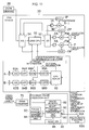
- FIG. 3 is a block diagram depicting the structure of the control system and the operation unit 30 of the lens device 20 described above.
- the focus lens F, the zoom lens Z, and the iris I configuring the optical system of the lens device 20 are depicted, and these are driven by motors FM, ZM, and IM.
- the lens device 20 includes a lens CPU (Central Processing Unit) 50 controlling the entirety in a centralized manner. From the lens CPU 50 to each of amplifiers FA, ZA, and IA of the motors FM, ZM, and IM, a drive signal is given via a D/A converter 52, each of the motors FM, ZM, and IM is driven at a speed corresponding to the voltage of the drive signal. Therefore, the focus lens F, the zoom lens Z, and the iris I can be controlled by the lens CPU 50 each at a desired operation speed.
- a lens CPU Central Processing Unit
- position signals indicating rotation positions of the motors FM, ZM, and IM are outputted from potentiometers FP, ZP, and IP, respectively, and are given to the lens CPU 50 via an A/D converter 54.
- the lens CPU 50 can read the positions of the focus lens F, the zoom lens Z, and the iris I. Therefore, the lens CPU 50 controls the operation speeds of the focus lens F, the zoom lens Z, and the iris I while reading the positions of the focus lens F, the zoom lens Z, and the iris I, thereby being able to perform control so that the focus lens F, the zoom lens Z, and the iris I are at desired positions.
- the control at the lens CPU 50 is performed according to an instruction signal given from the operation unit 30, which will be described in detail further below, or AF processing.
- the control is performed according to an instruction signal given from the zoom demand 28 via the A/D converter 54 based on an operation of an operation member manually operated by the operator.
- the control is performed according to an instruction signal (not illustrated) given from the camera body 18.
- control modes for focus control include an AF mode for focus control with AF described above and an MF mode for focus control with manual focus (MF).
- the AF mode includes an automatic tracking mode of automatically tracking a specific tracking target (for example, the human face or a subject instructed by the operator) and always bringing the tracking target into focus and a manual operation mode of manually setting the position and size of the AF frame by the operator. These modes can be selected as appropriate with a mode switch 86 provided on the operation unit 30.
- the operation unit 30 is formed by combining a conventional controller called a focus demand including an operation member (a focus ring) for focus manual operation and others and an AF-frame control device for AF-frame control, which will be described further below, and a block depicted as a focus demand 82 in the operation unit 30 of Figure 3 represents such a conventional focus demand.
- a focus demand including an operation member (a focus ring) for focus manual operation and others and an AF-frame control device for AF-frame control, which will be described further below
- a block depicted as a focus demand 82 in the operation unit 30 of Figure 3 represents such a conventional focus demand.
- Figure 4 is a perspective view of an outer appearance of the operation unit 30.
- the focus knob 42 for manually operating the focus of the lens device 20 is provided.
- This focus knob 42 is provided so as to be rotatable about the center axis, and has a shaft mounted so as to be orthogonal to the lateral surface of the body 36.
- a focus control signal is given from the focus demand 82 via the operation unit CPU 80 to the lens device 20, the focus control signal for making an instruction for movement of the focus (the focus lens F) with a focus position according to the rotation position being taken as a target position. With this, the focus lens of the lens device 20 moves to the target position instructed by the focus control signal.
- an operation panel 44 and the liquid-crystal panel 45 are provided on a front surface of the body 36 of the operation unit 30 .
- the operation panel 44 is provided with various operation members for performing operation regarding AF control details and MF control, such as a mode switch for switching between an AF mode and an MF mode and switching the type of AF mode (the automatic tracking mode and the manual operation mode) and an AF start switch for making an instruction for staring AF.
- a mode switch for switching between an AF mode and an MF mode and switching the type of AF mode (the automatic tracking mode and the manual operation mode) and an AF start switch for making an instruction for staring AF.
- On the liquid-crystal display panel 45 information about focus-control setting conditions and others are displayed.
- a processing circuit which detects a setting state of each of the various operation members and sends a control signal based on the detected setting state.
- a connector not illustrated is provided for electrical connection to the lens device 20.
- the operation unit 30 can transmit and receive various signals to and from the lens CPU 50 of the lens device 20.
- various control signals can be sent from the operation unit 30 to the lens device 20, and on the lens device 20 side, processes according to the control signals can be performed by the lens CPU 50.
- the body 36 of the operation unit 30 has incorporated therein the operation unit CPU 80, the image memory 88, and an image processing circuit 90 (refer to Figure 3 ) for specifying the AF frame (position, size, and shape (aspect ratio), with manual operation, which will be described further below, or the AF-frame automatic tracking process.
- a video input connector not illustrated for capturing a video signal into the operation unit CPU 80 is provided on a back surface of the body 36 of the operation unit 30, a video input connector not illustrated for capturing a video signal into the operation unit CPU 80 is provided.
- the operation unit 30 is connected via this video input connector to the camera body 18 with a communication cable. With this, the video signal outputted from the camera body 18 can be captured into the operation unit 30.
- a touch-panel-equipped liquid-crystal display (LCD) 100 can be mounted as operating means for performing operation regarding AF-frame control, and is mounted on the body 36 with a bracket 102 in the present embodiment.
- LCD liquid-crystal display
- This touch-panel-equipped LCD 100 allows settings of the automatic tracking mode, the manual operation mode, or the like regarding AF-frame setting to be inputted with a touch operation.
- the operation unit CPU 80 With the operation unit CPU 80, an image displayed on a screen thereof can be switched as appropriate according to the details of settings.
- a connector not illustrated is provided for electrical connection with this touch-panel-equipped LCD 100. Connected to the touch-panel-equipped LCD 100 via the connector and the communication cable, the operation unit 30 can transmit and receive various signals to and from the touch-panel-equipped LCD 100.
- the lens CPU 50 performs a process for focus control by MF (MF processing). That is, based on the rotation position of the focus knob 42 of the operation unit 30 (the focus demand 82), the position of the focus lens F is controlled so as to be a position instructed by the instruction signal given from the operation unit CPU 80 (a target position).
- MF processing a process for focus control by MF processing. That is, based on the rotation position of the focus knob 42 of the operation unit 30 (the focus demand 82), the position of the focus lens F is controlled so as to be a position instructed by the instruction signal given from the operation unit CPU 80 (a target position).
- the lens CPU 50 When a signal indicating that the AF mode has been selected is received from the operation unit CPU 80, the lens CPU 50 performs a process for focus control by AF (AF processing) for automatic focus adjustment, and performs a focus adjustment, automatically.
- AF AF processing
- AF can be performed with an optical path length difference scheme (a contrast scheme).
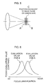
- AF of the optical path length difference scheme using the image pickup elements for AF, A and B, of the optical system for AF depicted in Figure 2 and Figure 3 is adopted.
- the image pickup elements for AF, A and B have different optical path lengths until the subject light enters the imaging face of each of the image pickup elements for AF, A and B, and the imaging faces of the image pickup elements for AF, A and B are placed at positions with an equal distance at front and back with respect to a position C, which serves as an optical path length matching with the imaging surfaces of the image pickup element 21 (21A, 21B, and 21C) of the camera body 18.
- contrasts (focus evaluation values) of images imaged by each of the image pickup elements for AF, A and B, are changed as depicted in Figure 6 .
- the focus evaluation values of the images imaged by the image pickup elements for AF, A and B are compared with each other, if these focus evaluation values match each other, it can be determined that the focus state with respect to the image pickup element for video 21 of the optical system for video is an in-focus state. That is, the contrast of the image imaged by the image pickup element for video 21 becomes maximum.
- the state is a frontal focus state if the focus evaluation value of the image pickup element for AF, A, is larger and the state is a back focus state if the focus evaluation value of the image pickup element for AF, B, is larger.
- the lens CPU 50 obtains the focus evaluation values of the images imaged by the image pickup elements for AF, A and B from a CPU for AF 60 to detect a focus state, moves the focus lens F based on the focus state, and sets the focus lens F at a position in the in-focus state.
- video signals (luminance signals) of video imaged by the image pickup elements for AF, A and B (video for AF) pass A/D converters 62A and 62B, high-pass filters (HPFs) 64A and 64B, gate circuits 66A and 66B, and adder circuits 68A and 68B, respectively. Then, focus evaluation values are found in units of video frames (in units of video screens) and read into the CPU for AF 60.
- the video signals of the video for AF imaged by the image pickup elements for AF, A and B are first converted by the A/D converters 62A and 62B to digital signals, and only high-frequency components are extracted by the HPFs 64A and 64B, respectively. Then, of the video signals of high-frequency components, video signals in an AF frame (in an AF area), which will be described further below, indicating a range (a AF target range) of a target subject to be brought into focus by AF are extracted by the gate circuits 66A and 66B. The values of the video signals in the AF frame are added together by the adder circuits 68A and 68B to find a focus evaluation value.
- the range of the AF frame from which the video signals are extracted by the gate circuits 66A and 66B is set by the CPU for AF 60.
- the CPU for AF 60 sets the range of the AF frame based on AF-frame information given from the operation unit 30 via the lens CPU 50.
- the AF frame is set as an outline of a rectangular area (an AF area) with respect to an imaging range image by the image pickup element for video 21, and at the time of the AF mode, a subject in the range of the AF frame can be brought into focus.
- an AF frame control device for AF-frame control is incorporated in the operation unit 30 as described above, and the operation unit CPU 80 for control the entirety in a centralized manner is included.
- the operation unit CPU 80 decides the range of the AF frame having a position, size, and shape (aspect ratio) being taken as elements, and transmits AF-frame information indicating the range of the AF frame to the lens CPU 50 via serial communication.
- the range of the AF frame is given from the lens CPU 50 to the CPU for AF 60 and the range of the video signal extracted at the gate circuits 66A and 66B is set as a range of the AF frame given from the operation unit CPU 80 of the operation unit 30.
- AF-frame control it is possible to select, as appropriate by the mode switch 86, the manual operation mode for setting the AF frame at a desired position in the imaging range with manual operation by the operator and the automatic tracking mode of automatically changing the AF frame range to the position (range) of a subject as a predetermine tracking target.
- the operation unit CPU 80 determines the range of the AF frame according to the manual operation of an operation member included in the AF-frame operating part 84 of Figure 3 .
- the operation panel 44 and the liquid-crystal display panel 45 provided to the body 36 of the operation unit 30 function as manual operating members.
- a joystick, a trackball, a knob, any of buttons, and others can be manual operation members for setting the position, size, and shape of the AF frame with manual operation by the operator.
- the touch-panel-equipped LCD 100 is mounted on the operation unit 30, that touch panel can be a manual operation member for setting the position, size, and others of the AF frame.
- the operation unit CPU 80 decides the position, size, and others of the AF frame based on the setting state of the manual operation members. Note that the AF-frame information indicating the position, size, and others of the AF frame currently set is given from the lens device 20 to the camera according to a request from the camera with the AF-frame display function, and is displayed in a superposed manner on the imaged vide on the view finder 22 installed in the camera body.
- the range of the subject of the tracking target is detected based on the video imaged by the image pickup element 21 of the camera body 18, and the operation unit CPU 80 decides that range as the range of the AF frame.
- the manual operation mode when an operation member for manually operating the position, size, and others of the AF frame is operated in the automatic tracking mode, that operation is prioritized, and the position, size, and others of the AF frame are set. With this, the subject at the time of start of automatic tracking can be specified.
- a video signal obtained by imaging by the image pickup element for video 21 of the camera body 18 and outputted from the camera body 18 is down-converted by a down converter 70 so as to have an appropriate resolution, and is then inputted to the operation unit 30. Then, images in units of frames are sequentially stored in an image memory 88 of the operation unit 30.
- the image processing circuit 90 performs a pattern matching process to detect a range matching a reference pattern registered in advance from among images stored in the image memory 88.
- a subject image in an initial range of the AF frame at the time of setting the automatic tracking mode is set as the reference pattern, and the subject is set as a tracking target. Note that in the case of automatic tracing of the face of a specific person, a human face area is detected in images stored in the image memory 88, and that face area can be taken as a tracking target.
- the operation unit CPU 80 takes a range where the reference pattern has been detected by the image processing circuit 90 as a subject range of the tracking target, and decides the range as a range of the AF frame. By sequentially repeating this process, the AF range is changed so as to tack the subject as the tracking target.
- Figure 7 is a flowchart depicting the AF-frame setting process at the lens device according to the first embodiment.
- the lens CPU 50 of the lens device 20 first perform initial settings including setting of a focus control mode, according to mode information inputted from the operation unit 30 and others (step S10). Subsequently, the lens CPU 50 performs processes other than AF-frame display (for example, focus control based on the AF frame currently set, zoom control based on a zoom control signal from the zoom demand 28, or control of the iris I based on an instruction signal given from the camera body 18) (step S12).
- processes other than AF-frame display for example, focus control based on the AF frame currently set, zoom control based on a zoom control signal from the zoom demand 28, or control of the iris I based on an instruction signal given from the camera body 18
- step S 14 it is determined whether a request for AF-frame information from the camera body 18 where the lens device 20 is mounted is present (step S 14).
- a request for AF-frame information is made to the lens device 20 for AF-frame information required to superpose the AF frame on the video in the view finder on a camera side.
- the camera body 18 does not have the AF-frame display function, a request is not made to the lens device 20 for AF-frame information.
- the camera body 18 and the lens device 20 transmit and receive various information through serial communications via a serial communication interface (SCI) provided to each.
- SCI serial communication interface
- the lens CPU 50 determines that the device is mounted on a camera with the AF-frame display function, and transmits information about the position and size of the current AF frame (AF-frame information) via the SCI to the camera body 18 (step S16). With this, the camera body 18 can superpose and display the AF frame indicating the AF area where AF is currently being performed on video displayed on the view finder 22.
- the lens CPU 50 requests the position, size, and mode of the AF frame from the operation unit 30 (step S 18), and receives information about the position, size, and mode of the AF frame set on an operation unit 30 side (step S20). Then, this is reflected to AF, preparing for a request for obtaining AF-frame information from the camera next time.
- the lens CPU 50 determines that the lens device is mounted on a camera without the AF-frame display function, and causes the procedure to make a transition to step 22.
- step S22 it is determined whether an AF-frame automatic tracking mode has been set by the operation unit 30. Then, when it is determined that the AF-frame control mode is an automatic tracking mode ("in the case of YES"), the procedure is caused to make a transition to step S18, obtaining AF-frame information from the operation unit 30 (steps S18 and S20). That is, the AF frame can be updated in the automatic tracking mode.
- the AF-frame control mode is an automatic tracking mode ("in the case of YES"
- the AF-frame information is not transmitted to the camera body, and no AF frame is displayed on the view finder of the camera.
- the subject is automatically tracked with the AF frame, thereby posing no problem in AF-frame operation even if the AF frame is not displayed.
- step S24 the lens CPU 50 sets the position and size of the AF frame at predetermined values of the position and size set in advance (fixes the AF frame). With this, the lens device 20 performs AF according to the fixed AF frame.
- the AF frame is not displayed on the view finder of the camera, but the AF frame is fixed at a predetermined position and size. Therefore, even if the position or size of the AF frame is changed in the manual operation mode, that change is not reflected in AF. With this, it is possible to avoid an inconvenience in which the lens device 20 performs AF according to the position and size of the AF frame not intended by the operator.
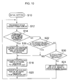
- Figure 10 is a flowchart depicting the AF-frame setting process at the lens device according to the second embodiment. Note that portions common to those in the flowchart of the first embodiment depicted in Figure 7 are provided with the same step numbers and are not described in detail.
- the second embodiment is different from the first embodiment in that a process of step S30 is added.
- step S22 when the AF-frame control mode is not an automatic tracking mode ("in the case of NO") in step S22, the procedure is caused to make a transition to step S30.
- step S30 it is determined whether the touch-panel-equipped LCD 100 is mounted on the operation unit 30.
- the operation unit CPU 80 of the operation unit 30, the image processing circuit 90, and the touch-panel-equipped LCD 100 are electrically connected via a communication cable 104, and transmit and receive various signals including a video signal to and from each other.
- position information indicating the touched position (coordinates) is given to the operation unit CPU 80.
- the position of the touch operation and the type of the operation (such as a tap operation or a double-tap operation) performed on the screen of the touch-panel-equipped LCD 100 is detected by the operation unit CPU 80.
- an AF-frame control mode according to the operation can be selected, and the position, size, shape, and others of the AF frame in the manual operation mode can be set.
- the touch-panel-equipped LCD 100 can display the AF frame together with video being imaged by the camera body.
- the touch-panel-equipped LCD 100 may receive the video signal and the AF-frame information from the operation unit 30, and the touch-panel-equipped LCD 100 may perform an AF-frame superposing process.
- the operation unit CPU 80 determines whether the touch-panel-equipped LCD 100 is mounted, and the operation unit CPU 80 sends the determination result to the lens CPU 50.
- the determination as to whether the touch-panel-equipped LCD 100 is mounted on the operation unit 30 can be made by using a detection output of a microswitch which detects a mechanical connection between the operation unit 30 and the touch-panel-equipped LCD 100 with the bracket 102, as depicted in Figure 4 .
- the determination can be made by using a detection output of detecting means which detects the presence or absence of the connection of the communication cable 104 ( Figure 11 ) electrically connecting both.
- the lens CPU 50 When receiving, from the operation unit CPU 80, information indicating that the touch-panel-equipped LCD 100 is mounted ("in the case of YES" at step S30 of Figure 10 ), the lens CPU 50 causes the procedure to make a transition to step S18.
- the lens CPU 50 obtains the AF-frame information from the operation unit 30 (steps S18 and S20), allowing the AF frame to be changed.
- the position and size of the AF frame can be manually changed, and the lens device 20 can perform AF according to the AF frame after change.
- the AF frame is displayed on the touch-panel-equipped LCD 100.
- the operator can check the position and size of the AF frame on the touch-panel-equipped LCD, and there is no problem even if the camera does not have the AF-frame display function.
- the lens CPU 50 when receiving, from the operation unit CPU 80, information indicating that the touch-panel-equipped LCD 100 is not mounted ("in the case of NO" at step S30 of Figure 10 ), the lens CPU 50 causes the procedure to make a transition to step S24.
- the AF frame is fixed at the position and size set in advance, and an inconvenience can be avoided in which AF is performed according to the position and size of the AF frame not intended by the operator.
- the lens CPU 50 fixes/cancels the fixing of the AF frame based on the mode of transmission from the operation unit 30 to the lens CPU 50 of the lens device 20, the information indicating the presence or absence of mounting of the touch-panel-equipped LCD 100, and others.
- the present invention is not restricted to this.
- the operation unit CPU 80 on the operation unit side may fix/cancel the fixing of the AF frame.
- the operation unit CPU 80 is required to obtain information about the camera (information indicating whether the camera has the AF-frame display function) from the lens CPU 50.
- the lens device 20 of the embodiments is a lens device in a strict sense not including the zoom demand 28, the operation unit 30, and the touch-panel-equipped LCD 100
- these zoom demand 28, operation unit 30, and touch-panel-equipped LCD 100 are devices attached to the lens device 20, being electrically connected directly or indirectly to the lens device 20 to operate the lens device 20, and a lens device in a broad sense includes these zoom demand 28, operation unit 30, and touch-panel-equipped LCD 100.
- the AF scheme is not restricted to the scheme of the present embodiments, various schemes can be applied, and the touch-panel-equipped LCD 100 may not include a touch panel.
Landscapes
- Physics & Mathematics (AREA)
- Engineering & Computer Science (AREA)
- Multimedia (AREA)
- Signal Processing (AREA)
- General Physics & Mathematics (AREA)
- Optics & Photonics (AREA)
- Computer Vision & Pattern Recognition (AREA)
- Automatic Focus Adjustment (AREA)
- Studio Devices (AREA)
- Focusing (AREA)
Applications Claiming Priority (2)
| Application Number | Priority Date | Filing Date | Title |
|---|---|---|---|
| JP2011023932 | 2011-02-07 | ||
| PCT/JP2012/052075 WO2012108294A1 (ja) | 2011-02-07 | 2012-01-31 | レンズ装置 |
Publications (2)
| Publication Number | Publication Date |
|---|---|
| EP2674801A1 true EP2674801A1 (de) | 2013-12-18 |
| EP2674801A4 EP2674801A4 (de) | 2017-09-13 |
Family
ID=46638510
Family Applications (1)
| Application Number | Title | Priority Date | Filing Date |
|---|---|---|---|
| EP12744560.9A Withdrawn EP2674801A4 (de) | 2011-02-07 | 2012-01-31 | Linsenvorrichtung |
Country Status (4)
| Country | Link |
|---|---|
| US (1) | US8964099B2 (de) |
| EP (1) | EP2674801A4 (de) |
| JP (1) | JP5705883B2 (de) |
| WO (1) | WO2012108294A1 (de) |
Cited By (1)
| Publication number | Priority date | Publication date | Assignee | Title |
|---|---|---|---|---|
| CN112087579A (zh) * | 2020-09-17 | 2020-12-15 | 维沃移动通信有限公司 | 视频拍摄方法、装置和电子设备 |
Families Citing this family (9)
| Publication number | Priority date | Publication date | Assignee | Title |
|---|---|---|---|---|
| KR20140102443A (ko) * | 2013-02-14 | 2014-08-22 | 삼성전자주식회사 | 카메라를 이용한 물체 추적 방법 및 이를 위한 카메라 시스템 |
| JP6516443B2 (ja) * | 2014-11-10 | 2019-05-22 | オリンパス株式会社 | カメラシステム |
| US11240421B2 (en) * | 2015-04-10 | 2022-02-01 | Qualcomm Incorporated | Methods and apparatus for defocus reduction using laser autofocus |
| JP6657247B2 (ja) * | 2015-10-27 | 2020-03-04 | オリンパス株式会社 | 撮像装置、内視鏡装置及び撮像装置の作動方法 |
| DE102015121017A1 (de) | 2015-12-03 | 2017-06-08 | Karl Storz Gmbh & Co. Kg | Beobachtungsvorrichtung, insbesondere medizinische Beobachtungsvorrichtung, mit einer Bedieneinheit sowie Verwendung eines Eingabemoduls |
| JP6719899B2 (ja) * | 2015-12-16 | 2020-07-08 | キヤノン株式会社 | 撮像装置、その制御方法、および制御プログラム |
| CN108200319B (zh) * | 2018-01-09 | 2020-09-18 | 佛山华国光学器材有限公司 | 一种大变倍一体化摄像机及其自动控制方法 |
| JP7049179B2 (ja) * | 2018-05-14 | 2022-04-06 | キヤノン株式会社 | 撮像制御装置およびその制御方法、プログラム並びに記憶媒体 |
| CN113556466B (zh) * | 2021-06-29 | 2023-01-13 | 荣耀终端有限公司 | 一种对焦方法和电子设备 |
Family Cites Families (14)
| Publication number | Priority date | Publication date | Assignee | Title |
|---|---|---|---|---|
| US6683652B1 (en) * | 1995-08-29 | 2004-01-27 | Canon Kabushiki Kaisha | Interchangeable lens video camera system having improved focusing |
| JPH10173980A (ja) | 1996-12-11 | 1998-06-26 | Sony Corp | オートフォーカス装置 |
| JP4408001B2 (ja) * | 2000-12-21 | 2010-02-03 | キヤノン株式会社 | 撮像装置および撮像システム |
| US20040036792A1 (en) * | 2002-08-23 | 2004-02-26 | Chikatsu Moriya | Camera system and focus information display apparatus |
| JP4525089B2 (ja) * | 2004-01-27 | 2010-08-18 | フジノン株式会社 | オートフォーカスシステム |
| EP1601189A2 (de) * | 2004-05-26 | 2005-11-30 | Fujinon Corporation | Autofokussystem |
| JP4196884B2 (ja) | 2004-06-01 | 2008-12-17 | フジノン株式会社 | オートフォーカスシステム |
| JP2006113265A (ja) | 2004-10-14 | 2006-04-27 | Fujinon Corp | オートフォーカスシステム |
| JP2006195342A (ja) | 2005-01-17 | 2006-07-27 | Fujinon Corp | Afエリア操作装置 |
| EP1659783A3 (de) | 2004-11-19 | 2006-05-31 | Fujinon Corporation | Vorrichtung zur AF Gebietanzeige und Vorrichtung zur AF Gebietsteuerung |
| JP4711073B2 (ja) * | 2006-03-14 | 2011-06-29 | 富士フイルム株式会社 | オートフォーカスシステム |
| JP2010049148A (ja) * | 2008-08-25 | 2010-03-04 | Nikon Corp | 画像認識装置及び撮像装置 |
| JP2010097167A (ja) * | 2008-09-22 | 2010-04-30 | Fujinon Corp | オートフォーカス装置 |
| JP2010124120A (ja) * | 2008-11-18 | 2010-06-03 | Fujinon Corp | オートフォーカスシステム |
-
2012
- 2012-01-31 EP EP12744560.9A patent/EP2674801A4/de not_active Withdrawn
- 2012-01-31 WO PCT/JP2012/052075 patent/WO2012108294A1/ja active Application Filing
- 2012-01-31 JP JP2012556831A patent/JP5705883B2/ja not_active Expired - Fee Related
-
2013
- 2013-08-02 US US13/957,728 patent/US8964099B2/en not_active Expired - Fee Related
Non-Patent Citations (1)
| Title |
|---|
| See references of WO2012108294A1 * |
Cited By (2)
| Publication number | Priority date | Publication date | Assignee | Title |
|---|---|---|---|---|
| CN112087579A (zh) * | 2020-09-17 | 2020-12-15 | 维沃移动通信有限公司 | 视频拍摄方法、装置和电子设备 |
| CN112087579B (zh) * | 2020-09-17 | 2022-08-12 | 维沃移动通信有限公司 | 视频拍摄方法、装置和电子设备 |
Also Published As
| Publication number | Publication date |
|---|---|
| US8964099B2 (en) | 2015-02-24 |
| EP2674801A4 (de) | 2017-09-13 |
| US20130314579A1 (en) | 2013-11-28 |
| JP5705883B2 (ja) | 2015-04-22 |
| JPWO2012108294A1 (ja) | 2014-07-03 |
| WO2012108294A1 (ja) | 2012-08-16 |
Similar Documents
| Publication | Publication Date | Title |
|---|---|---|
| US8964099B2 (en) | Lens device capable of utilizing an AF-frame automatic tracking function | |
| EP2178292B1 (de) | Autofokussystem mit automatischer rahmenortungsfunktion | |
| EP1603328B1 (de) | Autofokussystem | |
| EP2293542A2 (de) | System zur automatischen Autofokus-Rahmen-Verfolgung | |
| JP2011133821A (ja) | オートフォーカスシステム | |
| JP2010124120A (ja) | オートフォーカスシステム | |
| JPWO2012099175A1 (ja) | オートフォーカスシステム | |
| US20100123790A1 (en) | Autofocus system | |
| EP2237552B1 (de) | Autofokussystem | |
| EP2178291B1 (de) | Autofokussystem mit automatischer Rahmenortungsfunktion | |
| JP5081133B2 (ja) | オートフォーカスシステム | |
| JP4711073B2 (ja) | オートフォーカスシステム | |
| JP5328616B2 (ja) | Af枠自動追尾システム | |
| JP5276538B2 (ja) | Af枠自動追尾システム | |
| EP2187625B1 (de) | Autofokussystem | |
| JP2010230871A (ja) | オートフォーカスシステム | |
| WO2012099174A1 (ja) | オートフォーカスシステム | |
| JP2011022499A (ja) | オートフォーカスシステム | |
| JP2010164637A (ja) | Af枠自動追尾システム | |
| JP4834009B2 (ja) | テレビカメラシステム | |
| JP2010224499A (ja) | オートフォーカスシステム | |
| JP2006084999A (ja) | Afエリア操作システム | |
| JP2010122366A (ja) | オートフォーカスシステム | |
| JP2006145872A (ja) | Afエリア表示装置 | |
| JP2010122365A (ja) | Af枠自動追尾システム |
Legal Events
| Date | Code | Title | Description |
|---|---|---|---|
| PUAI | Public reference made under article 153(3) epc to a published international application that has entered the european phase |
Free format text: ORIGINAL CODE: 0009012 |
|
| 17P | Request for examination filed |
Effective date: 20130806 |
|
| AK | Designated contracting states |
Kind code of ref document: A1 Designated state(s): AL AT BE BG CH CY CZ DE DK EE ES FI FR GB GR HR HU IE IS IT LI LT LU LV MC MK MT NL NO PL PT RO RS SE SI SK SM TR |
|
| DAX | Request for extension of the european patent (deleted) | ||
| RA4 | Supplementary search report drawn up and despatched (corrected) |
Effective date: 20170810 |
|
| RIC1 | Information provided on ipc code assigned before grant |
Ipc: G02B 7/28 20060101AFI20170804BHEP Ipc: H04N 5/232 20060101ALI20170804BHEP Ipc: H04N 5/225 20060101ALI20170804BHEP Ipc: G03B 13/36 20060101ALI20170804BHEP Ipc: G02B 7/36 20060101ALI20170804BHEP |
|
| STAA | Information on the status of an ep patent application or granted ep patent |
Free format text: STATUS: THE APPLICATION HAS BEEN WITHDRAWN |
|
| 17Q | First examination report despatched |
Effective date: 20181220 |
|
| 18W | Application withdrawn |
Effective date: 20190111 |