EP2178292B1 - Autofokussystem mit automatischer rahmenortungsfunktion - Google Patents
Autofokussystem mit automatischer rahmenortungsfunktion Download PDFInfo
- Publication number
- EP2178292B1 EP2178292B1 EP09011284.8A EP09011284A EP2178292B1 EP 2178292 B1 EP2178292 B1 EP 2178292B1 EP 09011284 A EP09011284 A EP 09011284A EP 2178292 B1 EP2178292 B1 EP 2178292B1
- Authority
- EP
- European Patent Office
- Prior art keywords
- frame
- image
- face
- face image
- cpu
- Prior art date
- Legal status (The legal status is an assumption and is not a legal conclusion. Google has not performed a legal analysis and makes no representation as to the accuracy of the status listed.)
- Active
Links
Images


Classifications
-
- H—ELECTRICITY
- H04—ELECTRIC COMMUNICATION TECHNIQUE
- H04N—PICTORIAL COMMUNICATION, e.g. TELEVISION
- H04N23/00—Cameras or camera modules comprising electronic image sensors; Control thereof
- H04N23/60—Control of cameras or camera modules
- H04N23/67—Focus control based on electronic image sensor signals
- H04N23/675—Focus control based on electronic image sensor signals comprising setting of focusing regions
-
- H—ELECTRICITY
- H04—ELECTRIC COMMUNICATION TECHNIQUE
- H04N—PICTORIAL COMMUNICATION, e.g. TELEVISION
- H04N23/00—Cameras or camera modules comprising electronic image sensors; Control thereof
- H04N23/60—Control of cameras or camera modules
- H04N23/61—Control of cameras or camera modules based on recognised objects
- H04N23/611—Control of cameras or camera modules based on recognised objects where the recognised objects include parts of the human body
-
- H—ELECTRICITY
- H04—ELECTRIC COMMUNICATION TECHNIQUE
- H04N—PICTORIAL COMMUNICATION, e.g. TELEVISION
- H04N23/00—Cameras or camera modules comprising electronic image sensors; Control thereof
- H04N23/60—Control of cameras or camera modules
- H04N23/63—Control of cameras or camera modules by using electronic viewfinders
- H04N23/631—Graphical user interfaces [GUI] specially adapted for controlling image capture or setting capture parameters
-
- H—ELECTRICITY
- H04—ELECTRIC COMMUNICATION TECHNIQUE
- H04N—PICTORIAL COMMUNICATION, e.g. TELEVISION
- H04N23/00—Cameras or camera modules comprising electronic image sensors; Control thereof
- H04N23/60—Control of cameras or camera modules
- H04N23/63—Control of cameras or camera modules by using electronic viewfinders
- H04N23/633—Control of cameras or camera modules by using electronic viewfinders for displaying additional information relating to control or operation of the camera
- H04N23/635—Region indicators; Field of view indicators
-
- H—ELECTRICITY
- H04—ELECTRIC COMMUNICATION TECHNIQUE
- H04N—PICTORIAL COMMUNICATION, e.g. TELEVISION
- H04N23/00—Cameras or camera modules comprising electronic image sensors; Control thereof
- H04N23/60—Control of cameras or camera modules
- H04N23/64—Computer-aided capture of images, e.g. transfer from script file into camera, check of taken image quality, advice or proposal for image composition or decision on when to take image
-
- H—ELECTRICITY
- H04—ELECTRIC COMMUNICATION TECHNIQUE
- H04N—PICTORIAL COMMUNICATION, e.g. TELEVISION
- H04N23/00—Cameras or camera modules comprising electronic image sensors; Control thereof
- H04N23/60—Control of cameras or camera modules
- H04N23/67—Focus control based on electronic image sensor signals
- H04N23/673—Focus control based on electronic image sensor signals based on contrast or high frequency components of image signals, e.g. hill climbing method
Definitions
- the present invention relates to an auto focus system having an AF frame auto-tracking function, and more particularly, to an auto focus system having an AF frame auto-tracking function that allows an AF area (AF frame), which is the target range of an object brought into focus by auto focus (AF), to follow a predetermined object moved on an imaging screen.
- AF frame AF area
- AF frame AF area
- AF auto focus
- This type of camera system generally uses contrast-type AF.
- the camera system detects the level of the contrast of the captured image, and controls the focus of an imaging optical system such that the contrast becomes the maximum (the largest).
- the target range of an object that is brought into focus by AF is not the entire screen of the captured image, but is limited to a portion of the screen, which is called an AF area. Focus control is performed such that the contrast of the captured image (object image) in the AF area becomes the maximum, thereby focusing on the object in the AF area.
- AF frame a frame indicating the outline of the AF area.
- JP-A-2006-258944 (corresponding to US 2006/210260 A ) discloses an auto focus system having an AF frame auto-tracking function that allows the AF frame to automatically follow a desired object moved on the screen of the captured image such that the object is continuously in focus.
- the auto-tracking of the AF frame is performed by detecting the image of an object to be tracked from the captured image and moving the AF frame to the detected position.
- JP-A-2006-258944 discloses a method of storing the image of the object to be tracked as a reference pattern and detecting an image matched with the reference pattern from the captured image using a pattern matching process.
- the user wants to use the AF frame auto-tracking function to track, for example, a person's face.
- the size of the AF frame is excessively larger than that of the face (face image) in the captured image
- a large portion of the background image is included in the AF frame.
- the imaging device focuses on the background in the contrast-type AF.
- the image of a reference pattern is set to an initial image in the AF frame or an image in a range corresponding to the AF frame in the pattern matching process. Therefore, when the background image of the face image varies, it is difficult to detect an image matched with the image of the reference pattern in the pattern matching process. Therefore, it is difficult to move the AF frame to track the face image.
- the AF frame auto-tracking function starts to set the AF frame to an appropriate size corresponding to the size of the face image to be tracked
- the size of the face image in the AF frame is changed when a zoom operation of an imaging lens (imaging optical system) is performed or when the distance between a camera and an object varies. Therefore, for example, when the zoom operation is performed to a wide side, the size of the face image in the captured image is reduced, which causes the above-mentioned problems.
- the zoom operation is performed to a telephoto side, a portion of the face image is within the range of the AF frame, and high frequency components are reduced. As a result, it is difficult to perform focusing on the object by AF.
- the pattern matching process it is difficult to detect an image matched with the image of the reference pattern. Therefore, it is difficult to move the AF frame to track the face image.
- EP 1 968 310 A2 discloses a focusing device capable of setting a focusing area according to the result of detecting a target subject.
- EP 1 909 229 A2 and EP 1 677 521 A1 disclose an auto focus system capable of focusing while following a desired target subject by automatically moving the position of an AF frame including the desired target subject in a photographing range of a camera.
- a reference pattern frame of the desired target subject and a pattern matching process are used to update the position of the AF frame.
- the invention has been made in order to solve the above-mentioned problems, and an object of the invention is to provide an auto focus system according to claim 1.
- the range of the AF frame is automatically changed so as to correspond to the position and size of the face image. Therefore, the user does not need to accurately set the AF frame according to the size of the face image in the captured image. Even when the size of the face image is changed by, for example, a zoom operation, the size of the AF frame is automatically changed to an appropriate size.
- the AF frame is automatically set in an appropriate range suitable for the position and size of the face image. Therefore, it is possible to appropriately track the face image and appropriately perform focusing on the face by AF.
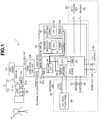
- Fig. 1 is a block diagram illustrating the overall structure of a video camera system according to the invention.
- the video camera system is an imaging system that is used to capture images with, for example, a broadcasting television camera.
- a video camera system 1 includes a television camera 10 and an image processing unit 18.
- the television camera 10 includes a camera body 12, which is an HD camera corresponding to a high-definition television [HD TV] system, and a lens device 14 including an imaging lens (optical system) mounted to a lens mount of the camera body 12.
- a camera body 12 which is an HD camera corresponding to a high-definition television [HD TV] system
- the camera body 12 is provided with an imaging device (for example, a CCD) and a predetermined signal processing circuit.
- the image formed by the imaging lens of the lens device 14 is converted into electric signals by the imaging device, and the signal processing circuit performs predetermined signal processing on the electric signals to generate HDTV video signals (HDTV signals).
- the generated HDTV video signals are output from a video signal output terminal of the camera body 12 to the outside.
- the camera body 12 also includes a viewfinder 13, and an image that is being currently captured by the television camera 10 is displayed on the viewfinder 13.
- various information items are displayed on the viewfinder 13. For example, an AF frame, which is a focus target range during auto focus (which will be described below), is displayed so as to overlap a captured image.
- the lens device 14 includes an imaging lens (zoom lens) 24 mounted to the lens mount of the camera body 12.
- the imaging lens 24 focuses an object 16 on the imaging surface of the imaging device of the camera body 12.
- the imaging lens 24 includes, as components, movable portions for adjusting imaging conditions, such as a focus lens group, a zoom lens group, and an aperture diaphragm. These movable portions are electrically driven by a motor (servo mechanism). For example, the focus lens group is moved in the optical axis direction to adjust the focus (object distance), and the zoom lens group is moved in the optical axis direction to adjust the focal length (zoom ratio).
- At least the focus lens group may be electrically driven, and the other movable portions may be manually driven.
- the operation of the movable portions is controlled on the basis of control signals output from an operating unit (not shown) (for example, an operating unit of a controller connected to the lens device 14) operated by the operator, but a detailed description thereof is omitted.
- the lens device 14 further includes an AF unit 26 and a lens CPU (not shown).
- the lens CPU controls the overall operation of the lens device 14.
- the AF unit 26 is a processing unit that acquires information required to perform AF control (auto focus), and includes an AF processing unit (not shown) and an imaging circuit for AF (not shown).
- the imaging circuit for AF is provided in the lens device 14 in order to acquire video signals for AF, and includes an imaging device (which is referred to as an imaging device for AF), such as a CCD, and a processing circuit that outputs a signal from the imaging device for AF as a video signal of a predetermined format.
- the video signal output from the imaging circuit for AF is a brightness signal.
- Object light branched from the object light incident on the imaging device of the camera body 12 by, for example, a half mirror provided on the optical path of the imaging lens 24 is focused on the imaging surface of the imaging device for AF.
- the imaging range and the object distance (the distance to an object in focus) in the imaging area of the imaging device for AF are equal to the imaging range and the object distance in the imaging area of the imaging device of the camera body 12.
- the object image captured by the imaging device for AF is identical to that captured by the imaging device of the camera body 12.
- the two imaging ranges do not need to be completely equal to each other.
- the imaging range of the imaging device for AF may include the imaging range of the imaging device of the camera body 12.
- the AF processing unit acquires a video signal from the imaging circuit for AF, and calculates a focus evaluation value indicating the level of the contrast of the image of the object on the basis of the video signal.
- high-frequency component signals are extracted from the video signals obtained by the imaging device for AF by a high pass filter, and among the high-frequency component signals, signals that correspond to one screen (one frame) and are in a range corresponding to an AF area to be subjected to AF processing are integrated.
- the integrated value corresponding to each screen indicates the level of the contrast of the image of the object, and is given as a focus evaluation value to the lens CPU.
- the lens CPU acquires the information of the AF frame (AF frame information) indicating the range (outline) of the AF area from the image processing unit 18, which will be described below, and designates, as the AF area, the range of the AF frame designated by the AF frame information to the AF processing unit. Then, the lens CPU acquires the focus evaluation value calculated by the image (video signal) in the AF area from the AF processing unit.
- AF frame information the information of the AF frame (AF frame information) indicating the range (outline) of the AF area from the image processing unit 18, which will be described below
- the lens CPU acquires the focus evaluation value from the AF processing unit, and controls the focus lens group such that the acquired focus evaluation value is the maximum (the largest), that is, the contrast of the image of the object in the AF frame is the maximum.
- a hill-climbing method has been known as the method of controlling the focus lens group on the basis of the focus evaluation value. In the hill-climbing method, the focus lens group is moved in a direction in which the focus evaluation value increases, and when a point where the focus evaluation value starts to decrease is detected, the focus lens group is set to the point. In this way, the imaging device is automatically focused on the object in the AF frame.
- the AF processing unit acquires the video signal from the imaging device for AF mounted to the lens device in order to calculate the focus evaluation value.
- the AF processing unit may acquire the video signal of the image captured by the imaging device of the camera body 12 from the camera body 12.
- any AF unit may be used for auto focusing on the object in the AF frame.
- the camera body 12 and the lens device 14, and the lens device 14 and the image processing unit 18, which will be described below, are connected to each other by serial communication connectors provided therein directly or through cables.
- the camera body 12 and the lens device 14 are connected to each other by serial communication interfaces (SCI) 12a and 14a respectively provided therein such that various information items can be transmitted therebetween by serial communication.
- SCI serial communication interfaces
- the lens device 14 and the image processing unit 18 are connected to each other by serial communication interfaces 14a and 30a respectively provided therein such that various information items can be transmitted therebetween by serial communication.
- a video output connector of the camera body 12 and a video input connector of the image processing unit 18 are connected to each other by a cable with a down converter 28 interposed therebetween.
- the HDTV signal output from the video output connector of the camera body 12 is converted (down-converted) into a video signal (SDTV signal) of a standard television [NTSC (national television system committee)] format by the down converter 28, and the converted video signal is input to the image processing unit 18.
- SDTV signal standard television [NTSC (national television system committee)] format
- the image processing unit 18 designates the range (the position, size, and shape (aspect ratio)) of the AF frame when the AF unit 26 of the lens device 14 performs AF control.
- the image processing unit 18 transmits AF frame information designating the range of the AF frame in the image (imaging screen) captured by the television camera 10 to the lens device 14 using the serial communication.
- the AF unit 26 sets the range of the AF frame on the basis of the AF frame information transmitted from the image processing unit 18, and performs AF processing as described above.
- the image processing unit 18 mainly includes a main board 30, a pattern matching board 32, and a face detecting board 34.
- the main board 30, the pattern matching board 32, and the face detecting board 34 respectively include CPUs 38, 50, and 52 such that the boards individually perform operating processes.
- the CPUs 38, 50, and 52 are connected to each other by a bus or a control line such that they perform data communication therebetween or the operating processes are synchronized with each other.
- the main board 30 controls the overall operation of the image processing unit 18.
- the main board 30 includes an SCI 30a, a decoder (A/D converter) 36, a superimposer 42, and a RAM 40 in addition to the CPU 38 that performs an operating process.
- the SCI 30a is an interface circuit for serial communication with the SCI 14a of the lens device 14, and transmits, for example, the AF frame information to the lens device 14.
- the decoder 36 is a circuit for converting the video signal (SDTV signal) of the image captured by the television camera 10, which is input from the down converter 28 to the image processing unit 18, into digital data that can be processed by the image processing unit 18, and performs an A/D converting process of converting an analog SDTV signal into a digital video signal.
- SDTV signal video signal
- the decoder 36 is a circuit for converting the video signal (SDTV signal) of the image captured by the television camera 10, which is input from the down converter 28 to the image processing unit 18, into digital data that can be processed by the image processing unit 18, and performs an A/D converting process of converting an analog SDTV signal into a digital video signal.
- the RAM 40 is a memory that temporarily stores data used in the operating process of the CPU 38.
- the pattern matching board 32 or the face detecting board 34 are arithmetic boards that individually perform a pattern matching process and a face detecting process, and include, for example, VRAMs 54 and 56 that temporarily store image data, in addition to the CPUs 50 and 52 that perform the operating processes.
- the operating unit 20 is provided integrally with the image processing unit 18, or some or all of the operating members of the operating unit 20 are provided separately from the image processing unit 18 and connected to the image processing unit 18 by, for example, cables.
- the operating unit 20 includes a position operating member 60 (for example, a joystick or a trackball) that is manually operated by the user to move the position of the AF frame in the horizontal and vertical directions, a size operating member 62 (for example, a knob) that is manually operated by the user to change the size of the AF frame, a shape operating member 64 (for example, a knob) that is manually operated by the user to change the shape of the AF frame, a tracking start switch 68 that instructs the start of auto-tracking, and a tracking stop switch 70 that instructs the stopping of the auto-tracking.
- the CPU 38 of the main board 30 of the image processing unit 18 reads the set states of the operating members 60, 62, 64, 68, and 70.
- the user touches an LCD 66 with a touch panel to set the mode related to AF frame auto-tracking.
- the image displayed on the LCD 66 with a touch panel is appropriately changed by the CPU 38 of the image processing unit 18 depending on the set conditions.
- the image displayed on the LCD 66 with a touch panel is transmitted from the superimposer 42 of the main board 30.
- the superimposer 42 composes the video signal of the image captured by the television camera 10, which is transmitted from the decoder 36, and the image signal generated by the CPU 38.
- the user can touch the screen to perform the same operations as that performed by the operating members 60, 62, 64, 68, and 70.
- a process of setting the AF frame (AF frame setting process) performed by the lens device 14 under the control of the image processing unit 18 having the above-mentioned structure according to this embodiment will be described with reference to some embodiments.
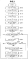
- a first embodiment of the AF frame setting process will be described with reference to the flowchart shown in Fig. 2 .
- the range of the AF frame is automatically changed so as to be matched with the face to be tracked.
- the range of the AF frame is determined by the position, size, and shape (aspect ratio) of the AF frame, and a change in the range of the AF frame means a change in at least one of the position, size, and shape of the AF frame.
- the user operates the operating unit 20 to designate the AF frame at the beginning such that an object to be tracked as an AF target is included in the AF frame.
- the user designates an AF frame 100 so as to include a face image 102 of a predetermined person, which is an object to be tracked, and sets the AF frame such that only the face of one person is included in the AF frame.
- the AF frame is designated so as to include the faces of a plurality of persons. However, when a portion of the face is included in the AF frame, the face is regarded to be included in the AF frame.
- the CPU 38 of the main board 30 sets the AF frame to be transmitted to the lens device 14 on the basis of the operation of the user (Step S10). Then, the CPU 38 starts an AF frame auto-tracking process (Step S12). For example, the auto-tracking process starts when a tracking start switch 68 of the operating unit 20 is turned on.
- the CPU 38 inputs one frame of image data of the captured image in the digital image signals of the captured image output from the decoder 36 to the face detecting board 34 (Step S14) .
- the CPU 52 of the face detecting board 34 performs a face detecting process of detecting the image of a face (face image) from the captured image and detects the face image included in the AF frame (Step S16).
- the position, size, and shape of the AF frame that includes the entire face but does not include any other objects are calculated on the basis of the position, size, and shape of the face image included in the AF frame, and the AF frame to be transmitted to the lens device 14 is updated to the calculated AF frame (Step S18).
- the AF frame is updated to the AF frame 100 having a size suitable for the size of the face image 102 by the updating process in Step S18, as shown in Fig. 3B .
- the image data in the AF frame is set as image data of a reference pattern in a pattern matching process, which will be described below (Step S20).
- the image data of the reference pattern does not need to be completely equal to the size of the AF frame, but the image data may be larger or smaller than the AF frame.
- the following process from Steps S22 to S36 is repeatedly performed to track the face image in the AF frame and update the size of the AF frame according to the size of the tracked face image.
- the size of the AF frame includes the shape of the AF frame.
- the aspect ratio of the AF frame may be updated to correspond to the face image, or the aspect ratio of the AF frame may be constant.
- Step S22 the CPU 38 inputs one frame of image data of the captured image from the decoder 36 to the pattern matching board 32 and the face detecting board 34.
- the CPU 50 of the pattern matching board 32 performs a pattern matching process of detecting the image matched with the reference pattern from the captured image and the position thereof (Step S24).
- the CPU 38 determines whether the image matched with the reference pattern, that is, a face image to be tracked is moved into the captured image on the basis of the result of the pattern matching process in Step S24 (Step S26).
- the determination of the movement of the face image includes the enlargement and reduction of the face image by zooming or the movement of an object in a forward or backward direction.
- Step S26 If the determination result of Step S26 is 'NO', the process returns to Step S22.
- Step S26 determines whether the face image is detected from the peripheral range of the AF frame.
- Step S30 If the determination result of Step S30 is 'YES', the size of the AF frame is changed (updated) to a size suitable for the detected face image, that is, a minimum size including the entire face (Step S32), and the position of the AF frame is changed (updated) to the position of the detected face image (Step S34).
- the captured image is changed from Fig. 3B to Fig. 3C and the position and size of the face image to be tracked are changed
- the position and size of the AF frame 100 are changed so as to be suitable for the position and size of the face image 102, as shown in Fig. 3C .
- Step S30 determines whether the size of the AF frame is not changed, but the position of the AF frame is changed (updated) to the position of the image of the reference pattern detected in the pattern matching process of Step S24 (Step S34). If the determination result of Step S30 is 'YES', in Step S34, the position of the AF frame may be changed to the position of the image of the reference pattern detected in the pattern matching process.
- Step S34 When the AF frame is completely updated in Step S34, the image in the AF frame is updated to the image of the reference pattern (Step S36), and the process returns to Step S22.
- the pattern matching process (Step S24) and the face detecting process (Step S28) can be performed in this order, and a plurality of arithmetic units shown in Fig. 1 do not need to individually perform these processes.
- the main board 30 may perform the two processes, or an arithmetic board only for image processing other than the main board 30 may be provided and perform the two processes.
- each of the main board 30 and the arithmetic board may perform one process.
- the range of the AF frame changed depending on, for example, the size of the face image is not necessarily limited to the minimum range which includes the entire face image.
- the range of the AF frame may be a range in which the face image is appropriately in focus by AF performed on the object in the AF frame, that is, a range suitable for the position and size of the face image.
- the range of the AF frame is changed so as to correspond to the position and size of the face. Therefore, even when the user wants to set the person's face as a tracking target, the time and effort to accurately set the AF frame at the beginning such that the AF frame does not include a background image as small as possible are not required. In addition, even when a zoom operation is performed to change the size of the face image to be tracked, the range of the AF frame is changed so as to correspond to the face image. Therefore, it is possible to reduce the problems that AF or auto-tracking is not appropriately performed due to the background image in the AF frame.
- the pattern matching board 32 and the face detecting board 34 perform the pattern matching process and the face detecting process at the same time, thereby increasing the speed of a tracking process.
- Figs. 4A, 4B, and 4C are flowcharts illustrating the procedures of the processes performed by the CPU 38 of the main board 30, the CPU 50 of the pattern matching board 32, and the CPU 52 of the face detecting board 34, respectively.
- the same process as that in the flowchart according to the first embodiment shown in Fig. 2 is denoted by the same reference numeral as that in the flowchart shown in Fig. 2 , and a detailed description thereof will be omitted.
- the user operates the operating unit 20 to designate the AF frame at the beginning such that an object tracked as an AF target is included in the AF frame.
- the CPU 38 of the main board 30 sets the AF frame to be transmitted to the lens device 14 on the basis of the designation (Step S10 in Fig. 4A ). Then, the CPU 38 starts an AF frame auto-tracking process (Step S12 in Fig. 4A ).
- the CPU 38 sets the position, size, and shape of the reference pattern in a pattern matching process on the basis of the position, size, and shape of the AF frame (Step S50 in Fig. 4A ).
- data for specifying the position, size, and shape of the reference pattern is referred to as the reference pattern coordinates.
- the CPU 38 transmits the reference pattern coordinates to the CPU 50 of the pattern matching board 32 (Step S52 in Fig. 4A ).
- Step S70 in Fig. 4B the CPU 50 of the pattern matching board 32 repeatedly performs the following Steps S72 to S82 (Steps S72, S24, S26, S80, and S82). In the first process, the CPU 50 performs Step S72 and Step S80 to set image data of the reference pattern of the captured image on the basis of the reference pattern coordinates received in Step S70.
- the CPU 50 After setting the image data of the reference pattern, the CPU 50 inputs one frame of image data of the captured image in the digital image signals of the captured image output from the decoder 36 to the pattern matching board 32 (Step S72). Then, the CPU 50 performs a pattern matching process of detecting an image matched with the reference pattern from the captured image and the position thereof (Step S24 in Fig. 4B ).
- the CPU 50 determines whether the image of the reference pattern, that is, a face image to be tracked is moved into the captured image on the basis of the result of the pattern matching process in Step S24 (Step S26 in Fig. 4B ).
- Step S26 If the determination result of Step S26 is 'NO', the process returns to Step S72.
- Step S26 determines whether the determination result of Step S26 is 'YES'. If the determination result of Step S26 is 'YES', the CPU 50 updates the detected image of the reference pattern to a new image of the reference pattern (Step S80 in Fig. 4B ), and transmits the reference pattern coordinates to the CPU 38 of the main board 30 (Step S82 in Fig. 4B ). Then, the process returns to Step S72.
- the CPU 50 of the pattern matching board 32 repeatedly performs Steps S72 to S82.
- the CPU 52 of the face detecting board 34 starts a process, in synchronization with the start of the pattern matching process in the pattern matching board 32, in response to instructions (not shown) from the CPU 38 of the main board 30, and repeatedly performs Steps S90 to S94 (S90, S28, S92, and S94) in Fig. 4C .
- the CPU 52 of the face detecting board 34 inputs one frame of image data of the captured image in the digital image signals of the captured image output from the decoder 36 to the face detecting board 34 (Step S90 in Fig. 4C )
- the CPU 52 performs a face detecting process of detecting a face image from the captured image (Step S28 in Fig. 4C ), and determines whether the face image is detected (Step S92 in Fig. 4C ).
- Step S92 If the determination result of Step S92 is 'NO', the process returns to Step S90. If the determination result of Step S92 is 'YES', the CPU 52 transmits information indicating the position (coordinates) and size of the detected face image to the CPU 38 of the main board 30 (Step S94), and the process returns to Step S90.
- the CPU 52 of the face detecting board 34 repeatedly performs Steps S90 to S94.
- Step S52 in Fig. 4A the CPU 38 of the main board 30 repeatedly performs Steps S54 to S34 (S54, S56, S30, S32, and S34).
- the CPU 38 receives the reference pattern coordinates transmitted from the pattern matching board 32 in Step S82 of Fig. 4B (Step S54 in Fig. 4A ).
- the CPU 38 receives the information about the position and size of the face image transmitted from the face detecting board 34 in Step S94 of Fig. 4C (Step S56 in Fig. 4A ).
- the CPU 38 determines whether there is a face image detected from around the current position of the AF frame (Step S30 in Fig. 4A ).
- Step S30 If the determination result of Step S30 is 'NO', the CPU 38 changes (updates) the position of the AF frame on the basis of the reference pattern coordinates acquired in Step S54 (Step S34 in Fig. 4A ).
- Step S30 determines whether the determination result of Step S30 is 'YES'. If the determination result of Step S30 is 'YES', the CPU 38 changes (updates) the size of the AF frame so as to correspond to the face image detected from around the position of the AF frame (Step S32 in Fig. 4A ), and changes (updates) the position of the AF frame to the position of the face image (Step S34 in Fig. 4A ).
- Step S34 ends, the CPU 38 returns to Step S54, and repeatedly performs Steps S54 to S34 (S54, S56, S30, S32, and S34).
- the pattern matching board 32 and the face detecting board 34 respectively perform the pattern matching process and the face detecting process at the same time. Therefore, it is possible to reduce the problems that the tracking of the AF frame is delayed by the image processing requiring a long period of time.
- the AF frame auto-tracking operation by the pattern matching process and the AF frame auto-tracking operation by the face detecting process the AF frame auto-tracking operation by the face detecting process is preferentially performed, and when AF frame auto-tracking operation by the face detecting process is unavailable, the AF frame auto-tracking operation by the pattern matching process is performed.
- the user operates the operating unit 20 to designate the AF frame at the beginning such that an object tracked as an AF target is included in the AF frame, similar to the first and second embodiments.
- the CPU 38 of the main board 30 sets the AF frame to be transmitted to the lens device 14 on the basis of the designation (Step S100). Then, the CPU 38 starts an AF frame auto-tracking process (Step S102).
- the CPU 38 inputs one frame of image data of the captured image in the digital image signals of the captured image output from the decoder 36 to the pattern matching board 32 (Step S104) .
- the CPU 38 sets the image data in the AF frame in the captured image as image data of a reference pattern in the pattern matching process (Step S106).
- the image data of the reference pattern does not need to be completely equal to the size of the AF frame, but the image data may be larger or smaller than the AF frame.
- Steps S108 to S120 are repeatedly performed to track the face image in the AF frame.
- Step S108 the CPU 38 inputs one frame of image data of the captured image transmitted from the decoder 36 to the pattern matching board 32 and the face detecting board 34.
- the CPU 52 of the face detecting board 34 performs a face detecting process of detecting a face image from the captured image (Step S110), and determines whether the face image is detected from the AF frame (or the peripheral range of the AF frame) (Step S112).
- Step S112 determines whether the position of the face image detected in Step S110 is moved into the captured image (Step S116). If the determination result of Step S116 is 'NO', the CPU 52 returns to Step S108. If the determination result of Step S116 is 'YES', the CPU 52 changes (updates) the position of the AF frame to the position of the detected face image (Step S118). In addition, the CPU 52 updates the image in the AF frame to the image of the reference pattern (Step S120), and returns to Step S108. However, similar to the first and second embodiments, the CPU 52 may change (update) the size of the AF frame to a size suitable for the detected face image.
- Step S112 determines whether the determination result of Step S112 is 'NO'. If the determination result of Step S112 is 'NO', the CPU 50 of the pattern matching board 32 performs a pattern matching process of detecting an image matched with the reference pattern from the captured image and the position thereof (Step S114).
- the CPU 38 determines whether the image of the reference pattern is moved into the captured image on the basis of the result of the pattern matching process in Step S114 (Step S116).
- Step S116 If the determination result of Step S116 is 'NO', the CPU 38 returns to Step S108.
- Step S116 determines whether the determination result of Step S116 is 'YES'. If the determination result of Step S116 is 'YES', the CPU 38 changes (updates) the position of the AF frame to the position of the image of the reference pattern detected by the pattern matching process (Step S118). In addition, the CPU 38 updates the image in the AF frame as the image of the reference pattern (Step S120), and returns to Step S108.
- the pattern matching process (Step S114) and the face detecting process (Step S110) can be performed in this order, and a plurality of arithmetic units shown in Fig. 1 do not need to individually perform these processes.
- the main board 30 may perform the two processes, or an arithmetic board only for image processing other than the main board 30 may be provided and perform the two processes.
- each of the main board 30 and the arithmetic board may perform one process.
- the pattern matching board 32 and the face detecting board 34 may respectively perform the pattern matching process and the face detecting process at the same time, and the CPU 38 of the main board 30 may acquire the processed results, if necessary.
- the AF frame auto-tracking operation by the face detecting process is preferentially performed.
- the pattern matching process is performed to detect the reference pattern, the AF frame auto-tracking operation by the pattern matching process may be preferentially performed, and when the pattern matching process is unavailable, the AF frame auto-tracking operation by the face detecting process may be performed.
- the AF frame auto-tracking operation by the pattern matching process is performed. Therefore, the reliability of the auto-tracking operation is improved.
- the pattern matching board 32 and the face detecting board 34 may respectively perform the pattern matching process and the face detecting process at the same time. In this case, it is possible to reduce the process time.
Landscapes
- Engineering & Computer Science (AREA)
- Multimedia (AREA)
- Signal Processing (AREA)
- Human Computer Interaction (AREA)
- Automatic Focus Adjustment (AREA)
- Studio Devices (AREA)
- Focusing (AREA)
Claims (1)
- Autofokussystem mit einer automatischen Autofokusrahmenortungssfunktion, das Folgendes umfasst:eine Betriebseinheit (20), die konfiguriert ist, um eine Benutzerbestimmung eines Autofokusrahmens in einem durch eine Abbildungseinheit (12) aufgenommenen Bild zu erhalten, um ein Gesichtsbild einzubinden, das geortet werden soll;eine Autofokuseinheit (26), die konfiguriert ist, um den Fokus eines abbildenden optischen Systems (14) zu steuern, das die Abbildungseinheit (12) auf den bestimmten Autofokusrahmen fokussiert;eine Speichereinheit (40) für ein Referenzmusterbild, die konfiguriert ist, um das Gesichtsbild, das im bestimmten Autofokusrahmen als Referenzmusterbild enthalten ist, zu speichern;eine Mustervergleichseinheit (32), die konfiguriert ist, um die Koordinaten des Referenzmusterbildes zu erhalten und die konfiguriert ist, um wiederholt ein neues Bild einzugeben, das von der Abbildungseinheit aufgenommen wurde, um zu bestimmen, ob das Gesichtsbild sich innerhalb des neuen Bildes bewegt hat, unter Nutzung des Ergebnisses eines Mustervergleichsvorgangs, der auf der Grundlage eines Referenzmusterbildes ausgeführt wurde, und um das Referenzmusterbild und dessen Koordinaten zu aktualisieren, falls das Gesichtsbild sich innerhalb des neuen Bildes bewegt hat;wobei das Autofokussystem dadurch gekennzeichnet ist, dass es ferner Folgendes umfasst:eine Gesichtserfassungseinheit (34), die konfiguriert ist, um wiederholt ein Gesichtsbild in dem neuen von der Abbildungseinheit aufgenommenen Bild zu erfassen;eine zentrale Verarbeitungseinheit (38), die konfiguriert ist, um wiederholt Folgendes auszuführen:- Erhalten der Koordinaten des aktualisierten Referenzmusterbildes, übertragen von der Mustervergleichseinheit (32), und von Informationen über die Position und Größe des erfassten Gesichtsbildes, übertragen von der Gesichtserfassungseinheit (34),- Aktualisieren der Position und Größe des Autofokusrahmens, um der Position und Größe des erfassten Gesichtsbildes zu entsprechen, wenn auf Grundlage der erhaltenen Informationen über die Position und Größe eines erfassten Gesichtsbildes bestimmt wird, dass es ein erfasstes Gesichtsbild aus der Umgebung der derzeitigen Position des Autofokusrahmens gibt,- Aktualisieren der Position des Autofokusrahmens auf Grundlage der Koordinaten des aktualisierten Referenzmusterbildes, wenn auf Grundlage der erhaltenen Informationen über die Position und Größe eines erfassten Gesichtsbildes bestimmt wird, dass es kein erfasstes Gesichtsbild aus der Umgebung der derzeitigen Position des Autofokusrahmens gibt;wobei das Erfassen des Gesichtsbildes durch die Gesichtserfassungseinheit (34) gleichzeitig mit dem von der Mustervergleichseinheit (32) durchgeführten Mustervergleichsvorgang durchgeführt wird.
Applications Claiming Priority (1)
| Application Number | Priority Date | Filing Date | Title |
|---|---|---|---|
| JP2008267293A JP2010096962A (ja) | 2008-10-16 | 2008-10-16 | Af枠自動追尾機能を備えたオートフォーカスシステム |
Publications (3)
| Publication Number | Publication Date |
|---|---|
| EP2178292A2 EP2178292A2 (de) | 2010-04-21 |
| EP2178292A3 EP2178292A3 (de) | 2011-04-06 |
| EP2178292B1 true EP2178292B1 (de) | 2019-12-04 |
Family
ID=41264231
Family Applications (1)
| Application Number | Title | Priority Date | Filing Date |
|---|---|---|---|
| EP09011284.8A Active EP2178292B1 (de) | 2008-10-16 | 2009-09-02 | Autofokussystem mit automatischer rahmenortungsfunktion |
Country Status (3)
| Country | Link |
|---|---|
| US (1) | US7962029B2 (de) |
| EP (1) | EP2178292B1 (de) |
| JP (1) | JP2010096962A (de) |
Families Citing this family (16)
| Publication number | Priority date | Publication date | Assignee | Title |
|---|---|---|---|---|
| JP2008310896A (ja) | 2007-06-15 | 2008-12-25 | Spansion Llc | 不揮発性記憶装置、不揮発性記憶システムおよび不揮発性記憶装置の制御方法 |
| US8237847B2 (en) * | 2008-10-16 | 2012-08-07 | Fujinon Corporation | Auto focus system having AF frame auto-tracking function |
| JP5474528B2 (ja) * | 2009-12-25 | 2014-04-16 | 富士フイルム株式会社 | オートフォーカスシステム |
| JP5659510B2 (ja) | 2010-03-10 | 2015-01-28 | ソニー株式会社 | 画像処理装置、画像処理方法及びプログラム |
| JP5780750B2 (ja) * | 2010-12-20 | 2015-09-16 | キヤノン株式会社 | 自動合焦装置、その制御方法及びプログラム |
| US9077890B2 (en) * | 2011-02-24 | 2015-07-07 | Qualcomm Incorporated | Auto-focus tracking |
| JP5979967B2 (ja) * | 2011-06-30 | 2016-08-31 | キヤノン株式会社 | 被写体検出機能を備えた撮像装置、撮像装置の制御方法、及び、プログラム |
| US10013949B2 (en) * | 2011-12-21 | 2018-07-03 | Sony Mobile Communications Inc. | Terminal device |
| US9077888B2 (en) * | 2011-12-29 | 2015-07-07 | Verizon Patent And Licensing Inc. | Method and system for establishing autofocus based on priority |
| JP5895624B2 (ja) | 2012-03-14 | 2016-03-30 | オムロン株式会社 | 画像処理装置、画像処理方法、制御プログラムおよび記録媒体 |
| KR20140102443A (ko) * | 2013-02-14 | 2014-08-22 | 삼성전자주식회사 | 카메라를 이용한 물체 추적 방법 및 이를 위한 카메라 시스템 |
| JP6508926B2 (ja) * | 2014-12-03 | 2019-05-08 | キヤノン株式会社 | 撮像装置および撮像装置の制御方法 |
| WO2019171696A1 (ja) * | 2018-03-09 | 2019-09-12 | 富士フイルム株式会社 | 撮像装置、撮像方法、及びプログラム |
| US11539872B2 (en) * | 2018-09-28 | 2022-12-27 | Nec Corporation | Imaging control system, imaging control method, control device, control method, and storage medium |
| CN111050060B (zh) | 2018-10-12 | 2021-08-31 | 华为技术有限公司 | 一种应用于终端设备的对焦方法、装置和终端设备 |
| CN109831622B (zh) | 2019-01-03 | 2021-06-22 | 华为技术有限公司 | 一种拍摄方法及电子设备 |
Citations (2)
| Publication number | Priority date | Publication date | Assignee | Title |
|---|---|---|---|---|
| EP1677521A1 (de) * | 2004-12-28 | 2006-07-05 | Fujinon Corporation | Autofokussystem |
| US20080181460A1 (en) * | 2007-01-31 | 2008-07-31 | Masaya Tamaru | Imaging apparatus and imaging method |
Family Cites Families (9)
| Publication number | Priority date | Publication date | Assignee | Title |
|---|---|---|---|---|
| JP2006267220A (ja) * | 2005-03-22 | 2006-10-05 | Fujinon Corp | オートフォーカスシステム |
| JP2006258944A (ja) | 2005-03-15 | 2006-09-28 | Fujinon Corp | オートフォーカスシステム |
| JP2006319596A (ja) * | 2005-05-12 | 2006-11-24 | Fuji Photo Film Co Ltd | 撮像装置および撮像方法 |
| JP4747003B2 (ja) * | 2005-06-22 | 2011-08-10 | 富士フイルム株式会社 | 自動合焦制御装置およびその制御方法 |
| JP2007065290A (ja) * | 2005-08-31 | 2007-03-15 | Nikon Corp | オートフォーカス装置 |
| EP1909229B1 (de) * | 2006-10-03 | 2014-02-19 | Nikon Corporation | Verfolgungsvorrichtung und Bildaufnahmegerät |
| JP4286292B2 (ja) * | 2007-01-30 | 2009-06-24 | 三洋電機株式会社 | 電子カメラ |
| JP4429328B2 (ja) * | 2007-02-09 | 2010-03-10 | キヤノン株式会社 | 自動合焦装置とその制御方法並びに撮像装置 |
| EP2104337A3 (de) * | 2008-03-19 | 2011-04-27 | Fujinon Corporation | Autofokussystem |
-
2008
- 2008-10-16 JP JP2008267293A patent/JP2010096962A/ja active Pending
-
2009
- 2009-09-02 EP EP09011284.8A patent/EP2178292B1/de active Active
- 2009-09-10 US US12/557,328 patent/US7962029B2/en active Active
Patent Citations (2)
| Publication number | Priority date | Publication date | Assignee | Title |
|---|---|---|---|---|
| EP1677521A1 (de) * | 2004-12-28 | 2006-07-05 | Fujinon Corporation | Autofokussystem |
| US20080181460A1 (en) * | 2007-01-31 | 2008-07-31 | Masaya Tamaru | Imaging apparatus and imaging method |
Also Published As
| Publication number | Publication date |
|---|---|
| US20100098397A1 (en) | 2010-04-22 |
| EP2178292A3 (de) | 2011-04-06 |
| EP2178292A2 (de) | 2010-04-21 |
| US7962029B2 (en) | 2011-06-14 |
| JP2010096962A (ja) | 2010-04-30 |
Similar Documents
| Publication | Publication Date | Title |
|---|---|---|
| EP2178292B1 (de) | Autofokussystem mit automatischer rahmenortungsfunktion | |
| US8643766B2 (en) | Autofocus system equipped with a face recognition and tracking function | |
| US7590343B2 (en) | Autofocus system | |
| US7978968B2 (en) | Auto focus device | |
| US20050162540A1 (en) | Autofocus system | |
| US20100123782A1 (en) | Autofocus system | |
| EP2237552B1 (de) | Autofokussystem | |
| US20110019066A1 (en) | Af frame auto-tracking system | |
| EP2178291B1 (de) | Autofokussystem mit automatischer Rahmenortungsfunktion | |
| EP2200272B1 (de) | Autofokussystem | |
| JP5081133B2 (ja) | オートフォーカスシステム | |
| JP5328616B2 (ja) | Af枠自動追尾システム | |
| JP2010096963A (ja) | Af枠自動追尾機能を備えたオートフォーカスシステム | |
| EP2187625B1 (de) | Autofokussystem | |
| JP5276538B2 (ja) | Af枠自動追尾システム | |
| JP2006267220A (ja) | オートフォーカスシステム | |
| JP5457008B2 (ja) | Af枠自動追尾機能を備えたオートフォーカスシステム | |
| JP2011022499A (ja) | オートフォーカスシステム | |
| JP2010164637A (ja) | Af枠自動追尾システム |
Legal Events
| Date | Code | Title | Description |
|---|---|---|---|
| PUAI | Public reference made under article 153(3) epc to a published international application that has entered the european phase |
Free format text: ORIGINAL CODE: 0009012 |
|
| 17P | Request for examination filed |
Effective date: 20090902 |
|
| AK | Designated contracting states |
Kind code of ref document: A2 Designated state(s): AT BE BG CH CY CZ DE DK EE ES FI FR GB GR HR HU IE IS IT LI LT LU LV MC MK MT NL NO PL PT RO SE SI SK SM TR |
|
| AX | Request for extension of the european patent |
Extension state: AL BA RS |
|
| PUAL | Search report despatched |
Free format text: ORIGINAL CODE: 0009013 |
|
| AK | Designated contracting states |
Kind code of ref document: A3 Designated state(s): AT BE BG CH CY CZ DE DK EE ES FI FR GB GR HR HU IE IS IT LI LT LU LV MC MK MT NL NO PL PT RO SE SI SK SM TR |
|
| AX | Request for extension of the european patent |
Extension state: AL BA RS |
|
| RAP1 | Party data changed (applicant data changed or rights of an application transferred) |
Owner name: FUJIFILM CORPORATION |
|
| RAP1 | Party data changed (applicant data changed or rights of an application transferred) |
Owner name: SAMSUNG ELECTRONICS CO., LTD. |
|
| STAA | Information on the status of an ep patent application or granted ep patent |
Free format text: STATUS: EXAMINATION IS IN PROGRESS |
|
| 17Q | First examination report despatched |
Effective date: 20170301 |
|
| GRAP | Despatch of communication of intention to grant a patent |
Free format text: ORIGINAL CODE: EPIDOSNIGR1 |
|
| STAA | Information on the status of an ep patent application or granted ep patent |
Free format text: STATUS: GRANT OF PATENT IS INTENDED |
|
| INTG | Intention to grant announced |
Effective date: 20190708 |
|
| GRAS | Grant fee paid |
Free format text: ORIGINAL CODE: EPIDOSNIGR3 |
|
| GRAA | (expected) grant |
Free format text: ORIGINAL CODE: 0009210 |
|
| STAA | Information on the status of an ep patent application or granted ep patent |
Free format text: STATUS: THE PATENT HAS BEEN GRANTED |
|
| AK | Designated contracting states |
Kind code of ref document: B1 Designated state(s): AT BE BG CH CY CZ DE DK EE ES FI FR GB GR HR HU IE IS IT LI LT LU LV MC MK MT NL NO PL PT RO SE SI SK SM TR |
|
| REG | Reference to a national code |
Ref country code: GB Ref legal event code: FG4D |
|
| REG | Reference to a national code |
Ref country code: CH Ref legal event code: EP |
|
| REG | Reference to a national code |
Ref country code: AT Ref legal event code: REF Ref document number: 1210957 Country of ref document: AT Kind code of ref document: T Effective date: 20191215 |
|
| REG | Reference to a national code |
Ref country code: DE Ref legal event code: R096 Ref document number: 602009060602 Country of ref document: DE |
|
| REG | Reference to a national code |
Ref country code: IE Ref legal event code: FG4D |
|
| REG | Reference to a national code |
Ref country code: NL Ref legal event code: MP Effective date: 20191204 |
|
| REG | Reference to a national code |
Ref country code: LT Ref legal event code: MG4D |
|
| PG25 | Lapsed in a contracting state [announced via postgrant information from national office to epo] |
Ref country code: ES Free format text: LAPSE BECAUSE OF FAILURE TO SUBMIT A TRANSLATION OF THE DESCRIPTION OR TO PAY THE FEE WITHIN THE PRESCRIBED TIME-LIMIT Effective date: 20191204 Ref country code: GR Free format text: LAPSE BECAUSE OF FAILURE TO SUBMIT A TRANSLATION OF THE DESCRIPTION OR TO PAY THE FEE WITHIN THE PRESCRIBED TIME-LIMIT Effective date: 20200305 Ref country code: LT Free format text: LAPSE BECAUSE OF FAILURE TO SUBMIT A TRANSLATION OF THE DESCRIPTION OR TO PAY THE FEE WITHIN THE PRESCRIBED TIME-LIMIT Effective date: 20191204 Ref country code: SE Free format text: LAPSE BECAUSE OF FAILURE TO SUBMIT A TRANSLATION OF THE DESCRIPTION OR TO PAY THE FEE WITHIN THE PRESCRIBED TIME-LIMIT Effective date: 20191204 Ref country code: LV Free format text: LAPSE BECAUSE OF FAILURE TO SUBMIT A TRANSLATION OF THE DESCRIPTION OR TO PAY THE FEE WITHIN THE PRESCRIBED TIME-LIMIT Effective date: 20191204 Ref country code: NO Free format text: LAPSE BECAUSE OF FAILURE TO SUBMIT A TRANSLATION OF THE DESCRIPTION OR TO PAY THE FEE WITHIN THE PRESCRIBED TIME-LIMIT Effective date: 20200304 Ref country code: BG Free format text: LAPSE BECAUSE OF FAILURE TO SUBMIT A TRANSLATION OF THE DESCRIPTION OR TO PAY THE FEE WITHIN THE PRESCRIBED TIME-LIMIT Effective date: 20200304 Ref country code: FI Free format text: LAPSE BECAUSE OF FAILURE TO SUBMIT A TRANSLATION OF THE DESCRIPTION OR TO PAY THE FEE WITHIN THE PRESCRIBED TIME-LIMIT Effective date: 20191204 |
|
| PG25 | Lapsed in a contracting state [announced via postgrant information from national office to epo] |
Ref country code: HR Free format text: LAPSE BECAUSE OF FAILURE TO SUBMIT A TRANSLATION OF THE DESCRIPTION OR TO PAY THE FEE WITHIN THE PRESCRIBED TIME-LIMIT Effective date: 20191204 |
|
| PG25 | Lapsed in a contracting state [announced via postgrant information from national office to epo] |
Ref country code: EE Free format text: LAPSE BECAUSE OF FAILURE TO SUBMIT A TRANSLATION OF THE DESCRIPTION OR TO PAY THE FEE WITHIN THE PRESCRIBED TIME-LIMIT Effective date: 20191204 Ref country code: CZ Free format text: LAPSE BECAUSE OF FAILURE TO SUBMIT A TRANSLATION OF THE DESCRIPTION OR TO PAY THE FEE WITHIN THE PRESCRIBED TIME-LIMIT Effective date: 20191204 Ref country code: PT Free format text: LAPSE BECAUSE OF FAILURE TO SUBMIT A TRANSLATION OF THE DESCRIPTION OR TO PAY THE FEE WITHIN THE PRESCRIBED TIME-LIMIT Effective date: 20200429 Ref country code: RO Free format text: LAPSE BECAUSE OF FAILURE TO SUBMIT A TRANSLATION OF THE DESCRIPTION OR TO PAY THE FEE WITHIN THE PRESCRIBED TIME-LIMIT Effective date: 20191204 Ref country code: NL Free format text: LAPSE BECAUSE OF FAILURE TO SUBMIT A TRANSLATION OF THE DESCRIPTION OR TO PAY THE FEE WITHIN THE PRESCRIBED TIME-LIMIT Effective date: 20191204 |
|
| PG25 | Lapsed in a contracting state [announced via postgrant information from national office to epo] |
Ref country code: SK Free format text: LAPSE BECAUSE OF FAILURE TO SUBMIT A TRANSLATION OF THE DESCRIPTION OR TO PAY THE FEE WITHIN THE PRESCRIBED TIME-LIMIT Effective date: 20191204 Ref country code: IS Free format text: LAPSE BECAUSE OF FAILURE TO SUBMIT A TRANSLATION OF THE DESCRIPTION OR TO PAY THE FEE WITHIN THE PRESCRIBED TIME-LIMIT Effective date: 20200404 Ref country code: SM Free format text: LAPSE BECAUSE OF FAILURE TO SUBMIT A TRANSLATION OF THE DESCRIPTION OR TO PAY THE FEE WITHIN THE PRESCRIBED TIME-LIMIT Effective date: 20191204 |
|
| REG | Reference to a national code |
Ref country code: DE Ref legal event code: R097 Ref document number: 602009060602 Country of ref document: DE |
|
| REG | Reference to a national code |
Ref country code: AT Ref legal event code: MK05 Ref document number: 1210957 Country of ref document: AT Kind code of ref document: T Effective date: 20191204 |
|
| PLBE | No opposition filed within time limit |
Free format text: ORIGINAL CODE: 0009261 |
|
| STAA | Information on the status of an ep patent application or granted ep patent |
Free format text: STATUS: NO OPPOSITION FILED WITHIN TIME LIMIT |
|
| PG25 | Lapsed in a contracting state [announced via postgrant information from national office to epo] |
Ref country code: DK Free format text: LAPSE BECAUSE OF FAILURE TO SUBMIT A TRANSLATION OF THE DESCRIPTION OR TO PAY THE FEE WITHIN THE PRESCRIBED TIME-LIMIT Effective date: 20191204 |
|
| 26N | No opposition filed |
Effective date: 20200907 |
|
| PG25 | Lapsed in a contracting state [announced via postgrant information from national office to epo] |
Ref country code: SI Free format text: LAPSE BECAUSE OF FAILURE TO SUBMIT A TRANSLATION OF THE DESCRIPTION OR TO PAY THE FEE WITHIN THE PRESCRIBED TIME-LIMIT Effective date: 20191204 Ref country code: PL Free format text: LAPSE BECAUSE OF FAILURE TO SUBMIT A TRANSLATION OF THE DESCRIPTION OR TO PAY THE FEE WITHIN THE PRESCRIBED TIME-LIMIT Effective date: 20191204 Ref country code: AT Free format text: LAPSE BECAUSE OF FAILURE TO SUBMIT A TRANSLATION OF THE DESCRIPTION OR TO PAY THE FEE WITHIN THE PRESCRIBED TIME-LIMIT Effective date: 20191204 |
|
| PG25 | Lapsed in a contracting state [announced via postgrant information from national office to epo] |
Ref country code: IT Free format text: LAPSE BECAUSE OF FAILURE TO SUBMIT A TRANSLATION OF THE DESCRIPTION OR TO PAY THE FEE WITHIN THE PRESCRIBED TIME-LIMIT Effective date: 20191204 |
|
| PG25 | Lapsed in a contracting state [announced via postgrant information from national office to epo] |
Ref country code: MC Free format text: LAPSE BECAUSE OF FAILURE TO SUBMIT A TRANSLATION OF THE DESCRIPTION OR TO PAY THE FEE WITHIN THE PRESCRIBED TIME-LIMIT Effective date: 20191204 |
|
| REG | Reference to a national code |
Ref country code: CH Ref legal event code: PL |
|
| REG | Reference to a national code |
Ref country code: BE Ref legal event code: MM Effective date: 20200930 |
|
| PG25 | Lapsed in a contracting state [announced via postgrant information from national office to epo] |
Ref country code: LU Free format text: LAPSE BECAUSE OF NON-PAYMENT OF DUE FEES Effective date: 20200902 |
|
| PG25 | Lapsed in a contracting state [announced via postgrant information from national office to epo] |
Ref country code: FR Free format text: LAPSE BECAUSE OF NON-PAYMENT OF DUE FEES Effective date: 20200930 |
|
| PG25 | Lapsed in a contracting state [announced via postgrant information from national office to epo] |
Ref country code: CH Free format text: LAPSE BECAUSE OF NON-PAYMENT OF DUE FEES Effective date: 20200930 Ref country code: BE Free format text: LAPSE BECAUSE OF NON-PAYMENT OF DUE FEES Effective date: 20200930 Ref country code: LI Free format text: LAPSE BECAUSE OF NON-PAYMENT OF DUE FEES Effective date: 20200930 Ref country code: IE Free format text: LAPSE BECAUSE OF NON-PAYMENT OF DUE FEES Effective date: 20200902 |
|
| PG25 | Lapsed in a contracting state [announced via postgrant information from national office to epo] |
Ref country code: TR Free format text: LAPSE BECAUSE OF FAILURE TO SUBMIT A TRANSLATION OF THE DESCRIPTION OR TO PAY THE FEE WITHIN THE PRESCRIBED TIME-LIMIT Effective date: 20191204 Ref country code: MT Free format text: LAPSE BECAUSE OF FAILURE TO SUBMIT A TRANSLATION OF THE DESCRIPTION OR TO PAY THE FEE WITHIN THE PRESCRIBED TIME-LIMIT Effective date: 20191204 Ref country code: CY Free format text: LAPSE BECAUSE OF FAILURE TO SUBMIT A TRANSLATION OF THE DESCRIPTION OR TO PAY THE FEE WITHIN THE PRESCRIBED TIME-LIMIT Effective date: 20191204 |
|
| PG25 | Lapsed in a contracting state [announced via postgrant information from national office to epo] |
Ref country code: MK Free format text: LAPSE BECAUSE OF FAILURE TO SUBMIT A TRANSLATION OF THE DESCRIPTION OR TO PAY THE FEE WITHIN THE PRESCRIBED TIME-LIMIT Effective date: 20191204 |
|
| REG | Reference to a national code |
Ref country code: DE Ref legal event code: R079 Ref document number: 602009060602 Country of ref document: DE Free format text: PREVIOUS MAIN CLASS: H04N0005232000 Ipc: H04N0023600000 |
|
| PGFP | Annual fee paid to national office [announced via postgrant information from national office to epo] |
Ref country code: DE Payment date: 20250820 Year of fee payment: 17 |
|
| PGFP | Annual fee paid to national office [announced via postgrant information from national office to epo] |
Ref country code: GB Payment date: 20250820 Year of fee payment: 17 |