EP2674720A1 - Dispositif de mesure de distance interférentielle - Google Patents
Dispositif de mesure de distance interférentielle Download PDFInfo
- Publication number
- EP2674720A1 EP2674720A1 EP13169449.9A EP13169449A EP2674720A1 EP 2674720 A1 EP2674720 A1 EP 2674720A1 EP 13169449 A EP13169449 A EP 13169449A EP 2674720 A1 EP2674720 A1 EP 2674720A1
- Authority
- EP
- European Patent Office
- Prior art keywords
- measuring
- reflector
- deflecting
- elements
- splitting
- Prior art date
- Legal status (The legal status is an assumption and is not a legal conclusion. Google has not performed a legal analysis and makes no representation as to the accuracy of the status listed.)
- Granted
Links
- 238000005259 measurement Methods 0.000 title claims abstract description 46
- 230000005855 radiation Effects 0.000 claims abstract description 17
- 230000000694 effects Effects 0.000 claims description 31
- 230000002452 interceptive effect Effects 0.000 claims description 12
- 230000003287 optical effect Effects 0.000 description 21
- 239000011521 glass Substances 0.000 description 18
- 230000010363 phase shift Effects 0.000 description 11
- 239000013598 vector Substances 0.000 description 7
- 238000006073 displacement reaction Methods 0.000 description 6
- 230000005540 biological transmission Effects 0.000 description 5
- 239000003795 chemical substances by application Substances 0.000 description 5
- 230000001419 dependent effect Effects 0.000 description 5
- 239000011295 pitch Substances 0.000 description 5
- 238000003384 imaging method Methods 0.000 description 3
- 230000000737 periodic effect Effects 0.000 description 3
- 206010022528 Interactions Diseases 0.000 description 2
- 238000001514 detection method Methods 0.000 description 2
- 230000007613 environmental effect Effects 0.000 description 2
- 230000010354 integration Effects 0.000 description 2
- 230000003993 interaction Effects 0.000 description 2
- 230000015572 biosynthetic process Effects 0.000 description 1
- 238000012512 characterization method Methods 0.000 description 1
- 238000006243 chemical reaction Methods 0.000 description 1
- 239000006059 cover glass Substances 0.000 description 1
- 230000006866 deterioration Effects 0.000 description 1
- 238000000034 method Methods 0.000 description 1
- 239000013307 optical fiber Substances 0.000 description 1
- 230000010287 polarization Effects 0.000 description 1
- 230000001902 propagating effect Effects 0.000 description 1
- 239000004065 semiconductor Substances 0.000 description 1
Images


Classifications
-
- G—PHYSICS
- G01—MEASURING; TESTING
- G01B—MEASURING LENGTH, THICKNESS OR SIMILAR LINEAR DIMENSIONS; MEASURING ANGLES; MEASURING AREAS; MEASURING IRREGULARITIES OF SURFACES OR CONTOURS
- G01B9/00—Measuring instruments characterised by the use of optical techniques
- G01B9/02—Interferometers
- G01B9/02049—Interferometers characterised by particular mechanical design details
-
- G—PHYSICS
- G01—MEASURING; TESTING
- G01B—MEASURING LENGTH, THICKNESS OR SIMILAR LINEAR DIMENSIONS; MEASURING ANGLES; MEASURING AREAS; MEASURING IRREGULARITIES OF SURFACES OR CONTOURS
- G01B11/00—Measuring arrangements characterised by the use of optical techniques
- G01B11/02—Measuring arrangements characterised by the use of optical techniques for measuring length, width or thickness
- G01B11/026—Measuring arrangements characterised by the use of optical techniques for measuring length, width or thickness by measuring distance between sensor and object
-
- G—PHYSICS
- G01—MEASURING; TESTING
- G01B—MEASURING LENGTH, THICKNESS OR SIMILAR LINEAR DIMENSIONS; MEASURING ANGLES; MEASURING AREAS; MEASURING IRREGULARITIES OF SURFACES OR CONTOURS
- G01B9/00—Measuring instruments characterised by the use of optical techniques
- G01B9/02—Interferometers
- G01B9/02015—Interferometers characterised by the beam path configuration
- G01B9/02017—Interferometers characterised by the beam path configuration with multiple interactions between the target object and light beams, e.g. beam reflections occurring from different locations
- G01B9/02018—Multipass interferometers, e.g. double-pass
-
- G—PHYSICS
- G01—MEASURING; TESTING
- G01B—MEASURING LENGTH, THICKNESS OR SIMILAR LINEAR DIMENSIONS; MEASURING ANGLES; MEASURING AREAS; MEASURING IRREGULARITIES OF SURFACES OR CONTOURS
- G01B9/00—Measuring instruments characterised by the use of optical techniques
- G01B9/02—Interferometers
- G01B9/02015—Interferometers characterised by the beam path configuration
- G01B9/02022—Interferometers characterised by the beam path configuration contacting one object by grazing incidence
-
- G—PHYSICS
- G01—MEASURING; TESTING
- G01B—MEASURING LENGTH, THICKNESS OR SIMILAR LINEAR DIMENSIONS; MEASURING ANGLES; MEASURING AREAS; MEASURING IRREGULARITIES OF SURFACES OR CONTOURS
- G01B9/00—Measuring instruments characterised by the use of optical techniques
- G01B9/02—Interferometers
- G01B9/02055—Reduction or prevention of errors; Testing; Calibration
- G01B9/02056—Passive reduction of errors
- G01B9/02061—Reduction or prevention of effects of tilts or misalignment
-
- G—PHYSICS
- G01—MEASURING; TESTING
- G01B—MEASURING LENGTH, THICKNESS OR SIMILAR LINEAR DIMENSIONS; MEASURING ANGLES; MEASURING AREAS; MEASURING IRREGULARITIES OF SURFACES OR CONTOURS
- G01B2290/00—Aspects of interferometers not specifically covered by any group under G01B9/02
- G01B2290/30—Grating as beam-splitter
Definitions
- the present invention relates to a device for interferential distance measurement according to the preamble of claim 1.
- the from the DE 10 2007 016 774 A1 known device for interferential distance measurement comprises a arranged on a glass plate emitter-receiver unit, which is placed in a distance to be determined by an object, wherein a mirror is arranged on the object.
- a glass plate emitter-receiver unit On the glass plate
- Aufspaltgitter are arranged, which is the split radiation beam emitted from the light source into at least one measuring beam and at least one reference beam.
- the measuring beam propagates in the direction of the mirror on the object and is reflected back in the direction of the radiator-receiver unit; the reference beam propagates exclusively in the glass plate and arrives after several reflections in the emitter-receiver unit for interfering superposition with the measuring beam.
- the distance between the glass plate and the object or the distance changes between these components can be determined.
- a disadvantage of this device is, on the one hand, that in the case of tilting between the glass plate and the mirror, erroneous distance signals result.
- the measurement result depends on the wavelength of the light source used. The wavelength may change due to variations in environmental conditions and thus cause errors in the distance measurement.
- the from the DE 10 2010 003 157 A1 known device solves the above problems from the DE 10 2007 016 774 A1 by a suitable beam guidance of the measuring and reference beams. At least in a predetermined nominal distance in this case an independence of the distance measurement of possible wavelength fluctuations and a Verkippuntunakeit is guaranteed.
- This device comprises a measuring reflector, a light source, a splitting element in the form of a beam splitter cube, a combining element and a detector arrangement.
- a measuring reflector a light source
- a splitting element in the form of a beam splitter cube
- a combining element a detector arrangement.
- the splitting element is emitted from the light source beam in at least one measuring beam and at least one Reference beam split.
- the measuring beam acts on the measuring reflector four times before it reaches the combining element with the reference beam for interfering superimposition.
- At least one distance signal from the interfering measuring and reference beams with respect to the distance between the measuring reflector and one or more other components of the device along the measuring direction is generated via the detector arrangement.
- FIG. 1 shows a simplified partial view of the beam path of the device from the cited publication.
- the measuring beam M After a non-illustrated back reflection at a retroreflector, the measuring beam M passes through this path in the reverse direction a second time and acts a total of four times the measuring reflector MR, before it comes to interfering superposition with the - not shown - reference beam.
- the thus resulting interference signal in the case of changes in the distance of the measuring reflector MR from the remaining components along the in FIG. 1 specified measuring direction z is the distance signal to be determined.
- phase shift ⁇ K results from the wavelength-dependent deflection at the grid G and the associated shift of the impact location A2 in the case ⁇ ⁇ ⁇ 0 . It causes a distance change in the generated distance signal, although nothing has changed with respect to the distance to be measured along the measuring direction z.
- the proposed device of the cited publication is therefore not under all conditions independent of possibly resulting wavelength changes; These can, for example, result from changing environmental conditions and cause incorrect measurements with regard to the distance to be determined when tilting the measuring reflector.
- the present invention is based on the problem to provide an apparatus for high-precision interferential distance measurement, in which the measured distance is completely independent of the wavelength of the light source used. In particular, even if there is a possible tilting of the measuring reflector, no measuring errors should result if there is a deviation of the actual wavelength from the nominal wavelength.
- the device according to the invention for interferential distance measurement comprises a measuring reflector, a light source, a splitting element, a combining element and a detector arrangement.
- the splitting element a radiation beam emitted by the light source is split into at least one measuring beam and at least one reference beam, wherein the measuring beam acts on the measuring reflector at least twice in the further beam path.
- the measurement beam and the reference beam reach the interfering superimposition.
- the detector arrangement at least one distance signal from the interfering measuring and reference beams with respect to the distance between the measuring reflector and one or more other components of the device along a measuring direction can be generated.
- the splitting element is in this case designed as a splitting grid.
- the light source emits the beam parallel to the surface of the measuring reflector in the direction of the splitting grid.
- the splitting grid is arranged perpendicular to the surface of the measuring reflector.
- the light source, the splitting grid, the combining element and the detector arrangement are arranged together with other components in a scanning unit, which opposite the measuring reflector is arranged variable in distance at least along the measuring direction.
- the splitting grid is arranged on a plate-shaped carrier element and the carrier element is arranged oriented perpendicular to the surface of the measuring reflector.
- At least two deflecting elements are respectively arranged in the beam path of the reference beam and the measuring beam between the splitting grid and the combining element, wherein over each deflecting element to the incident beam either a deflection along the measuring direction (z) or along and perpendicular to the measuring direction (z) results
- the deflecting elements comprise diffractive structures which are arranged on carrier elements which are arranged perpendicular to the measuring reflector.
- the deflecting elements may be formed as reflective Fresnel cylindrical lenses, wherein in addition to a reflective effect results in a deflecting effect along the measuring direction via the reflective Fresnel cylindrical lenses on the incident beam.
- the deflecting elements can also be designed as reflective off-axis Fresnel cylindrical lenses which are arranged on the mutually facing sides of two carrier elements.
- the reference beam propagates between the splitting grid and the combining element exclusively in the scanning unit.
- the beam paths of the measuring and reference beams between the splitting grid and the combining element each extend mirror-symmetrically to a plane of symmetry which is oriented perpendicular to the surface of the measuring reflector.
- the deflecting elements prefferably be designed as transmittive Fresnel cylindrical lenses which are arranged on opposite sides of a plate-shaped carrier element which is placed between two outer plate-shaped carrier elements and on which the splitting grid and a joining element are arranged.
- the joining element is designed as a joining grid and is arranged perpendicular to the surface of the measuring reflector.
- the effective measuring point on the measuring reflector does not shift in position even with changes in distance, but always lies centrally between the points of impingement of the measuring beam on the measuring reflector.
- broadband light sources such as e.g. LEDs can be used.
- FIG. 2 shows a partial representation of the course of the measuring beam M in a possible embodiment of the device according to the invention analogous to FIG. 1 ,
- the radiation beam SB which is incident from above perpendicularly onto the splitting grating AG is at this in a measuring beam M and a - not shown - Reference beam split.
- the measuring beam M impinges on the impact locations A1, A2 twice in this variant, the measurement reflector MR, is deflected several times by perpendicular to the measurement reflector MR deflection elements or lattice and finally reaches the interfering superposition with the reference beam.
- equation 5 unlike the prior art (equation 1) discussed at the beginning, the actual wavelength ⁇ does not enter.
- the tilt angle dependent term in the prior art discussed at the outset is described by equation (1).
- a possible tilting of the measuring reflector MR about the y-axis thus causes no phase shift ⁇ K in the device according to the invention on the side of the measuring beam M.
- the distance measurement is in the device according to the invention thus in all cases independent of a possible wavelength change.
- the incident on the splitting grating AG beam SB parallel to the measuring reflector MR and all other beam deflections in the direction of the measuring reflector MR also done by perpendicular to the measuring reflector MR deflection elements respectively grid.
- the two points of incidence A1, A2 are always shifted in opposite directions, ie symmetrically, to the measuring point MP.
- the z-components z k of the k-vectors of the measuring beam M at each striking the measurement reflector MR are given solely by the lattice constants of the splitting grating and the further grating of the various deflection elements, and thus independent of wavelength. Consequently, the changes ⁇ k 1 , ⁇ k 2 in equations (4.1) and (4.2) and thus the conversion of the displacements ⁇ z 1 , ⁇ z 2 into corresponding phase shifts ⁇ 1 , ⁇ 2 are each wavelength-independent.
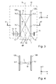
- FIG. 3 shows a schematic representation of the beam path of this embodiment in a first side view
- FIG. 4 a part of the beam path in a second view
- FIG. 5 a plan view of support elements of this device with the deflection elements arranged thereon.
- the device according to the invention comprises a measuring reflector 1 and a number of further components 11-18, which in the present embodiment are arranged in a scanning unit 10 indicated schematically.
- the components 11 - 18 provided in the scanning unit 10 include a light source 16, a collimator optics 17, a detector arrangement 18 and two support elements 12A, 12B, on which further components with optical functionality are arranged; These include, for example, a splitting grid 11, deflecting elements 14.1, 14.2 on the carrier element 12A and a joining element designed as a joining grid 15 as well as further deflecting elements 13.1, 13.2 on the carrier element 12B.
- the measuring reflector 1 is arranged to be variable in distance relative to the scanning unit or to at least part of the other components 11 - 18 along a measuring direction; the measuring direction is denoted by the coordinate z in the figures.
- the measuring reflector 1, on the one hand, and the scanning unit 10, on the other hand may be connected to machine components (not shown) which are movable relative to one another along the measuring direction z.
- Distance signals with respect to the distance or with respect to changes in distance between the measuring reflector 1 and the scanning unit or at least part of the other components 11-18 along the measuring direction z are generated via the device according to the invention for interferential distance measurement. These distance signals can then be further processed by a downstream, also not shown machine control.
- a common scanning unit 10 may be provided in the context of the present invention, for example, to arrange the light source and / or the detector array locally separated from the scanning unit and via optical fibers with the Scanning unit to connect, in which the other components are arranged etc ..
- an interferential optical principle is used in the device according to the invention.
- the scanning beam path of the first embodiment provided for this purpose will be explained in detail below.
- a light source 16 for example formed as a punctiform or nearly punctiform semiconductor laser, emits a beam which is collimated by a collimating optics 17; as an alternative light source is also an LED at this point into consideration.
- the collimated beam then impinges on a splitting element, which is formed as a splitting grid 11 in the form of a transmission phase grating.
- the splitting grating is arranged perpendicular to the measuring reflector 1, ie the grating plane of the splitting grating is perpendicular to the surface of the measuring reflector 1.
- the light source 16 emits the emitted beam parallel to the surface of the measuring reflector 1 in the direction of the splitting grating 11. This direction is shown in the figures designated as x-direction; In the following, let us also talk about the light incidence direction x.
- the collimated bundle of rays incident from the light source 16 is split into a measuring beam M and a reference beam R.
- the splitting grating 11 splits the incident beam into +1. and -1. Diffraction orders, wherein the -1. Diffraction order subsequently acts as a measuring beam M and the +1. Diffraction order as a reference beam R.
- the 0 diffraction order is as completely as possible suppressed by the splitting grating 11.
- the measuring beam M then propagates from the splitting grid 11 in the direction of the measuring reflector 1 and experiences there at a first point of incidence A1 a first reflection in the direction of a first deflecting element 13.1 in the scanning unit 10.
- the arranged on a support member 12B first deflecting element 13.1 is designed as a reflective Fresnel cylindrical lens with additional deflection function in the measuring direction z and exerts certain optical effects on the incident thereon measuring beam M from.
- the measuring beam M incident on the first deflecting element 13.1 experiences a deflecting action along the measuring direction z.
- the measuring beam M incident from the bottom obliquely downwards on the first deflecting element 13.1 is again aligned parallel to the illuminating beam incident on the splitting grid 11.
- the deflected by the first deflecting element 13.1 or reflected measuring beam M thus propagates parallel to the surface of the measuring reflector 1 opposite to the direction of light incidence x in the direction of the second deflecting element 14.1 on the opposite support member 12A.
- the first deflecting element 13.1 exerts on the collimated measuring beam M incident thereon a further optical effect.
- the collimated measuring beam M also experiences a focusing effect on a line focus L via the first deflecting element 13.1, ie the collimated measuring beam M is focused linearly over the first deflecting element 13.1.
- the resulting line focus L extends here - as in particular from FIG. 4 visible - along the measuring direction z and lies exactly in the middle between the two support elements 12A, 12B.
- the two support elements 12A, 12B oriented perpendicular to the measuring reflector 1 are designed as glass plates in the present exemplary embodiment.
- all the elements arranged thereon, ie the different deflecting elements 13.1, 13.2, 14.1, 14.2 and the splitting and joining grids 11, 15, are likewise arranged perpendicular to the surface of the measuring reflector 1.
- the measuring beam M propagates opposite to the light incident direction x then to a second deflection element 14.1, which is arranged on the opposite support member 12A.
- the second deflecting element 14.1 is also formed in the present embodiment as a Fresnel cylindrical lens with additional deflection function in the z-direction, which is identical to the Fresnel cylindrical lens of the first deflecting element 13.1.
- the second deflecting element 14.1 By way of the second deflecting element 14.1, on the one hand, a deflection effect is again exerted on the measuring beam M incident thereon along the measuring direction z in the xz plane.
- the incident from the right to the second deflecting element 14.2 measuring beam is thereby deflected by the second deflecting element 14.2 to the bottom right in the direction of the measuring reflector 1; there it hits the measuring reflector 1 again at a second point of incidence A2.
- the first and second points of incidence A1, A2 of the measuring beam M on the measuring reflector 1 are spaced apart in the light incidence direction x.
- a further optical effect on the incident thereon measuring beam M As from FIG. 4 From the line focus L, a diverging measuring beam M propagates in the direction of the second deflecting element 14.1.
- the second deflecting element 14.1 also exerts a collimating effect on the incident diverging measuring beam M in addition to the deflecting action mentioned, ie in the direction of the second impingement location A2 on the measuring reflector 1 again propagates a collimated measuring beam. M.
- the measurement beam M undergoes a second reflection and finally propagates in the direction of the integration grid 15 in the scanning unit 10.
- Diffraction order resulting reference beam R initially propagates in the direction of a third Deflection element 13.2, which is arranged on the carrier element 12B in the measuring direction z above the first deflecting element 13.1.
- the third deflecting element 13.2 is likewise designed as a Fresnel cylindrical lens with additional deflection function in the z-direction, which in turn is identical to the Fresnel cylindrical lenses of the first and second deflecting elements 13.1, 14.1.
- the third deflecting element 13.2 exerts the identical optical effects on the incident reference beam R as the first deflecting element 13.1 due to identical angles of incidence
- the above-mentioned focusing effect on a line focus in the middle between the carrier elements 12A, 12B on the reference beam R consequently results.
- the reference beam R influenced in this way then propagates to a fourth deflecting element 14.2, which is arranged in the measuring direction z above the second deflecting element 14.1 on the carrier element 12A.
- the fourth deflecting element 14.2 is a reflective Fresnel cylindrical lens with an additional deflecting function in the z direction, which is identical to these three deflecting elements 13.1, 13.2, 14.1.
- the reference beam R incident thereon against the light incidence direction x consequently undergoes a deflection action to the bottom right in the direction of the merging grating 15.
- the reference beam R incident divergently to the fourth deflecting element 14.2 is collimated by it, i.e. by a reference beam. in the direction of the union grating 15 propagates the collimated reference R.
- the reference and measuring beams R, M due to the selected identical design of the deflecting elements 13.1, 13.2, 14.1, 14.2 and their intended arrangement in the scanning unit 10, strike at oppositely symmetrical angles of incidence and arrive at the interfering superimposition.
- phase-shifted distance signals In the case of changes in distance between the measuring reflector 1 and the scanning unit 10 along the measuring direction z, a periodic distance signal which is available for further processing can be detected via the detector arrangement 18 arranged downstream of the joining grid 15.
- the generation of a plurality of phase-shifted distance signals is advantageous. For example, three distance signals each phase-shifted by 120 ° or four distance signals phase-shifted by 90 ° to one another can be generated.
- phase-shifted distance signals are basically various known options available, which can each be used in the device according to the invention.
- phase distance signals can be generated by the land-gap ratio and the etch depth and the phase deviation of the merge grating 15 is suitably selected.
- a generation of four phase-shifted by 90 ° distance signals can also be realized polarization optics.
- suitable polarization-optical components in the beam paths of the measuring beam M and the reference beam R should be arranged.
- the effective measuring point MP on the measuring reflector 1 does not shift with changes in distance along the measuring direction z.
- the plane of symmetry S is according to FIG. 1 as the carrier elements 12A, 12B oriented perpendicular with respect to the measuring reflector 1. How out FIG. 3 Furthermore, it can be seen that the effective measuring point MP lies in the light incident direction x in the middle between the two points of incidence A1, A2 of the measuring beam M on the measuring reflector 1.
- the effective deflection of the deflecting elements 13.1, 13.2, 14.1, 14.2 in the z-direction, ie the focusing elements with deflection function corresponds at each point to a grid with a pitch period of 960nm.
- the distance between the two support elements 12A, 12B in the x direction is chosen to be 12 mm.
- a signal period of the distance signals of 240nm.
- the deflection elements are each arranged perpendicular to the measuring reflector 1.
- the respectively provided diffractive structures of the different variants differ, as will be explained in detail below.
- the beam direction difference between the measuring beam M and the reference beam R depends only on a higher order from a tilt of the measuring reflector MR about the y-axis.
- This means that such tilting of the measuring reflector MR about the y-axis in the present exemplary embodiment of the device according to the invention has only a slight effect on the degree of modulation and the amplitude of the distance signals generated.
- a possible tilting of the measuring reflector MR about the y-axis therefore does not have to be compensated by means of imaging optical elements in the beam path of the measuring beam M; This is required in the present embodiment, only with respect to a possible tilting of the measuring reflector about the x-axis.
- FIG. 7 A slightly modified variant of the first exemplary embodiment of the device according to the invention for interferential distance measurement is shown in FIG. 7 shown schematically. In the following, only the relevant differences from the first embodiment will be explained.
- a diaphragm 19 is arranged.
- the diaphragm 19 prevents any 0th diffraction order resulting from the splitting grating 11 'from passing in the direction of the merge grating 15' and from the resulting constant light component resulting in a deterioration of the modulation depths of the distance signals.
- a cover glass 21 is provided on the underside of the scanning unit 10 ', which faces the measuring reflector 1'.
- a cover glass 21 is provided on the opposite side of the scanning unit 10 '.
- the as in the first embodiment only in the scanning unit 10' propagating reference beam R is after the splitting at the splitting grid 11 ', first a first time reflected on the rear surface reflector 20 before it hits the third deflecting 13.2'. Furthermore, a further deflection of the reference beam R takes place on the rear surface reflector 20 between the fourth deflecting element 14.2 'and the joining grid 15'.
- FIGS. 8, 9a . 9b, 10 and 11 show a schematic representation of the beam path of this embodiment in different views
- FIG. 10 a plan view of the support elements with the thereon arranged on the transmittive Fresnel cylindrical lenses and incident thereon measuring or reference beams M
- R a plan view of the measuring reflector with the different points of incidence of the measuring beam.
- the deflecting elements used in the second exemplary embodiment differ in the beam paths of the measuring and reference beam M, R from those of the first exemplary embodiment.
- the deflecting elements 113.1a, 113.1b, 113.2a, 113.2b, 114.1a, 114.1b, 114.2a, 114.2b are now for a transmittive Fresnel cylindrical lenses, each arranged together with a reflector 120, 121 to the support elements 112A, 112B are.
- These deflecting elements 113.1a, 113.1b, 113.2a, 113.2b, 114.1a, 114.1b, 114.2a, 114.2b designed as transmissive Fresnel cylindrical lenses are arranged on the mutually facing sides of the carrier elements 112A, 112B, the reflectors 120, 121 on the respective opposite sides of the support members 112A, 112B.
- the reflective side of the reflectors 120, 121 is respectively oriented in the direction of the deflecting elements 113.1a, 113.1b, 113.2a, 113.2b, 114.1a, 114.1b, 114.2a, 114.2b designed as transmissive Fresnel cylindrical lenses.
- deflection elements 113.1a, 113.1b, 113.2a, 113.2b, 114.1a, 114.1b, 114.2a, 114.2b of the second exemplary embodiment firstly defined deflection effects are exerted on the radiation beam incident thereon (measurement beam M, reference beam R).
- deflecting 113.1 a, 113.1 b, 113.2a, 113.2b, 114.1 a, 114.1 b, 114.2a, 114.2b a deflection effect on the incident beam in the y-direction and measuring direction z.
- deflecting effects along the measuring direction z and also perpendicular to the measuring direction z are therefore deflecting effects along the measuring direction z and also perpendicular to the measuring direction z.
- the deflection elements 113.2a, 113.2b, 114.2a, 114.2b in the beam path of the reference beam R have corresponding deflection effects in the z-direction and y-direction.
- a focusing effect or a collimating effect on the incident thereon beam results on the deflecting 113.1 a, 113.1 b, 113.2a, 113.2b, 114.1 a, 114.1 b, 114.2a, 114.2b of the second embodiment as above, a focusing effect or a collimating effect on the incident thereon beam.
- collimated beams, incident on the deflection elements 113.1a, 113.2a, 114.1a, 114.2a are linearly focused onto the respectively associated reflector 120, 121; the line focus extends here again along the measuring direction z. Divergent on the deflecting elements 113.1 b, 113.2b, 114.1 b, 114.2b incident beams are collimated on it.
- deflecting elements 122, 123 and 124, 125 are arranged on the carrier elements 112A, 112B, which are designed as reflection gratings and are acted upon by the measuring beam M and the reference beam R as indicated.
- the deflecting elements 122, 123 and 124, 125 in the present embodiment cause only a deflection of the incident thereon radiation beam (measuring beam M, reference beam R) in the xz plane, i. along the measuring direction z; a focusing or collimating optical effect do not exert these deflection elements 122-125 on the radiation beams incident thereon.
- the measuring beam M thus acts four times between the splitting grating 111 and the combining grating 115 on the measuring reflector 100 at the points of incidence A1-A4 as well as the four deflecting elements 113.1a, 113.1b, 114.1a, 114.1b.
- the resulting signal period of the distance signals is halved, i. There is a higher measurement resolution due to the selected beam path available.
- FIG. 14 a plan view of the carrier elements with the deflection elements arranged thereon and the incident thereon measuring or reference beams M
- R R
- FIG. 15 a plan view of the measuring reflector with the impact of the measuring beam on the measuring reflector.
- the following is also indicated in the present third exemplary embodiment with respect to the beam path of the measuring beam M and the reference beam R in which order the different elements of the device according to the invention are acted upon by the measuring beam M and by the reference beam R between the splitting grating 211 and the combining grating 215.
- the Figures 12, 13a . 13b, 14 and 15 directed.
- the third embodiment differs from the previous two embodiments i.w. by the now provided deflection elements 213.1, 213.2, 214.1, 214.2, 222, 223, 224, 225th
- the deflection elements 213.1, 213.2, 214.1, 214.2 are designed as linear reflection phase gratings with inclined graduation lines.
- the radiation beams incident thereon learn about these deflecting elements 213.1, 213.2, 214.1, 214.2 a deflection perpendicular to the measuring direction z in the xy plane and a deflection along the measuring direction z in the xz-level, like this from the views in the FIGS. 12 and 13a is apparent.
- the measurement beam M which comes from the point of impact A1 coming on the deflecting element 213.1, is deflected obliquely downwards in the direction of the impact point A2 on the measuring reflector 200.
- a focusing or collimation of the radiation beam incident thereon does not result via the deflection elements 213.1, 213.2, 214.1, 214.2.
- the further provided deflection elements 222, 223, 224, 225 are formed in this embodiment as a reflective off-axis Fresnel cylindrical lenses. Through them, the beam of rays incident thereon undergoes a deflection along the measuring direction z as well as in the y-direction.
- the deflection element 222 for example, the reference radiation bundle R incident from the deflection element 213.2 is deflected in the direction of the opposite deflection element 225.
- the deflecting elements 222, 223, 224, 225 a focusing or collimating effect when it collides with a collimated or divergent beam.
- the collimated reference beam R incident on the deflecting element 222 is linearly focused in the middle between the carrier elements 212A, 212B; the line focus L extends as if from FIG. 13b in turn, along the measuring direction z.
- the subsequently divergent incident on the deflecting element 225 reference beam R is collimated by this and deflected in the y-direction and in the z-direction in the direction of the deflecting 214.2.
- the measuring beam M again impinges the measuring reflector 200 four times.
- a halved signal period of the distance signals again results.
- FIGS. 16, 17 and 18 show in each case again schematized representations of the beam path of this embodiment in different views; FIG. 18 shows various plan views of several elements of this embodiment.
- the third plate-shaped carrier element 330 which is arranged centrally in the scanning unit 310, to which the two deflecting elements 330.1, 330.2 are now arranged.
- the deflecting elements 330.1, 330.2 are formed in contrast to the previous embodiments as diffractive structures in the form of transmission gratings, which exert certain optical effects on the radiation beam incident thereon.
- the third carrier element 330 is preferably a transparent glass plate, wherein the first deflecting element 330.1 is arranged on the side facing the first carrier element 312A and the second deflecting element 330.2 is on the side facing the second carrier element 312B.
- the scanning unit 310 is closed in the direction of the measuring reflector 300 through a transparent glass plate 340, on the opposite side of the scanning unit 310, a further glass plate 342 is arranged.
- a transparent glass plate 340 on the opposite side of the scanning unit 310, a further glass plate 342 is arranged.
- visible compensation elements 341.1, 341.2 arranged, which are also formed as glass plates with certain thicknesses and each extending between the central third support member 330 and the adjacent support members 312A, 312B; for their function, reference is made to the following description of the scanning beam path of this embodiment.
- the radiation beam emitted by the light source 316 is collimated by a collimating optics 317 analogously to the other embodiments and then impinges on the splitting element, which in turn is formed as a splitting grating 311 in the form of a transmission phase grating and arranged on a first carrier element 312A as in the other embodiments is.
- the splitting grating 311 splits the collimated beam bundle incident from the light source 316 into a measuring beam M and a reference beam R, for which purpose a splitting into +1. and -1. Diffraction orders take place; the 1. Diffraction order subsequently acts as a measuring beam M, the +1. Diffraction order as a reference beam R.
- the 0 diffraction order is as completely as possible suppressed by the splitting grating 311;
- an aperture 350 is placed adjacent to the splitting grating 311 in the scanning unit 310.
- the measuring beam M then propagates from the splitting grating 311 in the direction of the measuring reflector 300 and experiences a first reflection in the direction of the first deflecting element 330.1 in the scanning unit 310 at the first impingement A1.
- the first deflecting element 330.1 arranged on the central carrier element 330 is, as indicated above, a transmissive Fresnel Cylindrical lens formed and exerts certain optical effects on the incident thereon on the measuring beam M.
- the measuring beam M incident on the first deflecting element 330.1 experiences a deflecting action along the measuring direction z.
- the measuring beam M incident from the bottom obliquely on the first deflecting element 330.1 is again aligned parallel to the illuminating beam incident on the splitting grating 311.
- the deflected by the first deflecting element 330.1 or transmitted measurement beam M thus propagates parallel to the surface of the measuring reflector 300 in the light incident direction x in the direction of the second deflection element 330.2 on the opposite side of the central support element 330.
- the first deflecting element 330.1 also exerts a further optical effect on the collimated measuring beam M incident thereon in this exemplary embodiment.
- the collimated measuring beam M also experiences a focusing effect on a line focus L via the first deflecting element 330.1, ie the collimated measuring beam M is focused linearly over the first deflecting element 330.1.
- the resulting line focus L extends here - as out FIG. 17 visible - along the measuring direction z and lies exactly in the middle between the two outer support members 312A, 312B.
- the measuring beam M propagates parallel to the light incident direction x then to a second deflection element 330.2, which is arranged on the opposite side of the third support member 330.
- the second deflecting element 330.2 is likewise designed as a transmittive Fresnel cylindrical lens with an additional deflection function in the z direction, identical to the Fresnel cylindrical lens of the first deflecting element 330.1.
- the second deflecting element 330.2 By way of the second deflecting element 330.2, on the one hand, a deflection effect is again exerted on the measuring beam M incident thereon along the measuring direction z in the xz plane.
- the incident from the left on the second deflecting element 330.2 measuring beam M is thereby deflected by the second deflecting element 330.2 to the bottom right in the direction of the measuring reflector 300; there it hits the measuring reflector 300 again at a second point of incidence A2.
- the first and second points of incidence A1, A2 of the measuring beam M on the measuring reflector 300 are spaced apart in the light incidence direction x.
- the second deflecting element 330.2 turn another optical effect on the incident thereon on the measuring beam M.
- a diverging measuring beam M propagates in the direction of the second deflecting element 330.2.
- the second deflecting element 330.2 furthermore exerts a collimating effect on the incident diverging measuring beam M in addition to the aforementioned deflecting effect, ie in the direction of the second impinging location A2 on the measuring reflector 300 again propagates a collimated measuring beam. M.
- the measuring beam M undergoes a second reflection and finally propagates in the direction of the unifying element, formed as unification grating 315, in the scanning unit 310.
- the combining grating 315 is arranged on the second carrier element 312B as in the previous embodiments.
- the two support elements 312A, 312B oriented perpendicularly to the measurement reflector 300 are designed as glass plates analogously to the preceding embodiments, as is the additional third support element 330 provided here. Due to the orientation of the support elements 312A, 312B and 330, all the elements arranged thereon, i. the various deflection elements 330.1, 330.2 and the splitting and joining grids 311, 315, also arranged perpendicular to the surface of the measuring reflector 300.
- the first deflecting element 330.1 exerts the identical optical effects on the incident reference beam R as explained above on the measuring beam MP incident thereon, in addition to the deflection effect along the measuring direction z above-mentioned focusing effect on a line focus L in the center of the third support member 330.
- the reference beam R influenced in this way then propagates to the second deflecting element 330.2, which is arranged on the opposite side of the third carrier element 330.
- the reference beam R incident thereon parallel to the direction of light incidence x thus again results in a deflection action to the right in the direction of the merger grating 315.
- the reference beam R incident divergently to the second deflecting element 330.2 is collimated by it, i.e. by a reference beam. in the direction of the union grating 315 propagates the collimated reference R.
- the reference beam R propagates between the splitting grating 311 and the combining grating 315 exclusively in the scanning unit 310.
- the reference and measuring beams R, M impinge at opposite symmetrical angles of incidence, where they reach the interfering superimposition.
- a periodic distance signal which is available for further processing, can be detected via the detector arrangement 318 located downstream of the combining grating 315.
- the generation of a plurality of phase-shifted distance signals is advantageous.
- three distance signals each phase-shifted by 120 ° or four distance signals phase-shifted by 90 ° to each other can be generated; For this purpose, reference is also made to our statements above.
- the measuring beam M passes between the splitting grating 311 and the joining grating 315 four times the glass plate 340, which terminates the scanning unit 310 in the direction of the measuring reflector 300.
- two compensating elements 341.1, 341.2 are also arranged in the form of glass plates in the beam path of the reference beam R in the scanning unit. Since the reference beam R passes through the compensating element 341.1 exactly once and the compensating element 341.2 likewise once, the compensating elements 341.1, 341.2 each have twice the thickness of the glass plate 340.
- the measuring and reference beams M, R pass through identical glass paths in the scanning unit 310; Phase differences in the beam bundles M, R result exclusively due to changes in the distance between the measuring reflector 300 and the scanning unit 310, since in this case the measuring beam M shifts relative to the deflecting elements 330.1, 330.2.
- first and second deflecting elements 330.1, 330.2 each in two parts, i. not as a single transmission grating extending in the z-direction, but in the form of two transmission gratings, which are provided only locally in the region of the points of impingement of the measurement and reference beams M, R.
- the deflecting elements 330.1, 330.2 separately on two thin glass plates which are placed oriented perpendicular to the measuring reflector 300 on the left and right of the symmetry center of the arrangement. The distance between these two glass plates would then be selected such that the optical paths of the radiation beams between the first and second deflecting elements 330.1, 330.2 would be identical to the case of the embodiment described above with the thick glass plate 330.
- the same imaging optical elements or optical functionalities are provided in the deflecting elements as in the measuring beam for reasons of symmetry in the beam path of the reference beam. Since a tilting of the measuring reflector has no influence on the reference beam, in further possible embodiments the deflecting elements in the beam path of the reference beam may also be designed as purely deflecting elements without additional optical functionality.
- the joining element need not be formed as a joining grid as shown in the various embodiments. It would also be conceivable in principle in the context of the present invention, as a unifying element, e.g. to provide a suitable beam splitter at this point.
- beam paths can be realized in which the light source and the gratings are located virtually in the same places as in the exemplary embodiments described here. This could e.g. be achieved by additional reflective elements in the beam path etc ..
Landscapes
- Physics & Mathematics (AREA)
- General Physics & Mathematics (AREA)
- Length Measuring Devices By Optical Means (AREA)
- Optical Transform (AREA)
- Instruments For Measurement Of Length By Optical Means (AREA)
Applications Claiming Priority (2)
| Application Number | Priority Date | Filing Date | Title |
|---|---|---|---|
| DE102012210079 | 2012-06-15 | ||
| DE102013203211A DE102013203211A1 (de) | 2012-06-15 | 2013-02-27 | Vorrichtung zur interferentiellen Abstandsmessung |
Publications (2)
| Publication Number | Publication Date |
|---|---|
| EP2674720A1 true EP2674720A1 (fr) | 2013-12-18 |
| EP2674720B1 EP2674720B1 (fr) | 2021-04-14 |
Family
ID=48482975
Family Applications (1)
| Application Number | Title | Priority Date | Filing Date |
|---|---|---|---|
| EP13169449.9A Active EP2674720B1 (fr) | 2012-06-15 | 2013-05-28 | Dispositif de mesure de distance interférentielle |
Country Status (5)
| Country | Link |
|---|---|
| US (1) | US9400168B2 (fr) |
| EP (1) | EP2674720B1 (fr) |
| JP (1) | JP6181978B2 (fr) |
| CN (1) | CN103512505B (fr) |
| DE (1) | DE102013203211A1 (fr) |
Cited By (2)
| Publication number | Priority date | Publication date | Assignee | Title |
|---|---|---|---|---|
| CN105043280A (zh) * | 2015-05-18 | 2015-11-11 | 北京理工大学 | 一种回转中心测量装置及其间距测量方法 |
| CN107702657A (zh) * | 2017-10-31 | 2018-02-16 | 北京汽车研究总院有限公司 | 一种间距测量装置 |
Families Citing this family (7)
| Publication number | Priority date | Publication date | Assignee | Title |
|---|---|---|---|---|
| DE102013206693A1 (de) | 2013-04-15 | 2014-10-16 | Dr. Johannes Heidenhain Gmbh | Vorrichtung zur interferentiellen Abstandsmessung |
| DE102013220214A1 (de) | 2013-10-07 | 2015-04-09 | Dr. Johannes Heidenhain Gmbh | Anordnung zur Positionierung eines Werkzeugs relativ zu einem Werkstück |
| TWI627379B (zh) * | 2013-10-07 | 2018-06-21 | 德商強那斯海登翰博士有限公司 | 光學位置測量裝置 |
| DE102013221898A1 (de) | 2013-10-29 | 2015-04-30 | Dr. Johannes Heidenhain Gmbh | Vorrichtung zur Positionsbestimmung |
| JP6322069B2 (ja) * | 2014-07-02 | 2018-05-09 | Dmg森精機株式会社 | 変位検出装置 |
| FR3026836B1 (fr) * | 2014-10-03 | 2022-04-22 | Centre Nat Rech Scient | Methode et dispositif optique de telemetrie |
| DE102017115922C5 (de) * | 2017-07-14 | 2023-03-23 | Precitec Gmbh & Co. Kg | Verfahren und Vorrichtung zur Messung und Einstellung eines Abstands zwischen einem Bearbeitungskopf und einem Werkstück sowie dazugehöriges Verfahren zur Regelung |
Citations (5)
| Publication number | Priority date | Publication date | Assignee | Title |
|---|---|---|---|---|
| DE9007809U1 (de) * | 1989-12-23 | 1996-12-05 | Dr. Johannes Heidenhain Gmbh, 83301 Traunreut | Positionsmeßeinrichtung |
| GB2443662A (en) * | 2006-11-09 | 2008-05-14 | Firecomms Ltd | Laser motion detector |
| DE102007016774A1 (de) | 2007-04-04 | 2008-10-09 | Friedrich-Schiller-Universität Jena | Verfahren und Vorrichtung zur interferenziellen Abstandsmessung von Objekten |
| US7505144B2 (en) * | 1996-01-24 | 2009-03-17 | Kla-Tencor Technologies Corporation | Copper CMP flatness monitor using grazing incidence interferometry |
| DE102010003157A1 (de) | 2010-03-23 | 2011-09-29 | Dr. Johannes Heidenhain Gmbh | Vorrichtung zur interferentiellen Abstandsmessung |
Family Cites Families (11)
| Publication number | Priority date | Publication date | Assignee | Title |
|---|---|---|---|---|
| JP2546364B2 (ja) * | 1988-02-16 | 1996-10-23 | キヤノン株式会社 | 位置合わせ装置 |
| DE58907622D1 (de) | 1989-12-23 | 1994-06-09 | Heidenhain Gmbh Dr Johannes | Positionsmesseinrichtung. |
| US5196902A (en) * | 1991-10-09 | 1993-03-23 | Advanced Fuel Research, Inc. | Two-beam interferometer apparatus and method, and spectrometer utilizing the same |
| US5654798A (en) * | 1995-01-19 | 1997-08-05 | Tropel Corporation | Interferometric measurement of surfaces with diffractive optics at grazing incidence |
| US5793488A (en) * | 1995-07-31 | 1998-08-11 | Tropel Corporation | Interferometer with compound optics for measuring cylindrical objects at oblique incidence |
| US6249351B1 (en) * | 1999-06-03 | 2001-06-19 | Zygo Corporation | Grazing incidence interferometer and method |
| JP5340539B2 (ja) * | 2003-09-15 | 2013-11-13 | ザイゴ コーポレーション | 表面の干渉分析のための方法およびシステムならびに関連する応用例 |
| US8922781B2 (en) * | 2004-11-29 | 2014-12-30 | The General Hospital Corporation | Arrangements, devices, endoscopes, catheters and methods for performing optical imaging by simultaneously illuminating and detecting multiple points on a sample |
| JP5553635B2 (ja) * | 2009-10-23 | 2014-07-16 | キヤノン株式会社 | 補償光学装置、撮像装置および補償光学方法、撮像方法 |
| JP2011203245A (ja) * | 2010-03-02 | 2011-10-13 | You-Na Tech Corp | 半導体ウェハの表面検査システム及び表面検査方法 |
| CN102353327A (zh) * | 2011-06-27 | 2012-02-15 | 中国人民解放军国防科学技术大学 | 双频激光光栅干涉测量方法及测量系统 |
-
2013
- 2013-02-27 DE DE102013203211A patent/DE102013203211A1/de not_active Withdrawn
- 2013-05-28 JP JP2013111986A patent/JP6181978B2/ja active Active
- 2013-05-28 EP EP13169449.9A patent/EP2674720B1/fr active Active
- 2013-06-13 US US13/916,753 patent/US9400168B2/en not_active Expired - Fee Related
- 2013-06-17 CN CN201310238005.3A patent/CN103512505B/zh active Active
Patent Citations (5)
| Publication number | Priority date | Publication date | Assignee | Title |
|---|---|---|---|---|
| DE9007809U1 (de) * | 1989-12-23 | 1996-12-05 | Dr. Johannes Heidenhain Gmbh, 83301 Traunreut | Positionsmeßeinrichtung |
| US7505144B2 (en) * | 1996-01-24 | 2009-03-17 | Kla-Tencor Technologies Corporation | Copper CMP flatness monitor using grazing incidence interferometry |
| GB2443662A (en) * | 2006-11-09 | 2008-05-14 | Firecomms Ltd | Laser motion detector |
| DE102007016774A1 (de) | 2007-04-04 | 2008-10-09 | Friedrich-Schiller-Universität Jena | Verfahren und Vorrichtung zur interferenziellen Abstandsmessung von Objekten |
| DE102010003157A1 (de) | 2010-03-23 | 2011-09-29 | Dr. Johannes Heidenhain Gmbh | Vorrichtung zur interferentiellen Abstandsmessung |
Cited By (4)
| Publication number | Priority date | Publication date | Assignee | Title |
|---|---|---|---|---|
| CN105043280A (zh) * | 2015-05-18 | 2015-11-11 | 北京理工大学 | 一种回转中心测量装置及其间距测量方法 |
| CN105043280B (zh) * | 2015-05-18 | 2018-03-09 | 北京理工大学 | 一种回转中心间距测量方法 |
| CN107702657A (zh) * | 2017-10-31 | 2018-02-16 | 北京汽车研究总院有限公司 | 一种间距测量装置 |
| CN107702657B (zh) * | 2017-10-31 | 2024-03-22 | 北京汽车集团越野车有限公司 | 一种间距测量装置 |
Also Published As
| Publication number | Publication date |
|---|---|
| JP6181978B2 (ja) | 2017-08-16 |
| JP2014002139A (ja) | 2014-01-09 |
| CN103512505B (zh) | 2017-05-10 |
| US9400168B2 (en) | 2016-07-26 |
| CN103512505A (zh) | 2014-01-15 |
| US20130335746A1 (en) | 2013-12-19 |
| DE102013203211A1 (de) | 2013-12-19 |
| EP2674720B1 (fr) | 2021-04-14 |
Similar Documents
| Publication | Publication Date | Title |
|---|---|---|
| EP2674720B1 (fr) | Dispositif de mesure de distance interférentielle | |
| EP2660566B1 (fr) | Codeur optique pour déterminer la position de deux parties deplaçable l'une par rapport à l'autre dans deux directions de déplacement | |
| DE102010003157B4 (de) | Vorrichtung zur interferentiellen Abstandsmessung | |
| EP1923673B1 (fr) | Dispositif de mesure de position | |
| EP2848899B1 (fr) | Dispositif optique de mesure de position | |
| EP1901041A2 (fr) | Dispositif de mesure de position | |
| DE102017110049A1 (de) | Verschiebungserkennungsvorrichtung | |
| EP2474815A1 (fr) | Dispositif optique de mesure de la position | |
| EP2623937B1 (fr) | Dispositif de mesure de position et agencement à plusieurs dispositifs de mesure de position | |
| EP2857802B1 (fr) | Dispositif optique de mesure de position | |
| DE19930687B4 (de) | Optisches Verschiebungsmeßsystem | |
| EP3059554B1 (fr) | Dispositif optique de mesure de position | |
| EP2565578B1 (fr) | Dispositif interférométrique de détermination de distance entre deux plaques parallèles | |
| EP2746731B1 (fr) | Dispositif optique de mesure de la position | |
| EP3477264B1 (fr) | Dispositif optique de mesure de position | |
| DE102011005937B4 (de) | Vorrichtung zur interferentiellen Abstandsmessung | |
| EP2869034B1 (fr) | Dispositif de détermination de la position | |
| DE112014001977B4 (de) | Vorrichtung zur interferentiellen Abstandsmessung | |
| EP3869161B1 (fr) | Dispositif optique de mesure de position | |
| EP3045873B1 (fr) | Dispositif optique de mesure de position | |
| EP2356405B1 (fr) | Dispositif de mesure de position optique | |
| DE3928064A1 (de) | Lichtelektrische positionsmesseinrichtung |
Legal Events
| Date | Code | Title | Description |
|---|---|---|---|
| PUAI | Public reference made under article 153(3) epc to a published international application that has entered the european phase |
Free format text: ORIGINAL CODE: 0009012 |
|
| AK | Designated contracting states |
Kind code of ref document: A1 Designated state(s): AL AT BE BG CH CY CZ DE DK EE ES FI FR GB GR HR HU IE IS IT LI LT LU LV MC MK MT NL NO PL PT RO RS SE SI SK SM TR |
|
| AX | Request for extension of the european patent |
Extension state: BA ME |
|
| 17P | Request for examination filed |
Effective date: 20140618 |
|
| RBV | Designated contracting states (corrected) |
Designated state(s): AL AT BE BG CH CY CZ DE DK EE ES FI FR GB GR HR HU IE IS IT LI LT LU LV MC MK MT NL NO PL PT RO RS SE SI SK SM TR |
|
| STAA | Information on the status of an ep patent application or granted ep patent |
Free format text: STATUS: EXAMINATION IS IN PROGRESS |
|
| 17Q | First examination report despatched |
Effective date: 20181005 |
|
| GRAP | Despatch of communication of intention to grant a patent |
Free format text: ORIGINAL CODE: EPIDOSNIGR1 |
|
| STAA | Information on the status of an ep patent application or granted ep patent |
Free format text: STATUS: GRANT OF PATENT IS INTENDED |
|
| RIC1 | Information provided on ipc code assigned before grant |
Ipc: G01B 9/02 20060101AFI20201028BHEP Ipc: G01B 11/02 20060101ALI20201028BHEP |
|
| INTG | Intention to grant announced |
Effective date: 20201111 |
|
| GRAS | Grant fee paid |
Free format text: ORIGINAL CODE: EPIDOSNIGR3 |
|
| GRAA | (expected) grant |
Free format text: ORIGINAL CODE: 0009210 |
|
| STAA | Information on the status of an ep patent application or granted ep patent |
Free format text: STATUS: THE PATENT HAS BEEN GRANTED |
|
| AK | Designated contracting states |
Kind code of ref document: B1 Designated state(s): AL AT BE BG CH CY CZ DE DK EE ES FI FR GB GR HR HU IE IS IT LI LT LU LV MC MK MT NL NO PL PT RO RS SE SI SK SM TR |
|
| REG | Reference to a national code |
Ref country code: GB Ref legal event code: FG4D Free format text: NOT ENGLISH |
|
| REG | Reference to a national code |
Ref country code: CH Ref legal event code: EP |
|
| REG | Reference to a national code |
Ref country code: DE Ref legal event code: R096 Ref document number: 502013015645 Country of ref document: DE |
|
| REG | Reference to a national code |
Ref country code: IE Ref legal event code: FG4D Free format text: LANGUAGE OF EP DOCUMENT: GERMAN |
|
| REG | Reference to a national code |
Ref country code: AT Ref legal event code: REF Ref document number: 1382794 Country of ref document: AT Kind code of ref document: T Effective date: 20210515 |
|
| REG | Reference to a national code |
Ref country code: LT Ref legal event code: MG9D |
|
| REG | Reference to a national code |
Ref country code: NL Ref legal event code: MP Effective date: 20210414 |
|
| PG25 | Lapsed in a contracting state [announced via postgrant information from national office to epo] |
Ref country code: HR Free format text: LAPSE BECAUSE OF FAILURE TO SUBMIT A TRANSLATION OF THE DESCRIPTION OR TO PAY THE FEE WITHIN THE PRESCRIBED TIME-LIMIT Effective date: 20210414 Ref country code: BG Free format text: LAPSE BECAUSE OF FAILURE TO SUBMIT A TRANSLATION OF THE DESCRIPTION OR TO PAY THE FEE WITHIN THE PRESCRIBED TIME-LIMIT Effective date: 20210714 Ref country code: LT Free format text: LAPSE BECAUSE OF FAILURE TO SUBMIT A TRANSLATION OF THE DESCRIPTION OR TO PAY THE FEE WITHIN THE PRESCRIBED TIME-LIMIT Effective date: 20210414 Ref country code: NL Free format text: LAPSE BECAUSE OF FAILURE TO SUBMIT A TRANSLATION OF THE DESCRIPTION OR TO PAY THE FEE WITHIN THE PRESCRIBED TIME-LIMIT Effective date: 20210414 Ref country code: FI Free format text: LAPSE BECAUSE OF FAILURE TO SUBMIT A TRANSLATION OF THE DESCRIPTION OR TO PAY THE FEE WITHIN THE PRESCRIBED TIME-LIMIT Effective date: 20210414 |
|
| PG25 | Lapsed in a contracting state [announced via postgrant information from national office to epo] |
Ref country code: PL Free format text: LAPSE BECAUSE OF FAILURE TO SUBMIT A TRANSLATION OF THE DESCRIPTION OR TO PAY THE FEE WITHIN THE PRESCRIBED TIME-LIMIT Effective date: 20210414 Ref country code: NO Free format text: LAPSE BECAUSE OF FAILURE TO SUBMIT A TRANSLATION OF THE DESCRIPTION OR TO PAY THE FEE WITHIN THE PRESCRIBED TIME-LIMIT Effective date: 20210714 Ref country code: PT Free format text: LAPSE BECAUSE OF FAILURE TO SUBMIT A TRANSLATION OF THE DESCRIPTION OR TO PAY THE FEE WITHIN THE PRESCRIBED TIME-LIMIT Effective date: 20210816 Ref country code: ES Free format text: LAPSE BECAUSE OF FAILURE TO SUBMIT A TRANSLATION OF THE DESCRIPTION OR TO PAY THE FEE WITHIN THE PRESCRIBED TIME-LIMIT Effective date: 20210414 Ref country code: IS Free format text: LAPSE BECAUSE OF FAILURE TO SUBMIT A TRANSLATION OF THE DESCRIPTION OR TO PAY THE FEE WITHIN THE PRESCRIBED TIME-LIMIT Effective date: 20210814 Ref country code: GR Free format text: LAPSE BECAUSE OF FAILURE TO SUBMIT A TRANSLATION OF THE DESCRIPTION OR TO PAY THE FEE WITHIN THE PRESCRIBED TIME-LIMIT Effective date: 20210715 Ref country code: LV Free format text: LAPSE BECAUSE OF FAILURE TO SUBMIT A TRANSLATION OF THE DESCRIPTION OR TO PAY THE FEE WITHIN THE PRESCRIBED TIME-LIMIT Effective date: 20210414 Ref country code: RS Free format text: LAPSE BECAUSE OF FAILURE TO SUBMIT A TRANSLATION OF THE DESCRIPTION OR TO PAY THE FEE WITHIN THE PRESCRIBED TIME-LIMIT Effective date: 20210414 Ref country code: SE Free format text: LAPSE BECAUSE OF FAILURE TO SUBMIT A TRANSLATION OF THE DESCRIPTION OR TO PAY THE FEE WITHIN THE PRESCRIBED TIME-LIMIT Effective date: 20210414 |
|
| REG | Reference to a national code |
Ref country code: CH Ref legal event code: PL |
|
| REG | Reference to a national code |
Ref country code: DE Ref legal event code: R097 Ref document number: 502013015645 Country of ref document: DE |
|
| PG25 | Lapsed in a contracting state [announced via postgrant information from national office to epo] |
Ref country code: SM Free format text: LAPSE BECAUSE OF FAILURE TO SUBMIT A TRANSLATION OF THE DESCRIPTION OR TO PAY THE FEE WITHIN THE PRESCRIBED TIME-LIMIT Effective date: 20210414 Ref country code: SK Free format text: LAPSE BECAUSE OF FAILURE TO SUBMIT A TRANSLATION OF THE DESCRIPTION OR TO PAY THE FEE WITHIN THE PRESCRIBED TIME-LIMIT Effective date: 20210414 Ref country code: DK Free format text: LAPSE BECAUSE OF FAILURE TO SUBMIT A TRANSLATION OF THE DESCRIPTION OR TO PAY THE FEE WITHIN THE PRESCRIBED TIME-LIMIT Effective date: 20210414 Ref country code: CZ Free format text: LAPSE BECAUSE OF FAILURE TO SUBMIT A TRANSLATION OF THE DESCRIPTION OR TO PAY THE FEE WITHIN THE PRESCRIBED TIME-LIMIT Effective date: 20210414 Ref country code: EE Free format text: LAPSE BECAUSE OF FAILURE TO SUBMIT A TRANSLATION OF THE DESCRIPTION OR TO PAY THE FEE WITHIN THE PRESCRIBED TIME-LIMIT Effective date: 20210414 Ref country code: RO Free format text: LAPSE BECAUSE OF FAILURE TO SUBMIT A TRANSLATION OF THE DESCRIPTION OR TO PAY THE FEE WITHIN THE PRESCRIBED TIME-LIMIT Effective date: 20210414 Ref country code: LU Free format text: LAPSE BECAUSE OF NON-PAYMENT OF DUE FEES Effective date: 20210528 Ref country code: LI Free format text: LAPSE BECAUSE OF NON-PAYMENT OF DUE FEES Effective date: 20210531 Ref country code: MC Free format text: LAPSE BECAUSE OF FAILURE TO SUBMIT A TRANSLATION OF THE DESCRIPTION OR TO PAY THE FEE WITHIN THE PRESCRIBED TIME-LIMIT Effective date: 20210414 Ref country code: CH Free format text: LAPSE BECAUSE OF NON-PAYMENT OF DUE FEES Effective date: 20210531 |
|
| REG | Reference to a national code |
Ref country code: BE Ref legal event code: MM Effective date: 20210531 |
|
| PLBE | No opposition filed within time limit |
Free format text: ORIGINAL CODE: 0009261 |
|
| STAA | Information on the status of an ep patent application or granted ep patent |
Free format text: STATUS: NO OPPOSITION FILED WITHIN TIME LIMIT |
|
| 26N | No opposition filed |
Effective date: 20220117 |
|
| GBPC | Gb: european patent ceased through non-payment of renewal fee |
Effective date: 20210714 |
|
| PG25 | Lapsed in a contracting state [announced via postgrant information from national office to epo] |
Ref country code: IE Free format text: LAPSE BECAUSE OF NON-PAYMENT OF DUE FEES Effective date: 20210528 Ref country code: GB Free format text: LAPSE BECAUSE OF NON-PAYMENT OF DUE FEES Effective date: 20210714 |
|
| PG25 | Lapsed in a contracting state [announced via postgrant information from national office to epo] |
Ref country code: IS Free format text: LAPSE BECAUSE OF FAILURE TO SUBMIT A TRANSLATION OF THE DESCRIPTION OR TO PAY THE FEE WITHIN THE PRESCRIBED TIME-LIMIT Effective date: 20210814 Ref country code: FR Free format text: LAPSE BECAUSE OF NON-PAYMENT OF DUE FEES Effective date: 20210614 Ref country code: AL Free format text: LAPSE BECAUSE OF FAILURE TO SUBMIT A TRANSLATION OF THE DESCRIPTION OR TO PAY THE FEE WITHIN THE PRESCRIBED TIME-LIMIT Effective date: 20210414 |
|
| REG | Reference to a national code |
Ref country code: AT Ref legal event code: MM01 Ref document number: 1382794 Country of ref document: AT Kind code of ref document: T Effective date: 20210528 |
|
| PG25 | Lapsed in a contracting state [announced via postgrant information from national office to epo] |
Ref country code: IT Free format text: LAPSE BECAUSE OF FAILURE TO SUBMIT A TRANSLATION OF THE DESCRIPTION OR TO PAY THE FEE WITHIN THE PRESCRIBED TIME-LIMIT Effective date: 20210414 Ref country code: BE Free format text: LAPSE BECAUSE OF NON-PAYMENT OF DUE FEES Effective date: 20210531 |
|
| PG25 | Lapsed in a contracting state [announced via postgrant information from national office to epo] |
Ref country code: AT Free format text: LAPSE BECAUSE OF NON-PAYMENT OF DUE FEES Effective date: 20210528 |
|
| PG25 | Lapsed in a contracting state [announced via postgrant information from national office to epo] |
Ref country code: HU Free format text: LAPSE BECAUSE OF FAILURE TO SUBMIT A TRANSLATION OF THE DESCRIPTION OR TO PAY THE FEE WITHIN THE PRESCRIBED TIME-LIMIT; INVALID AB INITIO Effective date: 20130528 |
|
| PG25 | Lapsed in a contracting state [announced via postgrant information from national office to epo] |
Ref country code: CY Free format text: LAPSE BECAUSE OF FAILURE TO SUBMIT A TRANSLATION OF THE DESCRIPTION OR TO PAY THE FEE WITHIN THE PRESCRIBED TIME-LIMIT Effective date: 20210414 |
|
| PG25 | Lapsed in a contracting state [announced via postgrant information from national office to epo] |
Ref country code: MK Free format text: LAPSE BECAUSE OF FAILURE TO SUBMIT A TRANSLATION OF THE DESCRIPTION OR TO PAY THE FEE WITHIN THE PRESCRIBED TIME-LIMIT Effective date: 20210414 |
|
| PG25 | Lapsed in a contracting state [announced via postgrant information from national office to epo] |
Ref country code: TR Free format text: LAPSE BECAUSE OF FAILURE TO SUBMIT A TRANSLATION OF THE DESCRIPTION OR TO PAY THE FEE WITHIN THE PRESCRIBED TIME-LIMIT Effective date: 20210414 |
|
| PGFP | Annual fee paid to national office [announced via postgrant information from national office to epo] |
Ref country code: DE Payment date: 20240521 Year of fee payment: 12 |