EP2674675B1 - Heizgerät mit Rekuperator und Abgasadapter - Google Patents
Heizgerät mit Rekuperator und Abgasadapter Download PDFInfo
- Publication number
- EP2674675B1 EP2674675B1 EP13170551.9A EP13170551A EP2674675B1 EP 2674675 B1 EP2674675 B1 EP 2674675B1 EP 13170551 A EP13170551 A EP 13170551A EP 2674675 B1 EP2674675 B1 EP 2674675B1
- Authority
- EP
- European Patent Office
- Prior art keywords
- exhaust
- recuperator
- adapter
- pipe connection
- exhaust pipe
- Prior art date
- Legal status (The legal status is an assumption and is not a legal conclusion. Google has not performed a legal analysis and makes no representation as to the accuracy of the status listed.)
- Active
Links
Images

Classifications
-
- F—MECHANICAL ENGINEERING; LIGHTING; HEATING; WEAPONS; BLASTING
- F23—COMBUSTION APPARATUS; COMBUSTION PROCESSES
- F23J—REMOVAL OR TREATMENT OF COMBUSTION PRODUCTS OR COMBUSTION RESIDUES; FLUES
- F23J13/00—Fittings for chimneys or flues
- F23J13/02—Linings; Jackets; Casings
- F23J13/025—Linings; Jackets; Casings composed of concentric elements, e.g. double walled
-
- F—MECHANICAL ENGINEERING; LIGHTING; HEATING; WEAPONS; BLASTING
- F23—COMBUSTION APPARATUS; COMBUSTION PROCESSES
- F23J—REMOVAL OR TREATMENT OF COMBUSTION PRODUCTS OR COMBUSTION RESIDUES; FLUES
- F23J13/00—Fittings for chimneys or flues
- F23J13/04—Joints; Connections
-
- F—MECHANICAL ENGINEERING; LIGHTING; HEATING; WEAPONS; BLASTING
- F23—COMBUSTION APPARATUS; COMBUSTION PROCESSES
- F23J—REMOVAL OR TREATMENT OF COMBUSTION PRODUCTS OR COMBUSTION RESIDUES; FLUES
- F23J15/00—Arrangements of devices for treating smoke or fumes
- F23J15/06—Arrangements of devices for treating smoke or fumes of coolers
-
- F—MECHANICAL ENGINEERING; LIGHTING; HEATING; WEAPONS; BLASTING
- F28—HEAT EXCHANGE IN GENERAL
- F28D—HEAT-EXCHANGE APPARATUS, NOT PROVIDED FOR IN ANOTHER SUBCLASS, IN WHICH THE HEAT-EXCHANGE MEDIA DO NOT COME INTO DIRECT CONTACT
- F28D21/00—Heat-exchange apparatus not covered by any of the groups F28D1/00 - F28D20/00
- F28D21/0001—Recuperative heat exchangers
- F28D21/0003—Recuperative heat exchangers the heat being recuperated from exhaust gases
- F28D21/0005—Recuperative heat exchangers the heat being recuperated from exhaust gases for domestic or space-heating systems
- F28D21/0007—Water heaters
-
- F—MECHANICAL ENGINEERING; LIGHTING; HEATING; WEAPONS; BLASTING
- F23—COMBUSTION APPARATUS; COMBUSTION PROCESSES
- F23J—REMOVAL OR TREATMENT OF COMBUSTION PRODUCTS OR COMBUSTION RESIDUES; FLUES
- F23J2211/00—Flue gas duct systems
- F23J2211/10—Balanced flues (combining air supply and flue gas exhaust)
- F23J2211/101—Balanced flues (combining air supply and flue gas exhaust) with coaxial duct arrangement
-
- F—MECHANICAL ENGINEERING; LIGHTING; HEATING; WEAPONS; BLASTING
- F23—COMBUSTION APPARATUS; COMBUSTION PROCESSES
- F23J—REMOVAL OR TREATMENT OF COMBUSTION PRODUCTS OR COMBUSTION RESIDUES; FLUES
- F23J2213/00—Chimneys or flues
- F23J2213/20—Joints; Connections
- F23J2213/203—Joints; Connections between stack/duct and combustion apparatus
-
- F—MECHANICAL ENGINEERING; LIGHTING; HEATING; WEAPONS; BLASTING
- F24—HEATING; RANGES; VENTILATING
- F24D—DOMESTIC- OR SPACE-HEATING SYSTEMS, e.g. CENTRAL HEATING SYSTEMS; DOMESTIC HOT-WATER SUPPLY SYSTEMS; ELEMENTS OR COMPONENTS THEREFOR
- F24D2200/00—Heat sources or energy sources
- F24D2200/16—Waste heat
- F24D2200/18—Flue gas recuperation
Definitions
- Fuel-operated heaters with recuperators to increase efficiency are known from the prior art.
- the exhaust gas of a heating burner which has been cooled in a first heat exchanger, further cooled by means of cold process water. While by means of heating water, the exhaust gas can be minimally cooled to the heating return temperature, the waste gas can be cooled down to a minimum of the temperature of the cold process water during process water cooling.
- Heaters with recuperators are known from the prior art.
- a conventional, wall-mounted heater can be supplemented by a recuperator, which is mounted between the heater and the wall, so that the heater is attached to the wall-mounted recuperator. This creates a compact unit with few attachment points on the wall.
- the invention has for its object to provide a compact connection for a gas-fired heater with recuperator, by means of which existing installations can be used.
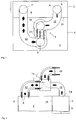
- FIGS. 1 to 3 show from above, the side and from behind a fuel-fired heater 2, which is connected to its heater housing 3 to a recuperator 5 of a recuperator 4 via the recuperator front 10 via fastening means not shown in detail.
- a fuel-fired heater 2 which is connected to its heater housing 3 to a recuperator 5 of a recuperator 4 via the recuperator front 10 via fastening means not shown in detail.
- At the Rekuperator Wegwand 9 not shown in detail means are mounted on the wall.
- the heater 2 has an upwardly directed Schuungsabgasrohran gleich 6, the recuperator 4 via an exhaust gas inlet 7 and an exhaust outlet 8.
- An exhaust gas adapter 1 connects the Schuungsabgasrohran gleich 6 of the heater 2 with the exhaust gas inlet 7 of the recuperator 4 and the exhaust gas outlet 8 of the recuperator 4 with a Adapter exhaust pipe connection 11, wherein the direction of the mouth of the Edelungsabgasrohran gleiches 6 and the direction of the mouth of the AdapterabrohrrohranInstitutes 11 form a right angle and also lie in a plane perpendicular to the Rekuperatorschreibwand 9.
- the exhaust gas adapter 1 which connects the heater exhaust pipe connection 6 with the exhaust gas inlet 7 of the recuperator 4 and the exhaust gas outlet 8 of the recuperator 4 with the adapter exhaust pipe connection 11 by means of exhaust pipes 12, surrounds - as in FIGS FIGS. 1 to 3 shown - this exhaust pipes 12 fresh air.
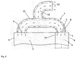
- the exhaust adapter 1 connect the Schuungsabgasrohran gleich 6 with the exhaust gas inlet 7 of the recuperator 4 and the exhaust outlet 8 of the recuperator 4 with the adapter exhaust pipe 11 in coaxial lines, the exhaust pipes 12 are surrounded by fresh air ducts 13
- the exhaust gas adapter 1 has the same extent as a standard exhaust gas bend from the inlet connectable to the heating exhaust gas pipe connection 6 to the adapter exhaust gas pipe connection 11. This ensures that standard exhaust pipes can be used to connect the combination of heater 2 and recuperator 4 use.
- the exhaust adapter 1 has from the connectable to the Walkerungsabgasrohran gleich 6 entrance to the adapter exhaust pipe 11 over the same horizontal extent as the sum of the depth t of the Rekuperatorgeophuses 5, resulting from the distance between Rekuperator Wegwand 9 and Rekuperatorvorderseite 10, plus a standard exhaust bend.
- a simple supplement is possible.
- a mounted heater 2 can be dismantled, connected to the recuperator 4 and connected via the exhaust adapter 1 again with the existing exhaust pipe.
- For a new installation standard components can be used.
- the exhaust gases of the heating device 2 which have delivered thermal energy to a heating circuit in a primary heat exchanger, not shown, and thus minimized to heating return temperature, through the Schuungsabgasrohran gleich 6 via the exhaust adapter 1 in the exhaust gas inlet 7 of the recuperator 4.
- the recuperator 4 are the exhaust gas in a heat exchanger, not shown, from further thermal energy to fresh hot water.
- the hot water heated in this way flows out of the recuperator 4 to the heating device 2, where it is further heated to the set temperature in a conventional manner.
- the thus further cooled exhaust gas flows from the exhaust gas outlet 8 of the recuperator 4 via the exhaust gas adapter 1 to the adapter exhaust pipe connection 11 and from there via a not shown exhaust pipe into the environment.
- Fresh air flows from the coaxial exhaust pipe via the exhaust adapter 1 directly to the heater 2.
- Fresh air flows in the variant according to FIGS. 4 and 5 Fresh air from the coaxial exhaust pipe via the exhaust adapter 1 first in the recuperator 4 and from there to the heater 2.
- the last-mentioned variant provides an air jacket in the recuperator 4 for heat recovery of the heat losses of the recuperator 4 in the fresh air.
- the principle is that the warmer medium can be minimally cooled to a temperature above the temperature of the colder medium, the maximum heat transfer is achieved in a countercurrent flow.
- Exhaust gases of conventional natural gas powered heating burner 2 have a water vapor content of about 105 grams of water vapor per dry kilogram of exhaust gas. The dew point of the exhaust gas is around 55 ° C.
- the outside air temperature is lower than the hot water temperature, so that in the recuperator heat can be transferred from the exhaust gas to the fresh air again. Since the exhaust gases in the heat exchanger of the heating device 2 are already cooled to a temperature well below 100 ° C, there is no risk of overheating in the recuperator 3, if it can no longer absorb heat.
Landscapes
- Engineering & Computer Science (AREA)
- Mechanical Engineering (AREA)
- General Engineering & Computer Science (AREA)
- Physics & Mathematics (AREA)
- Thermal Sciences (AREA)
- Air Supply (AREA)
- Heat-Exchange Devices With Radiators And Conduit Assemblies (AREA)
Description
- Brennstoffbetriebene Heizgeräte mit Rekuperatoren zur Wirkungsgradsteigerung sind aus dem Stand der Technik bekannt. Dabei wird das Abgas eines Heizungsbrenners, das in einem ersten Wärmetauscher abgekühlt wurde, mittels kalten Brauchwassers weiter abgekühlt. Während mittels Heizungswasser das Abgas minimal auf Heizungsrücklauftemperatur abgekühlt werden kann, kann bei Brauchwasserkühlung das Abgas auf minimal die Temperatur des kalten Brauchwassers abgekühlt werden.
- Heizgeräte mit Rekuperatoren sind aus dem Stand der Technik bekannt. In einer vorteilhaften Ausgestaltung kann ein konventionelles, wandhängendes Heizgerät durch einen Rekuperator ergänzt werden, welcher zwischen das Heizgerät und die Wand montiert wird, so dass das Heizgerät am an der Wand montierten Rekuperator befestigt wird. Hierdurch entsteht eine kompakte Einheit mit wenigen Befestigungspunkten an der Wand.
- Hierbei ergibt sich das Problem, dass - insbesondere beim Nachrüsten - das Abgas des Heizgerätes kompakt in den Rekuperator und von diesem in die vorhandenen Anschlüsse einer Abgasanlage geleitet werden müssen.
- Der Erfindung liegt die Aufgabe zugrunde, einen kompakten Anschluss für ein brenngasbetriebenes Heizgerät mit Rekuperator zu schaffen, mittels dessen vorhandene Installationen weiter benutzt werden können.
- Dies wird gemäß den Merkmalen des unabhängigen Anspruchs 1 dadurch gelöst, dass bei einem Heizgerät mit Rekuperator ein Abgasadapter derart gestaltet ist, dass der Abgasadapter das Heizgerät mit dem Rekuperator derart verbindet, dass die Kombination wie ein konventionelles Heizgerät mit einem konventionellen 90°-Abgasrohrbogen an ein konventionelles Abgasrohr angeschlossen werden kann.
- Vorteilhafte Ausgestaltungen der Erfindung ergeben sich durch die Merkmale der abhängigen Ansprüche.
- Die Erfindung wird nun anhand der Figuren detailliert erläutert. Hierbei zeigen
-
Figur 1 das erfindungsgemäße Heizgerät mit der Kombination aus Abgasadapter und Rekuperator von oben, -
Figur 2 denselben Gegenstand von der Seite, -
Figur 3 denselben Gegenstand von vorne, -
Figur 4 ein alternatives, erfindungsgemäßes Heizgerät von oben und -
Figur 5 das alternative Heizgerät von der Seite. - Die
Figuren 1 bis 3 zeigen von oben, der Seite und von hinten ein brennstoffbeheiztes Heizgerät 2, das mit seinem Heizgerätegehäuse 3 an einem Rekuperatorgehäuse 5 eines Rekuperator 4 über die Rekuperatorvorderseite 10 über nicht genauer dargestellte Befestigungsmittel verbunden ist. An der Rekuperatorrückwand 9 sind nicht genauer dargestellte Mitteln zur Wandbefestigung angebracht. Das Heizgerät 2 verfügt über einen nach oben gerichteten Heizungsabgasrohranschluss 6, der Rekuperator 4 über einen Abgaseintritt 7 und einen Abgasaustritt 8. Ein Abgasadapter 1 verbindet den Heizungsabgasrohranschluss 6 des Heizgerätes 2 mit dem Abgaseintritt 7 des Rekuperators 4 und den Abgasaustritt 8 des Rekuperators 4 mit einem Adapterabgasrohranschluss 11, wobei die Richtung der Mündung des Heizungsabgasrohranschlusses 6 und die Richtung der Mündung des Adapterabgasrohranschlusses 11 einen rechten Winkel bilden und zudem in einer Ebene senkrecht zur Rekuperatorrückwand 9 liegen. - Der Abgasadapter 1, der den Heizungsabgasrohranschluss 6 mit dem Abgaseintritt 7 des Rekuperators 4 und den Abgasaustritt 8 des Rekuperators 4 mit dem Adapterabgasrohranschluss 11 mittels Abgasleitungen 12 verbindet, umgibt - wie in den
Figuren 1 bis 3 gezeigt - diese Abgasleitungen 12 frischluftführend. - Alternativ kann - wie in den
Figuren 4 und5 dargestellt - der Abgasadapter 1 den Heizungsabgasrohranschluss 6 mit dem Abgaseintritt 7 des Rekuperators 4 und den Abgasaustritt 8 des Rekuperators 4 mit dem Adapterabgasrohranschluss 11 in koaxialen Leitungen verbinden, wobei die Abgasleitungen 12 von Frischluftleitungen 13 umgeben sind - Der Abgasadapter 1 verfügt bei beiden Varianten vom mit dem Heizungsabgasrohranschluss 6 verbindbaren Eintritt bis zum Adapterabgasrohranschluss 11 über die gleiche Erstreckung wie ein Standardabgasbogen. Hierdurch ist gewährleistet, dass Standardabgasrohre zum Anschluss der Kombination aus Heizgerät 2 und Rekuperator 4 Verwendung finden kann.
- Der Abgasadapter 1 verfügt vom mit dem Heizungsabgasrohranschluss 6 verbindbaren Eintritt bis zum Adapterabgasrohranschluss 11 über die gleiche horizontale Erstreckung wie die Summe der Tiefe t des Rekuperatorgehäuses 5, die sich aus dem Abstand zwischen Rekuperatorrückwand 9 und Rekuperatorvorderseite 10 ergibt, plus einem Standardabgasbogen. Somit ist eine einfache Ergänzung möglich. Bei einer Nachrüstung kann ein montiertes Heizgerät 2 demontiert, mit dem Rekuperator 4 verbunden und über den Abgasadapter 1 wieder mit der bereits vorhandenen Abgasleitung verbunden werden. Bei einer Neumontage können Standardkomponenten verwendet werden.
- Beim Heizungsbetrieb strömen die Abgase des Heizungsgerätes 2, welche in einem nicht dargestellten Primärwärmetauscher thermische Energie auf einen Heizungskreislauf abgegeben haben und somit minimal auf Heizungsrücklauftemperatur abgekühlt werden, durch den Heizungsabgasrohranschluss 6 über den Abgasadapter 1 in den Abgaseintritt 7 des Rekuperators 4. Im Rekuperator 4 gibt das Abgas in einem nicht dargestellten Wärmetauscher weitere thermische Energie an frisches Brauchwasser ab. Das so aufgeheizte Brauchwasser strömt aus dem Rekuperator 4 zum Heizungsgerät 2, wo es in konventioneller Art weiter auf Solltemperatur erhitzt wird. Das somit weiter abgekühlte Abgas strömt aus dem Abgasaustritt 8 des Rekuperators 4 über den Abgasadapter 1 zu dem Adapterabgasrohranschluss 11 und von dort über eine nicht weiter dargestellte Abgasleitung in die Umgebung.
- Bei der Variante gemäß den
Figuren 1 bis 3 strömt Frischluft aus dem koaxialen Abgasrohr über den Abgasadapter 1 direkt zum Heizungsgerät 2. Hingegen strömt bei der Variante gemäßFiguren 4 und5 Frischluft aus dem koaxialen Abgasrohr über den Abgasadapter 1 zunächst in den Rekuperator 4 und von dort zum Heizungsgerät 2. Bei zuletzt genannter Variante sorgt ein Luftmantel im Rekuperator 4 für eine Wärmerückgewinnung der Wärmeverluste des Rekuperators 4 in die Frischluft. - Wie bei jedem Wärmetauscher gilt der Grundsatz, dass das wärmere Medium minimal auf eine Temperatur oberhalb der Temperatur des kälteren Mediums abgekühlt werden kann, wobei die maximale Wärmeübertragung bei einer Durchströmung im Gegenstromprinzip erreicht wird. Abgase üblicher erdgasbetriebener Heizungsbrenner 2 besitzen einen Wasserdampfanteil von etwa 105 Gramm Wasserdampf pro trockenes Kilogramm Abgas. Der Taupunkt des Abgases liegt bei etwa 55°C. Speziell im Winter ist die Außenlufttemperatur niedriger als die Brauchwassertemperatur, so dass im Rekuperator nochmals Wärme vom Abgas auf die Frischluft übertragen werden kann. Da die Abgase im Wärmetauscher des Heizungsgerätes 2 bereits auf eine Temperatur deutlich unterhalb 100°C abgekühlt werden, besteht in keinem Fall eine Gefahr der Überhitzung im Rekuperator 3, wenn dieser keine Wärme mehr aufnehmen kann.
Claims (5)
- Brennstoffbeheiztes Heizgerät (2) in einem Heizgerätegehäuse (3) mit einem Rekuperator (4) in einen separaten Rekuperatorgehäuse (5) und einem Abgasadapter (1), wobei das Heizgerät (2) über einen nach oben gerichteten Heizungsabgasrohranschluss (6) verfügt und der Rekuperator (4) über einen Abgaseintritt (7) und einen Abgasaustritt (8) verfügt,
der Rekuperator (4) über eine Rekuperatorrückwand (9) mit Mitteln zur Wandbefestigung und eine Rekuperatorvorderseite (10) mit Mitteln zur Befestigung des Heizgerätes (2) verfügt,
wobei der Abgasadapter (1) den Heizungsabgasrohranschluss (6) mit dem Abgaseintritt (7) des Rekuperators (4) und den Abgasaustritt (8) des Rekuperators (4) mit einem Adapterabgasrohranschluss (11) verbindet, und wobei die Richtung der Mündung des Heizungsabgasrohranschlusses (6) und die Richtung der Mündung des Adapterabgasrohranschlusses (11) einen rechten Winkel bilden und zudem in einer Ebene senkrecht zur Rekuperatorrückwand (9) liegen. - Brennstoffbeheiztes Heizgerät (2) mit einem Rekuperator (4) und einem Abgasadapter (1) nach Anspruch 1, wobei
der Abgasadapter (1) den Heizungsabgasrohranschluss (6) mit dem Abgaseintritt (7) des Rekuperators (4) und den Abgasaustritt (8) des Rekuperators (4) mit dem Adapterabgasrohranschluss (11) in koaxialen Leitungen verbindet, wobei die Abgasleitungen (12) von Frischluftleitungen (13) umgeben sind. - Brennstoffbeheiztes Heizgerät (2) mit einem Rekuperator (4) und einem Abgasadapter (1) nach Anspruch 1, wobei
der Abgasadapter (1), der den Heizungsabgasrohranschluss (6) mit dem Abgaseintritt (7) des Rekuperators (4) und den Abgasaustritt (8) des Rekuperators (4) mit dem Adapterabgasrohranschluss (11) mittels Abgasleitungen (12) verbindet, diese Abgasleitungen (12) frischluftführend umgibt. - Brennstoffbeheiztes Heizgerät (2) mit einem Rekuperator (4) und einem Abgasadapter (1) nach einem der Ansprüche 1 bis 3, wobei
der Abgasadapter (1) vom mit dem Heizungsabgasrohranschluss (6) verbindbaren Eintritt bis zum Adapterabgasrohranschluss (11) über die gleiche Erstreckung verfügt wie ein 90°-Standardabgasbogen. - Brennstoffbeheiztes Heizgerät (2) mit einem Rekuperator (4) und einem Abgasadapter (1) nach einem der Ansprüche 1 bis 3, wobei
der Abgasadapter (1) vom mit dem Heizungsabgasrohranschluss (6) verbindbaren Eintritt bis zum Adapterabgasrohranschluss (11) über die gleiche horizontale Erstreckung verfügt wie die Summe der Tiefe t des Rekuperatorgehäuses (5), die sich aus dem Abstand zwischen Rekuperatorrückwand (9) und Rekuperatorvorderseite (10) ergibt, plus einem 90°-Standardabgasbogen
Applications Claiming Priority (1)
| Application Number | Priority Date | Filing Date | Title |
|---|---|---|---|
| DE102012011980A DE102012011980A1 (de) | 2012-06-16 | 2012-06-16 | Abgasadapter für ein Heizgerät mit Rekuperator |
Publications (2)
| Publication Number | Publication Date |
|---|---|
| EP2674675A1 EP2674675A1 (de) | 2013-12-18 |
| EP2674675B1 true EP2674675B1 (de) | 2016-05-04 |
Family
ID=48578827
Family Applications (1)
| Application Number | Title | Priority Date | Filing Date |
|---|---|---|---|
| EP13170551.9A Active EP2674675B1 (de) | 2012-06-16 | 2013-06-05 | Heizgerät mit Rekuperator und Abgasadapter |
Country Status (3)
| Country | Link |
|---|---|
| EP (1) | EP2674675B1 (de) |
| DE (1) | DE102012011980A1 (de) |
| ES (1) | ES2576003T3 (de) |
Families Citing this family (1)
| Publication number | Priority date | Publication date | Assignee | Title |
|---|---|---|---|---|
| IES86652B2 (en) * | 2014-10-31 | 2016-05-18 | Firebird Heating Solutions Ltd | An improved boiler heating system |
Family Cites Families (6)
| Publication number | Priority date | Publication date | Assignee | Title |
|---|---|---|---|---|
| DE3713476A1 (de) * | 1987-04-22 | 1988-11-10 | Webasto Ag Fahrzeugtechnik | Heizgeraet, insbesondere fahrzeugzusatzheizgeraet |
| DE3713448A1 (de) * | 1987-04-22 | 1988-11-03 | Webasto Ag Fahrzeugtechnik | Heizgeraet, insbesondere fahrzeugzusatzheizgeraet |
| DE202006008322U1 (de) * | 2006-05-26 | 2006-08-24 | Vaillant Gmbh | Heizgerät |
| EP2085732B1 (de) * | 2008-02-04 | 2014-04-09 | ATEC GmbH & Co. KG | Glaswärmetauscher mit Kunststoffrohrboden |
| DE202008000097U1 (de) * | 2008-07-22 | 2008-10-09 | Webasto Ag | Mobiles Heizgerät |
| DE202008015206U1 (de) * | 2008-11-17 | 2009-07-30 | Vincador Holding Gmbh | Nachrüstbausatz für einen Heizkessel zur Gebäudeheizung |
-
2012
- 2012-06-16 DE DE102012011980A patent/DE102012011980A1/de not_active Withdrawn
-
2013
- 2013-06-05 EP EP13170551.9A patent/EP2674675B1/de active Active
- 2013-06-05 ES ES13170551.9T patent/ES2576003T3/es active Active
Non-Patent Citations (1)
| Title |
|---|
| None * |
Also Published As
| Publication number | Publication date |
|---|---|
| DE102012011980A1 (de) | 2013-12-19 |
| EP2674675A1 (de) | 2013-12-18 |
| ES2576003T3 (es) | 2016-07-04 |
Similar Documents
| Publication | Publication Date | Title |
|---|---|---|
| US20160116228A1 (en) | Water heater having secondary heat exchanger | |
| US8728189B2 (en) | Systems and methods for heat recovery | |
| EP2674675B1 (de) | Heizgerät mit Rekuperator und Abgasadapter | |
| CH709426B1 (de) | Hydraulikmodul zur Aufteilung eines Wärmeträgermediums. | |
| EP2461100B1 (de) | Heizgerät | |
| AT512927B1 (de) | Abgasadapter für ein Heizgerät mit Rekuperator | |
| DE102004023026A1 (de) | Wärmetauschersystem für Wärmeerzeuger | |
| EP1562000A1 (de) | Nutzung der Restwärme des Abgases eines Wärmeerzeugers | |
| EP2708128B1 (de) | Reinigungseinrichtung für einen Ofen und Ofen | |
| CN205682153U (zh) | 一种新型的鸡舍供暖设备 | |
| DE202009001405U1 (de) | Abgaswärmetauscher | |
| DE202006003153U1 (de) | Energierückgewinnungsmodul | |
| DE10340232A1 (de) | Kaminsystem | |
| EP2369261A1 (de) | Sonnenenergiesystem zum Aufwärmen von Sanitärwasser | |
| EP2431682A2 (de) | Heizkörper mit Lüfterbaugruppe und Elektroheizstab | |
| EP3120095B1 (de) | Plattenwärmetauscher insbesondere für ein brennstoffbefeuertes heizgerät | |
| EP2896919B1 (de) | Abgas-Flüssigkeits-Wärmetauscher für industrielle oder häusliche Co-Verbrennungs Kessel | |
| CN210801555U (zh) | 船用蒸汽加热型空气格栅 | |
| CN209271102U (zh) | 一种沥青烟气净化烟气防凝结装置 | |
| DE102014108830B3 (de) | Hausklimatisierungssystem | |
| CN208818056U (zh) | 一种应用高温烟气区域的双套管空气加热器 | |
| DE10302217A1 (de) | Luftheizung mit integrierter Wärmeübertragung aus Abluft und Brenner | |
| DE202009004942U1 (de) | Grundofenanordnung mit einem Wärmetauscher | |
| EP2072086A2 (de) | Klimaschutzvorrichtung für CO2 Reduktion mit Kondensationskatalysator | |
| DE19921735A1 (de) | Einrichtung zur Erwärmung von Flüssigkeiten in Leitungen |
Legal Events
| Date | Code | Title | Description |
|---|---|---|---|
| PUAI | Public reference made under article 153(3) epc to a published international application that has entered the european phase |
Free format text: ORIGINAL CODE: 0009012 |
|
| AK | Designated contracting states |
Kind code of ref document: A1 Designated state(s): AL AT BE BG CH CY CZ DE DK EE ES FI FR GB GR HR HU IE IS IT LI LT LU LV MC MK MT NL NO PL PT RO RS SE SI SK SM TR |
|
| AX | Request for extension of the european patent |
Extension state: BA ME |
|
| 17P | Request for examination filed |
Effective date: 20140521 |
|
| RBV | Designated contracting states (corrected) |
Designated state(s): AL AT BE BG CH CY CZ DE DK EE ES FI FR GB GR HR HU IE IS IT LI LT LU LV MC MK MT NL NO PL PT RO RS SE SI SK SM TR |
|
| GRAP | Despatch of communication of intention to grant a patent |
Free format text: ORIGINAL CODE: EPIDOSNIGR1 |
|
| GRAS | Grant fee paid |
Free format text: ORIGINAL CODE: EPIDOSNIGR3 |
|
| INTG | Intention to grant announced |
Effective date: 20160302 |
|
| GRAA | (expected) grant |
Free format text: ORIGINAL CODE: 0009210 |
|
| AK | Designated contracting states |
Kind code of ref document: B1 Designated state(s): AL AT BE BG CH CY CZ DE DK EE ES FI FR GB GR HR HU IE IS IT LI LT LU LV MC MK MT NL NO PL PT RO RS SE SI SK SM TR |
|
| REG | Reference to a national code |
Ref country code: GB Ref legal event code: FG4D Free format text: NOT ENGLISH |
|
| REG | Reference to a national code |
Ref country code: CH Ref legal event code: EP |
|
| REG | Reference to a national code |
Ref country code: AT Ref legal event code: REF Ref document number: 797256 Country of ref document: AT Kind code of ref document: T Effective date: 20160515 |
|
| REG | Reference to a national code |
Ref country code: IE Ref legal event code: FG4D Free format text: LANGUAGE OF EP DOCUMENT: GERMAN |
|
| REG | Reference to a national code |
Ref country code: DE Ref legal event code: R096 Ref document number: 502013002862 Country of ref document: DE |
|
| REG | Reference to a national code |
Ref country code: ES Ref legal event code: FG2A Ref document number: 2576003 Country of ref document: ES Kind code of ref document: T3 Effective date: 20160704 |
|
| REG | Reference to a national code |
Ref country code: NL Ref legal event code: MP Effective date: 20160504 |
|
| REG | Reference to a national code |
Ref country code: LT Ref legal event code: MG4D |
|
| PG25 | Lapsed in a contracting state [announced via postgrant information from national office to epo] |
Ref country code: NO Free format text: LAPSE BECAUSE OF FAILURE TO SUBMIT A TRANSLATION OF THE DESCRIPTION OR TO PAY THE FEE WITHIN THE PRESCRIBED TIME-LIMIT Effective date: 20160804 Ref country code: FI Free format text: LAPSE BECAUSE OF FAILURE TO SUBMIT A TRANSLATION OF THE DESCRIPTION OR TO PAY THE FEE WITHIN THE PRESCRIBED TIME-LIMIT Effective date: 20160504 Ref country code: LT Free format text: LAPSE BECAUSE OF FAILURE TO SUBMIT A TRANSLATION OF THE DESCRIPTION OR TO PAY THE FEE WITHIN THE PRESCRIBED TIME-LIMIT Effective date: 20160504 Ref country code: NL Free format text: LAPSE BECAUSE OF FAILURE TO SUBMIT A TRANSLATION OF THE DESCRIPTION OR TO PAY THE FEE WITHIN THE PRESCRIBED TIME-LIMIT Effective date: 20160504 |
|
| PG25 | Lapsed in a contracting state [announced via postgrant information from national office to epo] |
Ref country code: RS Free format text: LAPSE BECAUSE OF FAILURE TO SUBMIT A TRANSLATION OF THE DESCRIPTION OR TO PAY THE FEE WITHIN THE PRESCRIBED TIME-LIMIT Effective date: 20160504 Ref country code: GR Free format text: LAPSE BECAUSE OF FAILURE TO SUBMIT A TRANSLATION OF THE DESCRIPTION OR TO PAY THE FEE WITHIN THE PRESCRIBED TIME-LIMIT Effective date: 20160805 Ref country code: HR Free format text: LAPSE BECAUSE OF FAILURE TO SUBMIT A TRANSLATION OF THE DESCRIPTION OR TO PAY THE FEE WITHIN THE PRESCRIBED TIME-LIMIT Effective date: 20160504 Ref country code: LV Free format text: LAPSE BECAUSE OF FAILURE TO SUBMIT A TRANSLATION OF THE DESCRIPTION OR TO PAY THE FEE WITHIN THE PRESCRIBED TIME-LIMIT Effective date: 20160504 Ref country code: PT Free format text: LAPSE BECAUSE OF FAILURE TO SUBMIT A TRANSLATION OF THE DESCRIPTION OR TO PAY THE FEE WITHIN THE PRESCRIBED TIME-LIMIT Effective date: 20160905 Ref country code: SE Free format text: LAPSE BECAUSE OF FAILURE TO SUBMIT A TRANSLATION OF THE DESCRIPTION OR TO PAY THE FEE WITHIN THE PRESCRIBED TIME-LIMIT Effective date: 20160504 |
|
| PG25 | Lapsed in a contracting state [announced via postgrant information from national office to epo] |
Ref country code: BE Free format text: LAPSE BECAUSE OF NON-PAYMENT OF DUE FEES Effective date: 20160630 |
|
| PG25 | Lapsed in a contracting state [announced via postgrant information from national office to epo] |
Ref country code: SK Free format text: LAPSE BECAUSE OF FAILURE TO SUBMIT A TRANSLATION OF THE DESCRIPTION OR TO PAY THE FEE WITHIN THE PRESCRIBED TIME-LIMIT Effective date: 20160504 Ref country code: RO Free format text: LAPSE BECAUSE OF FAILURE TO SUBMIT A TRANSLATION OF THE DESCRIPTION OR TO PAY THE FEE WITHIN THE PRESCRIBED TIME-LIMIT Effective date: 20160504 Ref country code: EE Free format text: LAPSE BECAUSE OF FAILURE TO SUBMIT A TRANSLATION OF THE DESCRIPTION OR TO PAY THE FEE WITHIN THE PRESCRIBED TIME-LIMIT Effective date: 20160504 Ref country code: CZ Free format text: LAPSE BECAUSE OF FAILURE TO SUBMIT A TRANSLATION OF THE DESCRIPTION OR TO PAY THE FEE WITHIN THE PRESCRIBED TIME-LIMIT Effective date: 20160504 Ref country code: DK Free format text: LAPSE BECAUSE OF FAILURE TO SUBMIT A TRANSLATION OF THE DESCRIPTION OR TO PAY THE FEE WITHIN THE PRESCRIBED TIME-LIMIT Effective date: 20160504 |
|
| REG | Reference to a national code |
Ref country code: CH Ref legal event code: PL |
|
| REG | Reference to a national code |
Ref country code: DE Ref legal event code: R097 Ref document number: 502013002862 Country of ref document: DE |
|
| PG25 | Lapsed in a contracting state [announced via postgrant information from national office to epo] |
Ref country code: PL Free format text: LAPSE BECAUSE OF FAILURE TO SUBMIT A TRANSLATION OF THE DESCRIPTION OR TO PAY THE FEE WITHIN THE PRESCRIBED TIME-LIMIT Effective date: 20160504 Ref country code: SM Free format text: LAPSE BECAUSE OF FAILURE TO SUBMIT A TRANSLATION OF THE DESCRIPTION OR TO PAY THE FEE WITHIN THE PRESCRIBED TIME-LIMIT Effective date: 20160504 |
|
| PLBE | No opposition filed within time limit |
Free format text: ORIGINAL CODE: 0009261 |
|
| STAA | Information on the status of an ep patent application or granted ep patent |
Free format text: STATUS: NO OPPOSITION FILED WITHIN TIME LIMIT |
|
| REG | Reference to a national code |
Ref country code: IE Ref legal event code: MM4A |
|
| PG25 | Lapsed in a contracting state [announced via postgrant information from national office to epo] |
Ref country code: MC Free format text: LAPSE BECAUSE OF FAILURE TO SUBMIT A TRANSLATION OF THE DESCRIPTION OR TO PAY THE FEE WITHIN THE PRESCRIBED TIME-LIMIT Effective date: 20160504 |
|
| REG | Reference to a national code |
Ref country code: FR Ref legal event code: ST Effective date: 20170228 |
|
| 26N | No opposition filed |
Effective date: 20170207 |
|
| PG25 | Lapsed in a contracting state [announced via postgrant information from national office to epo] |
Ref country code: LI Free format text: LAPSE BECAUSE OF NON-PAYMENT OF DUE FEES Effective date: 20160630 Ref country code: FR Free format text: LAPSE BECAUSE OF NON-PAYMENT OF DUE FEES Effective date: 20160704 Ref country code: CH Free format text: LAPSE BECAUSE OF NON-PAYMENT OF DUE FEES Effective date: 20160630 |
|
| PG25 | Lapsed in a contracting state [announced via postgrant information from national office to epo] |
Ref country code: SI Free format text: LAPSE BECAUSE OF FAILURE TO SUBMIT A TRANSLATION OF THE DESCRIPTION OR TO PAY THE FEE WITHIN THE PRESCRIBED TIME-LIMIT Effective date: 20160504 Ref country code: IE Free format text: LAPSE BECAUSE OF NON-PAYMENT OF DUE FEES Effective date: 20160605 |
|
| PG25 | Lapsed in a contracting state [announced via postgrant information from national office to epo] |
Ref country code: HU Free format text: LAPSE BECAUSE OF FAILURE TO SUBMIT A TRANSLATION OF THE DESCRIPTION OR TO PAY THE FEE WITHIN THE PRESCRIBED TIME-LIMIT; INVALID AB INITIO Effective date: 20130605 Ref country code: CY Free format text: LAPSE BECAUSE OF FAILURE TO SUBMIT A TRANSLATION OF THE DESCRIPTION OR TO PAY THE FEE WITHIN THE PRESCRIBED TIME-LIMIT Effective date: 20160504 |
|
| PG25 | Lapsed in a contracting state [announced via postgrant information from national office to epo] |
Ref country code: MT Free format text: LAPSE BECAUSE OF FAILURE TO SUBMIT A TRANSLATION OF THE DESCRIPTION OR TO PAY THE FEE WITHIN THE PRESCRIBED TIME-LIMIT Effective date: 20160504 Ref country code: IS Free format text: LAPSE BECAUSE OF FAILURE TO SUBMIT A TRANSLATION OF THE DESCRIPTION OR TO PAY THE FEE WITHIN THE PRESCRIBED TIME-LIMIT Effective date: 20160504 Ref country code: MK Free format text: LAPSE BECAUSE OF FAILURE TO SUBMIT A TRANSLATION OF THE DESCRIPTION OR TO PAY THE FEE WITHIN THE PRESCRIBED TIME-LIMIT Effective date: 20160504 Ref country code: LU Free format text: LAPSE BECAUSE OF NON-PAYMENT OF DUE FEES Effective date: 20160605 |
|
| PG25 | Lapsed in a contracting state [announced via postgrant information from national office to epo] |
Ref country code: BG Free format text: LAPSE BECAUSE OF FAILURE TO SUBMIT A TRANSLATION OF THE DESCRIPTION OR TO PAY THE FEE WITHIN THE PRESCRIBED TIME-LIMIT Effective date: 20160504 |
|
| PG25 | Lapsed in a contracting state [announced via postgrant information from national office to epo] |
Ref country code: AL Free format text: LAPSE BECAUSE OF FAILURE TO SUBMIT A TRANSLATION OF THE DESCRIPTION OR TO PAY THE FEE WITHIN THE PRESCRIBED TIME-LIMIT Effective date: 20160504 |
|
| REG | Reference to a national code |
Ref country code: AT Ref legal event code: MM01 Ref document number: 797256 Country of ref document: AT Kind code of ref document: T Effective date: 20180605 |
|
| PG25 | Lapsed in a contracting state [announced via postgrant information from national office to epo] |
Ref country code: AT Free format text: LAPSE BECAUSE OF NON-PAYMENT OF DUE FEES Effective date: 20180605 |
|
| PGFP | Annual fee paid to national office [announced via postgrant information from national office to epo] |
Ref country code: DE Payment date: 20210528 Year of fee payment: 9 Ref country code: IT Payment date: 20210630 Year of fee payment: 9 |
|
| PGFP | Annual fee paid to national office [announced via postgrant information from national office to epo] |
Ref country code: TR Payment date: 20210601 Year of fee payment: 9 Ref country code: GB Payment date: 20210528 Year of fee payment: 9 |
|
| PGFP | Annual fee paid to national office [announced via postgrant information from national office to epo] |
Ref country code: ES Payment date: 20210701 Year of fee payment: 9 |
|
| REG | Reference to a national code |
Ref country code: DE Ref legal event code: R119 Ref document number: 502013002862 Country of ref document: DE |
|
| GBPC | Gb: european patent ceased through non-payment of renewal fee |
Effective date: 20220605 |
|
| PG25 | Lapsed in a contracting state [announced via postgrant information from national office to epo] |
Ref country code: GB Free format text: LAPSE BECAUSE OF NON-PAYMENT OF DUE FEES Effective date: 20220605 Ref country code: DE Free format text: LAPSE BECAUSE OF NON-PAYMENT OF DUE FEES Effective date: 20230103 |
|
| REG | Reference to a national code |
Ref country code: ES Ref legal event code: FD2A Effective date: 20230728 |
|
| PG25 | Lapsed in a contracting state [announced via postgrant information from national office to epo] |
Ref country code: IT Free format text: LAPSE BECAUSE OF NON-PAYMENT OF DUE FEES Effective date: 20220605 |
|
| PG25 | Lapsed in a contracting state [announced via postgrant information from national office to epo] |
Ref country code: ES Free format text: LAPSE BECAUSE OF NON-PAYMENT OF DUE FEES Effective date: 20220606 |