EP2431682A2 - Heizkörper mit Lüfterbaugruppe und Elektroheizstab - Google Patents
Heizkörper mit Lüfterbaugruppe und Elektroheizstab Download PDFInfo
- Publication number
- EP2431682A2 EP2431682A2 EP11179879A EP11179879A EP2431682A2 EP 2431682 A2 EP2431682 A2 EP 2431682A2 EP 11179879 A EP11179879 A EP 11179879A EP 11179879 A EP11179879 A EP 11179879A EP 2431682 A2 EP2431682 A2 EP 2431682A2
- Authority
- EP
- European Patent Office
- Prior art keywords
- heater
- heating medium
- heating
- electrical heating
- heating rod
- Prior art date
- Legal status (The legal status is an assumption and is not a legal conclusion. Google has not performed a legal analysis and makes no representation as to the accuracy of the status listed.)
- Withdrawn
Links
Images
Classifications
-
- F—MECHANICAL ENGINEERING; LIGHTING; HEATING; WEAPONS; BLASTING
- F24—HEATING; RANGES; VENTILATING
- F24D—DOMESTIC- OR SPACE-HEATING SYSTEMS, e.g. CENTRAL HEATING SYSTEMS; DOMESTIC HOT-WATER SUPPLY SYSTEMS; ELEMENTS OR COMPONENTS THEREFOR
- F24D13/00—Electric heating systems
- F24D13/04—Electric heating systems using electric heating of heat-transfer fluid in separate units of the system
-
- F—MECHANICAL ENGINEERING; LIGHTING; HEATING; WEAPONS; BLASTING
- F24—HEATING; RANGES; VENTILATING
- F24D—DOMESTIC- OR SPACE-HEATING SYSTEMS, e.g. CENTRAL HEATING SYSTEMS; DOMESTIC HOT-WATER SUPPLY SYSTEMS; ELEMENTS OR COMPONENTS THEREFOR
- F24D19/00—Details
- F24D19/0002—Means for connecting central heating radiators to circulation pipes
- F24D19/0026—Places of the inlet on the radiator
- F24D19/0036—Places of the inlet on the radiator on the bottom in the middle
-
- F—MECHANICAL ENGINEERING; LIGHTING; HEATING; WEAPONS; BLASTING
- F24—HEATING; RANGES; VENTILATING
- F24D—DOMESTIC- OR SPACE-HEATING SYSTEMS, e.g. CENTRAL HEATING SYSTEMS; DOMESTIC HOT-WATER SUPPLY SYSTEMS; ELEMENTS OR COMPONENTS THEREFOR
- F24D19/00—Details
- F24D19/0002—Means for connecting central heating radiators to circulation pipes
- F24D19/0039—Places of the outlet on the radiator
- F24D19/0048—Places of the outlet on the radiator on the bottom in the middle
-
- F—MECHANICAL ENGINEERING; LIGHTING; HEATING; WEAPONS; BLASTING
- F24—HEATING; RANGES; VENTILATING
- F24D—DOMESTIC- OR SPACE-HEATING SYSTEMS, e.g. CENTRAL HEATING SYSTEMS; DOMESTIC HOT-WATER SUPPLY SYSTEMS; ELEMENTS OR COMPONENTS THEREFOR
- F24D19/00—Details
- F24D19/008—Details related to central heating radiators
- F24D19/0087—Fan arrangements for forced convection
-
- F—MECHANICAL ENGINEERING; LIGHTING; HEATING; WEAPONS; BLASTING
- F24—HEATING; RANGES; VENTILATING
- F24D—DOMESTIC- OR SPACE-HEATING SYSTEMS, e.g. CENTRAL HEATING SYSTEMS; DOMESTIC HOT-WATER SUPPLY SYSTEMS; ELEMENTS OR COMPONENTS THEREFOR
- F24D19/00—Details
- F24D19/10—Arrangement or mounting of control or safety devices
- F24D19/1006—Arrangement or mounting of control or safety devices for water heating systems
- F24D19/1009—Arrangement or mounting of control or safety devices for water heating systems for central heating
- F24D19/1015—Arrangement or mounting of control or safety devices for water heating systems for central heating using a valve or valves
- F24D19/1018—Radiator valves
-
- F—MECHANICAL ENGINEERING; LIGHTING; HEATING; WEAPONS; BLASTING
- F24—HEATING; RANGES; VENTILATING
- F24D—DOMESTIC- OR SPACE-HEATING SYSTEMS, e.g. CENTRAL HEATING SYSTEMS; DOMESTIC HOT-WATER SUPPLY SYSTEMS; ELEMENTS OR COMPONENTS THEREFOR
- F24D2220/00—Components of central heating installations excluding heat sources
- F24D2220/20—Heat consumers
- F24D2220/2009—Radiators
- F24D2220/2045—Radiators having horizontally extending tubes
-
- Y—GENERAL TAGGING OF NEW TECHNOLOGICAL DEVELOPMENTS; GENERAL TAGGING OF CROSS-SECTIONAL TECHNOLOGIES SPANNING OVER SEVERAL SECTIONS OF THE IPC; TECHNICAL SUBJECTS COVERED BY FORMER USPC CROSS-REFERENCE ART COLLECTIONS [XRACs] AND DIGESTS
- Y02—TECHNOLOGIES OR APPLICATIONS FOR MITIGATION OR ADAPTATION AGAINST CLIMATE CHANGE
- Y02B—CLIMATE CHANGE MITIGATION TECHNOLOGIES RELATED TO BUILDINGS, e.g. HOUSING, HOUSE APPLIANCES OR RELATED END-USER APPLICATIONS
- Y02B30/00—Energy efficient heating, ventilation or air conditioning [HVAC]
Definitions
- the invention is based on a radiator with vertical manifolds, which are spaced from each other by connected to the headers horizontal heating tubes, wherein in the region of the lower heating tubes a central connection fitting for the flow and return of a heating medium and a thermostatic valve are provided.
- Such radiators are well known.
- Radiators are also known, which are extended by a fan heater assembly and a Elektroikistab, but have no supply and return connection for the heating medium of a heating circuit.
- a Schulliteerbaueria is adapted to the lower manifold ends, wherein in addition at least one of the manifolds an electric heater is arranged.
- the headers are extended by the space required for a commercial fitting space. Since commercial Elektrodestäbe have the largest possible heated area, arise in the extended header end on the side provided with the Elektromorestab side lack of sufficient circulation of the heating medium undesirable high surface temperatures.
- the object of the invention is to provide the fan assembly and electric heater extended heater with a heating medium connection of a heating circuit and to avoid the existing for the circulation and heat distribution of the heating medium disadvantage in an electric operation of the radiator.
- the invention includes a radiator, in particular a tubular heater, with vertical manifolds, which are spaced from each other by connected by the headers horizontal heating tubes, wherein a central connection fitting for the supply and return of a heating medium, a thermostatic valve and a fan assembly are provided in the region of the lower heating tubes.
- a central connection fitting for the supply and return of a heating medium, a thermostatic valve and a fan assembly are provided in the region of the lower heating tubes.
- an electric heater is arranged in the region of the lower end of a manifold.
- the header ends are connected to each other below the central connection fitting for the flow and return of the heating medium by a bypass line.
- the header ends in the insert or screw-in area of the electric heater are connected to each other by a bypass line.
- a central connection fitting 5 for the supply and return of a heating medium In the area of the lower heating tubes 4n a central connection fitting 5 for the supply and return of a heating medium, a thermostatic valve 6 and a fan assembly 7 are provided.
- an electric heater 8 In the region of the lower end of the manifold 3, an electric heater 8 is used.
- the header ends are connected to each other below the central connection fitting 5 in the insert or screw-in area of the electric heating element 8 by a bypass line 9.
- an optimum circulation of the heating medium during operation of the radiator is achieved by the bypass line with Elektrohowstab.
Landscapes
- Engineering & Computer Science (AREA)
- Physics & Mathematics (AREA)
- Thermal Sciences (AREA)
- Chemical & Material Sciences (AREA)
- Combustion & Propulsion (AREA)
- Mechanical Engineering (AREA)
- General Engineering & Computer Science (AREA)
- Instantaneous Water Boilers, Portable Hot-Water Supply Apparatuses, And Control Of Portable Hot-Water Supply Apparatuses (AREA)
- Air-Conditioning For Vehicles (AREA)
Abstract
Die Erfindung betrifft einen Heizkörper, insbesondere Rohrheizkörper, mit senkrechten Sammelrohren (2, 3), welche durch mit den Sammelrohren verbundene horizontale Heizrohre (4n) voneinander beabstandet sind, wobei im Bereich der unteren Heizrohre (4n) eine mittige Anschlussverschraubung (5) für den Vor- und Rücklauf eines Heizmediums, ein Thermostatventil (6) sowie eine Lüfterbaugruppe (7) vorgesehen sind und im Bereich des unteren Endes eines Sammelrohres ein Elektroheizstab (8) angeordnet ist, wobei die Sammelrohrenden unterhalb der mittigen Anschlussverschraubung (5) im Einsatz- bzw. Einschraubbereich des Elektroheizstabes (8) durch eine Bypassleitung (9) miteinander verbunden sind.
Description
- Die Erfindung geht von einem Heizkörper mit senkrechten Sammelrohren aus, welche durch mit den Sammelrohren verbundene horizontale Heizrohre voneinander beabstandet sind, wobei im Bereich der unteren Heizrohre eine mittige Anschlussverschraubung für den Vor- und Rücklauf eines Heizmediums sowie ein Thermostatventil vorgesehen sind. Derartige Heizkörper sind hinlänglich bekannt. Bekannt sind auch Heizkörper, die um eine Heizlüfterbaugruppe sowie einen Elektroheizstab erweitert sind, jedoch keinen Vor- und Rücklaufanschluss für das Heizmedium eines Heizungskreislaufes aufweisen. Dazu wird an die unteren Sammelrohrenden eine Heizlüfterbaugruppe adaptiert, wobei in mindestens einem der Sammelrohre zusätzlich ein Elektroheizstab angeordnet ist.
- Zur Realisierung des Heizmediumanschlusses an eine bevorzugte mittige Anschlussverschraubung werden die Sammelrohre um den für eine handelsübliche Verschraubung benötigten Bauraum verlängert. Da handelsübliche Elektroheizstäbe einen möglichst großen beheizten Bereich aufweisen, entstehen in dem verlängerten Sammelrohrende auf der mit dem Elektroheizstab versehenen Seite mangels ausreichender Zirkulation des Heizmediums unerwünscht hohe Oberflächentemperaturen.
- Die Aufgabe der Erfindung besteht darin, den um Lüfterbaugruppe und Elektroheizstab erweiterten Heizkörper mit einem Heizmediumanschluss eines Heizungskreislaufes zu versehen sowie die für die Zirkulation und Wärmeverteilung des Heizmediums bestehenden Nachteil bei einem Elektrobetrieb des Heizkörpers zu vermeiden.
- Erfindungsgemäß wird diese Aufgabe durch die Merkmale des Anspruchs 1 gelöst. Demnach beinhaltet die Erfindung einen Heizkörper, insbesondere einen Rohrheizkörper, mit senkrechten Sammelrohren, welche durch mit den Sammelrohren verbundene horizontale Heizrohre voneinander beabstandet sind, wobei im Bereich der unteren Heizrohre eine mittige Anschlussverschraubung für den Vor- und Rücklauf eines Heizmediums, ein Thermostatventil sowie eine Lüfterbaugruppe vorgesehen sind. Im Bereich des unteren Endes eines Sammelrohres ist ein Elektroheizstab angeordnet. Erfindungsgemäß ist vorgesehen, dass die Sammelrohrenden unterhalb der mittigen Anschlussverschraubung für den Vor- und Rücklauf des Heizmediums durch eine Bypassleitung miteinander verbunden sind. Bevorzugt sind die Sammelrohrenden im Einsatz- bzw. Einschraubbereich des Elektroheizstabes durch eine Bypassleitung miteinander verbunden. Durch die Bypassleitung wird eine optimale Zirkulation des Heizmediums beim Betrieb des Heizkörpers mit Elektroheizstab sichergestellt. Im reinen Warmwasserbetrieb bleibt die Bypassleitung kalt und beeinflusst den Thermostaten an der Anschlussverschraubung nicht.
- Nachfolgend wird die Erfindung an Hand eines in der Zeichnung dargestellten Ausführungsbeispiels näher beschrieben.
Es zeigen -
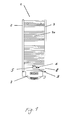
Fig. 1 einen Rohrheizkörper. - In der
Fig. 1 ist ein Rohrheizkörper 1 mit senkrechten Sammelrohren 2, 3, welche durch mit den Sammelrohren 2, 3 verbundene horizontale Heizrohre 4n voneinander beabstandet sind, dargestellt. Im Bereich der unteren Heizrohre 4n sind eine mittige Anschlussverschraubung 5 für den Vor- und Rücklauf eines Heizmediums, ein Thermostatventil 6 sowie eine Lüfterbaugruppe 7 vorgesehen. Im Bereich des unteren Endes des Sammelrohres 3 ist ein Elektroheizstab 8 eingesetzt. Die Sammelrohrenden sind unterhalb der mittigen Anschlussverschraubung 5 im Einsatz- bzw. Einschraubbereich des Elektroheizstabes 8 durch eine Bypassleitung 9 miteinander verbunden.
Vorteilhaft wird durch die Bypassleitung eine optimale Zirkulation des Heizmediums beim Betrieb des Heizkörpers mit Elektroheizstab erreicht.
Claims (1)
- Heizkörper, insbesondere Rohrheizkörper, mit senkrechten Sammelrohren (2, 3), welche durch mit den Sammelrohren verbundene horizontale Heizrohre (4n) voneinander beabstandet sind, wobei im Bereich der unteren Heizrohre (4n) eine mittige Anschlussverschraubung (5) für den Vor- und Rücklauf eines Heizmediums, ein Thermostatventil (6) sowie eine Lüfterbaugruppe (7) vorgesehen sind und im Bereich des unteren Endes eines Sammelrohres ein Elektroheizstab (8) angeordnet ist, dadurch gekennzeichnet, dass die Sammelrohrenden unterhalb der mittigen Anschlussverschraubung (5) im Einsatz- bzw. Einschraubbereich des Elektroheizstabes (8) durch eine Bypassleitung (9) miteinander verbunden sind.
Applications Claiming Priority (1)
| Application Number | Priority Date | Filing Date | Title |
|---|---|---|---|
| DE202010012695U DE202010012695U1 (de) | 2010-09-17 | 2010-09-17 | Heizkörper mit Lüfterbaugruppe und Elektroheizstab |
Publications (1)
| Publication Number | Publication Date |
|---|---|
| EP2431682A2 true EP2431682A2 (de) | 2012-03-21 |
Family
ID=43308170
Family Applications (1)
| Application Number | Title | Priority Date | Filing Date |
|---|---|---|---|
| EP11179879A Withdrawn EP2431682A2 (de) | 2010-09-17 | 2011-09-02 | Heizkörper mit Lüfterbaugruppe und Elektroheizstab |
Country Status (2)
| Country | Link |
|---|---|
| EP (1) | EP2431682A2 (de) |
| DE (1) | DE202010012695U1 (de) |
Families Citing this family (3)
| Publication number | Priority date | Publication date | Assignee | Title |
|---|---|---|---|---|
| ITMI20140107U1 (it) * | 2014-03-19 | 2015-09-19 | Deltacalor S R L | Unita' di riscaldamento con radiatore e termoconvettore |
| EP3067638A1 (de) * | 2015-03-10 | 2016-09-14 | Deltacalor S.r.L. | Handtuchwärmer vom hydraulischen oder elektrohydraulischen typ mit differenzierten heizbereichen |
| IT201600109456A1 (it) * | 2016-10-28 | 2018-04-28 | Ideal Clima Srl | Dispositivo di controllo per un calorifero, calorifero di tipo elettro-idraulico comprendente tale dispositivo di controllo, metodo di controllo di detto calorifero. |
-
2010
- 2010-09-17 DE DE202010012695U patent/DE202010012695U1/de not_active Expired - Lifetime
-
2011
- 2011-09-02 EP EP11179879A patent/EP2431682A2/de not_active Withdrawn
Non-Patent Citations (1)
| Title |
|---|
| None |
Also Published As
| Publication number | Publication date |
|---|---|
| DE202010012695U1 (de) | 2010-12-09 |
Similar Documents
| Publication | Publication Date | Title |
|---|---|---|
| EP2208002B1 (de) | Anordnung zum beheizen von gebäuden mit einer infrarot-heizung | |
| DE202009006988U1 (de) | Warmwasserversorgungsanlage mit einem Warmwasserspeicher | |
| DE102014207540A1 (de) | Heizgerät mit Wärmepumpe | |
| DE102014116519A1 (de) | Hybridheizer für ein Fahrzeug | |
| EP2431682A2 (de) | Heizkörper mit Lüfterbaugruppe und Elektroheizstab | |
| EP3594575A1 (de) | Verfahren zum betreiben eines heizungssystems und heizungssystem | |
| DE10065216A1 (de) | Regeleinrichtung eines zentralen Lüftungsgeräts und Wasserspeicher, insbesondere Brauchwasserspeicher | |
| EP2000742A3 (de) | Mischeinrichtung zur Einstellung der Warmwassertemperatur | |
| EP2031311A3 (de) | Heizungs- und /oder Warmwasserbereitungssystem | |
| DE102006007777B3 (de) | Kombiniertes Heizungs-/Warmwassersystem für ein Fahrzeug | |
| DE202008010401U1 (de) | Solar-Heizungssystem | |
| DE19517250A1 (de) | Gasheizgerät | |
| DE202004009559U1 (de) | Wärmetauscher | |
| EP3120095B1 (de) | Plattenwärmetauscher insbesondere für ein brennstoffbefeuertes heizgerät | |
| DE102006023627B4 (de) | Solaranlage | |
| DE10019302A1 (de) | Wärmepumpe zur Heizungs- und Brauchwassererwärmung | |
| DE102010018086A1 (de) | Wärmeübertragungseinrichtung | |
| DE10360580B4 (de) | Wärmerückgewinnungsgerät mit Solarwärmetauscher | |
| DE202004016209U1 (de) | Wärmetauscher | |
| DE102007002878B3 (de) | Heizanordnung für Gebäude | |
| DE102009044566A1 (de) | Vorrichtung zum Temperieren eines in einem Heizkreislauf umgewälzten Wärmeübertragungsmediums | |
| DE102012011980A1 (de) | Abgasadapter für ein Heizgerät mit Rekuperator | |
| DE102005018050A1 (de) | Luftwärmetauscher | |
| DE102015203293A1 (de) | Gebäude | |
| AT512927B1 (de) | Abgasadapter für ein Heizgerät mit Rekuperator |
Legal Events
| Date | Code | Title | Description |
|---|---|---|---|
| PUAI | Public reference made under article 153(3) epc to a published international application that has entered the european phase |
Free format text: ORIGINAL CODE: 0009012 |
|
| AK | Designated contracting states |
Kind code of ref document: A2 Designated state(s): AL AT BE BG CH CY CZ DE DK EE ES FI FR GB GR HR HU IE IS IT LI LT LU LV MC MK MT NL NO PL PT RO RS SE SI SK SM TR |
|
| AX | Request for extension of the european patent |
Extension state: BA ME |
|
| STAA | Information on the status of an ep patent application or granted ep patent |
Free format text: STATUS: THE APPLICATION IS DEEMED TO BE WITHDRAWN |
|
| 18D | Application deemed to be withdrawn |
Effective date: 20160401 |