EP2674479B2 - Einwegbioreaktor und Kopfplatte sowie Herstellungsverfahren - Google Patents
Einwegbioreaktor und Kopfplatte sowie Herstellungsverfahren Download PDFInfo
- Publication number
- EP2674479B2 EP2674479B2 EP12172304.3A EP12172304A EP2674479B2 EP 2674479 B2 EP2674479 B2 EP 2674479B2 EP 12172304 A EP12172304 A EP 12172304A EP 2674479 B2 EP2674479 B2 EP 2674479B2
- Authority
- EP
- European Patent Office
- Prior art keywords
- head plate
- section
- magnetic
- bioreactor
- connections
- Prior art date
- Legal status (The legal status is an assumption and is not a legal conclusion. Google has not performed a legal analysis and makes no representation as to the accuracy of the status listed.)
- Active
Links
Images


Classifications
-
- C—CHEMISTRY; METALLURGY
- C12—BIOCHEMISTRY; BEER; SPIRITS; WINE; VINEGAR; MICROBIOLOGY; ENZYMOLOGY; MUTATION OR GENETIC ENGINEERING
- C12M—APPARATUS FOR ENZYMOLOGY OR MICROBIOLOGY; APPARATUS FOR CULTURING MICROORGANISMS FOR PRODUCING BIOMASS, FOR GROWING CELLS OR FOR OBTAINING FERMENTATION OR METABOLIC PRODUCTS, i.e. BIOREACTORS OR FERMENTERS
- C12M23/00—Constructional details, e.g. recesses, hinges
- C12M23/28—Constructional details, e.g. recesses, hinges disposable or single use
-
- C—CHEMISTRY; METALLURGY
- C12—BIOCHEMISTRY; BEER; SPIRITS; WINE; VINEGAR; MICROBIOLOGY; ENZYMOLOGY; MUTATION OR GENETIC ENGINEERING
- C12M—APPARATUS FOR ENZYMOLOGY OR MICROBIOLOGY; APPARATUS FOR CULTURING MICROORGANISMS FOR PRODUCING BIOMASS, FOR GROWING CELLS OR FOR OBTAINING FERMENTATION OR METABOLIC PRODUCTS, i.e. BIOREACTORS OR FERMENTERS
- C12M23/00—Constructional details, e.g. recesses, hinges
- C12M23/40—Manifolds; Distribution pieces
-
- C—CHEMISTRY; METALLURGY
- C12—BIOCHEMISTRY; BEER; SPIRITS; WINE; VINEGAR; MICROBIOLOGY; ENZYMOLOGY; MUTATION OR GENETIC ENGINEERING
- C12M—APPARATUS FOR ENZYMOLOGY OR MICROBIOLOGY; APPARATUS FOR CULTURING MICROORGANISMS FOR PRODUCING BIOMASS, FOR GROWING CELLS OR FOR OBTAINING FERMENTATION OR METABOLIC PRODUCTS, i.e. BIOREACTORS OR FERMENTERS
- C12M23/00—Constructional details, e.g. recesses, hinges
- C12M23/42—Integrated assemblies, e.g. cassettes or cartridges
-
- C—CHEMISTRY; METALLURGY
- C12—BIOCHEMISTRY; BEER; SPIRITS; WINE; VINEGAR; MICROBIOLOGY; ENZYMOLOGY; MUTATION OR GENETIC ENGINEERING
- C12M—APPARATUS FOR ENZYMOLOGY OR MICROBIOLOGY; APPARATUS FOR CULTURING MICROORGANISMS FOR PRODUCING BIOMASS, FOR GROWING CELLS OR FOR OBTAINING FERMENTATION OR METABOLIC PRODUCTS, i.e. BIOREACTORS OR FERMENTERS
- C12M27/00—Means for mixing, agitating or circulating fluids in the vessel
- C12M27/02—Stirrer or mobile mixing elements
-
- Y—GENERAL TAGGING OF NEW TECHNOLOGICAL DEVELOPMENTS; GENERAL TAGGING OF CROSS-SECTIONAL TECHNOLOGIES SPANNING OVER SEVERAL SECTIONS OF THE IPC; TECHNICAL SUBJECTS COVERED BY FORMER USPC CROSS-REFERENCE ART COLLECTIONS [XRACs] AND DIGESTS
- Y10—TECHNICAL SUBJECTS COVERED BY FORMER USPC
- Y10T—TECHNICAL SUBJECTS COVERED BY FORMER US CLASSIFICATION
- Y10T156/00—Adhesive bonding and miscellaneous chemical manufacture
- Y10T156/10—Methods of surface bonding and/or assembly therefor
-
- Y—GENERAL TAGGING OF NEW TECHNOLOGICAL DEVELOPMENTS; GENERAL TAGGING OF CROSS-SECTIONAL TECHNOLOGIES SPANNING OVER SEVERAL SECTIONS OF THE IPC; TECHNICAL SUBJECTS COVERED BY FORMER USPC CROSS-REFERENCE ART COLLECTIONS [XRACs] AND DIGESTS
- Y10—TECHNICAL SUBJECTS COVERED BY FORMER USPC
- Y10T—TECHNICAL SUBJECTS COVERED BY FORMER US CLASSIFICATION
- Y10T29/00—Metal working
- Y10T29/49—Method of mechanical manufacture
- Y10T29/49826—Assembling or joining
Definitions
- the invention relates to a head plate for a disposable bioreactor, in particular for use in a, preferably parallel, bioreactor system, for application in cell culture and/or microbiology.
- the invention further relates to a method for producing a head plate for a disposable bioreactor, in particular for use in a, preferably parallel, bioreactor system, for use in cell culture and/or microbiology.
- Bioreactors often also referred to as fermenters, enclose a reaction chamber in which biological or biotechnological processes can be carried out on a laboratory scale. Such processes include, for example, the cultivation of cells, microorganisms, or small plants under defined, preferably optimized, controlled, and reproducible conditions. Bioreactors usually have several connections through which primary and secondary materials as well as various instruments, such as sensors, can be introduced into the reaction chamber, or through which fluid lines, particularly gas lines such as fumigation or exhaust lines, can be connected.
- Bioreactors also usually have an agitator whose agitator shaft can be rotated by a drive, whereby a stirring element that is torsionally rigidly connected to the agitator shaft is also rotated, thus causing the substances present in the reaction chamber to be thoroughly mixed.
- Two or more stirring elements can also be arranged on the agitator shaft and connected to it.
- the stirring element(s) can also be formed integrally with the agitator shaft.
- bioreactors for both cell cultivation and microbiological applications, the use of bioreactors in, preferably parallel, bioreactor systems is preferred.
- Parallel bioreactor systems are used, for example, in DE 10 2011 054 363.5 or the DE 10 2011 054 365.1 described.
- multiple bioreactors can be operated in parallel and controlled with high precision. Even with small working volumes in the individual bioreactors, high-throughput experiments can be conducted that are highly reproducible and scalable.
- the laboratory scale of bioreactors to which the invention relates is approximately up to 2000 ml, for example, with a total reaction volume of approximately 350 ml and a working volume of approximately 60 to approximately 250 ml.
- cell culture refers specifically to the cultivation of animal or plant cells in a nutrient medium outside the organism.
- Bioreactors in laboratory use are often made of glass and/or metal, especially stainless steel, because the bioreactors must be sterilized between different uses, which is preferably achieved by hot steam sterilization in an autoclave.
- the sterilization and cleaning of reusable bioreactors is complex: The sterilization and cleaning process may be subject to validation, and its implementation must be precisely documented for each individual bioreactor. Residues in an incompletely sterilized bioreactor can falsify the results of a subsequent process or render them unusable, as well as disrupt subsequent processes. Furthermore, individual components or materials of the bioreactors can be stressed and sometimes damaged by the sterilization process.
- An alternative to reusable bioreactors are single-use bioreactors, which are used for only one biological or biotechnological process and then disposed of.
- single-use bioreactor for each process, the risk of (cross-)contamination can be reduced and, at the same time, the effort required to carry out and document the proper cleaning and sterilization of a previously used bioreactor is eliminated.
- Single-use bioreactors are often designed as flexible containers, for example, as bags or as containers with at least partially flexible walls.
- bioreactors examples include US 2011/0003374 A1 , US2011/0058447A1 , DE 20 2007 005 868U1 , US 2011/0058448A1 , US2011/0207218A1 , WO 2008/088379A2 , US 2012/0003733 A1 , WO2011/079180A1 , US2007/0253288A1 , US 2009/0275121A1 and US 2010/0028990A1 described.
- a bioreactor is described with flexible walls and with a reactor interior defined by a side wall, a bottom part and a ceiling part, in which at least one mixer is arranged, which can be driven by a drive arranged outside the reactor interior.
- WO 2008/088379 A2 describes environmental containment systems, and in certain embodiments, systems and methods comprising containers or other devices equipped to contain the environment, wherein the containers or devices may be configured to handle fluids and/or perform chemical, biochemical, and/or biological processes.
- these disposable, flexible-walled reactors have, among other disadvantages, the inability to use them in parallel bioreactor systems designed for rigid, reusable bioreactors.
- Dimensionally stable disposable reactors are, for example, EP 2 251 407 A1 and the US 2009/0311776 A1 known.
- the EP 2 251 407 A1 discloses a disposable bioreactor consisting of a container and a lid, whereby the lid is connectable to the container and cannot be removed without damage.
- Examples of dimensionally stable disposable bioreactors available on the market include Celligen Blu, Millipore Mobius, and Sartorius UniVessel.
- these well-known dimensionally stable disposable bioreactors are, on the one hand, expensive, and, on the other hand, their design is tailored to pharmaceutical process development and pharmaceutical production processes. They are used primarily for cell culture processes and are therefore also specifically designed and tailored to such cell culture processes.
- a further object of the invention is to provide a head plate that is cost-effective to manufacture and to specify simple and cost-effective manufacturing methods for a head plate.
- a head plate according to claim 1 and a method for producing a head plate according to claim 11.
- the head plate is particularly suitable for a disposable bioreactor described below, its various aspects and developments.
- a disposable bioreactor of the type mentioned above is characterized in that the agitator and the bearing are arranged entirely within the reaction chamber, and the agitator shaft has a magnetic section arranged and configured such that it can be magnetically coupled in an axial direction to a rotary drive. Since the rotary drive drives the agitator with a stirrer shaft and a stirring element, it is also referred to as a stirring drive.
- this disposable bioreactor can be set in rotation by a magnetic drive.
- One advantage of this design is that both the agitator and the bearing are located entirely within the reaction chamber, meaning that no agitator shaft needs to pass through the head plate. This also eliminates the need to seal such a pass-through of the agitator shaft through the head plate. This has the advantage that the sterility of the reaction chamber cannot be compromised by inadequate sealing of a pass-through in the head plate.
- a further advantage is that the frictional resistance that occurs in designs with sealed pass-throughs, which can lead to, among other things, damage to septum components, is completely avoided.
- a coupling between a magnetic section of the stirrer shaft and a drive arranged outside the reaction chamber on the outside of the head plate is effected via a magnetic coupling in the axial direction, i.e. in the direction of the rotation axis or parallel thereto.
- a minimal air gap is preferably formed between a magnetic section of the stirrer shaft and a magnetic drive section of the rotary drive.
- Such a frontal magnetic coupling between the stirrer shaft and the rotary drive has, compared to a coupling in the radial direction, in which a magnetic section of the rotary drive is arranged on the outside circumference around a magnetic section on the stirrer shaft and, for example, in the US 2011/0058447 A1
- the advantage of the rotary drive is that only a small amount of space is required on the head plate.
- a rotary drive with a front-side magnetic coupling can, for example, be essentially cylindrical.
- the cross-sectional area of the cylinder can essentially correspond to the area required for the frontal magnetic coupling. This leaves more space on the head plate for additional connections for instruments, sensors, or functional elements.
- the head plate can, for example, have a bulge, which can, for example, have a circular cross-section and which, for example, a rotary drive arranged outside the reaction chamber can engage with a ring in order to arrange the rotary drive concentrically above the bulge and the magnetic section of the stirrer shaft, which is preferably also arranged concentrically therein.
- the magnetic section of the stirrer shaft is preferably arranged at one end of the stirrer shaft and preferably has a larger diameter or a larger circumference than the remaining section of the stirrer shaft.
- the magnetic section is formed integrally with the stirrer shaft. This has the advantage of reducing the number of parts in the reaction chamber and thus also reducing possible gaps and dead spaces between different parts.
- the magnetic section consists of a composite material with a plastic matrix and a magnetic material or comprises such a composite material.
- USP United States Pharmacopeia
- the magnetic section is produced by spraying the two-component material with a magnetic component onto the agitator shaft.
- the magnetic section has a cross-section in a plane orthogonal to the agitator shaft and has a magnetic force effect over the majority of this cross-section, preferably over the entire cross-section, for a magnetic coupling in the axial direction with a rotary drive.
- Such a configuration of a preferably flat, continuous cross-section of the region with magnetic force can be achieved in particular by injection molding a composite material with a plastic matrix and a magnetic material in an injection mold, which in turn has a magnet to align the magnetic material of the composite material during injection molding.
- the cross-section of the magnetic section with magnetic force is preferably circular, elliptical, or rectangular.
- segments of different polarity are preferably formed. For example, the segments can form a star-shaped pattern or a pattern with pie-shaped segments.
- Such a design has several advantages: Firstly, a higher torque can be transmitted compared to a design with several bar magnets arranged in a ring, which is particularly necessary to achieve high speeds of over 1500 rpm, in particular up to 2000 rpm, up to 3000 rpm or more, which are particularly required for applications in microbiology. At the same time, the required cross-sectional area at the end of the stirrer shaft and thus the required installation space on the head plate can be kept small. Furthermore, the design of certain pole segment patterns can achieve a specific fit between bioreactors and a correspondingly designed rotary drive, thus increasing process reliability, since only bioreactors with suitable pole segmentation can be driven by a rotary drive.
- the magnetic section can also be integrally connected to the agitator shaft, preferably to one end, for example by spraying the composite material onto the agitator shaft.
- the magnetic section can be formed as a separate part, preferably by injection molding, and arranged on the agitator shaft.
- a disposable bioreactor as mentioned above or a disposable bioreactor according to the first aspect is characterized in that the bearing is designed as a rolling bearing.
- the sliding bearings used in known dimensionally stable disposable bioreactors for use in cell culture have the disadvantage that the speed of the agitator is limited to ranges of about 500 rpm, since higher speeds generate waste heat due to strong friction of the shaft and the bearing, which can lead to melting of the bearing and thus to a standstill of the shaft, which can disrupt the cultivation process.
- a plain bearing has the further disadvantage of increased material, especially plastic, abrasion, which would represent an undesirable agglomeration nucleus for cells in the reaction chamber and therefore must be captured, for example, in a bearing housing.
- the bearing of the stirrer shaft as a rolling bearing, significantly higher speeds of over 1500 rpm, in particular up to 2000 rpm, up to 3000 rpm or more, can be achieved, which are particularly required for applications in microbiology.
- the rolling bearing be designed as a polymer ball bearing with glass balls, wherein the polymer ball bearing preferably has a cage made of a thermoplastic material, for example, polyethylene, polypropylene, polyvinylidene fluoride, polyetheretherketone, or polytetrafluoroethylene.
- a thermoplastic material for example, polyethylene, polypropylene, polyvinylidene fluoride, polyetheretherketone, or polytetrafluoroethylene.
- the disposable bioreactor mentioned at the outset or one of the previously described disposable bioreactors according to the first or second aspect is characterized in that the head plate and the container are non-detachably connected to one another, the head plate is made of a first material and the container is made of a second material and the stirring shaft and/or the stirring element is/are made of a third material, wherein the first material and the second material have a higher temperature resistance than the third material.
- the head plate and the vessel are permanently connected to each other, for example, by a material-to-material joining process such as welding.
- Ultrasonic welding is particularly preferred, as this method offers high process reliability and results in a very good seal between the head plate and the reaction chamber, thus effectively sealing the reaction chamber from the environment. Ultrasonic welding is also a very fast joining process and reduces manufacturing costs.
- a permanent connection between the head plate and the container has the advantage that after sterilization during the manufacturing process, the disposable bioreactor cannot be opened again, thus reducing the risk of contamination of the reaction chamber before use. Furthermore, this permanent connection has the advantage that the disposable bioreactor cannot be opened even after use and retains its closed, dimensionally stable design.
- Disposable bioreactors made of materials with lower temperature resistance have the disadvantage that they are damaged during decontamination or post-process sterilization, e.g., they partially melt, and therefore must be sterilized in outer packaging, preferably with temperature resistance.
- Constructing the head plate and container from materials with a temperature resistance that allows decontamination, i.e., materials that are not destroyed or significantly damaged during decontamination has the advantage that the disposable bioreactor can be decontaminated, for example, by steam sterilization, without the need for additional packaging or placing it in another container, since the head plate and container can withstand this decontamination process.
- the combination with a stirrer shaft and/or a stirring element made of a material with lower temperature resistance achieves the advantage that the stirrer shaft and/or the stirring element are destroyed or at least rendered inoperable during the decontamination process.
- the third material has corresponding properties for this purpose. In particular, a temperature resistance of the third material that does not withstand a decontamination process is preferred.
- the first material of the head plate and the second material of the container are the same, which is particularly advantageous if ultrasonic welding is used as the joining method for connecting the head plate and the container.
- the temperature resistance of materials is preferably defined here as their glass transition temperature.
- the first material and the second material have a higher glass transition temperature than the third material.
- the glass transition temperature (Tg) is a specific material property of plastics. It describes the temperature at which amorphous or semi-crystalline polymers transition from the solid state to the liquid state, resulting in a significant change in physical parameters, such as hardness and elasticity.
- the first material and the second material have a glass transition temperature of at least 121°C and preferably the third material has a glass transition temperature of below 121°C. It is furthermore particularly preferred that the third material has a glass transition temperature of above 50°C, in particular above 55°C, above 60°C, above 65°C, above 70°C, above 75°C or above 80°C. It is furthermore preferred that the first and the second material have a glass transition temperature of above 125°C, in particular above 130°C, above 140°C, above 150°C, above 160°C, above 170°C or above 180°C.
- the glass transition temperatures of the first material and the second material are preferably at least 5°C higher, in particular at least 10°C higher, at least 15°C higher, at least 20°C higher, at least 25°C higher, at least 30°C higher, at least 25°C higher, at least 30°C higher, at least 40°C higher, at least 50°C higher, at least 60°C higher, at least 70°C higher or at least 80°C higher than the glass transition temperature of the third material.
- a particularly preferred material pairing results from the construction of the head plate and the container from polyamide, polycarbonate, polymethylpentene or polypropylene and the construction of the stirring element and/or the stirring shaft from polystyrene. These materials have properties that make them suitable for use in both cell culture and microbiology.
- the materials mentioned for the head plate and container differ from the material mentioned for the stirring element and/or the stirring shaft in their temperature resistance such that the polyamide, polycarbonate, polymethylpentene or polypropylene survives a decontamination process, in particular by steam sterilization, essentially unscathed, whereas the polystyrene is melted during steam sterilization, meaning that the stirring shaft or stirring element cannot be reused.
- a preferred embodiment provides for the head plate and the container to be glued together.
- ultrasonic welding is particularly preferred as a manufacturing method because it combines high process reliability and the associated reliable connection of the head plate and container with fast and simple production with reduced manufacturing effort.
- the head plate is constructed in one piece. This reduces the number of parts in the reaction chamber, thus avoiding dead spaces and gaps, and also eliminates additional work steps during assembly or installation of the disposable bioreactor. Manufacturing the head plate using the injection molding process is particularly preferred.
- the head plate is preferably made of polyamide, polycarbonate, polymethylpentene, or polypropylene. These materials have the advantage of meeting the requirements for use in both cell culture and microbiology applications, while also demonstrating high temperature resistance.
- a further preferred embodiment of the disposable bioreactor provides that the head plate has a plurality of immersion tubes on its inside that protrude into the reaction chamber.
- These immersion tubes are preferably designed as hollow sleeves and can accommodate various instruments, sensors, or lines, in particular flexible hoses.
- the immersion tubes are preferably designed as dimensionally stable tubes.
- the immersion tubes on the inside of the head plate preferably correspond to connections on the outside of the head plate, so that media or elements can be introduced into or removed from the reaction chamber through the connections and the immersion tubes.
- the immersion tubes, or at least some of the immersion tubes preferably protrude far enough into the reaction chamber that, when the disposable bioreactor is used as intended, they are immersed in a content located in the reaction chamber, for example a liquid.
- immersion tubes preferably protrude far enough into the reaction chamber that, when the disposable bioreactor is used as intended, they are immersed in a content located in the reaction chamber, for example a liquid.
- a preferred embodiment of the disposable bioreactor is one in which the head plate has a recess for receiving the bearing.
- Such an outwardly directed recess of the head plate is preferred in order to accommodate the bearing of the agitator shaft arranged in the reaction chamber and thus to reduce the usable reaction chamber as little as possible by the arrangement of the bearing.
- a rotary drive for the agitator can be arranged on such a recess on the outside of the head plate.
- the recess has no opening in the head plate, which is particularly advantageous in the case of a magnetic coupling, in particular the previously described frontal magnetic coupling. between the rotary drive and the agitator shaft is preferred.
- the bioreactor has a head plate described below or one of its further developments.
- a head plate described below or one of its further developments.
- the disposable bioreactor has a bearing housing that defines a bearing space for accommodating the bearing within the reaction space.
- the embodiment described here has the advantage that the bearing space is partially, preferably predominantly, arranged in the region of the bulge in the head plate, thus leaving a portion of the reaction space located below the head plate essentially available for the intended use of the bioreactor.
- the bearing housing defines the bearing space from the reaction space, for example, by means of a plain bearing bush.
- the bearing housing is preferably detachably attached to the inside of the head plate or permanently connected to the inside of the head plate.
- a detachable attachment of the bearing housing can be, for example, a snap-in connection, clip connection, or screw connection.
- a permanent connection of the bearing housing to the inside of the head plate can be achieved, for example, by gluing or welding, in particular ultrasonic welding.
- a biotechnological device comprising a previously described disposable bioreactor according to its various aspects or developments, and a rotary drive with a magnetic drive section which is arranged and designed such that it can be magnetically coupled in an axial direction to the magnetic section of the stirrer shaft.
- the magnetic drive section consists of a composite material with a plastic matrix and a magnetic material or comprises such a composite material.
- the composite or two-component material with a magnetic component is sprayed onto a front-side drive element of the rotary drive.
- the magnetic drive section has a cross-section in a plane orthogonal to a rotation axis, and has a magnetic force effect over the majority of this cross-section, preferably over the entire cross-section, for a magnetic coupling in the axial direction with the magnetic section of the agitator shaft.
- Such a configuration of a preferably flat, continuous cross-section of the region with magnetic force effect of the drive section can be achieved in particular by injection molding a composite material with a plastic matrix and a magnetic material in an injection mold, which in turn has a magnet to align the magnetic material of the composite material during injection molding.
- the cross-section of the magnetic drive section with magnetic force effect is preferably circular, elliptical, or rectangular.
- segments of different polarity are preferably formed.
- the segments can form a star-shaped pattern or a pattern with pie-shaped segments.
- the pattern of the segments of the magnetic drive section is preferably coordinated with the pattern of the segments of the magnetic section of the agitator shaft.
- Such a design has several advantages: Firstly, a higher torque can be transmitted compared to a design with several bar magnets arranged in a ring, which is particularly necessary to achieve high speeds of over 1500 rpm, in particular up to 2000 rpm, up to 3000 rpm or more, which are particularly required for applications in microbiology. At the same time, the required cross-sectional area of the rotary drive and thus the required installation space on the head plate can be kept small. Furthermore, the design of certain pole segment patterns can achieve a specific fit between bioreactors and a correspondingly designed rotary drive, thus increasing process reliability, since only bioreactors with suitable pole segmentation can be driven by a rotary drive.
- the above-mentioned object is achieved by a head plate according to claim 1.
- This head plate is particularly suitable for a previously described disposable bioreactor, its various aspects and developments.
- the head plate comprises an inner side and an outer side opposite the inner side, wherein the inner side has a plurality of immersion tubes and the outer side has a plurality of connections, and wherein the head plate is made in one piece.
- Such a one-piece head plate design which simultaneously features multiple connections on its exterior and multiple dip tubes on its interior, offers the advantage of a particularly high degree of integration. This significantly simplifies the assembly of a disposable bioreactor, as the dip tubes replace lines, such as hoses, which, in conventional head plates, must be attached to existing connections on the interior.
- the one-piece design also reduces the number of parts in the reaction chamber and thus the number of gaps and dead spaces.
- the immersion tubes have a length such that, at a minimum fill volume of a disposable bioreactor with which the head plate is used, the immersion tubes are immersed in the contents or culture broth.
- a length of the immersion tubes of at least 85 percent of the diameter of the head plate is preferred.
- a diameter here is understood, for example, to be the diameter of a head plate with a circular cross-section.
- the diameter is understood to be the extension of the head plate in one of its two main directions of extension.
- the dip tubes have a length of more than 50 percent of the diameter of the head plate. Particularly preferred is a length of the dip tubes of at least 75 percent, at least 80 percent, at least 85 percent, at least 90 percent, or at least 95 percent of the diameter of the head plate. Furthermore, it is preferred that the length of the dip tubes corresponds at least to the diameter of the head plate. Furthermore, a length of the dip tubes that is greater than 1.1 times, greater than 1.2 times, greater than 1.3 times, greater than 1.4 times, greater than 1.5 times, greater than 1.6 times, greater than 1.7 times, greater than 1.8 times, greater than 1.9 times, or greater than twice the diameter of the head plate is preferred.
- the head plate preferably has at least three, in particular at least five immersion tubes.
- the dip tubes preferably have an inner diameter of less than 8 millimeters, in particular less than less than 7 millimeters, less than 6 millimeters, less than 5 millimeters, less than 4.8 millimeters, less than 4.75 millimeters, less than 4.7 millimeters, less than 4.5 millimeters, less than 4.3 millimeters, less than 4 millimeters, less than 3.5 millimeters, less than 3 millimeters, less than 2.5 millimeters, less than 2 millimeters, less than 1.5 millimeters or less than 1 millimeter.
- At least two, preferably several, of the dip tubes of a head plate have different inner diameters. It is further preferred that at least two, preferably several, of the dip tubes of a head plate have different lengths. These configurations are preferred to adapt the dip tubes to different uses, thus creating a flexible, broad range of applications for a disposable bioreactor with such a head plate.
- the head plate is manufactured by injection molding.
- the head plate is preferably made of polyamide, polycarbonate, polymethylpentene, or polypropylene. These materials have the advantage of meeting the requirements for use in both cell culture and microbiology applications while also demonstrating high temperature resistance.
- the head plate preferably has a recess for accommodating a bearing of an agitator. This is particularly preferred if the head plate is to be used as the head plate of a previously described disposable bioreactor with a magnetic coupling between the agitator and the rotary drive.
- the diameter of at least one of the dip tubes tapers at its end facing away from the head plate.
- this tapered dip tube and/or one or more of the other dip tubes are closed at their end facing away from the head plate and are further preferably provided with an opening at this closed end, wherein this opening preferably has a diameter that is smaller than the inner diameter of the dip tube. This is particularly preferred if such a dip tube is to be used as a gassing tube.
- the immersion tubes preferably have a wall thickness of less than 3 millimeters, in particular a wall thickness of less than 2 millimeters, less than 1.5 millimeters or less than 1 millimeter.
- At least one, preferably two, of the connections on the outside of the head plate have a thread, preferably an internal thread. This allows screw connections to be made at the connections without first having to attach additional connection elements to the head plate.
- the object mentioned at the outset is achieved by a method for producing a head plate for a disposable bioreactor according to claim 12.
- FIG. 1A , B , C , D , E and 2A , B , C , D , E , F is a disposable bioreactor 1 or a biotechnological device with a disposable bioreactor, a connection device and a temperature control device for use in a Fig. 3
- the parallel bioreactor system 10 shown in FIG. 1 for use in cell culture and/or microbiology is shown.
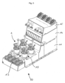
- Fig. 3 The parallel bioreactor system 10 shown has a base block 11 with four receptacles 12 arranged therein, into each of which a bioreactor 1 can be detachably inserted.
- a temperature controller is preferably arranged in the base block 11, which is designed to heat or cool the disposable bioreactors 1 arranged in the receptacles 12 as required.
- An arrangement with containers 13 is formed adjacent to the base block 11.
- the base block 11 has a stacking surface on which two functional blocks 14, 15 are removably arranged in a stack formation and are designed, for example, as a storage and display station or pump station, for example, to supply or discharge the fluids required for the operation of the bioreactors.
- Such a parallel bioreactor system 10 has the advantage of a small footprint and high scalability, since several of these parallel bioreactor systems 10, each with four disposable bioreactors 1, can be arranged side by side.
- the disposable bioreactors 1 have the advantage of being able to be used as reusable bioreactors in such a parallel bioreactor system for application in cell culture and/or microbiology.
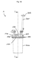
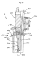
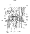
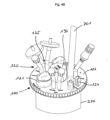
- the disposable bioreactor 1 comprises a head plate 100, a dimensionally stable container 200, and an agitator 300.
- the head plate 100 and the container 200 enclose a reaction chamber 400.
- the head plate 100 has an inner side 101 facing the reaction chamber, on which several immersion tubes 110 are arranged, which extend into the reaction chamber 400.
- Several connections 120 are arranged on an outer side 102 of the head plate 100 facing away from the reaction chamber 400.
- the agitator 300 has an agitator shaft 310 with a rotational axis and a stirring element 320.
- the stirring element 320 is designed here with blades inclined at 45°, for example, as a pitch blade impeller. Alternatively, at least one Rushton impeller can also be used as the stirring element.
- the stirring element 320 is attached to the agitator shaft 310 in a torsionally rigid manner, so that when the agitator shaft 310 rotates, the stirring element 320 also rotates.
- the head plate 100 and the container 200 are preferably made of polyamide and are permanently connected to one another by ultrasonic welding.
- the agitator 300 in particular the tubular shaft 310 and/or the agitator element 320, are preferably made of polystyrene. Polystyrene has a lower temperature resistance than polyamide, so that during steam sterilization of the disposable bioreactor 1, the agitator 300 is rendered unusable and thus reuse of the disposable bioreactor 1 is excluded.
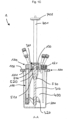
- the agitator shaft 310 is mounted in a bearing 500 for rotation about the rotation axis.
- the bearing 500 is arranged in a recess 130 of the head plate 100.
- a bearing housing 510 defines a bearing space 520 in the reaction chamber 400.
- the agitator shaft 310 extends out of the bearing housing 510 through a plain bearing bushing 530.
- the entire bearing housing can be made of a material suitable for a plain bearing. This has the advantage of reducing the number of individual parts and a high degree of integration, which also has advantageous effects in production and assembly.
- the bearing 500 is designed as a rolling bearing and is preferably a polymer ball bearing 501 with a cage made of polyethylene, polypropylene, polyvinylidene fluoride, polyetheretherketone, or polytetrafluoroethylene, as well as glass balls 502.
- the agitator 300 and the bearing 500 are arranged entirely in the reaction chamber 400.
- the agitator shaft 310 has a magnetic section 311, 311', which can be magnetically coupled in an axial direction to a rotary drive 600.
- the magnetic section 311, 311' of the agitator shaft 310 is magnetically coupled at the end, i.e. in the axial direction, to a rotary drive 600.
- the rotary drive 600 is essentially cylindrical and has a cross-sectional area that essentially corresponds to the cross-sectional area of the bulge 130 on the head plate 100.
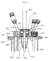
- a drive element 613 drives a magnetic drive section 611, 611'.
- Fig. 1D , E and 2E , F The frontal, axial magnetic coupling shown has the advantage of a particularly small space requirement for the drive on the head plate.
- a magnetic section 311 is arranged at the end of the stirring shaft 310, in which magnets 312 are arranged, preferably in a ring-shaped arrangement.
- the magnetic section 311 with the magnets 312 arranged therein is torsionally rigidly connected to the agitator shaft 310 via a hexagon nut 313.
- Magnets can also be arranged in the magnetic drive section 611 of the rotary drive, the arrangement of which is preferably aligned with the arrangement of the magnets 312 of the magnetic section 311 of the agitator shaft 310.
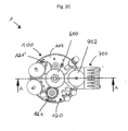
- the magnetic section 311' has a cross-section in a plane orthogonal to the agitator shaft 31, and has a magnetic force effect over the majority of this cross-section, preferably over the entire cross-section, for a magnetic coupling in the axial direction with a rotary drive 600.
- the cross-section of the magnetic section 311' with magnetic force effect is preferably circular here and preferably has segments 315a,b of different polarity, which form, for example, a star-shaped pattern or a pattern with pie-shaped segments.
- the magnetic drive section 611' of the rotary drive 600 also has a cross-section in a plane orthogonal to a rotation axis, and has a magnetic force effect over the majority of this cross-section, preferably over the entire cross-section, for a magnetic coupling in the axial direction with the magnetic section 311' of the stirring shaft 310.
- the cross-section of the magnetic drive section 611' with magnetic force is preferably circular and preferably has segments 615 of different polarity, which form, for example, a star-shaped pattern or a pattern with pie-shaped segments.
- the pattern of the segments 615 of the magnetic drive section 611' is preferably matched to the pattern of the segments 315a,b of the magnetic section 311' of the agitator shaft 310.
- the magnetic section 311' and/or the magnetic drive section 611' is/are preferably formed from a composite or two-component material, in particular a magnet-polymer mixture, and further preferably manufactured by injection molding.
- the magnetic section 311' and/or the magnetic drive section 611' can be formed as separate parts that are arranged on the agitator shaft 310 or the drive element 613 and fastened there, optionally releasably.
- a one-piece design of the magnetic section 311' with the agitator shaft 310 preferably by spraying a composite or two-component material, in particular a magnet-polymer mixture, onto one end of the agitator shaft 310.
- a one-piece design of the magnetic drive section 611' with a drive element 613 preferably by spraying a composite or two-component material, in particular a magnet-polymer mixture, onto the drive element 613.
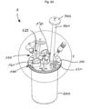
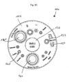
- the head plate 100 shown is preferably formed in one piece and manufactured by injection molding, preferably from polyamide, including the connections 120 arranged on the outside and the immersion tubes 110 arranged on the inside.
- the immersion tubes 110 correspond to some of the connections 120, so that instruments, sensors, lines, such as hoses, can be introduced into or removed from the reaction chamber through the corresponding connections 120 through the immersion tubes 110.
- the connections 120 serve to provide the substances necessary for the reaction process and/or to remove substances from the reaction chamber 400, e.g., gases generated during operation.
- the connections 120 can also be referred to as overlay and the immersion tubes 110 as submersible.
- connection 123 serves, for example, to connect to an exhaust hose 701, at the end of which an exhaust gas sterile filter 702 is arranged.
- a gas stream discharged through the exhaust hose 701 can, for example, be treated by another device, preferably a temperature control device.
- the sterile filter 702 serves to filter the exhaust gas before it exits.
- a connection slot 124 is formed by two U-shaped profiles, which are particularly suitable for accommodating an exhaust gas cooling element 700.
- the exhaust gas cooling element 700 can, in particular, be designed as a temperature control element, as described in the applicant's parallel application of the same date entitled 'Device for a sterile disposable fluid line of a disposable bioreactor and method for treating a fluid stream'.
- Such a cooling element 700 serves to cool the exhaust gas in the hose 701 and to condense liquid entrained therein, which can then be returned, preferably by gravity, to the reaction chamber 400 and thus, on the one hand, is available again in the reaction chamber and, on the other hand, does not clog the sterile filter 702.
- the connections 120 can be designed, for example, as screw connections 121 with an internal thread, as clamp connections 122 or as conical connections 125.
- the Fig. 5A , B , C The illustrated arrangement of connections 120 and immersion tubes 110 allows for high flexibility, so that a disposable reactor with such a head plate 100 is suitable for a variety of applications in both cell culture and microbiology. Unused connections 120 can be closed for the application, as is the case, for example, with the two screw connections 121 in Fig. 1A and 4A , B Furthermore, for example, in Fig. 5A , B , C three conical connections 125 located between the two screw connections 121 can be seen, at which in the Fig. 4A , B Hoses are attached. In the Fig.
- the rear of the two screw connections 121' is closed with a cap, whereas the front of the two screw connections 121 carries a functional element.
- a functional element For example, pH or DO (dissolved oxygen), temperature, or other sensors can be arranged at the connections 120 and preferably introduced into the reaction chamber via the immersion tubes 110.
- the two screw connections 121 are preferably designed as PG 13.5 threads.
- a particularly preferred combination of connections 120 of a head plate 100 includes two screw connections designed as PG 13.5 threads, gas connections for headspace and underwater (or sub-media) gas supply, an exhaust gas connection and a plug connection for exhaust gas cooling, a sampling connection with a sampling valve, for example a swabable valve, a media connection, two immersion tubes, a connection for a resistance temperature detector (T or RTD) and a dissolved oxygen (DO) sensor connection with a permeable membrane.
- a particularly preferred combination of connections 120 on the head plate 100 is shown in the Fig. 5A , B , C shown.
- Tubing and connection materials used with the disposable bioreactor 1 that may come into contact with reaction media are preferably made of materials certified according to the United States Pharmacopeia (USP) Class VI, such as polystyrene, polycarbonate, polyamide, or silicone.
- USP United States Pharmacopeia
- the tubing to be used is preferably flexible tubing made of thermoplastic elastomers.
Landscapes
- Health & Medical Sciences (AREA)
- Organic Chemistry (AREA)
- Wood Science & Technology (AREA)
- Bioinformatics & Cheminformatics (AREA)
- Life Sciences & Earth Sciences (AREA)
- Engineering & Computer Science (AREA)
- Zoology (AREA)
- Chemical & Material Sciences (AREA)
- Microbiology (AREA)
- Sustainable Development (AREA)
- Biotechnology (AREA)
- General Health & Medical Sciences (AREA)
- General Engineering & Computer Science (AREA)
- Biochemistry (AREA)
- Genetics & Genomics (AREA)
- Biomedical Technology (AREA)
- Clinical Laboratory Science (AREA)
- Apparatus Associated With Microorganisms And Enzymes (AREA)
- Mixers With Rotating Receptacles And Mixers With Vibration Mechanisms (AREA)
- Mixers Of The Rotary Stirring Type (AREA)
- Accessories For Mixers (AREA)
Description
- Die Erfindung betrifft eine Kopfplatte für einen Einwegbioreaktor, insbesondere zur Verwendung in einem, vorzugsweise parallelen, Bioreaktorsystem, für die Anwendung in der Zellkultur und/oder der Mikrobiologie.
- Die Erfindung betrifft ferner ein Verfahren zum Herstellen einer Kopfplatte für einen Einwegbioreaktor, insbesondere zur Verwendung in einem, vorzugsweise parallelen, Bioreaktorsystem, für die Anwendung in der Zellkultur und/oder der Mikrobiologie.
- Bioreaktoren, die häufig auch als Fermenter bezeichnet werden, schließen einen Reaktionsraum ein, in dem biologische bzw. biotechnologische Prozesse im Labormaßstab durchgeführt werden können. Zu solchen Prozessen zählt beispielsweise die Kultivierung von Zellen, Mikroorganismen oder kleinen Pflanzen unter definierten, vorzugsweise optimierten, kontrollierten und reproduzierbaren Bedingungen. Bioreaktoren verfügen dazu meist über mehrere Anschlüsse, über die Primär- und Sekundärstoffe sowie verschiedene Instrumente, wie beispielsweise Sensoren, in den Reaktionsraum eingebracht werden können oder über die beispielsweise Fluidleitungen, insbesondere Gasleitungen, wie Begasungs- oder Abgasleitungen, angeschlossen werden können. Bioreaktoren weisen ferner in der Regel ein Rührwerk auf, dessen Rührwelle von einem Antrieb in Rotation versetzt werden kann, wodurch ein drehsteif mit der Rührwelle verbundenes Rührelement ebenfalls in Rotation versetzt wird und so eine Durchmischung der im Reaktionsraum vorhandenen Stoffe bewirkt. Es können auch zwei oder mehr Rührelemente, meist axial beabstandet, auf der Rührwelle angeordnet und mit dieser verbunden sein. Das Rührelement bzw. die Rührelemente kann bzw. können auch einstückig mit der Rührwelle ausgebildet sein.
- Sowohl für den Anwendungsbereich der Zellkultivierung als auch für den mikrobiologischen Anwendungsbereich ist die Verwendung von Bioreaktoren in, vorzugsweise parallelen, Bioreaktorsystemen bevorzugt. Parallele Bioreaktorsysteme sind beispielsweise in der
DE 10 2011 054 363.5 oder derDE 10 2011 054 365.1 beschrieben. In einem solchen Bioreaktor-System können mehrere Bioreaktoren parallel betrieben und mit hoher Genauigkeit kontrolliert werden. Dabei können auch bei kleinen Arbeitsvolumina in den einzelnen Bioreaktoren Experimente mit hohem Durchsatz durchgeführt werden, die gut reproduzierbar und skalierbar sind. Der Labormaßstab von Bioreaktoren, auf die sich die Erfindung bezieht, liegt etwa bei einer Größe von bis zu 2000 ml, beispielsweise bei einem Gesamtvolumen des Reaktionsraums von etwa 350 ml bei einem Arbeitsvolumen von etwa 60 bis etwa 250 ml. - Im Anwendungsbereich der Zellkultur werden solche parallelen Bioreaktorsysteme beispielsweise für auf statistischen Planungsmethoden (Design of Experiments DoE) basierenden Versuchsreihen zur Prozessoptimierung, die Prozessentwicklung sowie die Forschung und Entwicklung eingesetzt, beispielsweise um verschiedene Zelllinien, wie Chinese Hamster Ovary (CHO)-, Hybridoma- oder NSO-Zelllinien, zu kultivieren. Unter dem Begriff "Zellkultur" wird im Rahmen des vorliegenden Textes insbesondere die Kultivierung tierischer oder pflanzlicher Zellen in einem Nährmedium außerhalb des Organismus verstanden.
- Im Anwendungsbereich der Mikrobiologie werden parallele Bioreaktorsysteme ebenfalls für auf statistischen Planungsmethoden (Design of Experiments DoE) basierenden Versuchsreihen zur Prozessoptimierung, die Prozessentwicklung sowie die Forschung und Entwicklung eingesetzt, beispielsweise um verschiedene Mikroorganismen, insbesondere Bakterien oder Pilze, z.B. Hefen, zu kultivieren.
- Aufgrund von meist begrenztem Platz im Labor werden dabei geringe Platzanforderungen, insbesondere geringe Stellplatzanforderungen sowohl für Bioreaktorsysteme als auch für Bioreaktoren selbst angestrebt.
- Bioreaktoren im Laboreinsatz sind oft aus Glas und/oder Metall, insbesondere rostfreiem Stahl, ausgebildet, da die Bioreaktoren zwischen verschiedenen Anwendungen sterilisiert werden müssen, was vorzugsweise durch eine Heißdampfsterilisation in einem Autoklaven erfolgt. Die Sterilisierung und Reinigung wieder verwendbarer Bioreaktoren ist aufwändig: Der Sterilisations- und Reinigungsprozess kann einer Validierung unterliegen und seine Durchführung ist für jeden einzelnen Bioreaktor genau zu dokumentieren. Rückstände in einem nicht vollständig sterilisierten Bioreaktor können die Ergebnisse eines nachfolgenden Prozesses verfälschen oder unbrauchbar machen und einen nachfolgenden Prozessablauf stören. Des Weiteren können einzelne Bestandteile bzw. Materialien der Bioreaktoren durch den Sterilisationsprozess beansprucht und z.T. beschädigt werden.
- Eine Alternative zu wieder verwendbaren Bioreaktoren stellen Einwegbioreaktoren dar, die für die Durchführung lediglich eines biologischen bzw. biotechnologischen Prozesses verwendet und anschließend entsorgt werden. Durch die Bereitstellung eines neuen, vorzugsweise im Herstellungsprozess sterilisierten, Einwegbioreaktors für jeden Prozess kann die Gefahr einer (Kreuz-)Kontamination reduziert werden und gleichzeitig entfällt der Aufwand der Durchführung und Dokumentation einer einwandfreien Reinigung und Sterilisierung eines zuvor genutzten Bioreaktors. Einwegbioreaktoren sind oft als flexible Behälter ausgebildet, beispielsweise als Beutel oder als Behälter mit zumindest abschnittsweise flexiblen Wänden. Beispiele für solche Bioreaktoren sind in
US 2011/0003374 A1 ,US2011/0058447A1 ,DE 20 2007 005 868U1 ,US 2011/0058448A1 ,US2011/0207218A1 ,WO 2008/088379A2 ,US 2012/0003733 A1 ,WO2011/079180A1 ,US2007/0253288A1 ,US 2009/0275121A1 undUS 2010/0028990A1 beschrieben. In derDE 20 2007 005 868 U1 z.B. ist ein Bioreaktor beschrieben mit flexiblen Wänden und mit einem von einer Seitenwandung, einem Bodenteil und einem Deckenteil umgrenzten Reaktorinnenraum, in dem mindestens ein Mischer angeordnet ist, der von einem außerhalb des Reaktorinnenraumes angeordneten Antrieb antreibbar ist. DieWO 2008/088379 A2 beschreibt Umgebungseinschließungssysteme, und in bestimmten Ausführungsformen Systeme und Verfahren, die Behältnisse oder andere Vorrichtungen umfassen, die umgebungseinschließend ausgerüstet sind, wobei die Behältnisse oder Vorrichtungen ausgebildet sein können, Fluide zu handhaben und/oder chemische, biochemische und/oder biologische Prozesse ausführen zu können. Diese Einwegreaktoren mit flexiblen Wänden haben jedoch unter anderem den Nachteil, dass sie in parallelen Bioreaktorsystemen, die für formstabile, wieder verwendbare Bioreaktoren ausgelegt sind, nicht verwendet werden können. - Ferner sind aus Gründen der Übertragbarkeit von Prozessen auf andere Maßstäbe unter anderem auch qualitativ vergleichbare und insbesondere definierte Strömungsverhältnisse (insbesondere bei der Durchmischung) im Kultivierungsraum wichtig. Diese Anforderung kann bei Bioreaktoren mit flexiblen Wänden nicht bzw. nur mit aufwändigen Zusatzmaßnahmen gewährleistet werden.
- Formstabile Einwegreaktoren sind beispielsweise aus der
EP 2 251 407 A1 und derUS 2009/0311776 A1 bekannt. DieEP 2 251 407 A1 offenbart einen Einweg-Bioreaktor, der aus einem Behälter und einem Deckel besteht, wobei der Deckel mit dem Behälter verbindbar ist und nicht zerstörungsfrei entfernt werden kann. Am Markt erhältliche formstabile Einwegbioreaktoren sind beispielsweise Celligen Blu, Millipore Mobius und Sartorius UniVessel. Diese bekannten formstabilen Einwegbioreaktoren sind jedoch einerseits hochpreisig und andererseits von ihrer Konstruktion auf die pharmazeutische Prozessentwicklung und pharmazeutische Produktionsprozesse abgestimmt. Sie werden insbesondere für Zellkulturprozesse verwendet und sind demnach auch insbesondere auf solche Zellkulturprozesse konstruiert und abgestimmt. Für Anwendungen in der Mikrobiologie gelten jedoch andere Anforderungen, sowohl was die am Markt erzielbaren Preise als auch geeignete Konstruktion und einsetzbare Werkstoffe angeht, um den um Größenordnungen höheren Anforderungen an prozesstechnische Parameter, wie beispielsweise Mischzeit, Energieeintrag und Gasaustausch, gerecht zu werden. Die bekannten formstabilen Einwegbioreaktoren sind daher für eine Verwendung beispielsweise in der mikrobiologischen Forschung und Prozessentwicklung nicht geeignet. - Es ist daher eine Aufgabe der vorliegenden Erfindung, eine Kopfplatte bereitzustellen und Herstellungsverfahren anzugeben, die einen oder mehrere der genannten Nachteile verringern oder beseitigen. Eine weitere Aufgabe der Erfindung ist es, eine Kopfplatte bereitzustellen, die kostengünstig herzustellen sind sowie einfache und kostengünstige Herstellungsverfahren für eine Kopfplatte anzugeben.
- Diese Aufgabe wird gelöst durch eine Kopfplatte nach Anspruch 1 und ein Verfahren zum Herstellen einer Kopfplatte nach Anspruch 11. Die Kopfplatte ist insbesondere geeignet für einen im folgenden beschriebenen Einwegbioreaktor, seine verschiedenen Aspekte und Fortbildungen.
- Gemäß einem ersten Aspekt ist ein Einwegbioreaktor der eingangs genannten Art dadurch gekennzeichnet, dass das Rührwerk und das Lager vollständig in dem Reaktionsraum angeordnet sind und die Rührwelle einen magnetischen Abschnitt aufweist, der derart angeordnet und ausgebildet ist, dass er in einer axialen Richtung mit einem Rotationsantrieb magnetisch koppelbar ist. Da der Rotationsantrieb das Rührwerk mit einer Rührwelle und einem Rührelement antreibt, wird er auch als Rührantrieb bezeichnet.
- Dieser Einwegbioreaktor zeichnet sich unter anderem dadurch aus, dass das Rührwerk durch einen Magnetantrieb in Rotation versetzt werden kann. Ein Vorteil dieser Ausbildung liegt darin, dass sowohl das Rührwerk als auch das Lager vollständig in dem Reaktionsraum angeordnet sind, d.h. dass keine Durchführung der Rührwelle durch die Kopfplatte erforderlich ist. Auf diese Weise ist auch keine Abdichtung einer solchen Durchführung der Rührwelle durch die Kopfplatte erforderlich. Dies hat den Vorteil, dass die Sterilität des Reaktionsraums nicht durch eine unzureichende Abdichtung einer Durchführung in der Kopfplatte beeinträchtigt werden kann. Ein weiterer Vorteil ist, dass die bei Konstruktionen mit abgedichteter Durchführung auftretenden Reibungswiderstände, die unter anderem zu einer Beschädigung von Septumkomponenten führen können, vollständig vermieden werden.
- Ferner ist vorgesehen, dass eine Kopplung zwischen einem magnetischen Abschnitt der Rührwelle und einem außerhalb des Reaktionsraums an der Außenseite der Kopfplatte angeordneten Antrieb über eine Magnetkopplung in axialer Richtung, d.h. in Richtung der Rotationsachse oder parallel dazu, erfolgt. Zwischen einem magnetischen Abschnitt der Rührwelle und einem magnetischen Antriebsabschnitt des Rotationsantriebs ist vorzugsweise ein minimaler Luftspalt ausgebildet. Eine solche stirnseitige magnetische Kopplung zwischen Rührwelle und Rotationsantrieb hat gegenüber einer Kopplung in radialer Richtung, bei der ein magnetischer Abschnitt des Rotationsantriebs außenumfänglich um einen magnetischen Abschnitt an der Rührwelle angeordnet und beispielsweise in der
US 2011/0058447 A1 beschrieben ist, den Vorteil, dass auf der Kopfplatte nur ein geringer Platz für den Rotationsantrieb erforderlich ist. Ein Rotationsantrieb mit einer stirnseitigen Magnetkopplung kann beispielsweise im Wesentlichen zylinderförmig aufgebaut sein, wobei die Querschnittsfläche des Zylinders im Wesentlichen der für die stirnseitige Magnetkopplung erforderlichen Fläche entsprechen kann. Auf diese Weise bleibt auf der Kopfplatte mehr Raum, um weitere Anschlüsse für Instrumente, Sensoren oder Funktionselemente anzuordnen. - Zur Aufnahme des magnetischen Abschnitts der Rührwelle kann die Kopfplatte beispielsweise eine Ausbuchtung aufweisen, die beispielsweise einen kreisförmigen Querschnitt haben kann und die beispielsweise ein außerhalb des Reaktionsraums angeordneter Rotationsantrieb mit einem Ring umgreifen kann, um den Rotationsantrieb konzentrisch über der Ausbuchtung und dem darin vorzugsweise ebenfalls konzentrisch angeordneten magnetischen Abschnitt der Rührwelle anzuordnen. Der magnetische Abschnitt der Rührwelle ist vorzugsweise an einem Ende der Rührwelle angeordnet ist und weist vorzugsweise einen größeren Durchmesser bzw. einen größeren Umfang auf als ein übriger Abschnitt der Rührwelle.
- In einer bevorzugten Ausführungsform ist der magnetische Abschnitt einstückig mit der Rührwelle ausgebildet. Dies hat den Vorteil, dass die Anzahl an Teilen im Reaktionsraum reduziert wird und damit auch mögliche Spalte und Toträume zwischen verschiedenen Teilen reduziert werden.
- Besonders bevorzugt ist es, dass der magnetische Abschnitt aus einem Kompositwerkstoff mit einer Kunststoffmatrix und einem magnetischen Material besteht oder einen solchen Kompositwerkstoff aufweist. Die hat den Vorteil, dass eine Materialkombination gewählt werden kann, die den Anforderungen der United States Pharmacopeia (USP) Klasse VI entspricht, beispielsweise durch Auswahl eines entsprechend klassifizierten Kunststoffes als Matrix.
- Ferner ist bevorzugt, dass der magnetische Abschnitt durch Aufspritzen des Zweikomponentenwerkstoffs mit einer Magnetkomponente auf die Rührwelle hergestellt ist.
- Durch Aufspritzen eines solchen Kunststoff-Magnet-Gemischs als Kompositwerkstoff, vorzugsweise im Spritzgießverfahren, auf ein Ende der Rührwelle kann eine besonders einfache und günstige Herstellung der Rührwelle mit stirnseitigem Magnetkopplungsabschnitt erzielt werden, die durch die einstückige Ausbildung gleichzeitig die Anzahl der Teile im Reaktionsraum reduziert.
- In einer besonders bevorzugten Ausführungsform weist der magnetische Abschnitt einen Querschnitt in einer Ebene orthogonal zur Rührwelle auf, und weist über den Großteil dieses Querschnitts, vorzugsweise über den gesamten Querschnitt, eine magnetische Kraftwirkung für eine magnetische Kopplung in axialer Richtung mit einem Rotationsantrieb auf.
- Eine solche Ausgestaltung eines vorzugsweise flächigen, zusammenhängenden Querschnitts des Bereichs mit magnetischer Kraftwirkung kann insbesondere durch Spritzgießen eines Kompositwerkstoffs mit einer Kunststoffmatrix und einem magnetischen Material in einer Spritzgießform erzielt werden, die ihrerseits einen Magneten aufweist, um das magnetischen Material des Kompositwerkstoffs beim Spritzgießen auszurichten. Der Querschnitt des magnetischen Abschnitts mit magnetischer Kraftwirkung ist vorzugsweise kreisförmig, ellipsenförmig oder rechteckig. Innerhalb dieses Querschnitts des magnetischen Abschnitts mit magnetischer Kraftwirkung sind vorzugsweise Segmente unterschiedlicher Polung ausgebildet. Beispielsweise können die Segmente ein sternförmiges Muster oder ein Muster mit tortenstückförmigen Segmenten bilden.
- Eine solche Ausgestaltung hat mehrere Vorteile: Zum einen kann gegenüber einer Ausbildung mit mehreren, ringförmig angeordneten Stabmagneten ein höheres Drehmoment übertragen werden, was insbesondere erforderlich ist zur Erzielung hoher Drehzahlen von über 1500 rpm, insbesondere bis zu 2000 rpm, bis zu 3000 rpm oder darüber, die insbesondere für Anwendungen in der Mikrobiologie erforderlich sind. Dabei kann gleichzeitig die erforderliche Querschnittsfläche am Ende der Rührwelle und damit der erforderliche Bauraum auf der Kopfplatte gering gehalten werden. Ferner kann durch die Ausbildung von bestimmten Polsegmentmustern eine spezifische Passung von Bioreaktoren zu einem entsprechend ausgebildeten Rotationsantrieb erzielt und damit die Prozesssicherheit erhöht werden, da nur Bioreaktoren mit passender Polsegmentierung von einem Rotationsantrieb angetrieben werden können. Dies ist vorteilhaft, um den Antrieb mit dem gewünschten Drehmoment und der gewünschten Drehzahl sicherzustellen, da Drehmoment und insbesondere erzielte Drehzahl nur bei mechanisch an einen Rotationsantrieb gekoppelten Rührwerken überwacht werden, nicht hingegen bei magnetischen Kopplung von Rührwerk und Rotationsantrieb. Eine abweichende Drehzahl bei Verwendung beispielsweise eines Rotationsantriebs mit zu geringer Leistung kann jedoch den Kultivierungsprozess negativ beeinflussen.
- Auch in dieser Ausgestaltung kann der magnetische Abschnitt einstückig mit, vorzugsweise einem Ende, der Rührwelle verbunden sein, beispielsweise durch Aufspritzen des Kompositwerkstoffs auf die Rührwelle. Alternativ kann der magnetische Abschnitt als separates Teil, vorzugsweise im Spritzgussverfahren, ausgebildet und an der Rührwelle angeordnet sein.
- Gemäß einem zweiten Aspekt ist ein eingangs genannter Einwegbioreaktor oder ein Einwegbioreaktor gemäß dem ersten Aspekt dadurch gekennzeichnet, dass das Lager als Wälzlager ausgebildet ist.
- Die in bekannten formstabilen Einwegbioreaktoren für die Anwendung in der Zellkultur eingesetzten Gleitlagerungen haben den Nachteil, dass die Drehzahlen des Rührwerks auf Bereiche von etwa 500 rpm beschränkt sind, da höhere Drehzahlen durch eine starke Reibung der Welle und des Lagers Abwärme erzeugen, die zu einem Schmelzen der Lagerung und damit zu einem Stillstand der Welle führen kann, was den Kultivierungsprozess beenden würde. Eine Gleitlagerung hat den weiteren Nachteil eines erhöhten Material-, insbesondere Kunststoffabriebs, der im Reaktionsraum einen unerwünschten Agglomerationskeim für Zellen darstellen würde und daher beispielsweise in einem Lagergehäuse aufgefangen werden muss.
- Mit der Ausbildung der Lagerung der Rührwelle als Wälzlager können deutlich höhere Drehzahlen von über 1500 rpm, insbesondere bis zu 2000 rpm, bis zu 3000 rpm oder darüber, realisiert werden, die insbesondere für Anwendungen in der Mikrobiologie erforderlich sind.
- Insbesondere ist bevorzugt, dass das Wälzlager als Polymerkugellager mit Glaskugeln ausgebildet ist, wobei das Polymerkugellager vorzugsweise einen Käfig aus einem thermoplastischen Kunststoff aufweist, beispielsweise aus Polyethylen, Polypropylen, Polyvinylidenfluorid, Polyetheretherketon oder Polytetrafluorethylen. Diese Materialpaarung für das Wälzlager hat einerseits den Vorteil, dass die Glaskugeln im Polymerkugellager ruhig und leise laufen und damit die Geräuschbelastung im Labor senken können. Ferner ist die Materialpaarung beständig gegenüber hochmolaren Laugen und Basen, die insbesondere bei mikrobiologischen Anwendungen zum Einsatz kommen und daher entsprechende Anforderungen an die Konstruktion und die eingesetzten Werkstoffe stellen.
- Gemäß einem dritten Aspekt ist der eingangs genannte Einwegbioreaktor oder einer der zuvor beschriebenen Einwegbioreaktoren nach dem ersten oder zweiten Aspekt dadurch gekennzeichnet, dass die Kopfplatte und der Behälter unlösbar miteinander verbunden sind, die Kopfplatte aus einem ersten Material und der Behälter aus einem zweiten Material ausgebildet ist und die Rührwelle und/oder das Rührelement aus einem dritten Material ausgebildet ist bzw. sind, wobei das erste Material und das zweite Material eine höhere Temperaturbeständigkeit aufweisen als das dritte Material.
- Bei diesem Einwegbioreaktor sind die Kopfplatte und der Behälter unlösbar miteinander verbunden, beispielsweise durch ein stoffschlüssiges Fügeverfahren wie Schweißen. Besonders bevorzugt ist eine Verbindung durch Ultraschallschweißen, da dieses Verfahren eine hohe Prozesssicherheit aufweist und zu einer sehr guten Abdichtung der Verbindung zwischen Kopfplatte und Reaktionsraum und damit zu einer guten Abdichtung des Reaktionsraums gegenüber der Umgebung führt. Ultraschallschweißen ist darüber hinaus ein sehr schnelles Verbindungsverfahren und reduziert den Fertigungsaufwand.
- Eine unlösbare Verbindung von Kopfplatte und Behälter hat den Vorteil, dass nach einer Sterilisation im Herstellungsprozess der Einwegbioreaktor nicht mehr geöffnet werden kann und somit das Risiko einer Kontamination des Reaktionsraums vor der Nutzung des Einwegbioreaktors vermindert werden kann. Ferner hat diese unlösbare Verbindung den Vorteil, dass der Einwegbioreaktor auch nach der Nutzung nicht geöffnet werden kann und seine geschlossene, formstabile Ausbildung beibehält.
- Insbesondere im Zusammenhang mit der Dekontaminierung von benutzten Einwegbioreaktoren werden auch die Vorteile der Materialpaarung deutlich: Einwegbioreaktoren aus Materialen mit einer geringeren Temperaturbeständigkeit haben den Nachteil, dass sie bei einer Dekontaminierung bzw. post-process Sterilisation beschädigt werden, z.B. teilweise schmelzen und daher in einer, vorzugsweise temperaturbeständigen, Umverpackung sterilisiert werden müssen. Die Ausbildung von Kopfplatte und Behälter aus Materialien mit einer Temperaturbeständigkeit, die eine Dekontaminierung erlauben, d.h. die bei einer Dekontaminierung nicht zerstört oder nennenswert angegriffen werden, hat den Vorteil, dass der Einwegbioreaktor beispielsweise mittels Dampfsterilisation dekontaminiert werden kann, ohne dass der Einwegbioreaktor dazu zusätzlich verpackt oder in einem weiteren Behältnis angeordnet werden müsste, da Kopfplatte und Behälter diesem Dekontaminierungsprozess standhalten.
- Durch die Kombination mit einer Rührwelle und/oder einem Rührelement aus einem Material mit geringerer Temperaturbeständigkeit wird der Vorteil erreicht, dass beim Dekontaminationsprozess die Rührwelle und/oder das Rührelement zerstört oder zumindest funktionsuntüchtig gemacht werden. Das dritte Material weist dazu entsprechende Eigenschaften auf. Insbesondere ist eine Temperaturbeständigkeit des dritten Materials bevorzugt, die einem Dekontaminierungsprozess nicht standhalten.
- Auf diese Weise kann zuverlässig eine gewollte oder versehentliche Wiederverwendung eines bereits einmal benutzten Einwegbioreaktors verhindert werden, da das Rührwerk nach der Dekontaminierung nicht mehr verwendet werden kann und gleichzeitig durch die unlösbare Verbindung von Kopfplatte und Behälter der Einwegbioreaktor auch nicht geöffnet werden kann, um das Rührwerk auszutauschen.
- Ferner ist besonders bevorzugt, dass das erste Material der Kopfplatte und das zweite Material des Behälters gleich sind, was insbesondere von Vorteil ist, wenn als Fügeverfahren zum Verbinden von Kopfplatte und Behälter Ultraschallschweißen eingesetzt wird.
- Die Temperaturbeständigkeit von Materialien wird hier vorzugsweise als deren Glasübergangstemperatur definiert.
- Besonders bevorzugt ist, dass das erste Material und das zweite Material eine höhere Glasübergangstemperatur aufweisen als das dritte Material. Die Glasübergangstemperatur (Tg) ist eine spezifische Materialeigenschaft von Kunststoffen. Sie bezeichnet die Temperatur, bei der amorphe oder teilkristalline Polymere vom festen Zustand in den flüssigen Zustand übergehen, wobei eine deutliche Änderung physikalischer Kenngrößen, z. B. der Härte und der Elastizität eintritt.
- Besonders bevorzugt ist, dass das erste Material und das zweite Material eine Glasübergangstemperatur von mindestens 121°C aufweisen und vorzugsweise das dritte Material eine Glasübergangstemperatur von unter 121 °C aufweist. Besonders bevorzugt ist ferner, dass das dritte Material eine Glasübergangstemperatur von über 50°C, insbesondere über 55°C, über 60°C, über 65°C, über 70°C, über 75°C oder über 80°C aufweist. Ferner ist bevorzugt, dass das erste und das zweite Material eine Glasübergangstemperatur von über 125°C, insbesondere über 130°C, über 140°C, über 150°C, über 160°C, über 170°C oder über 180°C aufweisen.
- Die Glasübergangstemperaturen des ersten Materials und des zweiten Materials sind vorzugsweise mindestens 5°C höher, insbesondere mindestens 10°C höher, mindestens 15°C höher, mindestens 20°C höher, mindestens 25°C höher, mindestens 30°C höher, mindestens 25°C höher, mindestens 30°C höher, mindestens 40°C höher, mindestens 50°C höher, mindestens 60°C höher, mindestens 70°C höher oder mindestens 80°C höher als die Glasübergangstemperatur des dritten Materials.
- Eine besonders bevorzugte Materialpaarung ergibt sich durch Ausbildung der Kopfplatte und des Behälters aus Polyamid, Polycarbonat, Polymethylpenten oder Polypropylen und Ausbildung des Rührelements und/oder der Rührwelle aus Polystyrol. Diese Materialien weisen Eigenschaften auf, die sie für den Einsatz sowohl in der Zellkultur als auch in der Mikrobiologie geeignet machen. Gleichzeitig unterscheiden sich die für Kopfplatte und Behälter genannten Materialien von dem für das Rührelement und/oder die Rührwelle genannten Material in ihrer Temperaturbeständigkeit derart, dass das Polyamid, Polycarbonat, Polymethylpenten oder Polypropylen einen Dekontaminierungsprozess, insbesondere mittels Dampfsterilisation, im Wesentlichen unbeschadet übersteht, während das Polystyrol bei der Dampfsterilisation zum Schmelzen gebracht wird, sodass die Rührwelle bzw. das Rührelement nicht erneut verwendet werden können.
- Die bisher beschriebenen Aspekte können einzeln oder in beliebiger Kombination zum Einsatz kommen. Insbesondere können die im Folgenden beschriebenen Weiterbildungen mit Einwegbioreaktoren nach jedem einzelnen der genannten Aspekte oder beliebigen Kombinationen dieser Aspekte kombiniert werden.
- Eine bevorzugte Ausführungsform sieht vor, dass die Kopfplatte und der Behälter miteinander verklebt sind. Alternativ ist bevorzugt, dass die Kopfplatte und der Behälter miteinander verschweißt sind, insbesondere mittels Ultraschallschweißen oder Infrarotschweißen. Eine solche unlösbare Verbindung von Kopfplatte und Behälter durch Kleben oder Schweißen verringert die Kontaminationsgefahr durch eine Doppelverwendung oder ein ungewolltes Öffnen des Bioreaktors. Insbesondere das Ultraschallschweißen wird als Herstellungsverfahren bevorzugt, da es eine hohe Prozesssicherheit und damit einhergehende zuverlässige Verbindung von Kopfplatte und Behälter mit einer schnellen und einfachen Herstellung mit reduziertem Fertigungsaufwand verbindet.
- Die Kopfplatte ist einstückig ausgebildet. Dies reduziert einerseits die Anzahl der Teile im Reaktionsraum, wodurch Toträume und Spalte vermieden werden, und andererseits kann dadurch auf zusätzliche Arbeitsschritte beim Zusammenbau bzw. der Montage des Einwegbioreaktors verzichtet werden. Besonders bevorzugt ist die Herstellung der Kopfplatte im Spritzgussverfahren.
- Ferner ist die Herstellung der Kopfplatte aus Polyamid, Polycarbonat, Polymethylpenten oder Polypropylen bevorzugt. Diese Werkstoffe haben den Vorteil, einerseits die Anforderungen für einen Einsatz sowohl in der Zellkultur als auch für Anwendungen in der Mikrobiologie zu erfüllen und gleichzeitig eine hohe Temperaturbeständigkeit aufzuweisen.
- Eine weitere bevorzugte Ausführungsform des Einwegbioreaktors sieht vor, dass die Kopfplatte auf ihrer Innenseite mehrere Tauchrohre aufweist, die in den Reaktionsraum ragen. Diese Tauchrohre sind vorzugsweise als hohle Hülsen ausgebildet und können verschiedene Instrumente, Sensoren, oder Leitungen, insbesondere flexible Schläuche, aufnehmen. Die Tauchrohre sind vorzugsweise als formstabile Rohre ausgebildet. Vorzugsweise korrespondieren die Tauchrohre auf der Innenseite der Kopfplatte mit Anschlüssen auf der Außenseite der Kopfplatte, sodass durch die Anschlüsse und die Tauchrohre Medien oder Elemente in den Reaktionsraum ein- bzw. aus diesem herausgeführt werden können. Vorzugsweise ragen die Tauchrohre, zumindest ein Teil der Tauchrohre, so weit in den Reaktionsraum hinein, dass sie bei einer bestimmungsgemäßen Verwendung des Einwegbioreaktors in einen im Reaktionsraum befindlichen Inhalt, beispielsweise eine Flüssigkeit, eintauchen. Daher die Bezeichnung Tauchrohre. Dies hat den Vorteil, dass auf der Innenseite der Kopfplatte keine weiteren Rohre oder Schläuche angeschlossen werden müssen, sondern die bereits an der Kopfplatte ausgebildeten Tauchrohre, die einstückig mit der gesamten Kopfplatte ausgebildet sind, verwendet werden können. Dies hat den Vorteil, dass im Herstellungsprozess Montageschritte eingespart werden können und ferner die Anzahl einzelner Baueinheiten, zwischen denen Spalte oder Toträume entstehen können, im Reaktionsraum verringert wird.
- Ferner ist eine Ausführung des Einwegbioreaktors bevorzugt, bei dem die Kopfplatte eine Ausbuchtung zur Aufnahme des Lagers aufweist. Eine solche nach außen gerichtete Ausbuchtung der Kopfplatte ist bevorzugt, um das Lager der in dem Reaktionsraum angeordneten Rührwelle aufzunehmen und somit den nutzbaren Reaktionsraum durch die Anordnung des Lagers nur möglichst geringfügig zu verkleinern. Ferner kann an einer solchen Ausbuchtung auf der Außenseite der Kopfplatte einen Rotationsantrieb für das Rührwerk angeordnet werden. Insbesondere ist bevorzugt, dass die Ausbuchtung keine Öffnung in der Kopfplatte aufweist, was insbesondere bei einer Magnetkopplung, insbesondere bei der zuvor beschriebenen stirnseitigen Magnetkopplung, zwischen Rotationsantrieb und Rührwelle bevorzugt ist.
- Insbesondere ist bevorzugt, dass der Bioreaktor eine weiter unten beschriebene Kopfplatte oder eine ihrer Fortbildungen aufweist. Zu den besonderen Vorteilen, Ausführungsvarianten und Ausführungsdetails dieser Kopfplatte und ihrer Fortbildungen wird auf unten folgende Beschreibung zu den entsprechenden Merkmalen der Kopfplatte und ihrer Fortbildungen verwiesen.
- Ferner ist es bevorzugt, dass der Einwegbioreaktor ein Lagergehäuse aufweist, das einen Lagerraum zur Aufnahme des Lagers innerhalb des Reaktionsraums abgrenzt. Insbesondere in Kombination mit der zuvor beschriebenen Ausbuchtung in der Kopfplatte hat die hier beschriebene Ausführungsform den Vorteil, dass der Lagerraum teilweise, vorzugsweise überwiegend, im Bereich der Ausbuchtung der Kopfplatte angeordnet ist und so ein unterhalb der Kopfplatte angeordneter Teil des Reaktionsraums im Wesentlichen für die bestimmungsgemäße Verwendung des Bioreaktors zur Verfügung steht. Besonders bevorzugt ist es, dass das Lagergehäuse den Lagerraum gegenüber dem Reaktionsraum abgrenzt, beispielsweise durch eine Gleitlagerbuchse.
- Das Lagergehäuse ist vorzugsweise an der Innenseite der Kopfplatte lösbar befestigt oder unlösbar mit der Innenseite der Kopfplatte verbunden. Eine lösbare Befestigung des Lagergehäuses kann beispielsweise eine Rastverbindung, Clipverbindung oder Verschraubung sein. Eine unlösbare Verbindung des Lagergehäuses mit der Innenseite der Kopfplatte kann beispielsweise durch Kleben oder Schweißen, insbesondere Ultraschallschweißen, hergestellt werden.
- Gemäß einem vierten Aspekt wird eine biotechnologische Vorrichtung beschrieben, umfassend einen zuvor beschriebenen Einwegbioreaktor gemäß seiner verschiedenen Aspekte oder Fortbildungen, und einen Rotationsantrieb mit einem magnetischen Antriebsabschnitt, der derart angeordnet und ausgebildet ist, dass er in einer axialen Richtung mit dem magnetischen Abschnitt der Rührwelle magnetisch koppelbar ist.
- Vorzugsweise besteht der magnetische Antriebsabschnitt aus einem Kompositwerkstoff mit einer Kunststoffmatrix und einem magnetischen Material oder weist einen solchen Kompositwerkstoff auf.
- Ferner ist bevorzugt, dass der Komposit- bzw. Zweikomponentenwerkstoff mit einer Magnetkomponente auf ein stirnseitiges Antriebselement des Rotationsantriebs aufgespritzt ist.
- In einer besonders bevorzugten Ausführungsform weist der magnetische Antriebsabschnitt einen Querschnitt in einer Ebene orthogonal zu einer Rotationsachse auf, und weist über den Großteil dieses Querschnitts, vorzugsweise über den gesamten Querschnitt, eine magnetische Kraftwirkung für eine magnetische Kopplung in axialer Richtung mit dem magnetischen Abschnitt der Rührwelle auf.
- Eine solche Ausgestaltung eines vorzugsweise flächigen, zusammenhängenden Querschnitts des Bereichs mit magnetischer Kraftwirkung des Antriebsabschnitts kann insbesondere durch Spritzgießen eines Kompositwerkstoffs mit einer Kunststoffmatrix und einem magnetischen Material in einer Spritzgießform erzielt werden, die ihrerseits einen Magneten aufweist, um das magnetischen Material des Kompositwerkstoffs beim Spritzgießen auszurichten. Der Querschnitt des magnetischen Antriebsabschnitts mit magnetischer Kraftwirkung ist vorzugsweise kreisförmig, ellipsenförmig oder rechteckig. Innerhalb dieses Querschnitts des magnetischen Antriebsabschnitts mit magnetischer Kraftwirkung sind vorzugsweise Segmente unterschiedlicher Polung ausgebildet. Beispielsweise können die Segmente ein sternförmiges Muster oder ein Muster mit tortenstückförmigen Segmenten bilden. Das Muster der Segmente des magnetischen Antriebsabschnitts ist vorzugsweise auf das Muster der Segmente des magnetischen Abschnitts der Rührwelle abgestimmt.
- Eine solche Ausgestaltung hat mehrere Vorteile: Zum einen kann gegenüber einer Ausbildung mit mehreren, ringförmig angeordneten Stabmagneten ein höheres Drehmoment übertragen werden, was insbesondere erforderlich ist zur Erzielung hoher Drehzahlen von über 1500 rpm, insbesondere bis zu 2000 rpm, bis zu 3000 rpm oder darüber, die insbesondere für Anwendungen in der Mikrobiologie erforderlich sind. Dabei kann gleichzeitig die erforderliche Querschnittsfläche des Rotationsantriebs und damit der erforderliche Bauraum auf der Kopfplatte gering gehalten werden. Ferner kann durch die Ausbildung von bestimmten Polsegmentmustern eine spezifische Passung von Bioreaktoren zu einem entsprechend ausgebildeten Rotationsantrieb realisiert und damit die Prozesssicherheit erhöht werden, da nur Bioreaktoren mit passender Polsegmentierung von einem Rotationsantrieb angetrieben werden können. Dies ist vorteilhaft, um den Antrieb mit dem gewünschten Drehmoment und der gewünschten Drehzahl sicherzustellen, da Drehmoment und insbesondere erzielte Drehzahl nur bei mechanisch an einen Rotationsantrieb gekoppelten Rührwerken überwacht werden, nicht hingegen bei magnetischen Kopplung von Rührwerk und Rotationsantrieb. Eine abweichende Drehzahl bei Verwendung beispielsweise eines Rotationsantriebs mit zu geringer Leistung kann jedoch den Kultivierungsprozess negativ beeinflussen.
- Zu den Vorteilen, Ausführungsvarianten und Ausführungsdetails dieser biotechnologischen Vorrichtung und ihrer Fortbildungen wird auf die vorangegangene Beschreibung zu den entsprechenden Vorrichtungsmerkmalen des Einweg-Bioreaktors verwiesen.
- Die eingangs genannte Aufgabe wird gelöst durch eine Kopfplatte nach Anspruch 1 Diese Kopfplatte ist insbesondere geeignet für einen zuvor beschriebenen Einwegbioreaktor, seine verschiedenen Aspekte und Fortbildungen. Die Kopfplatte umfasst eine Innenseite und eine der Innenseite gegenüberliegende Außenseite, wobei die Innenseite mehrere Tauchrohre aufweist und die Außenseite mehrere Anschlüsse aufweist, und wobei die Kopfplatte einstückig ausgebildet ist.
- Ein solche einstückige Ausbildung einer Kopfplatte, die gleichzeitig auf ihrer Außenseite mehrere Anschlüsse und auf ihrer Innenseite mehrere Tauchrohre aufweist, hat den Vorteil eines besonders hohen Integrationsgrades. Dadurch wird die Montage eines Einwegbioreaktor deutlich vereinfacht, da die Tauchrohre Leitungen, wie z.B. Schläuche, ersetzen, die bei bekannten Kopfplatten an auf der Innenseite vorhandene Anschlüsse montiert werden müssen. Durch die einstückige Ausbildung wird auch die Anzahl von Teilen im Reaktionsraum und damit die Anzahl von Spalten und Toträumen reduziert.
- Besonders bevorzugt ist, dass die Tauchrohre eine Länge aufweisen, so dass die Tauchrohre bei einem Mindestfüllvolumen eines Einwegbioreaktors, mit dem die Kopfplatte verwendet wird, in den Inhalt bzw. die Kulturbrühe eintauchen. Insbesondere ist eine Länge der Tauchrohre von mindestens 85 Prozent eines Durchmessers der Kopfplatte bevorzugt. Als Durchmesser ist hier beispielsweise der Durchmesser einer im Querschnitt kreisförmigen Kopfplatte zu verstehen. Bei einer Kopfplatte mit einem elliptischen oder eckigen Querschnitt ist unter Durchmesser eine Ausdehnung der Kopfplatte in einer ihrer beiden Haupterstreckungsrichtungen zu verstehen.
- Die Tauchrohre weisen eine Länge von über 50 Prozent des Durch-messers der Kopfplatte auf. Besonders bevorzugt ist eine Länge der Tauchrohre von mindestens 75 Prozent, mindestens 80 Prozent, mindestens 85 Prozent, mindestens 90 Prozent oder mindestens 95 Prozent des Durchmessers der Kopfplatte. Ferner ist bevorzugt, dass die Länge der Tauchrohre mindestens dem Durchmesser der Kopfplatte entspricht. Ferner ist eine Länge der Tauchrohre bevorzugt, die größer als das 1,1-fache, größer als das 1,2-fache, größer als das 1,3-fache, größer als das 1,4-fache, größer als das 1,5-fache, größer als das 1,6-fache, größer als das 1,7-fache, größer als das 1,8-fache, größer als das 1,9-fache oder größer als das 2-fache des Durchmessers der Kopfplatte ist.
- Die Kopfplatte weist vorzugsweise mindestens drei, insbesondere mindestens fünf Tauchrohre auf.
- Die Tauchrohre weisen vorzugsweise einen Innendurchmesser von weniger als 8 Millimeter, insbesondere weniger als weniger als 7 Millimeter, weniger als 6 Millimeter, weniger als 5 Millimeter, weniger als 4,8 Millimeter, weniger als 4,75 Millimeter, weniger als 4,7 Millimeter, weniger als 4,5 Millimeter, weniger als 4,3 Millimeter, weniger als 4 Millimeter, weniger als 3,5 Millimeter, weniger als 3 Millimeter, weniger als 2,5 Millimeter, weniger als 2 Millimeter, weniger als 1,5 Millimeter oder weniger als 1 Millimeter auf.
- Bevorzugt ist ferner, dass zumindest zwei, vorzugsweise mehrere, der Tauchrohre einer Kopfplatte unterschiedliche Innendurchmesser aufweisen. Bevorzugt ist ferner, dass zumindest zwei, vorzugsweise mehrere, der Tauchrohre einer Kopfplatte unterschiedliche Längen aufweisen. Diese Ausbildungen sind bevorzugt, um die Tauchrohre auf unterschiedliche Verwendungen anzupassen, um einen flexiblen, breiten Einsatzbereich eines Einwegbioreaktors mit einer solchen Kopfplatte zu schaffen.
- Besonders bevorzugt ist, dass die Kopfplatte im Spritzgussverfahren hergestellt ist.
- Vorzugsweise ist die Kopfplatte aus Polyamid, Polycarbonat, Polymethylpenten oder Polypropylen bevorzugt. Diese Werkstoffe haben den Vorteil, einerseits die Anforderungen für einen Einsatz sowohl in der Zellkultur als auch für Anwendungen in der Mikrobiologie zu erfüllen und gleichzeitig eine hohe Temperaturbeständigkeit aufzuweisen.
- Ferner weist die Kopfplatte vorzugsweise eine Ausbuchtung zur Aufnahme eines Lagers eines Rührwerks auf. Dies ist insbesondere bevorzugt, wenn die Kopfplatte als Kopfplatte eines zuvor beschriebenen Einwegbioreaktors mit einer Magnetkopplung zwischen Rührwerk und Rotationsantrieb verwendet werden soll.
- Besonders bevorzugt ist, dass sich der Durchmesser von zumindest einem der Tauchrohre an seinem der Kopfplatte abgewandten Ende verjüngt. Vorzugsweise ist dieses sich verjüngende Tauchrohr und/oder eines oder mehrere der anderen Tauchrohre an seinem der Kopfplatte abgewandten Ende verschlossen und ferner vorzugsweise an diesem verschlossenen Ende mit einer Öffnung versehen, wobei diese Öffnung vorzugsweise einen Durchmesser aufweist, der geringer ist als der Innendurchmesser des Tauchrohrs. Dies ist insbesondere bevorzugt, wenn ein solches Tauchrohr als Begasungsrohr eingesetzt werden soll.
- Die Tauchrohre weisen vorzugsweise eine Wandstärke von unter 3 Millimeter auf, insbesondere eine Wandstärke unter 2 Millimeter, unter 1,5 Millimeter oder unter 1 Millimeter.
- Zumindest einer, vorzugsweise zwei der Anschlüsse auf der Außenseite der Kopfplatte weisen ein Gewinde auf, vorzugsweise ein Innengewinde. Auf diese Weise können an den Anschlüssen Schraubverbindungen hergestellt werden, ohne dass dafür zunächst weitere Anschlusselemente an der Kopfplatte angebracht werden müssen.
- Gemäß einem weiteren Aspekt der Erfindung wird die eingangs genannte Aufgabe gelöst durch ein Verfahren zum Herstellen einer Kopfplatte für einen Einwegbioreaktor nach Anspruch 12. Zu den Vorteilen, Ausführungsvarianten und Ausführungsdetails dieses Verfahrensaspektes der Erfindung und seiner Fortbildungen wird auf die vorangegangene Beschreibung zu den entsprechenden Vorrichtungsmerkmalen des Einweg-Bioreaktors und der Kopfplatte verwiesen.
- Einige beispielhafte Ausführungsformen der Erfindung werden im Folgenden anhand der beiliegenden Figuren beschrieben. Es zeigen:
- Fig. 1A:
- eine dreidimensionale Ansicht einer beispielhaften Ausführungsform eines Einwegbioreaktors;
- Fig. 1B:
- eine Seitenansicht des Einwegbioreaktors gemäß
Fig. 1A ; - Fig. 1C:
- eine Schnittdarstellung des Einwegbioreaktors gemäß
Fig. 1A entlang der Schnittebene A-A inFig. 1C ; - Fig. 1D:
- einen vergrößerten Ausschnitt aus
Fig. 1C ; - Fig. 1E:
- eine alternative Ausgestaltung des magnetischen Abschnitts;
- Fig. 2A:
- eine dreidimensionale Ansicht einer biotechnologischen Vorrichtung mit einem Einwegbioreaktor, einer Anschlussvorrichtung und einer Temperiereinrichtung;
- Fig. 2B:
- eine Seitenansicht der biotechnologischen Vorrichtung gemäß
Fig. 2A ; - Fig. 2C:
- eine Draufsicht auf die biotechnologische Vorrichtung gemäß
Fig. 2A ; - Fig. 2D:
- eine Schnittdarstellung der biotechnologischen Vorrichtung gemäß
Fig. 2A entlang der Schnittebene A-A inFig. 2C ; - Fig. 2E:
- einen vergrößerten Ausschnitt aus
Fig. 2D ; - Fig. 2F:
- eine alternative Ausgestaltung des magnetischen Abschnitts der Rührwelle und des magnetischen Rotationsabschnitts des Rotationsantriebs;
- Fig. 3:
- ein paralleles Bioreaktorsystem;
- Fig. 4A:
- den Einwegbioreaktor gemäß
Fig. 1A mit Angabe eines Vergrößerungsausschnitts B; - Fig. 4B:
- den vergrößerten Ausschnitt B aus
Fig. 4A ; ; - Fig. 5A:
- eine dreidimensionale Ansicht einer Kopfplatte;
- Fig. 5B:
- eine Seitenansicht der Kopfplatte gemäß
Fig. 5A ; und - Fig. 5C:
- eine Draufsicht auf die Kopfplatte gemäß
Fig. 5A . - Die
Figuren 1 bis 5 stellen beispielhafte Ausführungsformen g und deren Anwendung dar. Gleiche oder ähnliche Elemente werden in den Figuren mit den gleichen Bezugszeichen bezeichnet. - In den
Figuren 1A ,B ,C ,D ,E und2A ,B ,C ,D ,E ,F ist ein Einwegbioreaktor 1 bzw. eine biotechnologische Vorrichtung mit einem Einwegbioreaktor, einer Anschlussvorrichtung und einer Temperiereinrichtung zur Verwendung in einem inFig. 3 dargestellten parallelen Bioreaktorsystem 10 für die Anwendung in der Zellkultur und/oder in der Mikrobiologie dargestellt. Das inFig. 3 gezeigte parallele Bioreaktorsystem 10 weist einen Basisblock 11 mit vier darin angeordneten Aufnahmen 12 auf, in die jeweils ein Bioreaktor 1 lösbar eingesetzt werden kann. In dem Basisblock 11 ist vorzugsweise eine Temperatursteuerung angeordnet, die ausgebildet ist, die in den Aufnahmen 12 angeordneten Einwegbioreaktoren 1 nach Bedarf zu heizen oder zu kühlen. Angrenzend an den Basisblock 11 ist eine Anordnung mit Behältern 13 ausgebildet. Ferner weist der Basisblock 11 eine Stapelfläche auf, auf der zwei Funktionsblöcke 14, 15 abnehmbar in einer Stapelformation angeordnet sind und beispielsweise als Ablage- und Anzeigestation oder Pumpenstation ausgebildet sind, beispielsweise um die für den Betrieb der Bioreaktoren notwendigen Fluide zu- oder abzuführen. Ein solches paralleles Bioreaktorsystem 10 hat den Vorteil einer geringen Standfläche und einer hohen Skalierbarkeit, da mehrere dieser parallelen Bioreaktorsysteme 10 mit jeweils vier Einwegbioreaktoren 1 nebeneinander angeordnet werden können. Die Einwegbioreaktoren 1 haben den Vorteil, in einem solchen parallelen Bioreaktorsystem für die Anwendung in der Zellkultur und/oder der Mikrobiologie wie wiederverwendbare Bioreaktoren eingesetzt werden zu können. - Der Einwegbioreaktor 1 weist eine Kopfplatte 100, einen formstabilen Behälter 200 und ein Rührwerk 300 auf. Die Kopfplatte 100 und der Behälter 200 schließen einen Reaktionsraum 400 ein. Die Kopfplatte 100 hat eine dem Reaktionsraum zugewandte Innenseite 101, an der mehrere Tauchrohre 110 angeordnet sind, die in den Reaktionsraum 400 ragen. Auf einer dem Reaktionsraum 400 abgewandten Außenseite 102 der Kopfplatte 100 sind mehrere Anschlüsse 120 angeordnet.
- Das Rührwerk 300 weist eine Rührwelle 310 mit einer Rotationsachse und einem Rührelement 320 auf. Das Rührelement 320 ist hier mit um 45° geneigten Flügeln ausgebildet, beispielsweise als Pitch Blade Impeller. Alternativ kann beispielsweise auch mindestens ein Rushton-Impeller als Rührelement eingesetzt werden. Das Rührelement 320 ist drehsteif an der Rührwelle 310 befestigt, sodass bei einer Rotation der Rührwelle 310 auf das Rührelement 320 mitrotiert.
- Die Kopfplatte 100 und der Behälter 200 sind vorzugsweise aus Polyamid ausgebildet und mittels Ultraschallschweißen miteinander unlösbar verbunden. Das Rührwerk 300, insbesondere die Rohrwelle 310 und/oder das Rührelement 320, sind vorzugsweise aus Polystyrol ausgebildet. Polystyrol weist eine geringere Temperaturbeständigkeit auf als Polyamid, sodass bei einer Heißdampfsterilisation des Einwegbioreaktors 1 das Rührwerk 300 unbrauchbar gemacht wird und damit eine Wiederverwendung des Einwegbioreaktors 1 ausgeschlossen ist.
- Die Rührwelle 310 ist um die Rotationsachse drehbar in einem Lager 500 gelagert. Das Lager 500 ist in einer Ausbuchtung 130 der Kopfplatte 100 angeordnet. Ein Lagergehäuse 510 grenzt einen Lagerraum 520 in dem Reaktionsraum 400 ab. Die Rührwelle 310 ist durch eine Gleitlagerbuchse 530 aus dem Lagergehäuse 510 herausgeführt. Vorzugsweise kann das gesamte Lagergehäuse aus einem Material bestehen, das für eine Gleitlagerung geeignet ist. Dies hat den Vorteil, einer Einzelteilreduktion und eines hohen Integrationsgrades, was sich auch vorteilhaft in der Herstellung und Montage auswirkt. Das Lager 500 ist als Wälzlager ausgebildet und ist vorzugsweise ein Polymerkugellager 501 mit einem Käfig aus Polyethylen, Polypropylen, Polyvinylidenfluorid, Polyetheretherketon oder Polytetrafluorethylen sowie Glaskugeln 502.
- Das Rührwerk 300 und das Lager 500 sind vollständig in dem Reaktionsraum 400 angeordnet. Wie insbesondere in
Fig. 1D ,E und2E ,F zu erkennen ist, weist die Rührwelle 310 einen magnetischen Abschnitt 311, 311' auf, der in einer axialen Richtung mit einem Rotationsantrieb 600 magnetisch koppelbar ist. Der magnetische Abschnitt 311, 311' der Rührwelle 310 ist stirnseitig, d.h. in axialer Richtung, mit einem Rotationsantrieb 600 magnetisch gekoppelt. Der Rotationsantrieb 600 ist im Wesentlichen zylinderförmig ausgebildet und hat eine Querschnittsfläche, die im Wesentlichen der Querschnittsfläche der Ausbuchtung 130 auf der Kopfplatte 100 entspricht. Ein Antriebselement 613 treibt einen magnetischen Antriebsabschnitt 611, 611' an. Die inFig. 1D ,E und2E ,F gezeigte stirnseitige, axiale magnetische Kopplung weist den Vorteil eines besonders geringen Platzbedarfs für den Antrieb auf der Kopfplatte auf. - In der in den
Fig. 1D ,2E gezeigten Variante ist am Ende der Rührwelle 310 ist ein magnetischer Abschnitt 311 angeordnet, in dem, vorzugsweise in einer ringförmigen Anordnung, Magnete 312 angeordnet sind. In dem inFig. 1D und2E gezeigten Ausführungsbeispiel ist der magnetische Abschnitt 311 mit den darin angeordneten Magneten 312 über eine Sechskantmutter 313 drehsteif mit der Rührwelle 310 verbunden. In dem magnetischen Antriebsabschnitt 611 des Rotationsantriebs können ebenfalls Magnete angeordnet sein, deren Anordnung vorzugsweise auf die Anordnung der Magnete 312 des magnetischen Abschnitts 311 der Rührwelle 310 ausgerichtet ist. - In einer alternativen, besonders bevorzugten Ausführungsform gemäß der
Fig. 1E ,2F weist der magnetische Abschnitt 311' einen Querschnitt in einer Ebene orthogonal zur Rührwelle 31 auf, und weist über den Großteil dieses Querschnitts, vorzugsweise über den gesamten Querschnitt, eine magnetische Kraftwirkung für eine magnetische Kopplung in axialer Richtung mit einem Rotationsantrieb 600 auf. Der Querschnitt des magnetischen Abschnitts 311' mit magnetischer Kraftwirkung ist hier vorzugsweise kreisförmig ausgebildet und weist vorzugsweise Segmente 315a,b unterschiedlicher Polung auf, die beispielsweise ein sternförmiges Muster oder ein Muster mit tortenstückförmigen Segmenten bilden. - Vorzugsweise weist auch der magnetische Antriebsabschnitt 611' des Rotationsantriebs 600 einen Querschnitt in einer Ebene orthogonal zu einer Rotationsachse auf, und weist über den Großteil dieses Querschnitts, vorzugsweise über den gesamten Querschnitt, eine magnetische Kraftwirkung für eine magnetische Kopplung in axialer Richtung mit dem magnetischen Abschnitt 311' der Rührwelle 310 auf.
- Der Querschnitt des magnetischen Antriebsabschnitts 611' mit magnetischer Kraftwirkung ist hier vorzugsweise kreisförmig ausgebildet und weist vorzugsweise Segmente 615 unterschiedlicher Polung auf, die beispielsweise ein sternförmiges Muster oder ein Muster mit tortenstückförmigen Segmenten bilden. Das Muster der Segmente 615 des magnetischen Antriebsabschnitts 611' ist vorzugsweise auf das Muster der Segmente 315a,b des magnetischen Abschnitts 311' der Rührwelle 310 abgestimmt.
- Der magnetische Abschnitt 311' und/oder der magnetische Antriebsabschnitt 611' ist bzw. sind vorzugsweise aus einem Komposit- oder Zweikomponenten-Werkstoff, insbesondere einem Magnet-Polymer-Gemisch, ausgebildet und ferner vorzugsweise im Spritzgussverfahren hergestellt. Der magnetischen Abschnitt 311' und/oder der magnetische Antriebsabschnitt 611' kann bzw. können als separate Teile, die an der Rührwelle 310 bzw. dem Antriebselement 613 angeordnet und dort, ggf. lösbar, befestigt werden, ausgebildet sein.
- Besonders bevorzugt ist eine einstückige Ausbildung des magnetischen Abschnitts 311' mit der Rührwelle 310, vorzugsweise durch Aufspritzen eines ein Komposit- oder Zweikomponenten-Werkstoffs, insbesondere eines Magnet-Polymer-Gemischs, auf ein Ende der Rührwelle 310. Besonders bevorzugt ist ferner eine einstückige Ausbildung des magnetischen Antriebsabschnitts 611' mit einem Antriebselement 613, vorzugsweise durch Aufspritzen eines ein Komposit- oder Zweikomponenten-Werkstoffs, insbesondere eines Magnet-Polymer-Gemischs, auf das Antriebselement 613.
- Die insbesondere in
Fig. 5A ,B ,C dargestellte Kopfplatte 100 ist vorzugsweise einstückig ausgebildet und im Spritzgussverfahren aus vorzugsweise Polyamid hergestellt einschließlich der auf der Außenseite angeordneten Anschlüsse 120 und der auf der Innenseite angeordneten Tauchrohre 110. Die Tauchrohre 110 korrespondieren mit einem Teil der Anschlüsse 120, sodass durch die korrespondierenden Anschlüsse 120 Instrumente, Sensoren, Leitungen, wie z.B. Schläuche durch die Tauchrohre 110 in den Reaktionsraum ein- bzw. ausgeführt werden können. Die Anschlüsse 120 dienen dazu, um die für den Reaktionsprozess notwendigen Stoffe bereitzustellen und/oder Stoffe aus dem Reaktionsraum 400 abzuführen, z.B. beim Betrieb entstehende Gase. Die Anschlüsse 120 können auch als Overlay und die Tauchrohre 110 als Submers bezeichnet werden. - Der Anschluss 123 dient beispielsweise dazu, mit einen Abgasschlauch 701 verbunden zu werden, an dessen Ende wiederum ein Abgas-Sterilfilter 702 angeordnet ist. Ein durch den Abgasschlauch 701 abgeführte Gasstrom kann beispielsweise durch eine weitere Vorrichtung behandelt, vorzugsweise eine Temperiereinrichtung, werden. Der Sterilfilter 702 dient dazu, das Abgas vor seinem Austritt zu filtern. Neben dem Anschluss 123 für einen Abgasschlauch 701 ist ein Anschlussschlitz 124 durch zwei U-förmige Profile gebildet, die insbesondere dafür geeignet sind, ein Abgaskühlelement 700 aufzunehmen. Das Abgaskühlelement 700 kann insbesondere als Temperierelement ausgebildet sein, wie es in der parallelen Anmeldung der Anmelderin vom selben Tage mit dem Titel 'Vorrichtung für eine sterile Einweg-Fluidleitung eines Einwegbioreaktors und Verfahren zum Behandeln eines Fluidstroms" beschrieben ist. Ein solches Kühlelement 700 dient dazu, das Abgas im Schlauch 701 zu kühlen und darin mitgeführte Flüssigkeit zu kondensieren, die dann, vorzugsweise durch Gravitation, in den Reaktionsraum 400 zurückgeführt werden kann und damit einerseits im Reaktionsraum wieder zur Verfügung steht und andererseits den Sterilfilter 702 nicht verstopft.
- Die Anschlüsse 120 können beispielsweise als Schraubanschlüsse 121 mit einem Innengewinde, als Klemmanschlüsse 122 oder als kegelförmige Anschlüsse 125 ausgebildet sein. Die in
Fig. 5A ,B ,C dargestellte Anordnung von Anschlüssen 120 und Tauchrohren 110 ermöglicht eine hohe Flexibilität, sodass ein Einwegreaktor mit einer solchen Kopfplatte 100 für eine Vielzahl von Anwendungen sowohl in der Zellkultur als auch in der Mikrobiologie geeignet ist. Nicht benötigte Anschlüsse 120 können für die Anwendung verschlossen werden, wie dies beispielsweise für die beiden Schraubanschlüsse 121 inFig. 1A und4A ,B dargestellt ist. Ferner sind z.B. inFig. 5A ,B ,C drei zwischen den beiden Schraubanschlüssen 121 liegende kegelförmige Anschlüsse 125 zu erkennen, an denen in denFig. 4A ,B Schläuche mit aufgesteckt sind. In der inFig. 2C dargestellten Variante ist der hintere der beiden Schraubanschlüsse 121' mit einer Kappe verschlossen, wohingegen der vordere der beiden Schraubanschlüsse 121 ein Funktionselement trägt. An die Anschlüsse 120 können beispielsweise pH- oder DO-(Dissolved Oxygen)-, Temperatur-oder andere Sensoren angeordnet und vorzugsweise über die Tauchrohre 110 in den Reaktionsraum eingeführt werden. Die beiden Schraubanschlüsse 121 sind vorzugsweise als PG 13,5 Gewinde ausgebildet. - Eine besonders bevorzugte Kombination von Anschlüssen 120 einer Kopfplatte 100 beinhaltet zwei als PG 13,5 Gewinde ausgebildete Schraubanschlüsse, Gasanschlüsse für Kopfraum- und Unter-Wasser-(bzw. Unter-Medien-)Gaszufuhr, einen Abgasanschluss sowie eine Steckverbindung für eine Abgaskühlung, einen Beprobungsanschluss mit einem Beprobungsventil, beispielsweise einem swabable valve, einen Medienanschluss, zwei Tauchrohre, einen Anschluss für einen Widerstandstemperaturfühler (resistance temperature detector (T oder RTD)) und einen Gelöstsauerstoff(DO)-Sensoranschluss mit einer permeablen Membran. Eine besonders bevorzugte Kombination von Anschlüssen 120 auf der Kopfplatte 100 ist in den
Fig. 5A ,B ,C dargestellt. - Mit dem Einwegbioreaktor 1 verwendete Schläuche und Anschlussmaterialien, die mit Reaktionsmedien in Berührung kommen können, sind vorzugsweise aus Materialien ausgebildet, die nach der United States Pharmacopeia (USP) Klasse VI zertifiziert sind, wie beispielsweise Polystyrol, Polycarbonat, Polyamid oder Silikon. Die einzusetzenden Schläuche sind vorzugsweise flexible Schläuche aus thermoplastischen Elastomeren.
- Die in der vorstehenden Beschreibung, den Ansprüchen und den Zeichnungen offenbarten Merkmale der Erfindung können sowohl einzeln als auch in beliebiger Kombination für die Verwirklichung der Erfindung in ihren verschiedenen Ausführungen von Bedeutung sein.
Claims (11)
- Kopfplatte (100) für einen Einwegbioreaktor (1), insbesondere zur Verwendung in einem, vorzugsweise parallelen, Bioreaktorsystem (10), für die Anwendung in der Zellkultur und/oder der Mikrobiologie,die Kopfplatte (100) umfassend eine Innenseite (101) und eine der Innenseite (101) gegenüberliegende Außenseite (102),wobei die Außenseite (102) mehrere Anschlüsse (120) aufweist und die Innenseite (101) mehrere Tauchrohre (110) aufweist, die einstückig mit der gesamten Kopfplatte (100) ausgebildet sind, und wobei die Tauchrohre eine Länge von über 50 Prozent eines Durchmessers der Kopfplatte aufweisen.
- Kopfplatte (100) nach dem vorhergehenden Anspruch,
dadurch gekennzeichnet, dass die Tauchrohre (110) eine Länge aufweisen, die größer ist als der ein Durchmesser der Kopfplatte (100). - Kopfplatte (100) nach mindestens einem der vorhergehenden Ansprüche,
dadurch gekennzeichnet, dass die Tauchrohre (110) einen Innendurchmesser von weniger als 5 Millimeter und/oder eine Wandstärke von weniger als 3 Millimeter aufweisen. - Kopfplatte (100) nach mindestens einem der vorhergehenden Ansprüche,
dadurch gekennzeichnet, dass zumindest zwei der Tauchrohre (110) unterschiedliche Innendurchmesser aufweisen. - Kopfplatte (100) nach mindestens einem der vorhergehenden Ansprüche,
dadurch gekennzeichnet, dass zumindest zwei der Tauchrohre (110) unterschiedliche Längen aufweisen. - Kopfplatte (100) nach mindestens einem der vorhergehenden Ansprüche,
dadurch gekennzeichnet, dass die Kopfplatte (100) im Spritzgussverfahren hergestellt ist. - Kopfplatte (100) nach mindestens einem der vorhergehenden Ansprüche,
dadurch gekennzeichnet, dass die Kopfplatte (100) eine Ausbuchtung zur Aufnahme eines Lagers (500) eines Rührwerks (300) aufweist. - Kopfplatte (100) nach mindestens einem der vorhergehenden Ansprüche,
dadurch gekennzeichnet, dass sich der Durchmesser von zumindest einem der Tauchrohre (110) an seinem der Kopfplatte (100) abgewandten Ende verjüngt. - Kopfplatte (100) nach dem vorhergehenden Anspruch,
dadurch gekennzeichnet, dass das sich verjüngende Tauchrohr (110) und/oder eines oder mehrere der anderen Tauchrohre an seinem der Kopfplatte (100) abgewandten Ende verschlossen und vorzugsweise an diesem verschlossenen Ende mit einer Öffnung versehen ist. - Kopfplatte (100) nach mindestens einem der vorhergehenden Ansprüche,
dadurch gekennzeichnet, dass zumindest einer der Anschlüsse (120) auf der Außenseite der Kopfplatte (100) ein Innengewinde aufweist. - Verfahren zum Herstellen einer Kopfplatte (100) für einen Einwegbioreaktor (1), insbesondere zur Verwendung in einem, vorzugsweise parallelen, Bioreaktorsystem (10), für die Anwendung in der Zellkultur und/oder der Mikrobiologie, insbesondere einer Kopfplatte einem der Ansprüche 1-10,
umfassend die Schritte:
Spritzgießen einer Kopfplatte (100) umfassend eine Innenseite (101) und eine der Innenseite (101) gegenüberliegende Außenseite (102), wobei die Außenseite (102) mehrere Anschlüsse (120) aufweist und die Innenseite (101) mehrere Tauchrohre (110) aufweist, die einstückig mit der gesamten Kopfplatte (100) ausgebildet sind, und wobei die Tauchrohre eine Länge von über 50 Prozent eines Durchmessers der Kopfplattem aufweisen.
Priority Applications (9)
| Application Number | Priority Date | Filing Date | Title |
|---|---|---|---|
| DK12172304.3T DK2674479T4 (da) | 2012-06-15 | 2012-06-15 | Envejsbioreaktor og topplade samt fremgangsmåde til fremstilling |
| EP12172304.3A EP2674479B2 (de) | 2012-06-15 | 2012-06-15 | Einwegbioreaktor und Kopfplatte sowie Herstellungsverfahren |
| PCT/EP2013/062225 WO2013186294A1 (en) | 2012-06-15 | 2013-06-13 | Single-use bioreactor and head plate, and a process for manufacturing same |
| DK13730518.1T DK2861711T3 (da) | 2012-06-15 | 2013-06-13 | Engangsbioreaktor og hovedplade, og en fremgangsmåde til fremstilling deraf |
| EP13730518.1A EP2861711B1 (de) | 2012-06-15 | 2013-06-13 | Einwegbioreaktor und kopfplatte sowie verfahren zur herstellung davon |
| US14/408,069 US10030220B2 (en) | 2012-06-15 | 2013-06-13 | Single-use bioreactor and head plate, and a process for manufacturing same |
| CN201380031555.6A CN104379722B (zh) | 2012-06-15 | 2013-06-13 | 一次性使用的生物反应器和顶板以及它们的制造方法 |
| JP2015516610A JP6227636B2 (ja) | 2012-06-15 | 2013-06-13 | 使い捨てバイオリアクタおよびヘッドプレート、並びにそれらを製造するプロセス |
| JP2017150939A JP6527919B2 (ja) | 2012-06-15 | 2017-08-03 | 使い捨てバイオリアクタおよびヘッドプレート、並びにそれらを製造するプロセス |
Applications Claiming Priority (1)
| Application Number | Priority Date | Filing Date | Title |
|---|---|---|---|
| EP12172304.3A EP2674479B2 (de) | 2012-06-15 | 2012-06-15 | Einwegbioreaktor und Kopfplatte sowie Herstellungsverfahren |
Publications (3)
| Publication Number | Publication Date |
|---|---|
| EP2674479A1 EP2674479A1 (de) | 2013-12-18 |
| EP2674479B1 EP2674479B1 (de) | 2015-03-18 |
| EP2674479B2 true EP2674479B2 (de) | 2025-03-12 |
Family
ID=46319599
Family Applications (2)
| Application Number | Title | Priority Date | Filing Date |
|---|---|---|---|
| EP12172304.3A Active EP2674479B2 (de) | 2012-06-15 | 2012-06-15 | Einwegbioreaktor und Kopfplatte sowie Herstellungsverfahren |
| EP13730518.1A Active EP2861711B1 (de) | 2012-06-15 | 2013-06-13 | Einwegbioreaktor und kopfplatte sowie verfahren zur herstellung davon |
Family Applications After (1)
| Application Number | Title | Priority Date | Filing Date |
|---|---|---|---|
| EP13730518.1A Active EP2861711B1 (de) | 2012-06-15 | 2013-06-13 | Einwegbioreaktor und kopfplatte sowie verfahren zur herstellung davon |
Country Status (6)
| Country | Link |
|---|---|
| US (1) | US10030220B2 (de) |
| EP (2) | EP2674479B2 (de) |
| JP (2) | JP6227636B2 (de) |
| CN (1) | CN104379722B (de) |
| DK (2) | DK2674479T4 (de) |
| WO (1) | WO2013186294A1 (de) |
Families Citing this family (24)
| Publication number | Priority date | Publication date | Assignee | Title |
|---|---|---|---|---|
| WO2013053779A1 (en) | 2011-10-10 | 2013-04-18 | DASGIP Information and Process Technology GmbH | Biotechnological apparatus comprising a bioreactor, exhaust gas temperature control device for a bioreactor and a method for treating an exhaust gas stream in a biotechnological apparatus |
| CN103998596B (zh) | 2011-10-10 | 2016-05-18 | 德国达斯其普信息与程序技术有限公司 | 受控运行生物技术装置的方法以及生物反应器系统 |
| DE102015109148B3 (de) * | 2015-06-10 | 2016-05-04 | Human Med Ag | Vorrichtung zum Separieren von regenerativen und adulten Stammzellen |
| CA2993709A1 (en) | 2015-08-08 | 2017-02-16 | Stobbe Pharma Tech Gmbh | Disposable bioprocess system supporting biological activity |
| US10836989B2 (en) * | 2015-10-16 | 2020-11-17 | Global Life Sciences Solutions Usa Llc | Disposable container, mixing system and packaging |
| US11613724B2 (en) * | 2015-12-10 | 2023-03-28 | Rosemount Inc. | Single-use bioreactor sensor interface |
| EP3199616B1 (de) * | 2016-01-29 | 2024-08-21 | Eppendorf SE | Einweg-anschlusseinrichtung |
| DE102016120699B3 (de) | 2016-10-28 | 2018-03-08 | Trace Analytics Gmbh | Sonde mit zwei Entnahmeöffnungen |
| CN108018204A (zh) | 2016-11-03 | 2018-05-11 | 浙江金仪盛世生物工程有限公司 | 一种平行生物反应器系统 |
| US11136541B2 (en) | 2016-12-28 | 2021-10-05 | Zhejiang Jinyishengshi Bioengineering Co., Ltd. | Parallel bioreactor system |
| US20200354659A1 (en) * | 2017-11-20 | 2020-11-12 | Michael Jared Willis | Photoreactor for Cell Assay and Array Chemical and Biochemical Reactions |
| GB201719769D0 (en) | 2017-11-28 | 2018-01-10 | Cronin 3D Ltd | Analytical device and methods of use |
| EP3514223A1 (de) * | 2018-01-17 | 2019-07-24 | Eppendorf AG | Multisensor für einen bioreaktor, bioreaktor, verfahren zur herstellung eines multisensors und zur messung von parametern |
| NL2021470B1 (en) | 2018-08-15 | 2020-02-24 | Applikon Biotechnology B V | Lid configuration for a bioreactor |
| EP3924097A4 (de) * | 2019-02-11 | 2022-11-16 | Culture Biosciences, Inc. | Bioreaktorbehälter für ein automatisiertes fermentationssystem |
| EP3763807A1 (de) * | 2019-07-12 | 2021-01-13 | Eppendorf AG | Multi-connector-port |
| EP3839035A1 (de) * | 2019-12-18 | 2021-06-23 | Eppendorf AG | Bioreaktor, kopfplatte für einen bioreaktor und datenübertragungseinheit für eine kopfplatte |
| CN111534420A (zh) * | 2020-04-07 | 2020-08-14 | 天津大学 | 一种生物反应器 |
| CN115353962A (zh) * | 2022-09-13 | 2022-11-18 | 深圳市同信生物科技有限公司 | 一种一次性生物反应器及其制造方法 |
| US20250256871A1 (en) * | 2024-02-13 | 2025-08-14 | Culture Biosciences, Inc. | Apparatus, system, and method for automated filling of syringes |
| EP4636067A1 (de) * | 2024-04-19 | 2025-10-22 | Sartorius Stedim Biotech GmbH | Geschlossener einwegbioreaktor zur kultivierung, fermentierung oder verarbeitung einer biomasse |
| EP4636068A1 (de) * | 2024-04-19 | 2025-10-22 | Sartorius Stedim Biotech GmbH | Geschlossener einwegbioreaktor zur kultivierung, fermentierung oder verarbeitung einer biomasse |
| US20250333675A1 (en) * | 2024-04-25 | 2025-10-30 | Culture Biosciences, Inc. | Vessel components for use in small scale bioreactors |
| WO2025235426A1 (en) * | 2024-05-06 | 2025-11-13 | Sunflower Therapeutics, Pbc | Internal support system for a stirred tank reactor |
Citations (2)
| Publication number | Priority date | Publication date | Assignee | Title |
|---|---|---|---|---|
| EP2065085A1 (de) † | 2007-11-30 | 2009-06-03 | Levitronix GmbH | Mischvorrichtung und steriler Behälter für eine solche |
| WO2010108091A2 (en) † | 2009-03-20 | 2010-09-23 | Pbs Biotech, Inc. | Automatable aseptic sample withdrawal system |
Family Cites Families (33)
| Publication number | Priority date | Publication date | Assignee | Title |
|---|---|---|---|---|
| JPS643482Y2 (de) * | 1984-12-19 | 1989-01-30 | ||
| US6670171B2 (en) * | 2001-07-09 | 2003-12-30 | Wheaton Usa, Inc. | Disposable vessel |
| CN1171989C (zh) | 2002-07-13 | 2004-10-20 | 华中科技大学 | 一种生物反应器 |
| DE102006020461B3 (de) | 2006-04-28 | 2007-10-04 | Sartorius Biotech Gmbh | Behälter mit flexiblen Wänden |
| DE102006021984B4 (de) | 2006-05-10 | 2013-05-08 | Sartorius Stedim Biotech Gmbh | Bioreaktor |
| DE102006022306B4 (de) | 2006-05-11 | 2009-06-25 | Sartorius Stedim Biotech Gmbh | Vibrationsmischer |
| SG176507A1 (en) * | 2006-05-13 | 2011-12-29 | Advanced Tech Materials | Disposable bioreactor |
| JP5254226B2 (ja) | 2006-07-14 | 2013-08-07 | エクセレレックス インク. | 環境保護用収容システム |
| US8057092B2 (en) * | 2006-11-30 | 2011-11-15 | Corning Incorporated | Disposable spinner flask |
| US20100028990A1 (en) | 2007-02-15 | 2010-02-04 | Broadley-James Corporation | Sterile bioreactor bag with integrated drive unit |
| WO2009009771A1 (en) * | 2007-07-12 | 2009-01-15 | Oldenburg Kevin R | Disposable spinner flask |
| US9109193B2 (en) * | 2007-07-30 | 2015-08-18 | Ge Healthcare Bio-Sciences Corp. | Continuous perfusion bioreactor system |
| TWI325401B (en) * | 2007-12-17 | 2010-06-01 | Duen Gang Mou | Vessel structure |
| DE102008010427B4 (de) | 2008-02-21 | 2010-05-12 | Sartorius Stedim Biotech Gmbh | Bioreaktor |
| US9044718B2 (en) | 2008-03-19 | 2015-06-02 | Sartorius Stedim Biotech Gmbh | Mixing vessel |
| DE102008025507A1 (de) | 2008-05-28 | 2009-12-03 | Sartorius Stedim Biotech Gmbh | Mischsystem |
| DE102008025508A1 (de) | 2008-05-28 | 2009-12-03 | Sartorius Stedim Biotech Gmbh | Mischsystem |
| DE102008027638A1 (de) * | 2008-06-06 | 2009-12-10 | Sann, Heiner, Dr. | Disposable Vorrichtung und Verfahren zur Abluftkühlung, Luftfeuchtereduzierung und Schaumreduzierung |
| WO2009151514A1 (en) | 2008-06-11 | 2009-12-17 | Millipore Corporation | Stirred tank bioreactor |
| DE102008060773A1 (de) * | 2008-12-05 | 2010-06-10 | Sartorius Stedim Biotech Gmbh | Verschluss für einen Behälter |
| FR2943355B1 (fr) | 2009-03-18 | 2011-04-08 | Sartorius Stedim Biotech Sa | Recipient-melangeur avec palier d'arbre en partie superieure |
| CN201419084Y (zh) * | 2009-04-07 | 2010-03-10 | 上海森松制药设备工程有限公司 | 用于生物反应器的磁力搅拌装置 |
| SI2251407T1 (sl) | 2009-05-12 | 2016-09-30 | Eppendorf Ag | Bioreaktor za enkratno uporabo in postopek za njegovo proizvodnjo |
| DE202010007640U1 (de) | 2009-06-16 | 2010-08-19 | Sartorius Stedim Biotech Gmbh | Behälter mit einem Sensoradapter |
| JP2011098259A (ja) * | 2009-11-04 | 2011-05-19 | Fox Kagaku:Kk | 微小型攪拌造粒装置 |
| DE102009056468A1 (de) * | 2009-12-01 | 2011-06-09 | Technische Universität München | Rührorgan für Milliliter-Bioreaktoren |
| CN201565273U (zh) * | 2009-12-02 | 2010-09-01 | 上海化工研究院 | 一种磁力搅拌反应釜 |
| US20110151552A1 (en) | 2009-12-23 | 2011-06-23 | Ge Healthcare Bio-Sciences Corp. | Bioreactors |
| US8455242B2 (en) | 2010-02-22 | 2013-06-04 | Hyclone Laboratories, Inc. | Mixing system with condenser |
| JP5570913B2 (ja) * | 2010-08-27 | 2014-08-13 | 株式会社日立製作所 | 生体細胞の培養容器及び培養装置 |
| US9005959B2 (en) * | 2011-05-01 | 2015-04-14 | Therapeutic Proteins International, LLC | Bioreactor exhaust |
| DE102011054365B4 (de) | 2011-10-10 | 2014-01-02 | DASGIP Information and Process Technology GmbH | Biotechnologische Vorrichtung, Bioreaktorsystem mit mehreren biotechnologischen Vorrichtungen, Verfahren zum Temperieren eines Kultivierungsraumes in einer biotechnologischen Vorrichtung sowie Verfahren zum Temperieren von Kultivierungsräumen in einem Bioreaktorsystem |
| DE102011054363B4 (de) | 2011-10-10 | 2015-07-09 | DASGIP Information and Process Technology GmbH | Verfahren zum geregelten Betreiben einer biotechnologischen Vorrichtung und biotechnologische Vorrichtung |
-
2012
- 2012-06-15 DK DK12172304.3T patent/DK2674479T4/da active
- 2012-06-15 EP EP12172304.3A patent/EP2674479B2/de active Active
-
2013
- 2013-06-13 WO PCT/EP2013/062225 patent/WO2013186294A1/en not_active Ceased
- 2013-06-13 JP JP2015516610A patent/JP6227636B2/ja not_active Expired - Fee Related
- 2013-06-13 DK DK13730518.1T patent/DK2861711T3/da active
- 2013-06-13 EP EP13730518.1A patent/EP2861711B1/de active Active
- 2013-06-13 CN CN201380031555.6A patent/CN104379722B/zh active Active
- 2013-06-13 US US14/408,069 patent/US10030220B2/en active Active
-
2017
- 2017-08-03 JP JP2017150939A patent/JP6527919B2/ja active Active
Patent Citations (2)
| Publication number | Priority date | Publication date | Assignee | Title |
|---|---|---|---|---|
| EP2065085A1 (de) † | 2007-11-30 | 2009-06-03 | Levitronix GmbH | Mischvorrichtung und steriler Behälter für eine solche |
| WO2010108091A2 (en) † | 2009-03-20 | 2010-09-23 | Pbs Biotech, Inc. | Automatable aseptic sample withdrawal system |
Also Published As
| Publication number | Publication date |
|---|---|
| JP6527919B2 (ja) | 2019-06-12 |
| CN104379722A (zh) | 2015-02-25 |
| WO2013186294A1 (en) | 2013-12-19 |
| US10030220B2 (en) | 2018-07-24 |
| JP6227636B2 (ja) | 2017-11-08 |
| JP2017225454A (ja) | 2017-12-28 |
| DK2674479T3 (en) | 2015-04-13 |
| EP2861711A1 (de) | 2015-04-22 |
| US20150132840A1 (en) | 2015-05-14 |
| EP2674479A1 (de) | 2013-12-18 |
| DK2861711T3 (da) | 2022-08-01 |
| JP2015525073A (ja) | 2015-09-03 |
| EP2861711B1 (de) | 2022-07-20 |
| EP2674479B1 (de) | 2015-03-18 |
| DK2674479T4 (da) | 2025-03-31 |
| CN104379722B (zh) | 2018-11-09 |
Similar Documents
| Publication | Publication Date | Title |
|---|---|---|
| EP2674479B2 (de) | Einwegbioreaktor und Kopfplatte sowie Herstellungsverfahren | |
| EP2898059A1 (de) | Einweg-flaschenreaktortank | |
| EP2373550B1 (de) | Verschluss für einen behälter | |
| EP3408370B1 (de) | Einweg-anschlusseinrichtung | |
| EP4059592B1 (de) | Probenröhrchen und verfahren zum dispergieren und homogenisieren | |
| EP2674480B2 (de) | Anschlussvorrichtung für eine sterile Einweg-Fluidleitung eines Einwegbioreaktors und Verfahren zum Behandeln eines Fluidstroms | |
| DE3905158C2 (de) | ||
| EP3686269B1 (de) | Zellkultur-flasche | |
| DE102004029709B4 (de) | Vorrichtung und Verfahren zur Zell-Kultivierung in einem Kulturgefäß | |
| EP1900805A1 (de) | Fermentationsvorrichtung | |
| EP3740558A1 (de) | Multisensor für einen bioreaktor, bioreaktor, verfahren zur herstellung eines multisensors und zur messung von parametern | |
| DE202011106557U1 (de) | Mikrobiologische Kulturplatte mit integriertem Ausstrichsystem | |
| DE102010032108A1 (de) | Bioreaktor zur Produktion von Mikroorganismen | |
| DE4134713A1 (de) | Biotechnisches reaktionsgefaess | |
| EP4196567A1 (de) | Vorrichtung zum sterilen flüssigkeitstransfer | |
| DE102017115428B4 (de) | Kühlfingervorrichtung für einen Einweg-Behälter | |
| DE202005009425U1 (de) | Vorrichtung zur Zell-Kultivierung in einem Kulturgefäß | |
| DE10260690B4 (de) | Abdeckung für eine Vorrichtung, damit abgedeckte Vorrichtung und Verfahren zur parallelen, automatisierten Kultivierung von Zellen unter technischen Bedingungen | |
| DE2609825A1 (de) | Reaktor fuer biotische reaktionen | |
| EP4719648A1 (de) | Kupplungselement zur kupplung eines antriebselements mit einer mischungseinheit für einen fluidbehälter, system und verwendung | |
| DE202010001635U1 (de) | Mikrobiologische Kulturplatte mit Führungsstegen im unteren Deckelrand und mit einem integrierten Ausstrichsystem | |
| DE202010001636U1 (de) | Mikrobiologische Kulturplatte mit Führungsstiften im unteren Deckelrand und einem integrierten Ausstrichsystem | |
| WO2011060926A1 (de) | Anordnung und verfahren zur kultivierung von organismen | |
| EP3342486A2 (de) | Vorrichtungen und verfahren zur aerosolexposition | |
| DE102010019691A1 (de) | Ventil für einen Behälter |
Legal Events
| Date | Code | Title | Description |
|---|---|---|---|
| PUAI | Public reference made under article 153(3) epc to a published international application that has entered the european phase |
Free format text: ORIGINAL CODE: 0009012 |
|
| AK | Designated contracting states |
Kind code of ref document: A1 Designated state(s): AL AT BE BG CH CY CZ DE DK EE ES FI FR GB GR HR HU IE IS IT LI LT LU LV MC MK MT NL NO PL PT RO RS SE SI SK SM TR |
|
| AX | Request for extension of the european patent |
Extension state: BA ME |
|
| RIN1 | Information on inventor provided before grant (corrected) |
Inventor name: SELZER, SEBASTIAN Inventor name: GUELZOW, NICO DIPL.-ING., Inventor name: GUENTHER, CHRISTOPHER DIPL.-ING., Inventor name: EIKELMANN, SVEN DIPL.-ING., Inventor name: KOEHN, HEINZ-GERHARD DR. RER. NAT., Inventor name: ARNOLD, MATTHIAS DR.-ING., Inventor name: BEESE, JOCHEN Inventor name: KOPOWSKI, ECKHART DR.-ING., |
|
| 17P | Request for examination filed |
Effective date: 20140618 |
|
| RBV | Designated contracting states (corrected) |
Designated state(s): AL AT BE BG CH CY CZ DE DK EE ES FI FR GB GR HR HU IE IS IT LI LT LU LV MC MK MT NL NO PL PT RO RS SE SI SK SM TR |
|
| 17Q | First examination report despatched |
Effective date: 20140821 |
|
| GRAP | Despatch of communication of intention to grant a patent |
Free format text: ORIGINAL CODE: EPIDOSNIGR1 |
|
| INTG | Intention to grant announced |
Effective date: 20141112 |
|
| RIN1 | Information on inventor provided before grant (corrected) |
Inventor name: GUELZOW, NICO DIPL.-ING., Inventor name: ARNOLD, MATTHIAS DR.-ING., Inventor name: KOEHN, HEINZ-GERHARD DR. RER. NAT., Inventor name: GUENTHER, CHRISTOPHER DIPL.-ING., Inventor name: EIKELMANN, SVEN DIPL.-ING., Inventor name: BEESE, JOCHEN Inventor name: KOPOWSKI, ECKHART DR.-ING., Inventor name: SELZER, SEBASTIAN DIPL.-ING. |
|
| GRAS | Grant fee paid |
Free format text: ORIGINAL CODE: EPIDOSNIGR3 |
|
| GRAA | (expected) grant |
Free format text: ORIGINAL CODE: 0009210 |
|
| AK | Designated contracting states |
Kind code of ref document: B1 Designated state(s): AL AT BE BG CH CY CZ DE DK EE ES FI FR GB GR HR HU IE IS IT LI LT LU LV MC MK MT NL NO PL PT RO RS SE SI SK SM TR |
|
| REG | Reference to a national code |
Ref country code: GB Ref legal event code: FG4D Free format text: NOT ENGLISH |
|
| REG | Reference to a national code |
Ref country code: CH Ref legal event code: EP |
|
| REG | Reference to a national code |
Ref country code: IE Ref legal event code: FG4D Free format text: LANGUAGE OF EP DOCUMENT: GERMAN |
|
| REG | Reference to a national code |
Ref country code: DK Ref legal event code: T3 Effective date: 20150409 |
|
| REG | Reference to a national code |
Ref country code: AT Ref legal event code: REF Ref document number: 716589 Country of ref document: AT Kind code of ref document: T Effective date: 20150415 Ref country code: CH Ref legal event code: NV Representative=s name: RENTSCH PARTNER AG, CH |
|
| REG | Reference to a national code |
Ref country code: DE Ref legal event code: R096 Ref document number: 502012002551 Country of ref document: DE Effective date: 20150430 |
|
| REG | Reference to a national code |
Ref country code: FR Ref legal event code: PLFP Year of fee payment: 4 |
|
| REG | Reference to a national code |
Ref country code: NO Ref legal event code: T2 Effective date: 20150318 |
|
| REG | Reference to a national code |
Ref country code: NL Ref legal event code: VDEP Effective date: 20150318 |
|
| REG | Reference to a national code |
Ref country code: NL Ref legal event code: VDEP Effective date: 20150318 |
|
| PG25 | Lapsed in a contracting state [announced via postgrant information from national office to epo] |
Ref country code: LT Free format text: LAPSE BECAUSE OF FAILURE TO SUBMIT A TRANSLATION OF THE DESCRIPTION OR TO PAY THE FEE WITHIN THE PRESCRIBED TIME-LIMIT Effective date: 20150318 Ref country code: FI Free format text: LAPSE BECAUSE OF FAILURE TO SUBMIT A TRANSLATION OF THE DESCRIPTION OR TO PAY THE FEE WITHIN THE PRESCRIBED TIME-LIMIT Effective date: 20150318 Ref country code: SE Free format text: LAPSE BECAUSE OF FAILURE TO SUBMIT A TRANSLATION OF THE DESCRIPTION OR TO PAY THE FEE WITHIN THE PRESCRIBED TIME-LIMIT Effective date: 20150318 Ref country code: HR Free format text: LAPSE BECAUSE OF FAILURE TO SUBMIT A TRANSLATION OF THE DESCRIPTION OR TO PAY THE FEE WITHIN THE PRESCRIBED TIME-LIMIT Effective date: 20150318 |
|
| REG | Reference to a national code |
Ref country code: LT Ref legal event code: MG4D |
|
| PG25 | Lapsed in a contracting state [announced via postgrant information from national office to epo] |
Ref country code: GR Free format text: LAPSE BECAUSE OF FAILURE TO SUBMIT A TRANSLATION OF THE DESCRIPTION OR TO PAY THE FEE WITHIN THE PRESCRIBED TIME-LIMIT Effective date: 20150619 Ref country code: LV Free format text: LAPSE BECAUSE OF FAILURE TO SUBMIT A TRANSLATION OF THE DESCRIPTION OR TO PAY THE FEE WITHIN THE PRESCRIBED TIME-LIMIT Effective date: 20150318 Ref country code: RS Free format text: LAPSE BECAUSE OF FAILURE TO SUBMIT A TRANSLATION OF THE DESCRIPTION OR TO PAY THE FEE WITHIN THE PRESCRIBED TIME-LIMIT Effective date: 20150318 |
|
| PG25 | Lapsed in a contracting state [announced via postgrant information from national office to epo] |
Ref country code: NL Free format text: LAPSE BECAUSE OF FAILURE TO SUBMIT A TRANSLATION OF THE DESCRIPTION OR TO PAY THE FEE WITHIN THE PRESCRIBED TIME-LIMIT Effective date: 20150318 |
|
| PG25 | Lapsed in a contracting state [announced via postgrant information from national office to epo] |
Ref country code: SK Free format text: LAPSE BECAUSE OF FAILURE TO SUBMIT A TRANSLATION OF THE DESCRIPTION OR TO PAY THE FEE WITHIN THE PRESCRIBED TIME-LIMIT Effective date: 20150318 Ref country code: ES Free format text: LAPSE BECAUSE OF FAILURE TO SUBMIT A TRANSLATION OF THE DESCRIPTION OR TO PAY THE FEE WITHIN THE PRESCRIBED TIME-LIMIT Effective date: 20150318 Ref country code: RO Free format text: LAPSE BECAUSE OF FAILURE TO SUBMIT A TRANSLATION OF THE DESCRIPTION OR TO PAY THE FEE WITHIN THE PRESCRIBED TIME-LIMIT Effective date: 20150318 Ref country code: EE Free format text: LAPSE BECAUSE OF FAILURE TO SUBMIT A TRANSLATION OF THE DESCRIPTION OR TO PAY THE FEE WITHIN THE PRESCRIBED TIME-LIMIT Effective date: 20150318 Ref country code: CZ Free format text: LAPSE BECAUSE OF FAILURE TO SUBMIT A TRANSLATION OF THE DESCRIPTION OR TO PAY THE FEE WITHIN THE PRESCRIBED TIME-LIMIT Effective date: 20150318 Ref country code: PT Free format text: LAPSE BECAUSE OF FAILURE TO SUBMIT A TRANSLATION OF THE DESCRIPTION OR TO PAY THE FEE WITHIN THE PRESCRIBED TIME-LIMIT Effective date: 20150720 |
|
| PG25 | Lapsed in a contracting state [announced via postgrant information from national office to epo] |
Ref country code: PL Free format text: LAPSE BECAUSE OF FAILURE TO SUBMIT A TRANSLATION OF THE DESCRIPTION OR TO PAY THE FEE WITHIN THE PRESCRIBED TIME-LIMIT Effective date: 20150318 Ref country code: IS Free format text: LAPSE BECAUSE OF FAILURE TO SUBMIT A TRANSLATION OF THE DESCRIPTION OR TO PAY THE FEE WITHIN THE PRESCRIBED TIME-LIMIT Effective date: 20150718 |
|
| REG | Reference to a national code |
Ref country code: DE Ref legal event code: R026 Ref document number: 502012002551 Country of ref document: DE |
|
| PLBI | Opposition filed |
Free format text: ORIGINAL CODE: 0009260 |
|
| PG25 | Lapsed in a contracting state [announced via postgrant information from national office to epo] |
Ref country code: IT Free format text: LAPSE BECAUSE OF FAILURE TO SUBMIT A TRANSLATION OF THE DESCRIPTION OR TO PAY THE FEE WITHIN THE PRESCRIBED TIME-LIMIT Effective date: 20150318 |
|
| PLAB | Opposition data, opponent's data or that of the opponent's representative modified |
Free format text: ORIGINAL CODE: 0009299OPPO |
|
| PLAX | Notice of opposition and request to file observation + time limit sent |
Free format text: ORIGINAL CODE: EPIDOSNOBS2 |
|
| 26 | Opposition filed |
Opponent name: SARTORIUS STEDIM BIOTECH GMBH Effective date: 20151217 |
|
| PG25 | Lapsed in a contracting state [announced via postgrant information from national office to epo] |
Ref country code: MC Free format text: LAPSE BECAUSE OF FAILURE TO SUBMIT A TRANSLATION OF THE DESCRIPTION OR TO PAY THE FEE WITHIN THE PRESCRIBED TIME-LIMIT Effective date: 20150318 |
|
| R26 | Opposition filed (corrected) |
Opponent name: SARTORIUS STEDIM BIOTECH GMBH Effective date: 20151217 |
|
| PG25 | Lapsed in a contracting state [announced via postgrant information from national office to epo] |
Ref country code: SI Free format text: LAPSE BECAUSE OF FAILURE TO SUBMIT A TRANSLATION OF THE DESCRIPTION OR TO PAY THE FEE WITHIN THE PRESCRIBED TIME-LIMIT Effective date: 20150318 Ref country code: LU Free format text: LAPSE BECAUSE OF FAILURE TO SUBMIT A TRANSLATION OF THE DESCRIPTION OR TO PAY THE FEE WITHIN THE PRESCRIBED TIME-LIMIT Effective date: 20150615 |
|
| REG | Reference to a national code |
Ref country code: IE Ref legal event code: MM4A |
|
| PG25 | Lapsed in a contracting state [announced via postgrant information from national office to epo] |
Ref country code: IE Free format text: LAPSE BECAUSE OF NON-PAYMENT OF DUE FEES Effective date: 20150615 |
|
| PLBB | Reply of patent proprietor to notice(s) of opposition received |
Free format text: ORIGINAL CODE: EPIDOSNOBS3 |
|
| REG | Reference to a national code |
Ref country code: FR Ref legal event code: PLFP Year of fee payment: 5 |
|
| PLAB | Opposition data, opponent's data or that of the opponent's representative modified |
Free format text: ORIGINAL CODE: 0009299OPPO |
|
| R26 | Opposition filed (corrected) |
Opponent name: SARTORIUS STEDIM BIOTECH GMBH Effective date: 20151217 |
|
| PG25 | Lapsed in a contracting state [announced via postgrant information from national office to epo] |
Ref country code: MT Free format text: LAPSE BECAUSE OF FAILURE TO SUBMIT A TRANSLATION OF THE DESCRIPTION OR TO PAY THE FEE WITHIN THE PRESCRIBED TIME-LIMIT Effective date: 20150318 |
|
| PG25 | Lapsed in a contracting state [announced via postgrant information from national office to epo] |
Ref country code: HU Free format text: LAPSE BECAUSE OF FAILURE TO SUBMIT A TRANSLATION OF THE DESCRIPTION OR TO PAY THE FEE WITHIN THE PRESCRIBED TIME-LIMIT; INVALID AB INITIO Effective date: 20120615 Ref country code: BG Free format text: LAPSE BECAUSE OF FAILURE TO SUBMIT A TRANSLATION OF THE DESCRIPTION OR TO PAY THE FEE WITHIN THE PRESCRIBED TIME-LIMIT Effective date: 20150318 Ref country code: SM Free format text: LAPSE BECAUSE OF FAILURE TO SUBMIT A TRANSLATION OF THE DESCRIPTION OR TO PAY THE FEE WITHIN THE PRESCRIBED TIME-LIMIT Effective date: 20150318 |
|
| REG | Reference to a national code |
Ref country code: FR Ref legal event code: PLFP Year of fee payment: 6 |
|
| PG25 | Lapsed in a contracting state [announced via postgrant information from national office to epo] |
Ref country code: CY Free format text: LAPSE BECAUSE OF FAILURE TO SUBMIT A TRANSLATION OF THE DESCRIPTION OR TO PAY THE FEE WITHIN THE PRESCRIBED TIME-LIMIT Effective date: 20150318 |
|
| PG25 | Lapsed in a contracting state [announced via postgrant information from national office to epo] |
Ref country code: BE Free format text: LAPSE BECAUSE OF NON-PAYMENT OF DUE FEES Effective date: 20150630 |
|
| PG25 | Lapsed in a contracting state [announced via postgrant information from national office to epo] |
Ref country code: TR Free format text: LAPSE BECAUSE OF FAILURE TO SUBMIT A TRANSLATION OF THE DESCRIPTION OR TO PAY THE FEE WITHIN THE PRESCRIBED TIME-LIMIT Effective date: 20150318 |
|
| REG | Reference to a national code |
Ref country code: CH Ref legal event code: PCAR Free format text: NEW ADDRESS: BELLERIVESTRASSE 203 POSTFACH, 8034 ZUERICH (CH) |
|
| REG | Reference to a national code |
Ref country code: FR Ref legal event code: PLFP Year of fee payment: 7 |
|
| PG25 | Lapsed in a contracting state [announced via postgrant information from national office to epo] |
Ref country code: MK Free format text: LAPSE BECAUSE OF FAILURE TO SUBMIT A TRANSLATION OF THE DESCRIPTION OR TO PAY THE FEE WITHIN THE PRESCRIBED TIME-LIMIT Effective date: 20150318 |
|
| REG | Reference to a national code |
Ref country code: AT Ref legal event code: MM01 Ref document number: 716589 Country of ref document: AT Kind code of ref document: T Effective date: 20170615 |
|
| PG25 | Lapsed in a contracting state [announced via postgrant information from national office to epo] |
Ref country code: AL Free format text: LAPSE BECAUSE OF FAILURE TO SUBMIT A TRANSLATION OF THE DESCRIPTION OR TO PAY THE FEE WITHIN THE PRESCRIBED TIME-LIMIT Effective date: 20150318 |
|
| PG25 | Lapsed in a contracting state [announced via postgrant information from national office to epo] |
Ref country code: AT Free format text: LAPSE BECAUSE OF NON-PAYMENT OF DUE FEES Effective date: 20170615 |
|
| APBM | Appeal reference recorded |
Free format text: ORIGINAL CODE: EPIDOSNREFNO |
|
| APBP | Date of receipt of notice of appeal recorded |
Free format text: ORIGINAL CODE: EPIDOSNNOA2O |
|
| APAH | Appeal reference modified |
Free format text: ORIGINAL CODE: EPIDOSCREFNO |
|
| APBM | Appeal reference recorded |
Free format text: ORIGINAL CODE: EPIDOSNREFNO |
|
| APBP | Date of receipt of notice of appeal recorded |
Free format text: ORIGINAL CODE: EPIDOSNNOA2O |
|
| APBQ | Date of receipt of statement of grounds of appeal recorded |
Free format text: ORIGINAL CODE: EPIDOSNNOA3O |
|
| APBQ | Date of receipt of statement of grounds of appeal recorded |
Free format text: ORIGINAL CODE: EPIDOSNNOA3O |
|
| APAH | Appeal reference modified |
Free format text: ORIGINAL CODE: EPIDOSCREFNO |
|
| REG | Reference to a national code |
Ref country code: DE Ref legal event code: R081 Ref document number: 502012002551 Country of ref document: DE Owner name: EPPENDORF SE, DE Free format text: FORMER OWNER: EPPENDORF AG, 22339 HAMBURG, DE |
|
| RAP4 | Party data changed (patent owner data changed or rights of a patent transferred) |
Owner name: EPPENDORF SE |
|
| P01 | Opt-out of the competence of the unified patent court (upc) registered |
Effective date: 20230527 |
|
| APBU | Appeal procedure closed |
Free format text: ORIGINAL CODE: EPIDOSNNOA9O |
|
| PUAH | Patent maintained in amended form |
Free format text: ORIGINAL CODE: 0009272 |
|
| STAA | Information on the status of an ep patent application or granted ep patent |
Free format text: STATUS: PATENT MAINTAINED AS AMENDED |
|
| 27A | Patent maintained in amended form |
Effective date: 20250312 |
|
| AK | Designated contracting states |
Kind code of ref document: B2 Designated state(s): AL AT BE BG CH CY CZ DE DK EE ES FI FR GB GR HR HU IE IS IT LI LT LU LV MC MK MT NL NO PL PT RO RS SE SI SK SM TR |
|
| REG | Reference to a national code |
Ref country code: DE Ref legal event code: R102 Ref document number: 502012002551 Country of ref document: DE |
|
| REG | Reference to a national code |
Ref country code: DK Ref legal event code: T4 Effective date: 20250326 |
|
| PGFP | Annual fee paid to national office [announced via postgrant information from national office to epo] |
Ref country code: DE Payment date: 20250618 Year of fee payment: 14 |
|
| PGFP | Annual fee paid to national office [announced via postgrant information from national office to epo] |
Ref country code: GB Payment date: 20250618 Year of fee payment: 14 Ref country code: DK Payment date: 20250625 Year of fee payment: 14 |
|
| PGFP | Annual fee paid to national office [announced via postgrant information from national office to epo] |
Ref country code: NO Payment date: 20250624 Year of fee payment: 14 |
|
| PGFP | Annual fee paid to national office [announced via postgrant information from national office to epo] |
Ref country code: FR Payment date: 20250624 Year of fee payment: 14 |
|
| PGFP | Annual fee paid to national office [announced via postgrant information from national office to epo] |
Ref country code: CH Payment date: 20250701 Year of fee payment: 14 |