EP2674254A1 - Werkzeugmaschine - Google Patents
Werkzeugmaschine Download PDFInfo
- Publication number
- EP2674254A1 EP2674254A1 EP13171679.7A EP13171679A EP2674254A1 EP 2674254 A1 EP2674254 A1 EP 2674254A1 EP 13171679 A EP13171679 A EP 13171679A EP 2674254 A1 EP2674254 A1 EP 2674254A1
- Authority
- EP
- European Patent Office
- Prior art keywords
- magnetic
- racket
- coil
- impact
- machine tool
- Prior art date
- Legal status (The legal status is an assumption and is not a legal conclusion. Google has not performed a legal analysis and makes no representation as to the accuracy of the status listed.)
- Granted
Links
Images


Classifications
-
- B—PERFORMING OPERATIONS; TRANSPORTING
- B25—HAND TOOLS; PORTABLE POWER-DRIVEN TOOLS; MANIPULATORS
- B25D—PERCUSSIVE TOOLS
- B25D11/00—Portable percussive tools with electromotor or other motor drive
- B25D11/06—Means for driving the impulse member
- B25D11/064—Means for driving the impulse member using an electromagnetic drive
-
- H—ELECTRICITY
- H01—ELECTRIC ELEMENTS
- H01F—MAGNETS; INDUCTANCES; TRANSFORMERS; SELECTION OF MATERIALS FOR THEIR MAGNETIC PROPERTIES
- H01F7/00—Magnets
- H01F7/06—Electromagnets; Actuators including electromagnets
- H01F7/08—Electromagnets; Actuators including electromagnets with armatures
- H01F7/16—Rectilinearly-movable armatures
- H01F7/1607—Armatures entering the winding
- H01F7/1615—Armatures or stationary parts of magnetic circuit having permanent magnet
-
- H—ELECTRICITY
- H02—GENERATION; CONVERSION OR DISTRIBUTION OF ELECTRIC POWER
- H02K—DYNAMO-ELECTRIC MACHINES
- H02K33/00—Motors with reciprocating, oscillating or vibrating magnet, armature or coil system
- H02K33/12—Motors with reciprocating, oscillating or vibrating magnet, armature or coil system with armatures moving in alternate directions by alternate energisation of two coil systems
-
- H—ELECTRICITY
- H01—ELECTRIC ELEMENTS
- H01F—MAGNETS; INDUCTANCES; TRANSFORMERS; SELECTION OF MATERIALS FOR THEIR MAGNETIC PROPERTIES
- H01F7/00—Magnets
- H01F7/06—Electromagnets; Actuators including electromagnets
- H01F7/08—Electromagnets; Actuators including electromagnets with armatures
- H01F7/16—Rectilinearly-movable armatures
- H01F2007/1692—Electromagnets or actuators with two coils
Definitions
- the present invention relates to a machine tool that can drive a chiseling tool.
- a bat is accelerated immediately by magnetic coils and strikes the tool.
- Machine tools of this type are for example from the publication US 2010/0206593 known.
- the machine tool has a tool holder which is adapted to store a chiseling tool movably along a movement axis.
- a magneto-pneumatic striking mechanism includes a primary drive disposed about the axis of movement and successively having a first solenoid, a ring magnet and a second solenoid in the direction of impact.
- the striking mechanism has a racket and an anvil consecutively on the axis of movement inside the magnetic coils, and in the direction of impact.
- An air spring acts in the direction of impact on the racket.
- the air spring may for example be arranged partially or completely within the first magnetic coil.
- the ring magnet is permanently magnetic and radially magnetized relative to the axis of motion.
- the ring magnet is composed, for example, of a plurality of permanent magnets, all of which are connected to a magnetic pole, e.g. North pole (N), facing the axis of motion and with another magnetic pole, e.g. South pole (S) facing away from the axis of movement are aligned.
- a magnetic pole e.g. North pole (N)
- another magnetic pole e.g. South pole (S) facing away from the axis of movement
- the permanent magnets oriented substantially along the radial direction generate a magnetic field that travels in the opposite direction within the first solenoid coil and the second solenoid coil. This asymmetry can be used to set the magnetic field strength in the two magnetic coils in antiphase to a high and a low value.
- the magnetic field strength gradient moves the club based on the reluctance force.
- An embodiment provides that a current fed into the first magnetic coil and a current fed into the second magnetic coil have the same direction of rotation about the Have movement axis.
- the magnetic fields generated by the first magnetic coil and the second magnetic coil are both oriented parallel or both antiparallel to the direction of impact.
- a controller drives the magnetic coils in alternating phases.
- a first magnetic field generated by the first magnetic coil within the first magnetic coil is constructive in a first phase and destructively superimposed in a second phase with the magnetic field of the ring magnet and a second magnetic field generated by the second magnetic coil within the second magnetic coil is destructive in the first phase and the second phase constructively superimposed on the magnetic field of the ring magnet.
- the racket may be made of a soft magnetic material.
- the racket itself does not generate a magnetic field.
- a residual magnetization of the racket sounds quickly or is less than the field strength of the magnetic coils or the ring magnet of the field strength by at least an order of magnitude.
- the racket is driven by the magnetic fields based on a reluctance force.
- the striker is preferably also made of a soft magnetic material.
- An embodiment provides that the striker protrudes into the second magnetic coil or into a yoke adjacent to the second magnetic coil in the direction of impact.
- the magnetizable striker directs the magnetic field.
- the magnetic field generated by the second magnetic coil exits the striker substantially parallel to the direction of impact, i. is substantially perpendicular to the face of the striker.
- the magnetic field generated by the ring magnet also enters the anvil substantially perpendicular to the end face. As a result, a high field strength near the end face is possible.
- An embodiment provides that the air spring is closed by a stationary closure against the direction of impact.
- the stationary closure is immovable relative to the magnetic coils, the tool holder, etc.
- the pneumatic chamber of the air spring is isolated from the environment except for a ventilation opening.
- the ventilation opening is at the axial height of a ring magnet facing the end of the first magnetic coil.
- An embodiment provides that the racket in each position partially overlaps with at least one of the magnetic coils, and partially with the ring magnet.
- the bat can preferably protrude in any position with a part in the first solenoid coil and with another part in the second solenoid coil.
- An embodiment provides that a first length of the first magnetic coil is less than a second length of the second magnetic coil, in particular, a ratio of the second length to the first length is between 1.75 and 2.25.
- the asymmetry proves to be more favorable for a high impact energy.
- An embodiment provides that the first magnet coil, the ring magnet and the second magnet coil are arranged around a guide tube coaxially aligned with the axis of motion and the air spring, the racket and the striker are arranged within the guide tube.
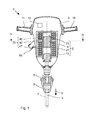
- Fig.1 shows a hand-held electric chisel 1 as an example of a chiseling machine tool.
- a magneto-pneumatic striking mechanism 2 generates by means of a a movement axis 3 guided racket 4 periodically or aperiodically blows in a direction of impact 5.
- a tool holder 6 stops on the movement axis 3 at the percussion 2 adjacent a chisel tool 7.
- the chisel tool 7 is movably guided in the tool holder 6 along the movement axis 3 and can in the direction of impact 5 driven by the blows in eg a subsoil penetrate.
- a lock 8 limits the axial movement of the chisel tool 7 in the tool holder 6.
- the lock 8 is, for example, a pivotable bracket and is preferably unlocked manually without tools to exchange the chisel tool 7 can.
- the striking mechanism 2 is arranged in a machine housing 9 .
- a handle 10 applied to the machine housing 9 allows the user to hold the electric chisel 1 and guide it during operation.
- a system switch 11 with which the user can operate the impact mechanism 2 is preferably attached to the handle 10 .
- the system switch 11 activates, for example, a controller 12 of the striking mechanism 2.
- Fig. 2 shows the magneto-pneumatic impact mechanism 2 in longitudinal section.
- the striking mechanism 2 has only two movable components: a racket 4 and an anvil 13.
- the racket 4 and the striker 13 lie on the common axis of movement 3; the striker 13 follows in the direction of impact 5 on the racket 4.
- the racket 4 is reciprocated between a beating point 14 and an upper turning point 15 on the movement axis 3 .
- the bat 4 strikes the striker 13 .
- the position of the impact point 14 along the axis is predetermined by the striker 13 .
- the striker 13 preferably rests in its home position 16 and preferably returns to this home position 16 after each strike before the striker 4 strikes the striker 13 a next time.
- This preferred operation is assumed for the following description.
- the magneto-pneumatic impact mechanism 2 has, in contrast to a conventional pneumatic percussion 2, a high tolerance to the actual position of the striker 13. This can be disengaged in a strike even in the direction of impact 5 relative to the basic position 16 .
- the basic position 16 thus indicates along the direction of impact 5 the earliest position at which the racket 4 can hit the striker 13 .
- Fig. 3 schematically illustrates the movement of the racket 4 and the striker 13 in three successive beats over time 19th
- the racket 4 In its rest position, the racket 4 typically abuts the striker 13 .
- For a stroke of the racket 4 is moved back against the direction of impact 5 and accelerated after reaching the upper inflection point 15 in the direction of impact 5 .
- the bat 4 bounces at the end of its movement in the direction of impact 5 in the impact point 14 on the striker 13.
- the striker 13 receives significantly more than half of the kinetic energy of the racket 4 and is deflected in the direction of impact 5 .
- the striker 13 pushes the chisel tool 7 against it in the direction of impact 5 in front of him into the ground.
- the striker 13 is in the basic position in the direction of impact 5 on a housing-fixed stop 20 .
- the stop 20 may for example contain a damping element.
- the exemplary striker 13 has radially projecting wings 21, which can rest against the stop 20 .
- the racket 4 is driven without contact by a magnetic primary drive 22 .
- the primary drive 22 raises the racket 4 against the direction of impact 5 .
- the prime mover 22 is preferably active only on the fly during the raising of the racket 4 to the upper inflection point 15 .
- the primary drive 22 accelerates the racket 4 after exceeding the upper inflection point 15 until reaching the impact point 14.
- the primary drive 22 can be activated at about the same time as the upper inflection point 15 is exceeded.
- the primary drive 22 remains active until impact.
- An air spring 23 supports the primary drive 22 during the movement of the racket 4 in the direction of impact 5, from the upper point of inflection to just before the impact point.
- the air spring 23 is arranged on the movement axis 3 in the direction of impact 5 in front of the racket 4 and acts on the racket 4th
- the racket 4 consists mainly of a cylindrical base body whose lateral surface 24 is parallel to the movement axis 3 .
- a front end face 25 points in the direction of impact 5.
- the front end face 25 is flat and covers the entire cross section of the racket 4.
- a rear end face 26 is preferably also flat.
- the racket 4 is inserted into a guide tube 27 .
- the guide tube 27 is coaxial with the movement axis 3 and has a cylindrical inner wall 28.
- the lateral surface 24 of the racket 4 abuts against the inner wall 28 .
- the racket 4 is forcibly guided in the guide tube 27 on the movement axis 3 .
- a cross section of the racket 4 and a Hollow cross section of the guide tube 27 are matched to a low running clearance precisely matched.
- the racket 4 closes like a flying seal the guide tube 27.
- a sealing ring 29 made of rubber can be used in the lateral surface 24 compensate for tolerances in manufacturing.
- the guide tube 27 is closed at its front in the direction of impact 5 .
- a closure 30 is inserted into the guide tube 27 , whose cross section corresponds to the hollow cross section of the guide tube 27 .
- the inwardly directed closure surface 31 is preferably flat and perpendicular to the movement axis 3.
- the closure 30 is mounted at a fixed distance 32 to the striker 13 resting in the basic position 16 .
- the cavity between the closure 30 and the striker 13, in the basic position 16, is the area of the guide tube 27 which is effective for the striker 4 and within which the striker 4 can move.
- the maximum stroke 18 is substantially the distance 32 less the length 33 of the racket 4th
- the one-sided closed guide tube 27 and the racket 4 close off a pneumatic chamber 34 .
- a volume of the pneumatic chamber 34 is proportional to a distance 35 between the closing surface 31 and the rear end surface 26 of the racket. The volume is variable due to the movement axis 3 movable racket 4 .
- the air compressed or decompressed upon movement in the pneumatic chamber 34 results in the action of the air spring 23.
- the maximum volume occupies the pneumatic chamber 34 at the point of impact 14 , ie when the club 4 hits the striker 13 .
- the pressure in the pneumatic chamber 34 is the lowest and advantageously equal to the ambient pressure.
- the potential energy of the air spring 23 is in the impact point 14 by definition equal to zero.
- the smallest volume reaches the pneumatic chamber 34 in the upper inflection point 15 of the racket 4; the pressure can rise to about 16 bar.
- the stroke of the striker 4 is limited by a control method to set the volume and pressure of the pneumatic chamber 34 at the upper inflection point 15 to a target value.
- the potential energy of the air spring 23 should be in the upper inflection point 15 in a narrow range of values, regardless of external influences. In particular, this makes the percussion mechanism 2 robust against the position of the striker 13 during impact, although its position has a great influence on the duration of flight of the striker 4 up to the upper inflection point 15 .
- the air spring 23 is provided with one or more ventilation openings 36 to compensate for losses in the amount of air in the air spring 23 .
- the ventilation openings 36 are closed by the bat 4 during the compression of the air spring 23 .
- the Bat 4 the vent openings 36 just before the impact point 14 free when the pressure in the air spring 23 differs by less than 50% of the ambient pressure.
- the beater 4 passes over the one vent 36 when it has moved away from the beating position by more than 5% of its stroke 18 .
- the primary drive 22 is based on reluctance forces acting on the club 4 .
- the main body of the racket 4 is made of a soft magnetic steel. Compared to a permanent magnet, the racket 4 is distinguished by its low coercive force of less than 4000 A / m, preferably less than 2500 A / m. An external magnetic field with this low field strength can already reverse polarization of the racket 4 . An applied external magnetic field pulls the magnetizable racket 4 into areas of highest field strength, regardless of their polarity.
- the primary drive 22 has along the movement axis 3 a cavity into which the guide tube 27 is inserted.
- the primary drive 22 creates a permanent magnetic field 37 and a two-part switchable magnetic field 38 in the cavity and within the guide tube .
- the magnetic fields 37, 38 divide the cavity and effective area of the guide tube 27 along the axis of travel 3 into an upper portion 39, a middle one Section 40 and a lower section 41.
- Field lines of the magnetic fields 37, 38 extend in the upper portion 39 and the lower portion 41 substantially parallel to the movement axis 3 and in the central portion 40 substantially perpendicular to the movement axis 3.
- the magnetic fields 37, 38 differ in their parallel or antiparallel orientation of the field lines to the direction of impact 5.
- the field lines (dash-dot pattern) of the permanent magnetic field 37 shown by way of example extend in the upper portion 39 of the guide tube 27 substantially antiparallel to the direction of impact 5 and in a lower portion 41 of the lead ungsrohrs 27 substantially parallel to the impact direction 5.
- the different running direction of the field lines of the permanent magnetic field 37 in the upper section 39 is compared to the running direction in the lower portion 41 substantially.
- the field lines of the switchable magnetic field 38 run during a phase (shown in phantom) within the upper portion 39 and lower portion 41 of the guide tube 27 largely in the direction of impact 5 and during another phase (not shown) within both sections 39, 41 substantially antiparallel to the direction of impact 5.
- the permanent magnetic field 37 and the switchable magnetic field 38 are thus destructively superposed in one of the two sections 39 and the other of the sections 41 constructively.
- the magnetic fields 37, 38 overlap constructively depends on a current switching cycle of the controller 12 from.
- An alternating reversal of the switchable magnetic field 38 drives the reciprocating movement of the racket 4.
- the permanent magnetic field 37 is generated by a radially magnetized ring magnet 42 of a plurality of permanent magnets 43 .
- Fig. 4 shows the ring magnet 42 in a section in the plane IV-IV.
- the exemplary permanent magnets 43 are preferably bar magnets.
- the permanent magnets 43 are oriented in the radial direction. Their magnetic field axes 44, ie from their south pole to north pole, are perpendicular to the movement axis 3.
- the permanent magnets 43 are all the same orientation, in the illustrated example, their north pole N to the axis of movement 3 and the south pole S away from the axis of movement 3 .
- In the circumferential direction between the permanent magnets 43 may be an air gap or a non-magnetizable material 45, for example plastic.
- the ring magnet 42 is arranged along the movement axis 3 between the closure surface 31 and the striker 13 .
- the ring magnet 42 is arranged asymmetrically, in particular closer to the sealing surface 31 than at the striker 13.
- the position of the ring magnet 42 divides the guide tube 27 along the scan axis 3, which is in the impact direction 5 in an upper section 39 in front of the ring magnet 42, and a lower portion 41, which is in the direction of impact 5 after the ring magnet 42 .
- the field lines in the upper section 39 extend largely in the opposite direction compared to the field lines in the lower section 41.
- the permanent magnets 43 preferably comprise an alloy of neodymium.
- the field strength at the poles of the permanent magnets 43 is preferably above 1 Tesla, for example up to 2 Tesla.
- the switchable magnetic field 38 is generated with an upper magnetic coil 46 and a lower magnetic coil 47 .
- the upper magnetic coil 46 is arranged in the direction of impact 5 in front of the ring magnet 42, preferably directly adjacent to the ring magnet 42 .
- the upper magnetic coil 46 encloses the upper portion 39 of the guide tube 27.
- the lower magnetic coil 47 is arranged in the direction of impact 5 after the ring magnet 42, preferably adjacent thereto, and surrounds the lower portion 41.
- the two magnetic coils 39 , 46 are in the same direction of rotation the movement axis 3 is traversed by a current 48 .
- the upper magnetic field 49 generated by the upper magnetic coil 46 and the lower magnetic field 50 generated by the magnetic coil 47 are oriented substantially parallel to the axis of movement 3 and both in the same direction along the axis of movement 3 , ie either the field lines of both magnetic fields 49, 50 inside of the guide tube 27 in the direction of impact 5 or against the direction of impact 5.
- the current 48 is from a controllable current source 51 in the magnetic coils 46, 47 fed.
- the two magnetic coils 46, 47 and the current source 51 are connected in series ( Fig. 5 ).
- a length 52, ie dimension along the axis of movement 3, of the lower magnetic coil 47 is preferably greater than the length 53 of the upper magnetic coil 46, the aspect ratio being in the range between 1.75: 1 to 2.25: 1.
- the respective magnitudes of the magnetic coils 46, 47 to the field strength of the upper magnetic field 49 and to the field strength of the lower magnetic field 50 within the guide tube 27 are preferably the same.
- the ratio of the number of cycles of the upper solenoid coil 46 to the number of the number of the lower magnetic coil 47 may correspond to the aspect ratio.
- Radial dimensions 54 and a surface density are preferably the same for both solenoids 46, 47 (without the other components of the percussion mechanism).
- a magnetic yoke 55 can guide the magnetic fields 37, 38 outside the guide tube 27 .
- the yoke 55 has, for example, a hollow cylinder or a cage of a plurality of ribs extending along the movement axis 3 , which surrounds the two magnet coils 46, 47 and the ring magnet 42 made of permanent magnets 43 .
- An annular upper end 56 of the yoke 55 covers the upper magnetic coil 46 against the direction of impact 5 from.
- An annular lower termination 57 adjoins the guide tube 27 at the level of the striker 13 .
- the lower end 57 covers the lower magnetic coil 47 in the direction of impact 5 from.
- the magnetic fields 37, 38 are guided in the upper portion 39 and the lower portion 41 parallel or anti-parallel to the movement axis 3 .
- a radial recirculation takes place in the lower portion 41 largely within the striker 13.
- the field lines are thus preferably substantially perpendicular to the end face 26 of the racket 4 and the striking surface 58 of the striker 13.
- the radial return in the upper portion 39 can ungroundung, ie the air, carried into the yoke 56 .
- the magnetic yoke 55 is made of a magnetizable material, preferably of electric sheet.
- the guide tube 27 is not magnetizable. Suitable materials for the guide tube 27 include chrome steel, alternatively aluminum or plastics.
- the closure 30 of the guide tube 27 is preferably made of a non-magnetizable material.
- the racket 4 preferably overlaps in each position with both magnetic coils 46, 47.
- the rear end face 26 projects into the upper magnetic coil 46 when the
- the ventilation opening 36 of the pneumatic chamber 34 is located at the axial height of the ring magnet 42 facing end of the upper solenoid 46 , The distance 35 to the ring magnet 42 is preferably less than 1 cm.
- a controller 12 of the striking mechanism 2 controls the current source 51 .
- the current source 51 adjusts the current 48 outputted by it to a desired value 60 predetermined by the controller 12 by means of an actuating signal 59 .
- the current source 51 preferably includes a control circuit 61 for stabilizing the output current 48 to the target value 60 .
- a tap measures the actual current 62.
- a differential amplifier 63 forms from the actual current 48 and the desired value 60 a manipulated variable 64, which is supplied to the current source 51 for driving the current output.
- the power source 51 is powered by a power supply 65, such as a power supply or a battery pack.
- the controller 12 switches the setpoint 60 and indirectly the current 48 during a reciprocating movement of the racket 4.
- Fig. 6 illustrates an exemplary repetitive switching pattern over time 19.
- the switching pattern is essentially subdivided into three different phases.
- One cycle begins with an active return phase 66.
- the club 4 is accelerated from the strike position against the direction of impact 5 .
- the active return phase 66 ends when the air spring 23 has reached a predetermined potential energy.
- the active return phase 66 is immediately followed by a resting phase 67 , which ends when the racket 4 reaches the upper turning point 15 .
- the acceleration phase 68 begins .
- the racket 4 is accelerated in the direction of impact 5 , preferably continuously until the racket 4 strikes the striker 13 .
- a pause 69 can be made after the acceleration phase 68 before the next active return phase 66 begins.
- the controller 12 initiates a new strike with an active return phase 66 .
- the controller 12 provides the regulated current source 51 with a first value 70 as the desired value 60 .
- the sign of the first value 70 specifies that the current 48 circulates in the magnet coils 47 in such a way that the magnetic field 49 of the upper magnet coil 46 constructively overlaps with the permanent magnetic field 37 in the upper section 39 of the guide tube 27 .
- the racket 4 is now accelerated in the upper portion 39 against the direction of impact 5 and against a force of the air spring 23 .
- the kinetic Energy of the bat 4 increases continuously. Due to the backward movement, the air spring 23 is compressed at the same time and the potential energy stored in it increases due to the volume work performed.
- the current 48 preferably passes through both magnetic coils 46, 47.
- the magnetic fields 37, 38 destructively overlap in the lower portion 41.
- the magnitude of the first value 70 may be selected such that the magnetic field 50 generated by the lower magnetic coil 47 is the permanent magnetic field 37 of the permanent magnets 43 destructively compensated.
- the magnetic field strength in the lower portion 41 is preferably lowered to zero or less than 10% of the magnetic field strength in the upper portion 39 .
- the current source 51 and the magnetic coils 46, 47 are designed for the current 48 with the current value of the first value 70 .
- the first value 70 may be kept constant during the active return phase 66 .
- the controller 12 triggers the end of the active return phase 66 based on a prediction of the potential energy of the air spring 23 at the upper inflection point 15.
- the primary drive 22 is deactivated, for example, when the potential energy reaches a target value without further assistance from the primary drive 22 ,
- the potential energy has already reached a part of the target value and the current kinetic energy of the racket 4 is converted to the upper inflection point 15 in the previously missing part of the target value. Losses in the conversion can be taken into account by a table 72 stored in the controller 12 .
- the target value is in the range between 25% and 40%, eg at least 30% and eg at most 37%, of the impact energy of the club 4.
- a forecasting device 73 continuously compares the operating conditions of the hammer mechanism 2.
- An exemplary forecast is based on a pressure measurement.
- the forecasting device 73 picks up the signals of the pressure sensor 74 .
- the measured pressure is compared with a threshold value.
- the predictor 73 outputs to the controller 12 a control signal 59 .
- the control signal 59 signals that when the primary drive 22 is switched off immediately, the potential energy reaches the target value.
- the controller 12 terminates the active return phase 66.
- the predictor 73 preferably loads the threshold from the stored lookup table 72.
- the lookup table 72 may contain exactly one threshold. Preferably, however, several are pre-determined for different operating conditions certain thresholds deposited. For example, threshold values for different temperatures may be stored in the pneumatic chamber 34 .
- the forecasting device 73 also receives a signal of a temperature sensor 75 in addition to the signal of the pressure sensor 74 . Depending on the latter, for example, the threshold value is selected.
- the forecasting device 73 can estimate the speed of the racket 4 from a pressure change.
- Lookup table 72 may include different thresholds for the current pressure for different speeds. Since a faster club 4 tends to compress the air spring 23 more, the threshold for a higher speed is lower than for a lower speed. Selecting the threshold depending on the speed or pressure change can improve the reproducibility of the target value.
- the end of the active return phase 66 is also the beginning of the idle phase 67.
- the controller 12 sets the setpoint 60 for the current 48 to zero.
- the switchable magnetic field 38 is switched off and the primary drive 22 is deactivated.
- the permanent magnetic field 37 acts on the racket 4 .
- the permanent magnetic field 37 has a field strength substantially constant along the movement axis 3 , it exerts little or no force on the beater 4 .
- the current 48 in the quiescent phase 67 can be set to a negative value to the setpoint value 60 .
- the amount of current 48 is small compared to that of the target value 60 , so as not to disturb the backward movement, eg less than 10%.
- the racket 4 is decelerated during the resting phase 67 by the air spring 23 to a standstill.
- the potential energy of the air spring 23 is thereby increased by a part of the kinetic energy of the racket 4 before the racket 4 comes to a standstill ie to the upper inflection point 15 .
- the sequence of the active return phase 66 and the resting phase 67 proves to be particularly energy efficient in the tested percussion structures, in particular turning off the current 48 to zero at the end of the active return phase 66.
- the efficiency of the primary drive 22 decreases with decreasing distance 35 of the racket 4 of the upper turning point 15.
- the racket 4 is as long as the primary drive 22 acts efficiently accelerated to a high speed. If the forecast shows that the club 4 will reach the desired upper turning point 15 without the primary drive 22 , the increasingly inefficient primary drive 22 disabled.
- the current 48 is lowered continuously or in several steps to zero.
- an adaptive adaptation of the trajectory of the racket 4 to reach the upper inflection point 15 can be made.
- the rest phase 67 preferably closes before reaching the upper inflection point 15 .
- the duration of the active return phase 66 results from the prognosis. Depending on the operation or even from beat to beat, the duration may vary. For example, the striker 13 does not reach its home position 16 prior to a strike , which requires the striker 4 to travel a greater distance for the next shot. For a fixed duration of the active return phase 66 , the absorbed kinetic energy for the club 4 would not be sufficient up to the desired upper turning point 15 against the force of the air spring 23 .
- the controller 12 triggers the end of the idle phase 67 based on reaching the upper inflection point 15. With the end of the idle phase 67 , the acceleration phase 68 begins .
- the controller 12 triggers the beginning of the acceleration phase 68 based on the reversal motion of the racquet 4.
- a position or motion sensor can directly detect the reverse movement of the racket 4 .
- the detection of the reverse motion is indirectly based on a pressure change in the pneumatic chamber 34.
- a pressure sensor 74 is coupled to the pneumatic chamber 34 .
- the pressure sensor 74 is, for example, a piezoresistive pressure sensor 74.
- the pressure sensor 74 may be arranged in the pneumatic chamber 34 or may be coupled to the pneumatic chamber 34 via an air channel.
- the pressure sensor 74 is preferably arranged on or in the closure 30 .
- the pressure sensor 74 is assigned an evaluation device 76 .
- the evaluation device 76 monitors a pressure change in the pneumatic chamber 34. As soon as the pressure change assumes a negative value, ie the pressure drops, the evaluation device 76 outputs to the controller 12 a control signal 77 indicating the reaching of the upper inflection point 15 by the beater 4 ,
- the pressure in the pneumatic chamber 34 may in the upper inflection point 15th measured and stored as the threshold in a table of the evaluation device 76 .
- the threshold value can be stored as a function of various operating conditions, in particular a temperature in the pneumatic chamber 34 .
- the evaluation device 76 determines the present operating condition, for example by querying a temperature sensor, and reads out the associated threshold value from the table. The two methods can be combined redundantly and output the control signal 77 separately.
- the controller 12 begins the acceleration phase 68 when the control signal 77 is received.
- the controller 12 sets the setpoint 60 for the current 48 to a second value 78.
- the sign of the second value 78 is selected such that the lower magnetic field 50 of the lower magnet coil 47 is structurally superposed with the permanent magnetic field 37 within the guide tube 27 . This results in a high field strength in the lower portion 41 of the guide tube 27.
- the current 48 is fed during the acceleration phase 68 in the lower magnetic coil 47 and preferably in the upper magnetic coil 46 .
- the permanent magnetic field 37 in the upper portion 39 is preferably attenuated or completely destructively balanced by the magnetic field 38 of the upper magnetic coil 46 within the guide tube 27 .
- the racket 4 is pulled into the stronger magnetic field in the lower portion 41 .
- the racket 4 undergoes an acceleration in the direction of impact 5 continuously during the acceleration phase 68.
- the kinetic energy reached up to the impact point 14 is approximately the impact energy of the racket 4.
- An alternative or additional determination of the reaching of the upper inflection point 15 is based on a change in the voltage induced in the upper magnet coil 46 due to the movement of the racket 4.
- the racket 4 may overlap with the upper yoke ring 56 before reaching the upper inflection point 15 .
- the magnetic field 49 of the ring magnet 42 flows in the upper area 39 almost closed without air gap on the racket 4 in the upper yoke 56.
- the magnetic field 50 of the ring magnet 42 flows in the lower portion 41 via a large air gap to the lower yoke ring 57.
- the air gap in the lower region 41 increases even further, whereby the magnetic flux increases proportionately in the upper region.
- the proportion of the magnetic flux in the upper region 39 decreases .
- the change in the magnetic flux induces a voltage in the upper magnetic coil 46 .
- Characteristic of the inflection point 15 is a change in the sign of the induced voltage.
- the current source 51 preferably regulates the current 48 before reaching the point of inflection 15 to zero, around the rest phase 67 observed.
- the control loop continuously adjusts the manipulated variable 64 to keep the current 48 against the induced voltage to zero. On the change of the sign of the induced voltage, the control loop 62 reacts with a much larger manipulated variable 64.
- the control signal 77 can thus be triggered, for example, when exceeding a threshold value by the manipulated variable 64 .
- the magnitude of the second value 78 is preferably adjusted so that the upper magnetic field 49 just destructively compensates for the permanent magnetic field 37 or decreases to at least 10% of its field strength.
- the current 48 in the magnetic coils 46, 47 increases at the beginning of the acceleration phase 68 to the desired value 60 .
- a switching edge is predetermined, for example, only by a time constant, which results from the inductance of the magnetic coils 46, 47 and the reaction of the racket.
- the controller 12 preferably keeps the set point 60 continuously at the second value 78 during the acceleration phase 68 .
- the air spring 23 supports the acceleration of the racket 4 in the direction of impact 5. In the air spring 23 stored potential energy is largely converted into kinetic energy of the racket 4 . In the impact point 14 , the air spring 23 is preferably completely relaxed. Near the point of impact 14 , the vent opening 36 is released by the racket 4 . The ventilation opening 36 leads to a weakening of the air spring 23 without lowering its effect on the racket 4 completely to zero. However, the air spring 23 has already transmitted significantly more than 90% of its potential energy to the racket 4 at this time.
- the controller 12 triggers the end of the acceleration phase 68 based on a rise 79 of the current 48 in the lower solenoid 47 and the current 48 fed from the current source 51 , respectively.
- electromagnetic induction occurs across the lower solenoid coil 47, a voltage drop against which the current source 51 feeds the current 48 .
- the voltage drop suddenly disappears.
- the current 48 increases briefly until the regulated current source 51 regulates the current 48 back to the desired value 60 .
- a current sensor 80 can detect the current 48 circulating in the lower magnetic coil 47 .
- An associated discriminator 81 compares the measured current 48 with a threshold value and outputs an end signal 82 when the threshold value is exceeded.
- the end signal 82 indicates to the controller 12 that the club 4 is on the striker 13 has pitched.
- the threshold value is selected, for example, as a function of the second value 78 , ie the setpoint value 60 for the acceleration phase 68.
- the threshold value may be 5% to 10% greater than the second value 78 .
- a rate of change of the current 48 with the current sensor 80 may be detected and compared against the discriminator 81 against a rate of change threshold.
- the current source 51 counteracts with its control circuit 61 the increase 79 of the current 48 in the circuit 83 .
- the manipulated variable 64 changes .
- the manipulated variable 64 can also be monitored. Both the absolute value or, preferably, a rate of change of the manipulated variable 64 can be compared with a threshold value and the end signal 82 can be output in response thereto.
- the controller 12 Upon receipt of the end signal 82 , the controller 12 terminates the acceleration phase 68.
- the setpoint 60 is set to zero. Accordingly, the current output of the current source 51 decreases to a current 48 equal to zero. The racket 4 is not further accelerated in the direction of impact 5 .
- the controller 12 may begin immediately after the acceleration phase 68 or after a break, the next active return phase 66 .
Landscapes
- Physics & Mathematics (AREA)
- Electromagnetism (AREA)
- Engineering & Computer Science (AREA)
- Mechanical Engineering (AREA)
- Power Engineering (AREA)
- Percussive Tools And Related Accessories (AREA)
Abstract
Description
- Die vorliegende Erfindung betrifft eine Werkzeugmaschine, die ein meißelndes Werkzeug antreiben kann. Ein Schläger wird unmittelbar durch Magnetspulen beschleunigt und schlägt auf das Werkzeug. Werkzeugmaschinen dieses Typs sind beispielsweise aus der Publikation
US 2010/0206593 bekannt. - Die erfindungsgemäße Werkzeugmaschine hat eine Werkzeugaufnahme, die eingerichtet ist ein meißelndes Werkzeug längs einer Bewegungsachse beweglich zu lagern. Ein magneto-pneumatisches Schlagwerk beinhaltet einen primären Antrieb, der um die Bewegungsachse angeordnet und in Schlagrichtung aufeinanderfolgend eine erste Magnetspule, einen Ringmagneten und eine zweite Magnetspule aufweist. Das Schlagwerk hat auf der Bewegungsachse innerhalb der Magnetspulen, und in Schlagrichtung aufeinanderfolgend einen Schläger und einen Döpper. Eine Luftfeder wirkt in Schlagrichtung auf den Schläger. Die Luftfeder kann beispielsweise teilweise oder vollständig innerhalb der ersten Magnetspule angeordnet sein. Der Ringmagnet ist permanent magnetisch und bezogen auf die Bewegungsachse radial magnetisiert. Der Ringmagnet ist beispielsweise aus mehreren Permanentmagneten zusammengesetzt, die alle mit einem Magnetpol, z.B. Nordpol (N), der Bewegungsachse zugewandt und mit einem anderen Magnetpol, z.B. Südpol (S) von der Bewegungsachse abgewandt ausgerichtet sind.
- Die im Wesentlichen längs der radialen Richtung orientierten Permanentmagnete erzeugen ein Magnetfeld, welches innerhalb der ersten Magnetspule und der zweiten Magnetspule in die entgegengesetzte Richtung läuft. Diese Asymmetrie kann genutzt werden, um die Magnetfeldstärke innerhalb der beiden Magnetspulen gegenphasig auf einen hohen und einen geringen Wert zu setzen. Der Gradient der Magnetfeldstärke bewegt den Schläger basierend auf der Reluktanzkraft.
- Eine Ausgestaltung sieht vor, dass ein in die erste Magnetspule eingespeister Strom und ein in die zweite Magnetspule eingespeister Strom die gleiche Umlaufrichtung um die Bewegungsachse aufweisen. Die von der ersten Magnetspule und von der zweiten Magnetspule erzeugten Magnetfelder sind beide parallel oder beide antiparallel zu der Schlagrichtung orientiert.
- Eine Ausgestaltung sieht vor, dass eine Steuerung die Magnetspulen, in alternierenden Phasen, ansteuert. Ein von der ersten Magnetspule innerhalb der ersten Magnetspule erzeugtes erstes Magnetfeld ist in einer ersten Phase konstruktiv und in einer zweiten Phase destruktiv mit dem Magnetfeld des Ringmagnets überlagert ist und ein von der zweiten Magnetspule innerhalb der zweiten Magnetspule erzeugtes zweites Magnetfeld ist in der ersten Phase destruktiv und der zweiten Phase konstruktiv mit dem Magnetfeld des Ringmagnets überlagert.
- Der Schläger kann aus einem weichmagnetischen Material sein. Der Schläger erzeugt selbst kein Magnetfeld. Eine Restmagnetisierung des Schlägers klingt schnell ab oder ist von der Feldstärke um wenigstens eine Größenordnung geringer als die Feldstärke der Magnetspulen oder des Ringmagnets. Der Schläger wird basierend auf einer Reluktanzkraft von den Magnetfeldern getrieben. Der Döpper ist vorzugsweise ebenfalls aus einem weichmagnetischen Material.
- Eine Ausgestaltung sieht vor, dass der Döpper in die zweite Magnetspule oder in ein an die zweite Magnetspule in Schlagrichtung anliegendes Joch hineinragt. Der magnetisierbare Döpper lenkt das Magnetfeld. Das von der zweiten Magnetspule erzeugte Magnetfeld tritt im Wesentlichen parallel zu der Schlagrichtung aus dem Döpper aus, d.h. verläuft im Wesentlichen senkrecht zu der Stirnfläche des Döpper. Das von dem Ringmagnet erzeugte Magnetfeld tritt ebenfalls im Wesentlichen senkrecht zu der Stirnfläche in den Döpper ein. Hierdurch ist eine hohe Feldstärke nahe der Stirnfläche möglich.
- Eine Ausgestaltung sieht vor, dass die Luftfeder durch einen stationären Verschluss entgegen der Schlagrichtung abgeschlossen ist. Der stationäre Verschluss ist gegenüber den Magnetspulen, der Werkzeugaufnahme etc. unbeweglich. Die pneumatische Kammer der Luftfeder ist bis auf eine Belüftungsöffnung von der Umgebung isoliert. Die Belüftungsöffnung ist auf axialer Höhe eines dem Ringmagnet zugewandten Ende der ersten Magnetspule.
- Eine Ausgestaltung sieht vor, dass der Schläger in jeder Stellung teilweise mit wenigstens einer der Magnetspulen, und teilweise mit dem Ringmagnet überlappt. Der Schläger kann vorzugsweise in jeder Stellung mit einem Teil in die erste Magnetspule und mit einem anderen Teil in die zweite Magnetspule hineinragen.
- Eine Ausgestaltung sieht vor, dass eine erste Länge der ersten Magnetspule geringer als eine zweite Länge der zweiten Magnetspule ist, insbesondere liegt ein Verhältnis der zweiten Länge zu der ersten Länge zwischen 1,75 bis 2,25. Die Asymmetrie erweist sich als günstiger für eine hohe Schlagenergie.
- Eine Ausgestaltung sieht vor, dass die erste Magnetspule, der Ringmagnet und die zweite Magnetspule um ein zu der Bewegungsachse koaxial ausgerichtetes Führungsrohr angeordnet sind und die Luftfeder, der Schläger und der Döpper innerhalb des Führungsrohrs angeordnet sind.
- Die nachfolgende Beschreibung erläutert die Erfindung anhand von exemplarischen Ausführungsformen und Figuren. In den Figuren zeigen:
-
Fig. 1 einen Elektromeißel -
Fig. 2 ein Schlagwerk des Elektromeißels -
Fig. 3 Bewegung von Schläger und Döpper -
Fig. 4 Schnitt durch das Schlagwerk in der Ebene IV-IV -
Fig. 5 elektrische Verschaltung des Schlagwerks -
Fig. 6 Steuerungsdiagramm - Gleiche oder funktionsgleiche Elemente werden durch gleiche Bezugszeichen in den Figuren indiziert, soweit nicht anders angegeben.
-
Fig.1 zeigt einen handgehaltenen Elektromeißel 1 als Beispiel für eine meißelnde Werkzeugmaschine. Ein magneto-pneumatisches Schlagwerk 2 erzeugt mittels eines auf einer Bewegungsachse 3 geführten Schlägers 4 periodisch oder aperiodisch Schläge in eine Schlagrichtung 5. Eine Werkzeugaufnahme 6 hält auf der Bewegungsachse 3 an dem Schlagwerk 2 anliegend ein Meißelwerkzeug 7. Das Meißelwerkzeug 7 ist in der Werkzeugaufnahme 6 längs der Bewegungsachse 3 beweglich geführt und kann in Schlagrichtung 5 angetrieben von den Schlägen in z.B. einen Untergrund eindringen. Eine Verriegelung 8 begrenzt die axiale Bewegung des Meißelwerkzeuges 7 in der Werkzeugaufnahme 6. Die Verriegelung 8 ist beispielsweise ein schwenkbarer Bügel und ist vorzugsweise ohne Hilfsmittel manuell entriegelbar, um das Meißelwerkzeug 7 austauschen zu können. - Das Schlagwerk 2 ist in einem Maschinengehäuse 9 angeordnet. Ein an dem Maschinengehäuse 9 angelegter Handgriff 10 ermöglicht dem Anwender den Elektromeißel 1 zu halten und im Betrieb zu führen. Ein Systemschalter 11, mit welchem der Anwender das Schlagwerk 2 in Betrieb nehmen kann, ist vorzugsweise am Handgriff 10 angebracht. Der Systemschalter 11 aktiviert beispielsweise eine Steuerung 12 des Schlagwerks 2.
-
Fig. 2 zeigt das magneto-pneumatisches Schlagwerk 2 im Längsschnitt. Das Schlagwerk 2 hat nur zwei bewegliche Komponenten: einen Schläger 4 und einen Döpper 13. Der Schläger 4 und der Döpper 13 liegen auf der gemeinsamen Bewegungsachse 3; der Döpper 13 folgt in Schlagrichtung 5 auf den Schläger 4. Der Schläger 4 wird zwischen einem Schlagpunkt 14 und einem oberen Wendepunkt 15 auf der Bewegungsachse 3 hin- und herbewegt. - Bei dem Schlagpunkt 14 trifft der Schläger 4 auf den Döpper 13 auf. Die Position des Schlagpunkt 14 längs der Achse ist durch den Döpper 13 vorgegeben. Der Döpper 13 ruht vorzugsweise in seiner Grundstellung 16 und kehrt vorzugsweise nach jedem Schlag in diese Grundstellung 16 zurück, bevor der Schläger 4 ein nächstes Mal auf den Döpper 13 aufschlägt. Dieser bevorzugte Betrieb wird für die nachfolgende Beschreibung unterstellt. Das magneto-pneumatische Schlagwerk 2 hat jedoch, im Gegensatz zu einem herkömmlichen pneumatischen Schlagwerk 2, eine hohe Toleranz gegenüber der tatsächlichen Position des Döppers 13. Dieser kann bei einem Schlag noch in Schlagrichtung 5 gegenüber der Grundstellung 16 ausgerückt sein. Die Grundstellung 16 gibt somit längs der Schlagrichtung 5 die früheste Position an, an welcher der Schläger 4 auf den Döpper 13 aufschlagen kann.
- Der Abstand 17 des Schlägers 4 zum Döpper 13 ist im oberen Wendepunkt 15 am größten, eine dabei von dem Schläger 4 zurückgelegte Distanz wird nachfolgend als Hub 18 bezeichnet.
Fig. 3 illustriert schematisch die Bewegung des Schlägers 4 und des Döppers 13 bei drei aufeinanderfolgenden Schlägen über die Zeit 19. - In seiner Ruhestellung liegt der Schläger 4 typischerweise an dem Döpper 13 an. Für einen Schlag wird der Schläger 4 gegen die Schlagrichtung 5 zurückbewegt und nach Erreichen des oberen Wendepunkts 15 in Schlagrichtung 5 beschleunigt. Der Schläger 4 prallt am Ende seiner Bewegung in Schlagrichtung 5 im Schlagpunkt 14 auf den Döpper 13. Der Döpper 13 nimmt deutlich mehr als die Hälfte der kinetischen Energie des Schlägers 4 auf und wird in Schlagrichtung 5 ausgelenkt. Der Döpper 13 schiebt das an ihm anliegende Meißelwerkzeug 7 in Schlagrichtung 5 vor sich her in den Untergrund. Der Anwender presst das Schlagwerk 2 in Schlagrichtung 5 gegen den Untergrund, wodurch der Döpper 13, vorzugsweise mittelbar durch das Meißelwerkzeug 7, in seine Grundstellung 16 zurückgeschoben wird. Der Döpper 13 liegt in der Grundstellung in Schlagrichtung 5 an einem gehäusefesten Anschlag 20 an. Der Anschlag 20 kann beispielsweise ein Dämpfelement enthalten. Der beispielhafte Döpper 13 hat radial vorstehende Flügel 21, welche an dem Anschlag 20 anliegen können.
- Der Schläger 4 wird berührungslos von einem magnetischen, primären Antrieb 22 angetrieben. Der primäre Antrieb 22 hebt den Schläger 4 entgegen der Schlagrichtung 5 an. Wie nachfolgend ausgeführt ist der primäre Antrieb 22 vorzugsweise nur zeifinieise während des Anhebens des Schlägers 4 zu dem oberen Wendepunkt 15 aktiv. Der primäre Antrieb 22 beschleunigt den Schläger 4 nach Überschreiten des oberen Wendepunkt 15 bis zum Erreichen des Schlagpunkts 14. Der primäre Antrieb 22 kann etwa zeitgleich mit dem Überschreiten des oberen Wendepunkts 15 aktiviert werden. Vorzugsweise bleibt der primäre Antrieb 22 bis zum Schlag aktiv. Eine Luftfeder 23 unterstützt den primären Antrieb 22 während der Bewegung des Schlägers 4 in Schlagrichtung 5, ab dem oberen Wendepunkt bis kurz vor dem Schlagpunkt. Die Luftfeder 23 ist auf der Bewegungsachse 3 in Schlagrichtung 5 vor dem Schläger 4 angeordnet und wirkt auf den Schläger 4.
- Der Schläger 4 besteht hauptsächlich aus einem zylindrischen Grundkörper, dessen Mantelfläche 24 parallel zu der Bewegungsachse 3 ist. Eine vordere Stirnfläche 25 weist in Schlagrichtung 5. Die vordere Stirnfläche 25 ist eben und überdeckt den gesamten Querschnitt des Schlägers 4. Eine hintere Stirnfläche 26 ist vorzugsweise ebenfalls eben. Der Schläger 4 ist in ein Führungsrohr 27 eingesetzt. Das Führungsrohr 27 ist koaxial zu der Bewegungsachse 3 und hat eine zylindrische Innenwand 28. Die Mantelfläche 24 des Schlägers 4 liegt an der Innenwand 28 an. Der Schläger 4 ist in dem Führungsrohr 27 auf der Bewegungsachse 3 zwangsgeführt. Ein Querschnitt des Schlägers 4 und ein Hohlquerschnitt des Führungsrohrs 27 sind bis auf ein geringes Laufspiel passgenau aufeinander abgestimmt. Der Schläger 4 verschließt gleich einer fliegenden Dichtung das Führungsrohr 27. Ein Dichtungsring 29 aus Gummi kann in die Mantelfläche 24 eingesetzt Toleranzen in der Fertigung ausgleichen.
- Das Führungsrohr 27 ist an seinem in Schlagrichtung 5 vorderen Ende geschlossen. Bei der beispielhaften Ausführungsform ist ein Verschluss 30 in das Führungsrohr 27 eingesetzt, dessen Querschnitt dem Hohlquerschnitt des Führungsrohrs 27 entspricht. Die nach innen gerichtete Verschlussfläche 31 ist vorzugsweise eben und senkrecht zu der Bewegungsachse 3. Der Verschluss 30 ist in einem festen Abstand 32 zu dem in der Grundstellung 16 ruhenden Döpper 13 angebracht. Der Hohlraum zwischen dem Verschluss 30 und dem Döpper 13, in Grundstellung 16, ist der für den Schläger 4 effektive Bereich des Führungsrohrs 27, innerhalb dem der Schläger 4 sich bewegen kann. Der maximale Hub 18 ist im wesentlichen der Abstand 32 abzüglich der Länge 33 des Schlägers 4.
- Das einseitig geschlossene Führungsrohr 27 und der Schläger 4 schließen eine pneumatische Kammer 34 ab. Ein Volumen der pneumatischen Kammer 34 ist proportional zu einem Abstand 35 zwischen der Verschlussfläche 31 und der hinteren Stirnfläche 26 des Schlägers. Das Volumen ist aufgrund des längs der Bewegungsachse 3 beweglichen Schlägers 4 variabel. Die bei einer Bewegung in der pneumatischen Kammer 34 komprimierte oder dekomprimierte Luft ergibt die Wirkung der Luftfeder 23. Das maximale Volumen nimmt die pneumatische Kammer 34 im Schlagpunkt 14 ein, d.h. wenn der Schläger 4 auf den Döpper 13 trifft. Der Druck in der pneumatischen Kammer 34 ist hierbei am geringsten und vorteilhafterweise gleich dem Umgebungsdruck. Die potentielle Energie der Luftfeder 23 sei im Schlagpunkt 14 definitionsgemäß gleich Null. Das geringste Volumen erreicht die pneumatische Kammer 34 im oberen Wendepunkt 15 des Schlägers 4; der Druck kann auf etwa 16 bar ansteigen. Der Hub des Schlägers 4 wird durch ein Steuerungsverfahren begrenzt, um das Volumen und den Druck der pneumatischen Kammer 34 im oberen Wendepunkt 15 auf einen Zielwert einzustellen. Die potentielle Energie der Luftfeder 23 soll im oberen Wendepunkt 15 in einem engen Wertebereich liegen, unabhängig von äußeren Einflüssen. Insbesondere wird hierdurch das Schlagwerk 2 robust gegenüber der Position des Döppers 13 beim Schlag, obwohl dessen Position einen großen Einfluss auf die Flugdauer des Schlägers 4 bis zu dem oberen Wendepunkt 15 hat.
- Die Luftfeder 23 ist mit einer oder mehreren Belüftungsöffnungen 36 versehen, um Verluste der Luftmenge in der Luftfeder 23 auszugleichen. Die Belüftungsöffnungen 36 sind während der Kompression der Luftfeder 23 durch den Schläger 4 verschlossen. Vorzugsweise gibt der Schläger 4 die Belüftungsöffnungen 36 kurz vor dem Schlagpunkt 14 frei, wenn der Druck in der Luftfeder 23 sich um weniger als 50 % von dem Umgebungsdruck unterscheidet. Bei der beispielhaften Ausgestaltung überfährt der Schläger 4 die eine Belüftungsöffnung 36, wenn er sich um mehr als 5 % seines Hubs 18 von der Schlagposition entfernt hat.
- Der primäre Antrieb 22 basiert auf Reluktanzkräften, welche auf den Schläger 4 wirken. Der Grundkörper des Schlägers 4 ist aus einem weichmagnetischen Stahl. Gegenüber einem Permanentmagnet zeichnet sich der Schläger 4 durch seine geringe Koerzitivfeldstärke von weniger als 4000 A/m, vorzugsweise weniger als 2500 A/m, aus. Ein externes Magnetfeld mit dieser geringen Feldstärke kann bereits eine Polarisation des Schlägers 4 umpolen. Ein angelegtes externes Magnetfeld zieht den magnetisierbaren Schläger 4 in Bereiche höchster Feldstärke, unabhängig von deren Polarität.
- Der primäre Antrieb 22 hat längs der Bewegungsachse 3 einen Hohlraum, in den das Führungsrohr 27 eingesetzt ist. Der primäre Antrieb 22 erzeugt in dem Hohlraum und innerhalb des Führungsrohrs ein permanentes Magnetfeld 37 und ein zweiteiliges schaltbares Magnetfeld 38. Die Magnetfelder 37, 38 unterteilen den Hohlraum und den effektiven Bereich des Führungsrohrs 27 längs der Bewegungsachse 3 in einen oberen Abschnitt 39, einen mittleren Abschnitt 40 und einen unteren Abschnitt 41. Feldlinien der Magnetfelder 37, 38 verlaufen in dem oberen Abschnitt 39 und dem unteren Abschnitt 41 weitgehend parallel zu der Bewegungsachse 3 und in dem mittleren Abschnitt 40 weitgehend senkrecht zu der Bewegungsachse 3. Die Magnetfelder 37, 38 unterscheiden sich in ihrer parallelen oder antiparallelen Orientierung der Feldlinien zu der Schlagrichtung 5. Die ausschnittsweise beispielhaft dargestellten Feldlinien (Strich-Punkt-Muster) des permanenten Magnetfeldes 37 verlaufen in dem oberen Abschnitt 39 des Führungsrohrs 27 weitgehend antiparallel zu der Schlagrichtung 5 und in einem unteren Abschnitt 41 des Führungsrohrs 27 weitgehend parallel zu der Schlagrichtung 5. Für die Funktion des Schlagwerks 2 ist die unterschiedliche Laufrichtung der Feldlinien des permanenten Magnetfeldes 37 im oberen Abschnitt 39 verglichen zu der Laufrichtung im unteren Abschnitt 41 wesentlich. Die Feldlinien des schaltbaren Magnetfelds 38 verlaufen während einer Phase (gestrichelt dargestellt) innerhalb des oberen Abschnitts 39 und unteren Abschnitts 41 des Führungsrohrs 27 weitgehend in Schlagrichtung 5 und während einer anderen Phase (nicht dargestellt) innerhalb beider Abschnitte 39, 41 weitgehend antiparallel zu der Schlagrichtung 5. Das permanente Magnetfeld 37 und das schaltbare Magnetfeld 38 überlagern sich somit in einem der beiden Abschnitte 39 destruktiv und dem anderen der Abschnitte 41 konstruktiv. In welchem der Abschnitte 39 sich die Magnetfelder 37, 38 konstruktiv überlagern hängt von einem aktuellen Schaltzyklus der Steuerung 12 ab. Der Schläger 4 wird jeweils in den Abschnitt 39, 41 mit konstruktiver Überlagerung gezogen. Eine alternierende Umpolung des schaltbaren Magnetfeldes 38 treibt die Hin-und-her-Bewegung des Schlägers 4.
- Das permanente Magnetfeld 37 wird durch einen radial magnetisierten Ringmagnet 42 aus mehreren Permanentmagneten 43 erzeugt.
Fig. 4 zeigt den Ringmagnet 42 in einem Schnitt in der Ebene IV-IV. Die beispielhaften Permanentmagnete 43 sind vorzugsweise Stabmagnete. Die Permanentmagnete 43 sind in radialer Richtung orientiert. Ihre Magnetfeldachsen 44, d.h. von deren Südpol zu Nordpol, stehen senkrecht auf der Bewegungsachse 3. Die Permanentmagnete 43 sind alle gleich orientiert, in dem dargestellten Beispiel weist ihr Nordpol N zu der Bewegungsachse 3 hin und der Südpol S von der Bewegungsachse 3 weg. In Umfangsrichtung zwischen den Permanentmagneten 43 kann ein Luftspalt oder ein nicht-magnetisierbares Material 45, z.B. Kunststoff sein. Der Ringmagnet 42 ist längs der Bewegungsachse 3 zwischen der Verschlussfläche 31 und dem Döpper 13 angeordnet. Vorzugsweise ist der Ringmagnet 42 asymmetrisch angeordnet, insbesondere näher an der Verschlussfläche 31 als an dem Döpper 13. Die Position des Ringmagnets 42 unterteilt das Führungsrohr 27 längs der Bewegungsachse 3 in einen oberen Abschnitt 39, welcher in Schlagrichtung 5 vor dem Ringmagnet 42 ist, und einen unteren Abschnitt 41, welcher in Schlagrichtung 5 nach dem Ringmagnet 42 ist. Die Feldlinien verlaufen in dem oberen Abschnitt 39 weitgehend in die entgegengesetzte Richtung verglichen zu den Feldlinien in dem unteren Abschnitt 41. Die Permanentmagnete 43 enthalten vorzugsweise eine Legierung aus Neodym. Die Feldstärke an den Polen der Permanentmagnete 43 liegt vorzugsweise oberhalb von 1 Tesla, z.B. bis 2 Tesla. - Das schaltbare Magnetfeld 38 wird mit einer oberen Magnetspule 46 und einer unteren Magnetspule 47 erzeugt. Die obere Magnetspule 46 ist in Schlagrichtung 5 vor dem Ringmagnet 42, vorzugsweise unmittelbar an dem Ringmagnet 42 anliegend, angeordnet. Die obere Magnetspule 46 umschließt den oberen Abschnitt 39 des Führungsrohrs 27. Die untere Magnetspule 47 ist in Schlagrichtung 5 nach dem Ringmagnet 42, vorzugsweise an diesem anliegend, angeordnet und umschließt den unteren Abschnitt 41. Die beiden Magnetspulen39, 46 werden in gleicher Umlaufrichtung um die Bewegungsachse 3 von einem Strom 48 durchflossen. Das von der oberen Magnetspule 46 erzeugte obere Magnetfeld 49 und das von der Magnetspule 47 erzeugte untere Magnetfeld 50 sind weitgehend parallel zu der Bewegungsachse 3 und beide in die gleiche Richtung längs der Bewegungsachse 3 orientiert, d.h. entweder verlaufen die Feldlinien beider Magnetfelder 49, 50 innerhalb des Führungsrohrs 27 in Schlagrichtung 5 oder entgegen der Schlagrichtung 5. Der Strom 48 wird von einer steuerbaren Stromquelle 51 in die Magnetspulen 46, 47 eingespeist. Vorzugsweise sind die beiden Magnetspulen 46, 47 und die Stromquelle 51 in Serie geschaltet (
Fig. 5 ). - Eine Länge 52, d.h. Abmessung längs der Bewegungsachse 3, der unteren Magnetspule 47 ist vorzugsweise größer als die Länge 53 der oberen Magnetspule 46, das Längenverhältnis liegt im Bereich zwischen 1,75:1 bis 2,25:1. Die jeweiligen Beträge der Magnetspulen 46, 47 zu der Feldstärke des oberen Magnetfelds 49 bzw. zu der Feldstärke des unteren Magnetfelds 50 innerhalb des Führungsrohrs 27 sind vorzugsweise gleich. Das Verhältnis der Wcklungszahlen der oberen Magnetspule 46 zu der Wcklungszahl der unteren Magnetspule 47 kann dem Längenverhältnis entsprechen. Radiale Abmessungen 54 und eine Stromflächendichte sind vorzugsweise für beide Magnetspulen 46, 47 (ohne die anderen Komponenten des Schlagwerks) gleich.
- Ein magnetisches Joch 55 kann die Magnetfelder 37, 38 außerhalb des Führungsrohrs 27 leiten. Das Joch 55 hat beispielsweise einen Hohlzylinder oder einen Käfig aus mehreren längs der Bewegungsachse 3 verlaufenden Rippen, der die beiden Magnetspulen 46, 47 und den Ringmagnet 42 aus Permanentmagneten 43 umgibt. Ein ringförmiger oberer Abschluss 56 des Jochs 55 deckt die obere Magnetspule 46 entgegen der Schlagrichtung 5 ab. Ein ringförmiger unterer Abschluss 57 grenzt auf der Höhe des Döppers 13 an das Führungsrohr 27 an. Der untere Abschluss 57 deckt die untere Magnetspule 47 in Schlagrichtung 5 ab. Die Magnetfelder 37, 38 werden in dem oberen Abschnitt 39 und dem unteren Abschnitt 41 parallel oder antiparallel zu der Bewegungsachse 3 geführt. Die Magnetfelder 37, 38 von dem Joch 55, insbesondere der ringförmigen Abschlüsse 56, 57 in radialer Richtung eingespeist. Eine radiale Rückführung erfolgt in dem unteren Abschnitt 41 weitgehend innerhalb des Döppers 13. Die Feldlinien stehen somit vorzugsweise weitgehend senkrecht auf der Stirnfläche 26 des Schlägers 4 und der Schlagfläche 58 des Döppers 13. Die radiale Rückführung in dem oberen Abschnitt 39 kann ungeführt, d.h. über die Luft, in das Joch 56 erfolgen.
- Das magnetische Joch 55 ist aus einem magnetisierbaren Material, vorzugsweise aus Elektroblech. Das Führungsrohr 27 ist nicht magnetisierbar. Geeignete Materialien für das Führungsrohr 27 umfassen Chromstahl, alternativ Aluminium oder Kunststoffe. Der Verschluss 30 des Führungsrohrs 27 ist vorzugsweise aus einem nicht-magnetisierbaren Material.
- Der Schläger 4 überlappt vorzugsweise in jeder seiner Stellung mit beiden Magnetspulen 46, 47. Insbesondere ragt die hintere Stirnfläche 26 in die obere Magnetspule 46, wenn der
- Schläger 4 an dem Döpper 13 anliegt oder zumindest bis in den Ringmagnet 42. Die hintere Stirnfläche 26 überragt wenigstens die axiale Mitte des Ringmagnets 42. Die Belüftungsöffnung 36 der pneumatischen Kammer 34 ist auf axialer Höhe eines dem Ringmagnet 42 zugewandten Endes der oberen Magnetspule 46 angeordnet. Der Abstand 35 zu dem Ringmagnet 42 ist vorzugsweise geringer als 1 cm.
- Eine Steuerung 12 des Schlagwerks 2 steuert die Stromquelle 51 an. Die Stromquelle 51 stellt den von ihr ausgegebenen Strom 48 auf einen durch die Steuerung 12 mittels eines Stellsignals 59 vorgegebenen Sollwert 60 ein. Die Stromquelle 51 beinhaltet vorzugsweise einen Regelkreis 61, um den ausgegeben Strom 48 auf den Sollwert 60 zu stabilisieren. Ein Abgriff misst den Ist-Strom 62. Ein Differenzverstärker 63 bildet aus dem Ist-Strom 48 und dem Sollwert 60 eine Stellgröße 64, welche der Stromquelle 51 zum Ansteuern der Stromabgabe zugeführt ist. Die Stromquelle 51 wird von einer Stromversorgung 65, beispielsweise einem Netzanschluss oder einem Batteriepaket, gespeist.
- Die Steuerung 12 schaltet den Sollwert 60 und mittelbar den Strom 48 während einer Hin-und-Herbewegung des Schlägers 4.
Fig. 6 illustriert ein beispielhaftes sich wiederholendes Schaltmuster über die Zeit 19. Das Schaltmuster ist im wesentlichen in drei unterschiedliche Phasen unterteilt. Ein Zyklus beginnt mit einer aktiven Rückholphase 66. Während der aktiven Rückholphase 66 wird der Schläger 4 ausgehend von der Schlagposition entgegen die Schlagrichtung 5 beschleunigt. Die aktive Rückholphase 66 endet, wenn die Luftfeder 23 eine vorgegebene potentielle Energie erreicht hat. An die aktive Rückholphase 66 schließt sich unmittelbar eine Ruhephase 67 an, die endet wenn der Schläger 4 den oberen Wendepunkt 15 erreicht. Während oder nachdem der Schläger 4 den oberen Wendepunkt 15 überschreitet, beginnt die Beschleunigungsphase 68. Während der Beschleunigungsphase 68 wird der Schläger 4 in Schlagrichtung 5 beschleunigt, vorzugsweise durchgehend bis der Schläger 4 auf den Döpper 13 aufschlägt. Je nach der gewünschten Schlagfrequenz kann nach der Beschleunigungsphase 68 eine Pause 69 erfolgen, bevor die nächste aktive Rückholphase 66 beginnt. - Die Steuerung 12 leitet einen neuen Schlag mit einer aktiven Rückholphase 66 ein. Die Steuerung 12 gibt der geregelten Stromquelle 51 einen ersten Wert 70 als Sollwert 60 vor. Das Vorzeichen des ersten Werts 70 legt fest, dass der Strom 48 derart in den Magnetspulen 47 umläuft, dass sich das Magnetfeld 49 der oberen Magnetspule 46 konstruktiv mit dem permanenten Magnetfeld 37 in dem oberen Abschnitt 39 des Führungsrohrs 27 überlagert. Der Schläger 4 wird nun in den oberen Abschnitt 39 entgegen der Schlagrichtung 5 und entgegen eine Kraft der Luftfeder 23 beschleunigt. Die kinetische Energie des Schlägers 4 nimmt kontinuierlich zu. Aufgrund der Rückwärtsbewegung wird zugleich die Luftfeder 23 komprimiert und die in ihr gespeicherte potentielle Energie steigt aufgrund verrichteter Volumenarbeit an.
- Der Strom 48 durchläuft vorzugsweise beide Magnetspulen 46, 47. Vorzugsweise überlagern sich die Magnetfelder 37, 38 destruktiv in dem unteren Abschnitt 41. Der Betrag des ersten Werts 70 kann derart gewählt sein, dass das von der unteren Magnetspule 47 erzeugte Magnetfeld 50 das permanente Magnetfeld 37 der Permanentmagnete 43 destruktiv kompensiert. Die Magnetfeldstärke ist in dem unteren Abschnitt 41 vorzugsweise auf Null oder auf weniger als 10 % der Magnetfeldstärke in dem oberen Abschnitt 39 abgesenkt. Die Stromquelle 51 und die Magnetspulen 46, 47 sind für den Strom 48 mit der Stromstärke des ersten Werts 70 ausgelegt. Der erste Wert 70 kann während der aktiven Rückholphase 66 konstant gehalten sein.
- Die Steuerung 12 triggert das Ende der aktiven Rückholphase 66 basierend auf einer Prognose über die potentielle Energie der Luftfeder 23 im oberen Wendepunkt 15. Der primäre Antrieb 22 wird beispielsweise deaktiviert, wenn die potentielle Energie einen Zielwert ohne weitere Unterstützung durch den primären Antrieb 22 erreichen wird. Hierbei wird berücksichtigt, dass zum Zeitpunkt 71 des Abschaltens des primären Antriebs 22 die potentielle Energie bereits einen Teil des Zielwerts erreicht hat und die aktuelle kinetische Energie des Schlägers 4 bis zum oberen Wendepunkt 15 in den bisher fehlenden Teil des Zielwerts umgewandelt wird. Verluste bei der Wandlung können durch in einer in der Steuerung 12 abgelegten Tabelle 72 berücksichtigt sein. Der Zielwert liegt im Bereich zwischen 25% und 40 %, z.B. wenigstens 30 % und z.B. höchstens 37%, der Schlagenergie des Schlägers 4.
- Eine Prognoseeinrichtung 73 vergleicht fortwährend die Betriebsbedingungen des Schlagwerks 2. Eine beispielhafte Prognose basiert auf einer Druckmessung. Die Prognoseeinrichtung 73 greift die Signale des Drucksensors 74 ab. Der gemessene Druck wird mit einem Schwellwert verglichen. Wenn der Druck den Schwellwert überschreitet, gibt die Prognoseeinrichtung 73 an die Steuerung 12 ein Steuersignal 59 aus. Das Steuersignal 59 signalisiert, dass bei sofortigem Abschalten des primären Antriebs 22 die potentielle Energie den Zielwert erreicht. Die Steuerung 12 beendet die aktive Rückholphase 66.
- Die Prognoseeinrichtung 73 lädt den Schwellwert vorzugsweise aus der abgespeicherten Nachschlagetabelle 72. Die Nachschlagetabelle 72 kann genau einen Schwellwert enthalten. Vorzugsweise sind jedoch mehrere für unterschiedliche Betriebsbedingungen vorab bestimmte Schwellwerte hinterlegt. Beispielsweise können Schwellwerte für unterschiedliche Temperaturen in der pneumatischen Kammer 34 hinterlegt sein. Die Prognoseeinrichtung 73 nimmt neben dem Signal des Drucksensors 74 auch ein Signal eines Temperatursensors 75 auf. In Abhängigkeit letzteren wird beispielsweise der Schwellwert ausgewählt.
- Weiters kann die Prognoseeinrichtung 73 aus einer Druckänderung die Geschwindigkeit des Schlägers 4 abschätzen. Die Nachschlagetabelle 72 kann für unterschiedliche Geschwindigkeiten unterschiedliche Schwellwerte für den aktuellen Druck enthalten. Da ein schnellerer Schläger 4 tendenziell die Luftfeder 23 stärker komprimiert, ist der Schwellwert für eine höhere Geschwindigkeit geringer als für eine niedrigerer Geschwindigkeit. Die Auswahl des Schwellwerts in Abhängigkeit der Geschwindigkeit oder der Druckänderung kann die Reproduzierbarkeit des Zielwerts verbessern.
- Das Ende der aktiven Rückholphase 66 ist zugleich der Beginn der Ruhephase 67. Die Steuerung 12 setzt den Sollwert 60 für den Strom 48 auf Null. Das schaltbare Magnetfeld 38 wird abgeschaltet und der primäre Antrieb 22 deaktiviert. Das permanente Magnetfeld 37 wirkt zwar auf den Schläger 4 ein. Da jedoch das permanente Magnetfeld 37 eine im wesentlichen längs der Bewegungsachse 3 konstante Feldstärke hat, übt es nur eine geringe oder keine Kraft auf den Schläger 4 aus.
- Anstelle den Strom 48 auf Null abzusenken, kann der Strom 48 in der Ruhephase 67 auf einen zu dem Sollwert 60 negativen Wert gesetzt werden. Hierdurch wird die Remaneszenz in dem Schläger 4 abgebaut. Der Betrag des Stroms 48 verglichen zu dem des Sollwert 60 gering, um die Rückwärtsbewegung nicht zu stören, z.B. geringer als 10 %.
- Der Schläger 4 wird während der Ruhephase 67 durch die Luftfeder 23 bis zum Stillstand abgebremst. Die potentielle Energie der Luftfeder 23 erhöht sich dabei noch um einen Teil der kinetischen Energie des Schlägers 4, bevor der Schläger 4 zum Stillstand d.h. zu dem oberen Wendepunkt 15 gelangt.
- Die Sequenz der aktiven Rückholphase 66 und der Ruhephase 67 erweist sich bei den getesteten Aufbauten des Schlagwerks als besonders energieeffizient, insbesondere das Abschalten des Stroms 48 auf Null am Ende der aktiven Rückholphase 66. Die Effizienz des primären Antriebs 22 sinkt mit abnehmenden Abstand 35 des Schlägers 4 von dem oberen Wendepunkt 15. Der Schläger 4 wird solange der primäre Antrieb 22 effizient wirkt auf eine hohe Geschwindigkeit beschleunigt. Zeigt die Prognose auf, dass der Schläger 4 nun ohne den primären Antrieb 22 den gewünschten oberen Wendepunkt 15 erreichen wird, wird der zunehmend ineffizient wirkende primäre Antrieb 22 deaktiviert. Bei einer Alternative wird der Strom 48 kontinuierlich oder in mehreren Schritten auf Null abgesenkt. Hierbei kann auf Kosten der Effizienz eine adaptive Anpassung der Flugbahn des Schlägers 4 zum Erreichen des oberen Wendepunkts 15 vorgenommen werden. Auch bei der Alternative schließt sich vorzugsweise die Ruhephase 67 vor Erreichen des oberen Wendepunkts 15 an.
- Die Dauer der aktiven Rückholphase 66 ergibt sich aus der Prognose. Je nach Betrieb oder auch von Schlag zu Schlag kann die Dauer unterschiedlich lang ausfallen. Beispielsweise erreicht der Döpper 13 vor einem Schlag nicht seine Grundstellung 16, wodurch der Schläger 4 für den nächsten Schlag einen größeren Weg zurücklegen muss. Bei einer festen Dauer der aktiven Rückholphase 66 würde die aufgenommene kinetische Energie für den Schläger 4 nicht bis zu dem gewünschten oberen Wendepunkt 15 gegen die Kraft der Luftfeder 23 ausreichen.
- Die Steuerung 12 triggert das Ende der Ruhephase 67 basierend auf dem Erreichen des oberen Wendepunkt 15. Mit dem Ende der Ruhephase 67 beginnt die Beschleunigungsphase 68. Die Steuerung 12 triggert den Beginn der Beschleunigungsphase 68 anhand der Umkehrbewegung des Schlägers 4. Ein Positions- oder Bewegungssensor kann unmittelbar die Umkehrbewegung des Schlägers 4 erfassen. Vorzugsweise basiert das Erkennen der Umkehrbewegung mittelbar über eine Druckänderung in der pneumatischen Kammer 34.
- Ein Drucksensor 74 ist mit der pneumatischen Kammer 34 gekoppelt. Der Drucksensor 74 ist beispielsweise ein piezoresistiver Drucksensor 74. Der Drucksensor 74 kann in der pneumatischen Kammer 34 angeordnet sein oder über einen Luftkanal mit der pneumatischen Kammer 34 gekoppelt sein. Der Drucksensor 74 ist vorzugsweise an oder in dem Verschluss 30 angeordnet. Dem Drucksensor 74 ist eine Auswertungseinrichtung 76 zugeordnet. Die Auswertungseinrichtung 76 überwacht eine Druckänderung in der pneumatischen Kammer 34. Sobald die Druckänderung einen negativen Wert annimmt, d.h. der Druck fällt, gibt die Auswertungseinrichtung 76 an die Steuerung 12 ein Steuersignal 77 aus, der das Erreichen des oberen Wendepunkts 15 durch den Schläger 4 anzeigt.
- Das Auswerten der Druckänderung führt verfahrensbedingt zu einer geringfügigen Verzögerung bis das Erreichen, genauer das Überschreiten des oberen Wendepunkts 15, erfasst wird. Der Druck kann auch absolut erfasst und mit einem Schwellwert verglichen werden. Erreicht der Druck den Schwellwert, wird die Ausgabe des Steuersignals 77 getriggert. Der Druck in der pneumatischen Kammer 34 kann im oberen Wendepunkt 15 ausgemessen und als der Schwellwert in einer Tabelle der Auswertungseinrichtung 76 hinterlegt sein. Der Schwellwert kann in Abhängigkeit verschiedener Betriebsbedingungen, insbesondere einer Temperatur in der pneumatischen Kammer 34, abgelegt sein. Die Auswertungseinrichtung 76 ermittelt die vorliegende Betriebsbedingung, beispielsweise durch Abfragen eines Temperatursensors, und liest den zugehörigen Schwellwert aus der Tabelle aus. Die beiden Verfahren können redundant kombiniert werden und getrennt voneinander das Steuersignal 77 ausgeben.
- Die Steuerung 12 beginnt die Beschleunigungsphase 68, wenn das Steuersignal 77 empfangen wird. Die Steuerung 12 setzt den Sollwert 60 für den Strom 48 auf einen zweiten Wert 78. Das Vorzeichen des zweiten Werts 78 ist derart gewählt, dass das untere Magnetfeld 50 der unteren Magnetspule 47 sich konstruktiv mit dem permanenten Magnetfeld 37 innerhalb des Führungsrohrs 27 überlagert. Es ergibt sich somit eine hohe Feldstärke in dem unteren Abschnitt 41 des Führungsrohrs 27. Der Strom 48 wird während der Beschleunigungsphase 68 in die untere Magnetspule 47 und vorzugsweise in die obere Magnetspule 46 eingespeist. Das permanente Magnetfeld 37 in dem oberen Abschnitt 39 wird durch das Magnetfeld 38 der oberen Magnetspule 46 innerhalb des Führungsrohrs 27 vorzugsweise gedämpft oder vollständig destruktiv ausgeglichen. Der Schläger 4 wird in das stärkere Magnetfeld in dem unteren Abschnitt 41 gezogen. Der Schläger 4 erfährt durchgehend während der Beschleunigungsphase 68 eine Beschleunigung in Schlagrichtung 5. Die bis zum Schlagpunkt 14 erreichte kinetische Energie ist etwa die Schlagenergie des Schlägers 4.
- Eine alternatives oder zusätzliches Bestimmen des Erreichens des oberen Wendepunkts 15 basiert auf einer Änderung der in der oberen Magnetspule 46 induzierten Spannung aufgrund der Bewegung des Schlägers 4. Der Schläger 4 kann bereits vor Erreichen des oberen Wendepunkts 15 mit dem oberen Jochring 56 überlappen. Das Magnetfeld 49 des Ringmagnets 42 fließt im oberen Bereich 39 nahezu geschlossen ohne Luftspalt über den Schläger 4 in den oberen Jochring 56. Das Magnetfeld 50 des Ringmagnets 42 fließt im unteren Bereich 41 über einen großen Luftspalt zu dem unteren Jochring 57. Während der Bewegung des Schlägers 4 bis zu dem Wendepunkt 15 erhöht sich der Luftspalt im unteren Bereich 41 noch weiter, wodurch der Magnetfluss sich in dem oberen Bereich anteilmäßig erhöht. Sobald der Schläger 4 im Wendepunkt 15 umkehrt, verringert sich der Anteil des Magnetflusses im oberen Bereich 39. Die Änderung des Magnetflusses induziert in der oberen Magnetspule 46 eine Spannung. Charakteristisch für den Wendepunkt 15 ist ein Wechsel des Vorzeichens der induzierten Spannung. Die Stromquelle 51 regelt den Strom 48 vor dem Erreichen des Wendepunkts 15 vorzugsweise auf Null, um die Ruhephase 67 einzuhalten. Die Regelschleife passt fortwährend die Stellgröße 64 an, um den Stroms 48 gegen die induzierte Spannung auf Null zu halten. Auf den Wechsel des Vorzeichens der induzierten Spannung reagiert die Regelschleife 62 mit einer deutlich größeren Stellgröße 64. Das Steuersignal 77 kann somit beispielsweise bei Überschreitens eines Schwellwerts durch die Stellgröße 64 ausgelöst werden.
- Der Betrag des zweiten Werts 78 ist vorzugsweise so abgestimmt, dass das obere Magnetfeld 49 gerade das permanente Magnetfeld 37 destruktiv kompensiert oder auf wenigstens 10 % dessen Feldstärke absenkt. Der Strom 48 in den Magnetspulen 46, 47 steigt am Beginn der Beschleunigungsphase 68 auf den Sollwert 60 an. Eine Schaltflanke ist beispielsweise nur durch eine Zeitkonstante vorgegeben, welche sich aufgrund der Induktivität der Magnetspulen 46, 47 und der Rückwirkung des Schlägers ergibt. Die Steuerung 12 hält den Sollwert 60 während der Beschleunigungsphase 68 vorzugsweise durchgehend auf dem zweiten Wert 78.
- Die Luftfeder 23 unterstützt die Beschleunigung des Schlägers 4 in die Schlagrichtung 5. Dabei wird in der Luftfeder 23 gespeicherte potentielle Energie weitgehend in kinetische Energie des Schlägers 4 umgewandelt. Im Schlagpunkt 14 ist die Luftfeder 23 vorzugsweise vollständig entspannt. Nahe dem Schlagpunkt 14 wird die Belüftungsöffnung 36 von dem Schläger 4 freigegeben. Die Belüftungsöffnung 36 führt zu einer Schwächung der Luftfeder 23 ohne deren Wirkung auf den Schläger 4 vollständig auf Null abzusenken. Die Luftfeder 23 hat zu diesem Zeitpunkt jedoch bereits deutlich mehr als 90 % ihrer potentiellen Energie auf den Schläger 4 übertragen.
- Die Steuerung 12 triggert das Ende der Beschleunigungsphase 68 basierend auf einem Anstieg 79 des Stroms 48 in der unteren Magnetspule 47 bzw. des von der Stromquelle 51 eingespeisten Stroms 48. Während sich der Schläger 4 bewegt, ergibt sich aufgrund der elektromagnetischen Induktion über der unteren Magnetspule 47 ein Spannungsabfall, gegen den die Stromquelle 51 den Strom 48 einspeist. Mit dem Schlag und dem stehenden Schläger 4 verschwindet schlagartig der Spannungsabfall. Der Strom 48 erhöht sich kurzzeitig, bis die geregelte Stromquelle 51 den Strom 48 wieder auf den Sollwert 60 einregelt.
- Ein Stromsensor 80 kann den in der unteren Magnetspule 47 umlaufenden Strom 48 erfassen. Ein zugehöriger Diskriminator 81 vergleicht den gemessenen Strom 48 mit einem Schwellwert und gibt bei Überschreiten des Schwellwerts ein Endsignal 82 aus. Das Endsignal 82 zeigt der Steuerung 12 an, dass der Schläger 4 auf den Döpper 13 aufgeschlagen hat. Der Schwellwert ist beispielsweise in Abhängigkeit des zweiten Werts 78 gewählt, d.h. dem Sollwert 60 für die Beschleunigungsphase 68. Der Schwellwert kann um 5 % bis 10 % größer als der zweite Wert 78 sein. Alternativ oder zusätzlich zu einer Erfassung des absoluten Stroms 48 kann eine Änderungsrate des Stroms 48 mit des Stromsensor 80 erfasst und mit dem Diskriminator 81 gegen einen Schwellwert für die Änderungsrate verglichen werden.
- Die Stromquelle 51 wirkt mit ihrem Regelkreis 61 dem Anstieg 79 des Stroms 48 in dem Stromkreis 83 entgegen. Dabei ändert sich die Stellgröße 64. Anstelle oder zusätzlich zu einer Änderung des Stroms 48 kann auch die Stellgröße 64 überwacht werden. Es kann sowohl der absolute Wert oder vorzugweise eine Änderungsrate der Stellgröße 64 mit einem Schwellwert verglichen werden und darauf ansprechend das Endsignal 82 ausgegeben werden.
- Mit Erhalt des Endsignals 82 beendet die Steuerung 12 die Beschleunigungsphase 68. Der Sollwert 60 wird auf Null gesetzt. Entsprechend verringert sich die Stromabgabe der Stromquelle 51 auf einen Strom 48 gleich Null. Der Schläger 4 wird nicht weiter in die Schlagrichtung 5 beschleunigt.
- Die Steuerung 12 kann unmittelbar anschließend an die Beschleunigungsphase 68 oder nach einer Pause die nächste aktive Rückholphase 66 beginnen.
Claims (11)
- Werkzeugmaschine (1) mit
einer Werkzeugaufnahme (6), die eingerichtet ist ein meißelndes Werkzeug (7) längs einer Bewegungsachse (3) beweglich zu lagern und
einem magneto-pneumatischen Schlagwerk (2),das einen primären Antrieb (22), der um die Bewegungsachse (3) angeordnet und in Schlagrichtung (5) aufeinanderfolgend eine erste Magnetspule (46), einen Ringmagnet (42) und eine zweite Magnetspule (47) beinhaltet, unddas auf der Bewegungsachse (3) innerhalb der Magnetspulen (46, 47) und in Schlagrichtung (5) aufeinanderfolgend einen Schläger (4) und einen Döpper (13) aufweist und das Schlagwerk (2) eine in Schlagrichtung (5) auf den Schläger (4) wirkende Luftfeder (23) aufweist,wobei der Ringmagnet permanentmagnetisch und bezogen auf die Bewegungsachse (3) radial magnetisiert ist. - Werkzeugmaschine (1) nach Anspruch 1, dadurch gekennzeichnet, dass der Ringmagnet (42) aus mehreren Permanentmagnete (43) gebildet ist, die alle mit dem gleichen Magnetpol N der Bewegungsachse (3) zugewandt angeordnet sind.
- Werkzeugmaschine (1) nach Anspruch 1 oder 2, dadurch gekennzeichnet, dass ein in die erste Magnetspule (46) eingespeister Strom (48) und ein in die zweite Magnetspule (47) eingespeister Strom (48) die gleiche Umlaufrichtung um die Bewegungsachse (3) aufweisen.
- Werkzeugmaschine (1) nach einem der vorhergehenden Ansprüche, dadurch gekennzeichnet, dass die Magnetspulen (46, 47) in alternierenden Phasen (68, 66) von einer Steuerung (12) angesteuert sind und ein von der ersten Magnetspule (46) innerhalb der ersten Magnetspule (46) erzeugtes erstes Magnetfeld (49) in einer ersten Phase (68) konstruktiv und in einer zweiten Phase (66) destruktiv mit dem Magnetfeld (37) des Ringmagnets (42) überlagert ist und ein von der zweiten Magnetspule (47) innerhalb der zweiten Magnetspule (47) erzeugtes zweites Magnetfeld (50) in der ersten Phase (68) destruktiv und der zweiten Phase (66) konstruktiv mit dem Magnetfeld (37) des Ringmagnets (42) überlagert ist.
- Werkzeugmaschine (1) nach einem der vorhergehenden Ansprüche, dadurch gekennzeichnet, dass der Schläger (4) aus einem weichmagnetischen Material ist.
- Werkzeugmaschine (1) nach einem der vorhergehenden Ansprüche, dadurch gekennzeichnet, dass die Luftfeder (23) durch einen stationären Verschluss (30) entgegen der Schlagrichtung (5) abgeschlossen ist.
- Werkzeugmaschine (1) nach einem der vorhergehenden Ansprüche, dadurch gekennzeichnet, dass der Döpper (13) in die zweite Magnetspule (47) oder in ein an die zweite Magnetspule (47) in Schlagrichtung (5) anliegendes Joch (57) hineinragt.
- Werkzeugmaschine (1) nach Anspruch 8, dadurch gekennzeichnet, dass der Döpper (13) aus einem weichmagnetischen Material ist.
- Werkzeugmaschine (1) nach einem der vorhergehenden Ansprüche, dadurch gekennzeichnet, dass der Schläger (4) in jeder Stellung teilweise mit wenigstens einer der Magnetspulen (46, 47) und teilweise mit dem Ringmagnet (42) überlappt.
- Werkzeugmaschine (1) nach einem der vorhergehenden Ansprüche, dadurch gekennzeichnet, dass eine erste Länge (52) der ersten Magnetspule (46) geringer als eine zweite Länge (53) der zweiten Magnetspule (47) ist, insbesondere liegt ein Verhältnis der zweiten Länge (53) zu der ersten Länge (52) zwischen 1,75 bis 2,25.
- Werkzeugmaschine (1) nach einem der vorhergehenden Ansprüche, dadurch gekennzeichnet, dass die erste Magnetspule (46), der Ringmagnet (42) und die zweite Magnetspule (47) um ein zu der Bewegungsachse (3) koaxial ausgerichtetes Führungsrohr (27) angeordnet sind und die Luftfeder (23) und der Schläger (4) innerhalb des Führungsrohrs (27) angeordnet sind.
Applications Claiming Priority (1)
| Application Number | Priority Date | Filing Date | Title |
|---|---|---|---|
| DE102012210104A DE102012210104A1 (de) | 2012-06-15 | 2012-06-15 | Werkzeugmaschine |
Publications (2)
| Publication Number | Publication Date |
|---|---|
| EP2674254A1 true EP2674254A1 (de) | 2013-12-18 |
| EP2674254B1 EP2674254B1 (de) | 2016-11-02 |
Family
ID=48578920
Family Applications (1)
| Application Number | Title | Priority Date | Filing Date |
|---|---|---|---|
| EP13171679.7A Active EP2674254B1 (de) | 2012-06-15 | 2013-06-12 | Werkzeugmaschine |
Country Status (5)
| Country | Link |
|---|---|
| US (1) | US10792799B2 (de) |
| EP (1) | EP2674254B1 (de) |
| JP (1) | JP2014000670A (de) |
| CN (1) | CN103507040B (de) |
| DE (1) | DE102012210104A1 (de) |
Families Citing this family (7)
| Publication number | Priority date | Publication date | Assignee | Title |
|---|---|---|---|---|
| US20170165823A1 (en) * | 2015-12-15 | 2017-06-15 | Caterpillar Inc. | Damping system for a hydraulic hammer |
| US10814468B2 (en) | 2017-10-20 | 2020-10-27 | Milwaukee Electric Tool Corporation | Percussion tool |
| CN214723936U (zh) | 2018-01-26 | 2021-11-16 | 米沃奇电动工具公司 | 冲击工具 |
| JP7393125B2 (ja) * | 2018-03-13 | 2023-12-06 | フスコ オートモーティブ ホールディングス エル・エル・シー | 中間状態を有する双安定ソレノイド |
| CN111282694A (zh) * | 2020-03-11 | 2020-06-16 | 黄瑞良 | 一种高频点冲矿石破碎机 |
| CN112649627B (zh) * | 2020-12-16 | 2021-10-01 | 浙江联永移动终端设备制造有限公司 | 一种高效智能的智能手机配件检测装置 |
| US12285851B2 (en) * | 2022-04-21 | 2025-04-29 | Snap-On Incorporated | Impact mechanism for a hammer tool |
Citations (5)
| Publication number | Priority date | Publication date | Assignee | Title |
|---|---|---|---|---|
| GB2205003A (en) * | 1987-05-18 | 1988-11-23 | Sony Corp | Linear motors for direct operation of camera lens function |
| US5389910A (en) * | 1992-12-08 | 1995-02-14 | Alliedsignal Inc. | Solenoid encasement with variable reluctance |
| DE4403420A1 (de) * | 1994-02-04 | 1995-08-10 | Fluid Systems Partners S A | Lineare elektromagnetische Antriebsvorrichtung für Steuerelemente |
| DE102007000386A1 (de) * | 2007-07-17 | 2009-01-22 | Hilti Aktiengesellschaft | Schlagende Elektrohandwerkzeugmaschine mit Magnetschlagwerk |
| US20100206593A1 (en) | 2009-01-21 | 2010-08-19 | Hilti Aktiengesellschaft | Striking mechanism and hand-held power tool |
Family Cites Families (20)
| Publication number | Priority date | Publication date | Assignee | Title |
|---|---|---|---|---|
| US262319A (en) | 1882-08-08 | Shutter-fastener | ||
| US2628319A (en) * | 1952-05-29 | 1953-02-10 | Vang Alfred | Electric hammer |
| CH549896A (de) * | 1972-09-22 | 1974-05-31 | Landis & Gyr Ag | Schwinganker - kolbenpumpe. |
| US4004258A (en) * | 1974-11-20 | 1977-01-18 | Valcor Engineering Corporation | Position indicating pulse latching solenoid |
| DE2821842C2 (de) * | 1978-05-19 | 1983-04-21 | Eckart Prof. Dr.-Ing. 3005 Hemmingen Doege | Elektromagnetische Antriebsvorrichtung |
| JPH0755041B2 (ja) | 1985-11-15 | 1995-06-07 | ソニー株式会社 | リニアモ−タ |
| EP0286680A4 (de) | 1986-10-16 | 1989-06-21 | Nippon Magnetics Inc | Hammergerät. |
| US4847581A (en) | 1988-08-01 | 1989-07-11 | Lucas Ledex Inc. | Dual conversion force motor |
| US5200728A (en) * | 1992-06-01 | 1993-04-06 | David Patterson | Solenoid device |
| DE9413686U1 (de) * | 1994-08-25 | 1994-12-08 | Osterhage, Werner, 48429 Rheine | Handhabungsgerät mit Elektro-Ringmagnet-Schwingantrieb |
| US5497555A (en) * | 1994-12-19 | 1996-03-12 | Averbukh; Moshe | Electromagnetic percussion device |
| KR100207992B1 (ko) | 1997-05-20 | 1999-07-15 | 윤종용 | 선형 전동기 및 그 선형 전동기가 적용된 왕복동형 압축기 |
| DE19855750A1 (de) | 1998-12-03 | 2000-06-08 | Hilti Ag | Handgeführtes Bohr- und/oder Meisselgerät |
| DE10025371A1 (de) | 2000-05-23 | 2001-11-29 | Hilti Ag | Handwerkzeuggerät mit elektromagnetischem Schlagwerk |
| DE10204861B4 (de) | 2002-02-06 | 2004-01-29 | Wacker Construction Equipment Ag | Luftfederschlagwerk mit elektrodynamisch bewegtem Antriebskolben |
| US6854530B1 (en) * | 2003-09-01 | 2005-02-15 | Chih Hao Yiu | Method for driving electric percussion tool |
| EP1607186A1 (de) | 2004-06-18 | 2005-12-21 | HILTI Aktiengesellschaft | Elektropneumatischer Bohr-/Meisselhammer mit veränderbarer Schlagenergie |
| DE102005030340B3 (de) | 2005-06-29 | 2007-01-04 | Wacker Construction Equipment Ag | Schlagwerk mit elektrodynamischem Linearantrieb |
| DE102007000085A1 (de) | 2007-02-13 | 2008-08-14 | Hilti Ag | Verfahren zur Steuerung eines Linearmotors zum Antrieb eines Schlagwerks |
| EP2043238A1 (de) * | 2007-09-28 | 2009-04-01 | Siemens Building Technologies HVAC Products GmbH | Elektromagnetische Antriebsvorrichtung |
-
2012
- 2012-06-15 DE DE102012210104A patent/DE102012210104A1/de not_active Ceased
-
2013
- 2013-06-12 US US13/916,184 patent/US10792799B2/en active Active
- 2013-06-12 EP EP13171679.7A patent/EP2674254B1/de active Active
- 2013-06-13 JP JP2013125096A patent/JP2014000670A/ja active Pending
- 2013-06-14 CN CN201310234146.8A patent/CN103507040B/zh active Active
Patent Citations (5)
| Publication number | Priority date | Publication date | Assignee | Title |
|---|---|---|---|---|
| GB2205003A (en) * | 1987-05-18 | 1988-11-23 | Sony Corp | Linear motors for direct operation of camera lens function |
| US5389910A (en) * | 1992-12-08 | 1995-02-14 | Alliedsignal Inc. | Solenoid encasement with variable reluctance |
| DE4403420A1 (de) * | 1994-02-04 | 1995-08-10 | Fluid Systems Partners S A | Lineare elektromagnetische Antriebsvorrichtung für Steuerelemente |
| DE102007000386A1 (de) * | 2007-07-17 | 2009-01-22 | Hilti Aktiengesellschaft | Schlagende Elektrohandwerkzeugmaschine mit Magnetschlagwerk |
| US20100206593A1 (en) | 2009-01-21 | 2010-08-19 | Hilti Aktiengesellschaft | Striking mechanism and hand-held power tool |
Also Published As
| Publication number | Publication date |
|---|---|
| DE102012210104A1 (de) | 2013-12-19 |
| JP2014000670A (ja) | 2014-01-09 |
| EP2674254B1 (de) | 2016-11-02 |
| US10792799B2 (en) | 2020-10-06 |
| CN103507040A (zh) | 2014-01-15 |
| US20130333911A1 (en) | 2013-12-19 |
| CN103507040B (zh) | 2017-06-09 |
Similar Documents
| Publication | Publication Date | Title |
|---|---|---|
| EP2674252B1 (de) | Werkzeugmaschine und Steuerungsverfahren | |
| EP2861381B1 (de) | Steuerungsverfahren für eine werkzeugmaschine und werkzeugmaschine | |
| EP2674254B1 (de) | Werkzeugmaschine | |
| EP2674251B1 (de) | Werkzeugmaschine | |
| EP1472050B1 (de) | Luftfederschlagwerk mit elektrodynamisch bewegtem antriebskolben | |
| EP2210711B1 (de) | Schlagwerk und Handwerkzeugmaschine | |
| DE102005030340B3 (de) | Schlagwerk mit elektrodynamischem Linearantrieb | |
| EP3481592B1 (de) | Handwerkzeugmaschine | |
| DE102007000488A1 (de) | Handwerkzeugmaschine mit Luftfederschlagswerk, Linearmotor und Steuerverfahren | |
| EP2674253B1 (de) | Steuerungsverfahren für eine Werkzeugmaschine | |
| DE102009000515A1 (de) | Steuerungsverfahren und Handwerkzeugmaschine | |
| EP2513479A1 (de) | Kältemittelverdichter mit linearantrieb | |
| EP1016503A2 (de) | Handgeführtes Bohr- und/oder Meisselgerät | |
| EP2674255B1 (de) | Steuerungsverfahren für eine Werkzeugmaschine und Werkzeugmaschine | |
| DE102007000085A1 (de) | Verfahren zur Steuerung eines Linearmotors zum Antrieb eines Schlagwerks | |
| DE10341814A1 (de) | Verfahren zum Betrieb eines elektrischen Schlagwerkzeugs | |
| DE102007000386A1 (de) | Schlagende Elektrohandwerkzeugmaschine mit Magnetschlagwerk | |
| DE102008029370A1 (de) | Linearverdichter | |
| DE60308140T2 (de) | Magnetische schlagvorrichtung und verfahren zur magnetischen erzeugung von schlagbewegung | |
| DE10047045A1 (de) | Elektrische Steuervorrichtung für Magnetpumpen | |
| DE102009008189A1 (de) | Pneumatisches Schlagwerk und Steuerungsverfahren | |
| EP1352718B1 (de) | Pneumatisches Schlagwerk | |
| DE2409298A1 (de) | Elektrische kolbenanordnung | |
| DE950480C (de) | Elektromagnethammer | |
| DE474921C (de) | Elektromagnetisches Schlagwerkzeug |
Legal Events
| Date | Code | Title | Description |
|---|---|---|---|
| PUAI | Public reference made under article 153(3) epc to a published international application that has entered the european phase |
Free format text: ORIGINAL CODE: 0009012 |
|
| AK | Designated contracting states |
Kind code of ref document: A1 Designated state(s): AL AT BE BG CH CY CZ DE DK EE ES FI FR GB GR HR HU IE IS IT LI LT LU LV MC MK MT NL NO PL PT RO RS SE SI SK SM TR |
|
| AX | Request for extension of the european patent |
Extension state: BA ME |
|
| 17P | Request for examination filed |
Effective date: 20140618 |
|
| RBV | Designated contracting states (corrected) |
Designated state(s): AL AT BE BG CH CY CZ DE DK EE ES FI FR GB GR HR HU IE IS IT LI LT LU LV MC MK MT NL NO PL PT RO RS SE SI SK SM TR |
|
| GRAP | Despatch of communication of intention to grant a patent |
Free format text: ORIGINAL CODE: EPIDOSNIGR1 |
|
| INTG | Intention to grant announced |
Effective date: 20160708 |
|
| INTG | Intention to grant announced |
Effective date: 20160708 |
|
| GRAS | Grant fee paid |
Free format text: ORIGINAL CODE: EPIDOSNIGR3 |
|
| GRAA | (expected) grant |
Free format text: ORIGINAL CODE: 0009210 |
|
| AK | Designated contracting states |
Kind code of ref document: B1 Designated state(s): AL AT BE BG CH CY CZ DE DK EE ES FI FR GB GR HR HU IE IS IT LI LT LU LV MC MK MT NL NO PL PT RO RS SE SI SK SM TR |
|
| REG | Reference to a national code |
Ref country code: GB Ref legal event code: FG4D Free format text: NOT ENGLISH |
|
| REG | Reference to a national code |
Ref country code: AT Ref legal event code: REF Ref document number: 841344 Country of ref document: AT Kind code of ref document: T Effective date: 20161115 Ref country code: CH Ref legal event code: EP |
|
| REG | Reference to a national code |
Ref country code: IE Ref legal event code: FG4D Free format text: LANGUAGE OF EP DOCUMENT: GERMAN |
|
| REG | Reference to a national code |
Ref country code: DE Ref legal event code: R096 Ref document number: 502013005155 Country of ref document: DE |
|
| PG25 | Lapsed in a contracting state [announced via postgrant information from national office to epo] |
Ref country code: LV Free format text: LAPSE BECAUSE OF FAILURE TO SUBMIT A TRANSLATION OF THE DESCRIPTION OR TO PAY THE FEE WITHIN THE PRESCRIBED TIME-LIMIT Effective date: 20161102 |
|
| REG | Reference to a national code |
Ref country code: NL Ref legal event code: MP Effective date: 20161102 |
|
| REG | Reference to a national code |
Ref country code: LT Ref legal event code: MG4D |
|
| PG25 | Lapsed in a contracting state [announced via postgrant information from national office to epo] |
Ref country code: NO Free format text: LAPSE BECAUSE OF FAILURE TO SUBMIT A TRANSLATION OF THE DESCRIPTION OR TO PAY THE FEE WITHIN THE PRESCRIBED TIME-LIMIT Effective date: 20170202 Ref country code: SE Free format text: LAPSE BECAUSE OF FAILURE TO SUBMIT A TRANSLATION OF THE DESCRIPTION OR TO PAY THE FEE WITHIN THE PRESCRIBED TIME-LIMIT Effective date: 20161102 Ref country code: GR Free format text: LAPSE BECAUSE OF FAILURE TO SUBMIT A TRANSLATION OF THE DESCRIPTION OR TO PAY THE FEE WITHIN THE PRESCRIBED TIME-LIMIT Effective date: 20170203 Ref country code: NL Free format text: LAPSE BECAUSE OF FAILURE TO SUBMIT A TRANSLATION OF THE DESCRIPTION OR TO PAY THE FEE WITHIN THE PRESCRIBED TIME-LIMIT Effective date: 20161102 Ref country code: LT Free format text: LAPSE BECAUSE OF FAILURE TO SUBMIT A TRANSLATION OF THE DESCRIPTION OR TO PAY THE FEE WITHIN THE PRESCRIBED TIME-LIMIT Effective date: 20161102 |
|
| REG | Reference to a national code |
Ref country code: FR Ref legal event code: PLFP Year of fee payment: 5 |
|
| PG25 | Lapsed in a contracting state [announced via postgrant information from national office to epo] |
Ref country code: PT Free format text: LAPSE BECAUSE OF FAILURE TO SUBMIT A TRANSLATION OF THE DESCRIPTION OR TO PAY THE FEE WITHIN THE PRESCRIBED TIME-LIMIT Effective date: 20170302 Ref country code: IS Free format text: LAPSE BECAUSE OF FAILURE TO SUBMIT A TRANSLATION OF THE DESCRIPTION OR TO PAY THE FEE WITHIN THE PRESCRIBED TIME-LIMIT Effective date: 20170302 Ref country code: HR Free format text: LAPSE BECAUSE OF FAILURE TO SUBMIT A TRANSLATION OF THE DESCRIPTION OR TO PAY THE FEE WITHIN THE PRESCRIBED TIME-LIMIT Effective date: 20161102 Ref country code: RS Free format text: LAPSE BECAUSE OF FAILURE TO SUBMIT A TRANSLATION OF THE DESCRIPTION OR TO PAY THE FEE WITHIN THE PRESCRIBED TIME-LIMIT Effective date: 20161102 Ref country code: ES Free format text: LAPSE BECAUSE OF FAILURE TO SUBMIT A TRANSLATION OF THE DESCRIPTION OR TO PAY THE FEE WITHIN THE PRESCRIBED TIME-LIMIT Effective date: 20161102 Ref country code: FI Free format text: LAPSE BECAUSE OF FAILURE TO SUBMIT A TRANSLATION OF THE DESCRIPTION OR TO PAY THE FEE WITHIN THE PRESCRIBED TIME-LIMIT Effective date: 20161102 Ref country code: PL Free format text: LAPSE BECAUSE OF FAILURE TO SUBMIT A TRANSLATION OF THE DESCRIPTION OR TO PAY THE FEE WITHIN THE PRESCRIBED TIME-LIMIT Effective date: 20161102 |
|
| PG25 | Lapsed in a contracting state [announced via postgrant information from national office to epo] |
Ref country code: CZ Free format text: LAPSE BECAUSE OF FAILURE TO SUBMIT A TRANSLATION OF THE DESCRIPTION OR TO PAY THE FEE WITHIN THE PRESCRIBED TIME-LIMIT Effective date: 20161102 Ref country code: RO Free format text: LAPSE BECAUSE OF FAILURE TO SUBMIT A TRANSLATION OF THE DESCRIPTION OR TO PAY THE FEE WITHIN THE PRESCRIBED TIME-LIMIT Effective date: 20161102 Ref country code: SK Free format text: LAPSE BECAUSE OF FAILURE TO SUBMIT A TRANSLATION OF THE DESCRIPTION OR TO PAY THE FEE WITHIN THE PRESCRIBED TIME-LIMIT Effective date: 20161102 Ref country code: DK Free format text: LAPSE BECAUSE OF FAILURE TO SUBMIT A TRANSLATION OF THE DESCRIPTION OR TO PAY THE FEE WITHIN THE PRESCRIBED TIME-LIMIT Effective date: 20161102 Ref country code: EE Free format text: LAPSE BECAUSE OF FAILURE TO SUBMIT A TRANSLATION OF THE DESCRIPTION OR TO PAY THE FEE WITHIN THE PRESCRIBED TIME-LIMIT Effective date: 20161102 |
|
| REG | Reference to a national code |
Ref country code: DE Ref legal event code: R097 Ref document number: 502013005155 Country of ref document: DE |
|
| PG25 | Lapsed in a contracting state [announced via postgrant information from national office to epo] |
Ref country code: BG Free format text: LAPSE BECAUSE OF FAILURE TO SUBMIT A TRANSLATION OF THE DESCRIPTION OR TO PAY THE FEE WITHIN THE PRESCRIBED TIME-LIMIT Effective date: 20170202 Ref country code: IT Free format text: LAPSE BECAUSE OF FAILURE TO SUBMIT A TRANSLATION OF THE DESCRIPTION OR TO PAY THE FEE WITHIN THE PRESCRIBED TIME-LIMIT Effective date: 20161102 Ref country code: SM Free format text: LAPSE BECAUSE OF FAILURE TO SUBMIT A TRANSLATION OF THE DESCRIPTION OR TO PAY THE FEE WITHIN THE PRESCRIBED TIME-LIMIT Effective date: 20161102 |
|
| PLBE | No opposition filed within time limit |
Free format text: ORIGINAL CODE: 0009261 |
|
| STAA | Information on the status of an ep patent application or granted ep patent |
Free format text: STATUS: NO OPPOSITION FILED WITHIN TIME LIMIT |
|
| 26N | No opposition filed |
Effective date: 20170803 |
|
| PG25 | Lapsed in a contracting state [announced via postgrant information from national office to epo] |
Ref country code: SI Free format text: LAPSE BECAUSE OF FAILURE TO SUBMIT A TRANSLATION OF THE DESCRIPTION OR TO PAY THE FEE WITHIN THE PRESCRIBED TIME-LIMIT Effective date: 20161102 |
|
| PG25 | Lapsed in a contracting state [announced via postgrant information from national office to epo] |
Ref country code: MC Free format text: LAPSE BECAUSE OF FAILURE TO SUBMIT A TRANSLATION OF THE DESCRIPTION OR TO PAY THE FEE WITHIN THE PRESCRIBED TIME-LIMIT Effective date: 20161102 |
|
| REG | Reference to a national code |
Ref country code: IE Ref legal event code: MM4A |
|
| PG25 | Lapsed in a contracting state [announced via postgrant information from national office to epo] |
Ref country code: LU Free format text: LAPSE BECAUSE OF NON-PAYMENT OF DUE FEES Effective date: 20170612 Ref country code: IE Free format text: LAPSE BECAUSE OF NON-PAYMENT OF DUE FEES Effective date: 20170612 |
|
| REG | Reference to a national code |
Ref country code: BE Ref legal event code: MM Effective date: 20170630 |
|
| REG | Reference to a national code |
Ref country code: FR Ref legal event code: PLFP Year of fee payment: 6 |
|
| PG25 | Lapsed in a contracting state [announced via postgrant information from national office to epo] |
Ref country code: BE Free format text: LAPSE BECAUSE OF NON-PAYMENT OF DUE FEES Effective date: 20170630 |
|
| PG25 | Lapsed in a contracting state [announced via postgrant information from national office to epo] |
Ref country code: MT Free format text: LAPSE BECAUSE OF FAILURE TO SUBMIT A TRANSLATION OF THE DESCRIPTION OR TO PAY THE FEE WITHIN THE PRESCRIBED TIME-LIMIT Effective date: 20161102 |
|
| PG25 | Lapsed in a contracting state [announced via postgrant information from national office to epo] |
Ref country code: HU Free format text: LAPSE BECAUSE OF FAILURE TO SUBMIT A TRANSLATION OF THE DESCRIPTION OR TO PAY THE FEE WITHIN THE PRESCRIBED TIME-LIMIT; INVALID AB INITIO Effective date: 20130612 |
|
| PG25 | Lapsed in a contracting state [announced via postgrant information from national office to epo] |
Ref country code: CY Free format text: LAPSE BECAUSE OF NON-PAYMENT OF DUE FEES Effective date: 20161102 |
|
| PG25 | Lapsed in a contracting state [announced via postgrant information from national office to epo] |
Ref country code: MK Free format text: LAPSE BECAUSE OF FAILURE TO SUBMIT A TRANSLATION OF THE DESCRIPTION OR TO PAY THE FEE WITHIN THE PRESCRIBED TIME-LIMIT Effective date: 20161102 |
|
| PG25 | Lapsed in a contracting state [announced via postgrant information from national office to epo] |
Ref country code: TR Free format text: LAPSE BECAUSE OF FAILURE TO SUBMIT A TRANSLATION OF THE DESCRIPTION OR TO PAY THE FEE WITHIN THE PRESCRIBED TIME-LIMIT Effective date: 20161102 |
|
| PG25 | Lapsed in a contracting state [announced via postgrant information from national office to epo] |
Ref country code: AL Free format text: LAPSE BECAUSE OF FAILURE TO SUBMIT A TRANSLATION OF THE DESCRIPTION OR TO PAY THE FEE WITHIN THE PRESCRIBED TIME-LIMIT Effective date: 20161102 |
|
| PGFP | Annual fee paid to national office [announced via postgrant information from national office to epo] |
Ref country code: GB Payment date: 20240620 Year of fee payment: 12 |
|
| PGFP | Annual fee paid to national office [announced via postgrant information from national office to epo] |
Ref country code: AT Payment date: 20240620 Year of fee payment: 12 |
|
| PGFP | Annual fee paid to national office [announced via postgrant information from national office to epo] |
Ref country code: FR Payment date: 20240628 Year of fee payment: 12 |
|
| PGFP | Annual fee paid to national office [announced via postgrant information from national office to epo] |
Ref country code: CH Payment date: 20240701 Year of fee payment: 12 |
|
| PGFP | Annual fee paid to national office [announced via postgrant information from national office to epo] |
Ref country code: DE Payment date: 20250618 Year of fee payment: 13 |
|
| REG | Reference to a national code |
Ref country code: CH Ref legal event code: H13 Free format text: ST27 STATUS EVENT CODE: U-0-0-H10-H13 (AS PROVIDED BY THE NATIONAL OFFICE) Effective date: 20260127 |
|
| REG | Reference to a national code |
Ref country code: AT Ref legal event code: MM01 Ref document number: 841344 Country of ref document: AT Kind code of ref document: T Effective date: 20250612 |
|
| GBPC | Gb: european patent ceased through non-payment of renewal fee |
Effective date: 20250612 |
|
| PG25 | Lapsed in a contracting state [announced via postgrant information from national office to epo] |
Ref country code: GB Free format text: LAPSE BECAUSE OF NON-PAYMENT OF DUE FEES Effective date: 20250612 |
|
| PG25 | Lapsed in a contracting state [announced via postgrant information from national office to epo] |
Ref country code: AT Free format text: LAPSE BECAUSE OF NON-PAYMENT OF DUE FEES Effective date: 20250612 |
|
| PG25 | Lapsed in a contracting state [announced via postgrant information from national office to epo] |
Ref country code: FR Free format text: LAPSE BECAUSE OF NON-PAYMENT OF DUE FEES Effective date: 20250630 |
|
| PG25 | Lapsed in a contracting state [announced via postgrant information from national office to epo] |
Ref country code: CH Free format text: LAPSE BECAUSE OF NON-PAYMENT OF DUE FEES Effective date: 20250630 |