EP2673523B1 - Appareil comportant une mécanique d'encliquetage - Google Patents
Appareil comportant une mécanique d'encliquetage Download PDFInfo
- Publication number
- EP2673523B1 EP2673523B1 EP11813661.3A EP11813661A EP2673523B1 EP 2673523 B1 EP2673523 B1 EP 2673523B1 EP 11813661 A EP11813661 A EP 11813661A EP 2673523 B1 EP2673523 B1 EP 2673523B1
- Authority
- EP
- European Patent Office
- Prior art keywords
- carriage
- spring
- wedge
- assembly
- housing
- Prior art date
- Legal status (The legal status is an assumption and is not a legal conclusion. Google has not performed a legal analysis and makes no representation as to the accuracy of the status listed.)
- Active
Links
- 230000007246 mechanism Effects 0.000 title claims description 19
- 230000008878 coupling Effects 0.000 claims description 18
- 238000010168 coupling process Methods 0.000 claims description 18
- 238000005859 coupling reaction Methods 0.000 claims description 18
- 230000007774 longterm Effects 0.000 claims description 15
- 230000000694 effects Effects 0.000 claims description 7
- 229920001971 elastomer Polymers 0.000 claims description 5
- 239000000806 elastomer Substances 0.000 claims description 5
- 230000006835 compression Effects 0.000 description 10
- 238000007906 compression Methods 0.000 description 10
- 230000009471 action Effects 0.000 description 3
- 238000006073 displacement reaction Methods 0.000 description 3
- 229930040373 Paraformaldehyde Natural products 0.000 description 2
- 230000013011 mating Effects 0.000 description 2
- 238000000034 method Methods 0.000 description 2
- 229920006324 polyoxymethylene Polymers 0.000 description 2
- 230000008569 process Effects 0.000 description 2
- 230000007480 spreading Effects 0.000 description 2
- 229910000851 Alloy steel Inorganic materials 0.000 description 1
- 229910000906 Bronze Inorganic materials 0.000 description 1
- 230000005540 biological transmission Effects 0.000 description 1
- 239000010974 bronze Substances 0.000 description 1
- 230000008859 change Effects 0.000 description 1
- 238000005352 clarification Methods 0.000 description 1
- KUNSUQLRTQLHQQ-UHFFFAOYSA-N copper tin Chemical compound [Cu].[Sn] KUNSUQLRTQLHQQ-UHFFFAOYSA-N 0.000 description 1
- 230000007423 decrease Effects 0.000 description 1
- 230000001419 dependent effect Effects 0.000 description 1
- 238000005553 drilling Methods 0.000 description 1
- 239000002783 friction material Substances 0.000 description 1
- 230000005484 gravity Effects 0.000 description 1
- 230000003993 interaction Effects 0.000 description 1
- 230000003287 optical effect Effects 0.000 description 1
- -1 polyoxymethylene Polymers 0.000 description 1
- 238000005096 rolling process Methods 0.000 description 1
- 230000003068 static effect Effects 0.000 description 1
- 230000007704 transition Effects 0.000 description 1
Images


Classifications
-
- F—MECHANICAL ENGINEERING; LIGHTING; HEATING; WEAPONS; BLASTING
- F16—ENGINEERING ELEMENTS AND UNITS; GENERAL MEASURES FOR PRODUCING AND MAINTAINING EFFECTIVE FUNCTIONING OF MACHINES OR INSTALLATIONS; THERMAL INSULATION IN GENERAL
- F16H—GEARING
- F16H35/00—Gearings or mechanisms with other special functional features
- F16H35/14—Mechanisms with only two stable positions, e.g. acting at definite angular positions
-
- F—MECHANICAL ENGINEERING; LIGHTING; HEATING; WEAPONS; BLASTING
- F16—ENGINEERING ELEMENTS AND UNITS; GENERAL MEASURES FOR PRODUCING AND MAINTAINING EFFECTIVE FUNCTIONING OF MACHINES OR INSTALLATIONS; THERMAL INSULATION IN GENERAL
- F16C—SHAFTS; FLEXIBLE SHAFTS; ELEMENTS OR CRANKSHAFT MECHANISMS; ROTARY BODIES OTHER THAN GEARING ELEMENTS; BEARINGS
- F16C29/00—Bearings for parts moving only linearly
- F16C29/10—Arrangements for locking the bearings
-
- F—MECHANICAL ENGINEERING; LIGHTING; HEATING; WEAPONS; BLASTING
- F16—ENGINEERING ELEMENTS AND UNITS; GENERAL MEASURES FOR PRODUCING AND MAINTAINING EFFECTIVE FUNCTIONING OF MACHINES OR INSTALLATIONS; THERMAL INSULATION IN GENERAL
- F16C—SHAFTS; FLEXIBLE SHAFTS; ELEMENTS OR CRANKSHAFT MECHANISMS; ROTARY BODIES OTHER THAN GEARING ELEMENTS; BEARINGS
- F16C41/00—Other accessories, e.g. devices integrated in the bearing not relating to the bearing function as such
- F16C41/001—Integrated brakes or clutches for stopping or coupling the relatively movable parts
-
- F—MECHANICAL ENGINEERING; LIGHTING; HEATING; WEAPONS; BLASTING
- F16—ENGINEERING ELEMENTS AND UNITS; GENERAL MEASURES FOR PRODUCING AND MAINTAINING EFFECTIVE FUNCTIONING OF MACHINES OR INSTALLATIONS; THERMAL INSULATION IN GENERAL
- F16D—COUPLINGS FOR TRANSMITTING ROTATION; CLUTCHES; BRAKES
- F16D63/00—Brakes not otherwise provided for; Brakes combining more than one of the types of groups F16D49/00 - F16D61/00
- F16D63/008—Brakes acting on a linearly moving member
-
- F—MECHANICAL ENGINEERING; LIGHTING; HEATING; WEAPONS; BLASTING
- F16—ENGINEERING ELEMENTS AND UNITS; GENERAL MEASURES FOR PRODUCING AND MAINTAINING EFFECTIVE FUNCTIONING OF MACHINES OR INSTALLATIONS; THERMAL INSULATION IN GENERAL
- F16B—DEVICES FOR FASTENING OR SECURING CONSTRUCTIONAL ELEMENTS OR MACHINE PARTS TOGETHER, e.g. NAILS, BOLTS, CIRCLIPS, CLAMPS, CLIPS OR WEDGES; JOINTS OR JOINTING
- F16B2/00—Friction-grip releasable fastenings
- F16B2/02—Clamps, i.e. with gripping action effected by positive means other than the inherent resistance to deformation of the material of the fastening
- F16B2/14—Clamps, i.e. with gripping action effected by positive means other than the inherent resistance to deformation of the material of the fastening using wedges
-
- F—MECHANICAL ENGINEERING; LIGHTING; HEATING; WEAPONS; BLASTING
- F16—ENGINEERING ELEMENTS AND UNITS; GENERAL MEASURES FOR PRODUCING AND MAINTAINING EFFECTIVE FUNCTIONING OF MACHINES OR INSTALLATIONS; THERMAL INSULATION IN GENERAL
- F16D—COUPLINGS FOR TRANSMITTING ROTATION; CLUTCHES; BRAKES
- F16D2125/00—Components of actuators
- F16D2125/18—Mechanical mechanisms
- F16D2125/58—Mechanical mechanisms transmitting linear movement
- F16D2125/66—Wedges
-
- F—MECHANICAL ENGINEERING; LIGHTING; HEATING; WEAPONS; BLASTING
- F16—ENGINEERING ELEMENTS AND UNITS; GENERAL MEASURES FOR PRODUCING AND MAINTAINING EFFECTIVE FUNCTIONING OF MACHINES OR INSTALLATIONS; THERMAL INSULATION IN GENERAL
- F16D—COUPLINGS FOR TRANSMITTING ROTATION; CLUTCHES; BRAKES
- F16D2127/00—Auxiliary mechanisms
- F16D2127/06—Locking mechanisms, e.g. acting on actuators, on release mechanisms or on force transmission mechanisms
-
- F—MECHANICAL ENGINEERING; LIGHTING; HEATING; WEAPONS; BLASTING
- F16—ENGINEERING ELEMENTS AND UNITS; GENERAL MEASURES FOR PRODUCING AND MAINTAINING EFFECTIVE FUNCTIONING OF MACHINES OR INSTALLATIONS; THERMAL INSULATION IN GENERAL
- F16H—GEARING
- F16H25/00—Gearings comprising primarily only cams, cam-followers and screw-and-nut mechanisms
- F16H25/18—Gearings comprising primarily only cams, cam-followers and screw-and-nut mechanisms for conveying or interconverting oscillating or reciprocating motions
- F16H25/183—Gearings comprising primarily only cams, cam-followers and screw-and-nut mechanisms for conveying or interconverting oscillating or reciprocating motions conveying only reciprocating motion, e.g. wedges
Definitions
- the invention relates to a device in which a movably mounted output element has two end positions, wherein between the output element and the drive device, a latching mechanism is arranged, via which the output element at a first drive pulse by a lifting or pivoting movement against a restoring force from the first to the second End position can be brought, and over which the output element from the second to the first end position can be converted by the restoring force at a second drive pulse.
- All known braking, clamping and gripping devices or other devices hereinafter referred to utility devices that between their working and rest position a discontinuous movement - such as an alternating lifting or pivoting - demand, are held in their final positions by self-locking drive gear or drive devices .
- the drive devices such as e.g. Electric motors or electromagnets, keep at least one end position by permanent energy supply.
- drive devices such as pneumatic or hydraulic cylinders, the working pressure must be kept gas-tight in at least one end position with valves.
- a Reibhememme with emergency brake function is known in which a geared motor charges a spring for later actuation of the Reibgehemmes to hold it in this position by means of an additional electrically driven locking mechanism. After loading, the geared motor retracts its clamping means, so that in case of a power failure, the locking mechanism can release the spring accumulator to bring the Reibgehemme in use.
- the present invention is based on the problem of developing a device which, e.g. allows two stable end positions within a brake, clamping or gripping device, in which the respective Nutzvoriques be kept in the actuated or unactuated state without the supply of external energy.
- the latching mechanism arranged in a housing has a carriage which can be actuated by the drive device and which is supported in the effective direction of the output element on the housing by means of a spring element or a spring system.
- the output element is displaceable or pivotally mounted.
- the output element is supported in its direction of action spring loaded on the carriage.
- the carriage is coupled to the housing via a coupling element belonging to the latching mechanism.
- the coupling element is either mounted on the housing and guided on or in the carriage along a detent track or it is mounted on the carriage and guided on the housing along a detent track.
- a latching mechanism is presented as part of a utility device, which mechanically locks a lifting or pivoting movement of the utility device by means of a bistable Formrichtgesperres in their end positions.
- a slide and a coupling element are arranged between an output element which acts directly on the drive parts of the utilization device, for example in the form of a push rod, and the drive device.
- the example mounted on the housing coupling element engages in a arranged on the carriage detent track, which limits the stroke of the carriage in the carriage travel direction.
- the detent track is e.g. realized by a slider arranged on the slide channel. In the slide track engages a guide pin attached to the coupling element.
- the detent track may also have a raised structure, e.g. be in the form of a closed curve representing web. The free-swinging end of the coupling element in this case scans the curved web with a fork-shaped feeler element.
- the carriage can also carry the coupling element, while the detent path is arranged on the housing.
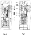
- FIG. 1 shows a clamping and / or braking device whose Reibgehemme (121, 131), see. FIG. 5 , Is actuated by means of a drive.
- the device engages with its c-shaped main body (10) a guide rail (7).
- main body (10) or in the housing are located between an adaptable - not shown here - drive device and the Reibgehemme (121, 131) two successively connected splined gearing (70, 100).
- the sliding splines (70, 100) are mechanically secured in a clamped and unclamped position by means of a latching mechanism (50) in the form of a bistable form-locking mechanism.
- a drive device on the base body (10) has this near its rear end wall, for example, a fine thread (26).
- the housing (10) is in FIG. 1 without a lid (37), cf. FIG. 12 , shown to show the arrangement of Reibgesperres.
- the guide rail (7) consists of a rod with an approximately cuboid envelope cross-section, in each of which a substantially V-shaped groove with a widened groove base is incorporated on both sides.
- the guide rail (7) contacts via its bottom surface e.g. the machine bed (5) carrying it.
- the guide rail (7) has u.a. above the V-shaped groove.
- two secondary surfaces (8, 9) which - in relation to the vertical center longitudinal plane (6) - are mirror images of each other.
- Both auxiliary surfaces (8, 9) are aligned parallel to each other. They serve the friction jaws (122, 132) as contact surfaces.
- the right friction pad (132) that is, which lies in the housing zone (11), also be omitted.
- the housing (10) has a right (11) and a left housing zone (12). Both zones (11, 12) are located below a flange zone (13).
- a plate-shaped, large-area device carrier (40) is mounted, see. FIGS. 1 and 11 , It consists of a rectangular or square plate, each having a threaded hole (44) for attachment to the machine slide (1) in the areas of their corners.
- a through hole (41) is incorporated with a large cylinder counterbore (42) in which a disc (47) is placed, for example by means of a countersunk screw (48) on the housing (10) is attached.
- a smaller cylinder counterbore (43) for receiving a ring-shaped or torus-shaped elastomeric body (49) is arranged.
- the device carrier (40) has in the recess (46) in the clamping direction (3) a play of e.g. 2 mm. In game longitudinal direction (2), the game is just so large that the device carrier (40) in the clamping direction (3) can still move without terminals.
- the elastomer body (49) arranged between the device carrier (40) and the housing (10) presses the device carrier (40) with the plane base of the cylinder depression (42) against the likewise flat underside of the disk (47) so that the device carrier (40) about 0.1 to 0.5 mm beyond the level of the top of the housing (10) protrudes.
- the Gehemmebohrung (31) has next to the Käfiglagerausappelung (35) has three stepped areas, see. FIG. 5 , From the outside of the housing, these are a main bore (32), a pressure piece guide bore (33) and an outlet bore (34).
- the main bore (32) opens into the - in the guide longitudinal direction - wider Käfiglagerausappelung (35). In its fine thread sits acting as a support element Einschraubdeckel (85).
- the biasing pressure piece (81) is mounted. It has the shape of a cylindrical piston with molded piston rod. The piston rod protrudes from the outlet bore (34) when the friction clip (121) is actuated. At the transition of the piston rod to the piston there is a circumferential end groove in which an elastic remindhubring (83) sits with eg rectangular single cross-section.
- the elastic remindhubring (83) is supported on a located between the pressure piece guide bore (33) and the outlet bore (34) housing collar.
- the skewed pressure piece (81) has a flattening in the lower region, against which a threaded pin (38) screwed into the housing (10) rests against rotation.
- the piston rod of the inclined pressure piece (81) at the same time forms a friction jaw (122) of the Reibgehemmes (121).
- a friction lining for example, a powder-metallurgically produced friction material is used bronze-based.
- the cylindrical surface bore (22) and the KäfiglagerausANSung (35) are additionally connected via a to the center line (29) parallel spring guide bore (27), cf. FIG. 5 , Furthermore, in this central housing region in the bottom surface of the cylinder surface bore (22) is another, likewise to the center line (29) parallel Vermosommesbohrung (36), see. FIG. 7 ,
- the main body (10) has a recess (16, 17) in its upper side.
- the upper region of the recess (16, 17) is a nearly rectangular recess (16) for receiving a lid (37), cf. FIG. 12 .
- the recess (16) merges into an at least approximately triangular recess (17), which intersects the cylindrical surface bore (22).
- the recess (17) surrounds a space in which a latching rocker moves as a coupling element (51) of the Formrichtgesperres (50).
- the first splined gearing (70) is arranged in the cage bearing recess (35) in the vicinity of the groove (19). It consists of the inclined pressure piece (81) and the follower wedge (71).
- the octagonal successive wedge (71), cf. FIGS. 2 and 3 lies with its wedge surface (72) on the skewed pressure piece (81).
- the wedge surface (72) of the follower wedge (71) and the wedge surface (82) of the skewed pressure piece (81) close with the guide longitudinal direction (2) an angle of 2.5 degrees.
- Said angle may be in a range of 2 to 10 degrees depending on the embodiment. This angular range ensures a self-locking between the sliding follower wedge (71) and the skewed pressure piece (81), provided that both components consist of a steel alloy and contact at least substantially dry.
- the follower wedge (71) has a rectangular cross-section which is uniaxial to the front face (74) and e.g. linearly tapered.
- the cage (110) which is part of a second sliding wedge gear (100), here is a chamber body, which consists of two equally shaped cylindrical sections formed against each other. Each cylinder section has the cross section of a circle section whose arc height is smaller than that of the circle radius. The bow height corresponds to eg approx. 83% of the circle radius.
- the imaginary, located between the cylinder sections, contact plane is referred to as cage center longitudinal plane.
- the cage (110) Parallel to the cage center longitudinal plane, the cage (110) has a passage (115) with an at least approximately rectangular cross-section.
- the passageway (115) is through the cage center longitudinal plane halved. In the two end portions of the passage channel (115) sit with play the cylindrical rollers (119).
- Transverse to the cage center longitudinal plane of the cage (110) has a Schiebekeilausnaturalung (116) with a likewise at least approximately rectangular cross-section.
- the one-sided in the cage (110) incorporated Schiebekeilausnaturalung (116) extends so far into the interior of the cage (110) that it penetrates the visible here side of the cage at two points in the form of two approximately rectangular window. Between the windows is a transverse bore (117), which is oriented normal to the cage center longitudinal plane and, for example, in the middle of the Schiebekeilaus Principleung (116). With a built-in cage (110), the transverse bore (117) is crossed by the push rod (106), cf. also FIGS. 12 and 13 ,
- the cage (110) has a front stop (111) on the side facing the follower wedge (71). On this side is also above and below the passage channel (115) each have a projecting guide web (113).
- the guide webs (113) guide the follower wedge (71).
- the drive wedge (101) has laterally two wedge surfaces (102, 103) which in each case enclose an angle of 0.4 to 1 angle with respect to a wedge-in direction (89). In the exemplary embodiment, the angle is 0.65 degrees.
- the drive wedge (101) has a rectangular cross section, the uniaxial direction (89) uniaxial and e.g. linearly tapered.
- the wedge-in direction (89) is that direction of displacement of the driving wedge in which a spreading action of the paired sliding wedges of a gearbox oriented transversely to the direction of displacement arises. It is in the embodiment of Figure 5 in almost all drive wedge positions not parallel to the guide longitudinal direction (2).
- the drive wedge (101) is at the front end of a e.g. cylindrical push rod (106) rigidly secured by a screw (107). Centered at the rear end of the push rod (106) is a disc-shaped, circular plate (108) by means of the countersunk screw (109). This push rod (106) forms the movable between two end positions output member of the device.
- the plate is guided spring-loaded in a carriage (90).
- the carriage (90) is in turn mounted and guided in the cylindrical surface bore (22) of the base body (10).
- the carriage (90) is essentially a pot-shaped component, which has at least partially a cylindrical outer contour.
- the outer contour has a diameter of eg 20 mm.
- the shortest distance between the center line (29) and the flattening (92) is 8 mm.
- the carriage (90) has a central through stepped bore (93-95).
- the front portion of the stepped bore is an aperture portion (93), the middle portion is a cylindrical guide portion (94), and the rear portion is a female threaded cover bearing portion (95).
- the guide portion (94) has a diameter of e.g. 10.6 mm.
- the plate (108) is led.
- a lid (96) is screwed.
- the helical compression springs (99), as well as the helical compression springs (98) located in front of the slide (90), can have opposite slopes.
- the spring force of the system of parallel spring elements (99) is greater than the spring force of the system of the parallel spring elements (98) at each stroke.
- a drive device acting on the drive wedge (101) shifts the carriage (90) forward and upon release in the opposite direction for braking, clamping or gripping.
- the drive device sliding the carriage (90) in the drive direction (4) tensions the at least slightly preloaded helical compression springs (98).
- the latter form here a spring accumulator whose energy is required again when releasing the brake, clamping or gripping device.
- the push rod (106) or the plate (108) in the longitudinal direction of leadership unyielding be articulated.
- the drive device can also act directly on the push rod (106).
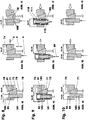
- FIGS. 8 to 10 For example, three types of interaction of two sliding wedge gears (70, 100) are shown schematically.
- the wedge angle of these splined wedge gears are for optical function clarification compared to in the FIGS. 1 to 4 and 11 to 15 chosen variant very large. That in the FIGS. 1 to 4 and 11 to 15 described functional principle corresponds in the schematic representations of FIG. 9 ,
- Fig. A consists of a first splined gearing (70) of a guided in a housing (10) inclined pressure piece (81) and a follower wedge (71).
- the biasing pressure piece (81) is part of the Reibgehemmes (121). It is in the clamped device on the guide rail (7), see. also FIG. 5 .
- the follower wedge (71), which rests with its right wedge surface (72) on the skewed pressure piece (81), is supported on the housing (10) via a spring element (78), here for example a helical compression spring. His also designed as a wedge surface (73) back and its end face (74) are at least partially on a drive wedge (101).
- the wedge surfaces (72, 82) are inclined by 20 degrees with respect to the guide longitudinal direction (2) of the drive wedge (101) in the same direction.
- the left wedge surface (73) of the follower wedge (71) contacts the wedge surface (102) of the drive wedge (101).
- Both wedge surfaces (73, 102) are inclined in the same direction relative to the guide longitudinal direction (2).
- the wedge angle is here eg 5 degrees.
- the drive wedge (101) has a front stop (104).
- the drive wedge (101) is part of the second spline transmission (100), which is also a Gleitschiebekeilgetriebe.
- the latter has, in addition to the drive wedge (101), a support element (85).
- the support member (85) is fixed to the housing (10). Possibly. it is also an integral part of the housing (10).
- the drive wedge (101) and the support element (85) make direct contact via plane surfaces, which are oriented parallel to the guide longitudinal direction (2).
- the splines (70, 100) are in a rear, unactuated position.
- the skewed pressure piece (81) is not extended for clamping, braking or grasping.
- the latter pushes the inclined pressure piece (81) against the guide rail (7), cf. FIG. 6 .
- the oblique pressure piece (81) touches the guide rail (7) possibly even slightly shifts it to the right until the guide rail (7) is gripped in the housing (10), for example, almost without play, the static friction between the skewed pressure piece (81 ) and the follower wedge (71) so large that the follower wedge (71) no longer moves in the wedge direction (89).
- the spread width of the first slide wedge gear (70) has, for example, after FIG. 8 increased from 32.65 unit lengths to 34.47 unit lengths.
- the drive wedge (101) is supported by roller bearings between the follower wedge (71) and the support element (85), cf. also FIGS. 5 to 6 ,
- the drive wedge (101) is surrounded at least partially by a cage (110) leading, for example, two cylindrical rollers (119).
- the follower wedge (71) has a rear side (73) which is aligned parallel to the support side of the support element (85).
- the drive wedge (101) has a right (102) and a left wedge surface (103).
- Each of the wedge surfaces (102, 103) is opposite the guide longitudinal direction (2), e.g. tilted by 2.5 angles alternatingly. They thus include a wedge angle of 85 degrees, the peak in the drive direction (4) in front of the drive wedge (101).
- the cage (110) has at least two stops (111, 112) acting in opposite directions.
- the front stop (111) is comparable to the stop (104) of the drive wedge (101) FIG. 8 .
- the rear stop (112) lies behind FIG. 9 , Fig. A) and b), for example, on the back of the drive wedge (101) in order to be able to retract the follower wedge (71) by means of the front stop (111) of the cage (110) when returning the drive wedge (101).
- the drive wedge (101) rolls 10 unit lengths in the drive direction (4) to change the spread width of this second slide wedge gear (100) from 26.48 to 26.91 unit lengths.
- the cage (110) has moved forward by only 5 unit lengths.
- the drive wedge (101) has thereby released from the rear stop (112) of the cage (110).
- the FIG. 10 shows two splines (70, 100), in which the wedges (71, 101) of both wedge pairs slide along each other.
- the first splined gearing (70) here corresponds to the splines after FIG. 9 .
- the drive wedge (101) abuts on a following surface (102) on the follower wedge (71), which is oriented parallel to the guide longitudinal direction (2). It contacts the support element (85) via a wedge surface (103), wherein the wedge surface (86) of the support element (85) and that of the drive wedge (101) are inclined in the same direction at the same angle, eg 5 angular degrees.
- the peculiarity here is that already during the first displacement of the drive wedge (101) by the second splined gearing (100) results in a delivery in the clamping direction movement. While the first splined gearing (70) changes its spreading width from 30.46 to 32.28 unit lengths, cf. also FIG. 5 , the spread width increases from 19.54 to 19.98 unit lengths at the first shift, and from 19.98 to 20.42 unit lengths at the second shift when the second splined gear (100) is moved as a block.
- a cage with two or more cylindrical rollers or balls may be arranged.
- the bistable Formrichtgesperre (50) comprises, in addition to the housing (10) and the carriage (90), a latching track (69) arranged on the carriage (90) and a latching rocker (51) which is supported on the housing (10) and whose oscillating end is in or on the latching track (69). is guided.
- the latching rocker (51) is essentially a rod with a rectangular cross-section. It has a hole in each end area and in the middle area. In the front end region is the pivot hole (53) in which the latching rocker (51) rotates about a pivot pin (53).
- the pivot pin (54) is fixed in the base body (10) in a bore by means of a transverse press fit, see. FIGS. 12 and 13 ,
- the center line of the pivot pin (54) is the imaginary pivot axis (52) which intersects perpendicularly the center line (29).
- a guide pin (56) is pressed. The latter protrudes down from the latching rocker (51) out.
- a ball pressure piece (58) is pressed into the third hole. From the ball pressure piece (58) protrudes above a ball, the spring-loaded with mounted device on the underside of the lid (37). The ball pressure piece (58) frictionally fixes any position of the locking rocker (51) relative to the cover (37).
- the center lines of all three bores of the latching rocker (51) are e.g. in a plane.
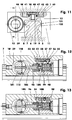
- FIG. 16 a perspective top view of a clamping device is shown, in which the lid (37), cf. FIG. 12 , is omitted.
- the lid (37), cf. FIG. 12 is omitted.
- a pass pin-like cross slide (151) is arranged transversely to the guide longitudinal direction displaceable.
- the cross slide (151) carries eg centrally the guide pin (56), which engages in the gate channel (60) of the carriage (90).
- the detent track (69) in the form of a slide channel (60) in the flattening (92) of the carriage (90) is incorporated, see. FIGS. 2, 3 . 14 and 15 .
- the slide channel (60) for example, has a rectangular cross-section, the guide pin (56) protrudes with at least 2 mm deep side with some side play.
- the center line (57) of the guide pin (56) describes the detent track (69) within the gate channel (60).
- the detent track (69) represents a closed curve, which has several points of discontinuity, cf. FIGS. 14 and 15 ,
- the gate channel (60) which consists largely of a clamping channel (61) and a release channel (62), there are two long-term holding positions (63, 64) and two short-term holding positions (65, 66).
- the first long-term holding position (63) is the position in which the guide pin (56) after FIG. 2 located. Its center is 1.6 mm to the right, offset from the midline (29).
- the spring elements (98) hold here the carriage (90) with unactuated device in its rear position. Now, if the carriage (90) by means of the drive device to the front, ie in the drive direction (4) moves, slides the guide pin (56) in the clamping channel (61) - right of the center line (29) - between an inner and an outer edge of the slide channel (60), to the rear until it blocks after, for example, about 10 mm stroke in the first short-term position (65).
- the inner flank is that flank which delimits the region of the flattening (92) which is enclosed by the sliding channel (60).
- the actuated drive device advances the carriage (90) in the drive direction (4) so far that the guide pin (56) abuts against a deflecting flank (68) to move at an angle of e.g. 19 angular degrees to the left in the second short-term holding position (66) to be pushed.
- the center of the second short-term holding position (66) lies - measured in the longitudinal direction of the guide - e.g. 0.7 mm behind the center of the second long-term holding position (64).
- the spring elements (98) push the carriage (90) backwards, whereby the guide pin (56) is deflected out of the short-term holding position (66) by the inner flank of the slide channel (60) forcibly to the left of the center line (FIG. 29) enters the release channel (62).
- the guide pin (56) slides back into the first long-term holding position (63).
- the carriage (90) performs a lifting movement, cf. FIG. 13 , although the Reibgehemme (121, 131) firmly against the guide rail (7).
- the drive wedge (101) can thus not move in the wedge direction (89). Consequently, the bottom (96) of the carriage (90) lifts off the plate (108) during the stroke between the second long-term holding position (64) and the second short-term holding position (66) against the action of the spring elements (99).
- FIG. 15 an alternative gate channel (60) is shown.
- the gate channel is aligned on the flat (92) so that the long-term holding points (63) and (64) and the pivot axis (52) of the pivot pin (54) lie in the plane in which also the center line (29) is arranged.
- the clamping channel (61) and the release channel (62) in each case in the plane of the flat (92) are curved in an S-shape. This curvature allows the guide pin (56), from the first long-term holding position (63) to thread smoothly into the clamping channel (61) on a continuous detent path section. The same applies to the guide pin (56) when being threaded into the release channel (62) out of the second short-term holding position (66).
- the required for the release feed movement of the drive device has a shorter stroke than necessary for the clamping feed movement.
- the individual splined gearing can also be arranged obliquely or transversely with respect to the guide longitudinal direction.
Landscapes
- Engineering & Computer Science (AREA)
- General Engineering & Computer Science (AREA)
- Mechanical Engineering (AREA)
- Transmission Devices (AREA)
- Manipulator (AREA)
- Bearings For Parts Moving Linearly (AREA)
Claims (10)
- Dispositif dans lequel un élément de sortie (106) monté de manière mobile présente deux positions extrêmes, dans lequel, entre l'élément de sortie (106) et son dispositif d'entraînement, est disposé un mécanisme d'encliquetage (50) au moyen duquel, lors d'une première impulsion d'entraînement, l'élément de sortie (106) peut être déplacé de la première position extrême à la deuxième position extrême par un mouvement de levage ou de pivotement à l'encontre d'une force de rappel, et au moyen duquel, lors d'une deuxième impulsion d'entraînement, l'élément de sortie (106) peut être transféré de la deuxième position extrême à la première position extrême par la force de rappel, caractérisé en ce- que le mécanisme d'encliquetage (50) disposé dans un boîtier (10) présente un chariot (90) qui peut être actionné par le dispositif d'entraînement et qui est en appui sur le boîtier (10) dans la direction d'action (4) de l'élément de sortie (106) au moyen d'un élément ou d'un système à ressort (98),- que l'élément de sortie (106) est disposé de manière coulissante ou pivotante dans ou sur le chariot (90),- que l'élément de sortie (106), sous la contrainte d'un ressort dans sa direction d'action (4), est en appui sur le chariot (90),- que le chariot (90) est couplé au boîtier (10) au moyen d'un élément de couplage (51, 151) faisant partie du mécanisme d'encliquetage (50),- que l'élément de couplage (51, 151) est monté sur le chariot (90) et guidé sur ou dans le boîtier (10) le long d'une glissière d'enclenchement (69) ou que l'élément de couplage (51, 151) et monté sur le chariot (90) et guidé sur le boîtier (10) le long d'une glissière d'enclenchement (69).
- Dispositif selon la revendication 1, caractérisé en ce que l'élément de sortie (106) est guidé dans le chariot (90) au moyen d'un plateau (108), ledit plateau (108), lorsque le dispositif n'est pas activé, étant en appui sur le chariot (90) dans la direction d'action (4) au moyen d'un élément ou d'un système à ressort (99).
- Dispositif selon la revendication 2, caractérisé en ce que l'élément ou le système à ressort (99) qui sollicite le plateau (108) présente au total une raideur plus grande qu'un élément ou système à ressort (98) qui soutient le chariot (90) sur le boîtier (10) dans la direction opposée à la direction d'action (4).
- Dispositif selon la revendication 1, caractérisé en ce que le système à ressort (98) et/ou le système à ressort (99) sont composés de ressorts hélicoïdaux de compression ou de traction emboîtés l'un dans l'autre ou disposés côte à côte, de rondelles ressorts empilées dans le même sens ou dans un sens opposé, d'un ressort à pression de gaz, d'un ressort en élastomère ou d'une combinaison des éléments à ressort mentionnés ci-devant.
- Dispositif selon la revendication 1, caractérisé en ce que la glissière d'enclenchement (69) est agencée sur le contour extérieur (91) du chariot (90).
- Dispositif selon la revendication 1, caractérisé en ce que la glissière d'enclenchement (69) est intégrée comme canal à coulisse (60) dans un aplatissement (92) du contour extérieur (91) du chariot (90) dans lequel un tourillon de guidage (56) disposé sur l'élément de couplage (51, 151) est engagé.
- Dispositif selon la revendication 1, caractérisé en ce que la glissière d'enclenchement (69) constitue une boucle fermée qui présente deux positions de retenue longue durée (63, 64) et deux positions de retenue courte durée (65, 66) .
- Dispositif selon la revendication 7, caractérisé en ce que les positions de retenue longue durée (63, 64) déterminent les positions sur la glissière d'enclenchement (69) où l'élément de couplage (51, 151) et le tourillon de guidage (56) maintiennent le chariot (90) dans une position de repos avant et dans une position de repos arrière.
- Dispositif selon la revendication 1, caractérisé en ce que le chariot (90) dans sa position de repos avant, l'élément d'entraînement ayant rempli sa fonction d'entraînement, présente, dans sa direction d'action (4) jusqu'à l'extrémité de guidage, une course résiduelle qui correspond au moins à la distance qui, mesurée dans la direction d'action, se situe entre le point central de la position de retenue arrière longue durée (64) et le point central de la deuxième position de retenue courte durée (66) .
- Dispositif selon la revendication 1, caractérisé en ce que le chariot (90) est guidé dans le boîtier (10) sans possibilité de rotation.
Applications Claiming Priority (2)
| Application Number | Priority Date | Filing Date | Title |
|---|---|---|---|
| DE102010045108A DE102010045108A1 (de) | 2010-09-13 | 2010-09-13 | Vorrichtung mit einer Rastmechanik |
| PCT/DE2011/001793 WO2012062260A2 (fr) | 2010-09-13 | 2011-09-13 | Appareil comportant une mécanique d'encliquetage |
Publications (2)
| Publication Number | Publication Date |
|---|---|
| EP2673523A2 EP2673523A2 (fr) | 2013-12-18 |
| EP2673523B1 true EP2673523B1 (fr) | 2019-04-24 |
Family
ID=45540687
Family Applications (1)
| Application Number | Title | Priority Date | Filing Date |
|---|---|---|---|
| EP11813661.3A Active EP2673523B1 (fr) | 2010-09-13 | 2011-09-13 | Appareil comportant une mécanique d'encliquetage |
Country Status (3)
| Country | Link |
|---|---|
| EP (1) | EP2673523B1 (fr) |
| DE (1) | DE102010045108A1 (fr) |
| WO (1) | WO2012062260A2 (fr) |
Families Citing this family (4)
| Publication number | Priority date | Publication date | Assignee | Title |
|---|---|---|---|---|
| DE102011115366A1 (de) | 2011-10-10 | 2013-04-11 | Günther Zimmer | Greifvorrichtung mit Haltevorrichtung |
| DE102013009780A1 (de) * | 2013-06-12 | 2014-12-18 | Günther Zimmer | Brems- und/ oder Klemmvorrichtung mit in der Kolbenstange integriertem Käfig |
| DE102013009779A1 (de) * | 2013-06-12 | 2014-12-18 | Günther Zimmer | Brems- und/ oder Klemmvorrichtung mit schräg angeordneter Abrollzone |
| DE102017220519A1 (de) * | 2017-11-16 | 2019-05-16 | Continental Automotive Gmbh | Steuerelement für Pedalsystem und Pedalsystem |
Family Cites Families (6)
| Publication number | Priority date | Publication date | Assignee | Title |
|---|---|---|---|---|
| DE1191645B (de) * | 1960-08-22 | 1965-08-22 | Parker Hannifin Corp | Steuerung fuer hydraulische Antriebe mit einem Steuerventil oder -schieber mit einer Arretierung |
| DE3925771A1 (de) * | 1989-08-03 | 1991-02-07 | Rexroth Mannesmann Gmbh | Wegeventil mit mehreren schaltstellungen |
| DE19908904C1 (de) * | 1999-03-02 | 2000-11-09 | Daimler Chrysler Ag | Fahrzeugbremse |
| AT412433B (de) * | 2000-05-11 | 2005-02-25 | Felten & Guilleaume Kg | Elektromechanischer fernschalter |
| DE10252915B3 (de) * | 2002-11-12 | 2004-04-08 | Zimmer GmbH, Technische Werkstätten | Reibgehemme mit Notbremsfunktion |
| DE102007005142B4 (de) * | 2007-02-01 | 2008-11-20 | Heckler & Koch Gmbh | Anschlussstück |
-
2010
- 2010-09-13 DE DE102010045108A patent/DE102010045108A1/de not_active Withdrawn
-
2011
- 2011-09-13 EP EP11813661.3A patent/EP2673523B1/fr active Active
- 2011-09-13 WO PCT/DE2011/001793 patent/WO2012062260A2/fr active Application Filing
Non-Patent Citations (1)
| Title |
|---|
| None * |
Also Published As
| Publication number | Publication date |
|---|---|
| WO2012062260A3 (fr) | 2013-11-14 |
| DE102010045108A1 (de) | 2012-03-15 |
| WO2012062260A2 (fr) | 2012-05-18 |
| EP2673523A2 (fr) | 2013-12-18 |
Similar Documents
| Publication | Publication Date | Title |
|---|---|---|
| EP2396141B1 (fr) | Dispositif d'arrêt à friction avec cage transversale | |
| DE3716202C2 (de) | Scheibenbremse für Fahrzeuge | |
| DE10252915B3 (de) | Reibgehemme mit Notbremsfunktion | |
| EP2395256B1 (fr) | Dispositif doté d'une soupape de mise en circuit | |
| DE102010018183A1 (de) | Vorrichtung mit verschiedenen Getrieben und Funktionsablauf der Vorrichtung | |
| EP2673523B1 (fr) | Appareil comportant une mécanique d'encliquetage | |
| DE102006062295B4 (de) | Klemmvorrichtung mit mindestens einem umgreifenden Klemmelement | |
| EP2813722B1 (fr) | Dispositif de serrage et/ou de freinage de chariot sur rail, doté d'une cage intégrée dans la tige de piston | |
| EP2616697B1 (fr) | Dispositif doté d'engrenages à clavette coulissante branchés les uns derrière les autres | |
| DE10207605C1 (de) | Reibgehemme mit Drillingskolbenentlastung | |
| EP1786593B1 (fr) | Dispositif de freinage et/ou de verrouillage comportant une transmission | |
| EP2813723B1 (fr) | Dispositif de freinage et/ou de blocage de chariot sur rail, à zone de roulement oblique | |
| EP2112396A1 (fr) | Dispositif de freinage et/ou de serrage pour arbres et rails de guidage | |
| EP2921260A1 (fr) | Appareil à entraînement pneumatique | |
| DE19957939C2 (de) | Elektromagnetisch betätigte Bremsvorrichtung | |
| EP0942190B1 (fr) | Dispositif de manoeuvre, en particulier pour un embrayage | |
| DE102007038789A1 (de) | Spannvorrichtung und Anordnung einer solchen Spannvorrichtung mit einer Spannzange | |
| EP0568858B1 (fr) | Dispositif de verrouillage d'un piston commandé par pression, en particulier pour la commande d'une barre antirenversement d'un véhicule | |
| DE102005029708B4 (de) | Brems- und/oder Klemmvorrichtung mit mindestens einem umgreifenden Bremselement | |
| DE1475400B2 (de) | Mechanische betaetigungsvorrichtung fuer eine hydraulisch zu betaetigende reibungsbremse, insbesondere teilbelagscheibenbremse fuer kraftfahrzeuge | |
| EP0152815B1 (fr) | Dispositif de rattrapage automatique pour cylindres de freins de véhicules | |
| EP1284172A1 (fr) | Dispositif de fixation pour une unité de mouvement linéaire | |
| DE2366135B1 (de) | Spreizkeil-Betaetigungsvorrichtung fuer Innenbackenbremsen | |
| DE19841189A1 (de) | Einrichtung zum Anpassen eines Koppelgetriebes | |
| DE2306523B2 (de) | Selbsttätige, mechanische Nachstellvorrichtung für Innenbackenbremsen |
Legal Events
| Date | Code | Title | Description |
|---|---|---|---|
| PUAI | Public reference made under article 153(3) epc to a published international application that has entered the european phase |
Free format text: ORIGINAL CODE: 0009012 |
|
| 17P | Request for examination filed |
Effective date: 20130409 |
|
| AK | Designated contracting states |
Kind code of ref document: A2 Designated state(s): AL AT BE BG CH CY CZ DE DK EE ES FI FR GB GR HR HU IE IS IT LI LT LU LV MC MK MT NL NO PL PT RO RS SE SI SK SM TR |
|
| GRAP | Despatch of communication of intention to grant a patent |
Free format text: ORIGINAL CODE: EPIDOSNIGR1 |
|
| STAA | Information on the status of an ep patent application or granted ep patent |
Free format text: STATUS: GRANT OF PATENT IS INTENDED |
|
| INTG | Intention to grant announced |
Effective date: 20181122 |
|
| GRAS | Grant fee paid |
Free format text: ORIGINAL CODE: EPIDOSNIGR3 |
|
| GRAA | (expected) grant |
Free format text: ORIGINAL CODE: 0009210 |
|
| STAA | Information on the status of an ep patent application or granted ep patent |
Free format text: STATUS: THE PATENT HAS BEEN GRANTED |
|
| AK | Designated contracting states |
Kind code of ref document: B1 Designated state(s): AL AT BE BG CH CY CZ DE DK EE ES FI FR GB GR HR HU IE IS IT LI LT LU LV MC MK MT NL NO PL PT RO RS SE SI SK SM TR |
|
| REG | Reference to a national code |
Ref country code: GB Ref legal event code: FG4D Free format text: NOT ENGLISH |
|
| REG | Reference to a national code |
Ref country code: CH Ref legal event code: EP |
|
| REG | Reference to a national code |
Ref country code: DE Ref legal event code: R096 Ref document number: 502011015634 Country of ref document: DE |
|
| REG | Reference to a national code |
Ref country code: AT Ref legal event code: REF Ref document number: 1124505 Country of ref document: AT Kind code of ref document: T Effective date: 20190515 Ref country code: IE Ref legal event code: FG4D Free format text: LANGUAGE OF EP DOCUMENT: GERMAN |
|
| REG | Reference to a national code |
Ref country code: NL Ref legal event code: MP Effective date: 20190424 |
|
| REG | Reference to a national code |
Ref country code: LT Ref legal event code: MG4D |
|
| PG25 | Lapsed in a contracting state [announced via postgrant information from national office to epo] |
Ref country code: NL Free format text: LAPSE BECAUSE OF FAILURE TO SUBMIT A TRANSLATION OF THE DESCRIPTION OR TO PAY THE FEE WITHIN THE PRESCRIBED TIME-LIMIT Effective date: 20190424 |
|
| PG25 | Lapsed in a contracting state [announced via postgrant information from national office to epo] |
Ref country code: ES Free format text: LAPSE BECAUSE OF FAILURE TO SUBMIT A TRANSLATION OF THE DESCRIPTION OR TO PAY THE FEE WITHIN THE PRESCRIBED TIME-LIMIT Effective date: 20190424 Ref country code: PT Free format text: LAPSE BECAUSE OF FAILURE TO SUBMIT A TRANSLATION OF THE DESCRIPTION OR TO PAY THE FEE WITHIN THE PRESCRIBED TIME-LIMIT Effective date: 20190824 Ref country code: SE Free format text: LAPSE BECAUSE OF FAILURE TO SUBMIT A TRANSLATION OF THE DESCRIPTION OR TO PAY THE FEE WITHIN THE PRESCRIBED TIME-LIMIT Effective date: 20190424 Ref country code: AL Free format text: LAPSE BECAUSE OF FAILURE TO SUBMIT A TRANSLATION OF THE DESCRIPTION OR TO PAY THE FEE WITHIN THE PRESCRIBED TIME-LIMIT Effective date: 20190424 Ref country code: LT Free format text: LAPSE BECAUSE OF FAILURE TO SUBMIT A TRANSLATION OF THE DESCRIPTION OR TO PAY THE FEE WITHIN THE PRESCRIBED TIME-LIMIT Effective date: 20190424 Ref country code: HR Free format text: LAPSE BECAUSE OF FAILURE TO SUBMIT A TRANSLATION OF THE DESCRIPTION OR TO PAY THE FEE WITHIN THE PRESCRIBED TIME-LIMIT Effective date: 20190424 Ref country code: NO Free format text: LAPSE BECAUSE OF FAILURE TO SUBMIT A TRANSLATION OF THE DESCRIPTION OR TO PAY THE FEE WITHIN THE PRESCRIBED TIME-LIMIT Effective date: 20190724 Ref country code: FI Free format text: LAPSE BECAUSE OF FAILURE TO SUBMIT A TRANSLATION OF THE DESCRIPTION OR TO PAY THE FEE WITHIN THE PRESCRIBED TIME-LIMIT Effective date: 20190424 |
|
| PG25 | Lapsed in a contracting state [announced via postgrant information from national office to epo] |
Ref country code: PL Free format text: LAPSE BECAUSE OF FAILURE TO SUBMIT A TRANSLATION OF THE DESCRIPTION OR TO PAY THE FEE WITHIN THE PRESCRIBED TIME-LIMIT Effective date: 20190424 Ref country code: GR Free format text: LAPSE BECAUSE OF FAILURE TO SUBMIT A TRANSLATION OF THE DESCRIPTION OR TO PAY THE FEE WITHIN THE PRESCRIBED TIME-LIMIT Effective date: 20190725 Ref country code: LV Free format text: LAPSE BECAUSE OF FAILURE TO SUBMIT A TRANSLATION OF THE DESCRIPTION OR TO PAY THE FEE WITHIN THE PRESCRIBED TIME-LIMIT Effective date: 20190424 Ref country code: BG Free format text: LAPSE BECAUSE OF FAILURE TO SUBMIT A TRANSLATION OF THE DESCRIPTION OR TO PAY THE FEE WITHIN THE PRESCRIBED TIME-LIMIT Effective date: 20190724 Ref country code: RS Free format text: LAPSE BECAUSE OF FAILURE TO SUBMIT A TRANSLATION OF THE DESCRIPTION OR TO PAY THE FEE WITHIN THE PRESCRIBED TIME-LIMIT Effective date: 20190424 |
|
| PG25 | Lapsed in a contracting state [announced via postgrant information from national office to epo] |
Ref country code: IS Free format text: LAPSE BECAUSE OF FAILURE TO SUBMIT A TRANSLATION OF THE DESCRIPTION OR TO PAY THE FEE WITHIN THE PRESCRIBED TIME-LIMIT Effective date: 20190824 |
|
| REG | Reference to a national code |
Ref country code: DE Ref legal event code: R097 Ref document number: 502011015634 Country of ref document: DE |
|
| PG25 | Lapsed in a contracting state [announced via postgrant information from national office to epo] |
Ref country code: DK Free format text: LAPSE BECAUSE OF FAILURE TO SUBMIT A TRANSLATION OF THE DESCRIPTION OR TO PAY THE FEE WITHIN THE PRESCRIBED TIME-LIMIT Effective date: 20190424 Ref country code: SK Free format text: LAPSE BECAUSE OF FAILURE TO SUBMIT A TRANSLATION OF THE DESCRIPTION OR TO PAY THE FEE WITHIN THE PRESCRIBED TIME-LIMIT Effective date: 20190424 Ref country code: RO Free format text: LAPSE BECAUSE OF FAILURE TO SUBMIT A TRANSLATION OF THE DESCRIPTION OR TO PAY THE FEE WITHIN THE PRESCRIBED TIME-LIMIT Effective date: 20190424 Ref country code: EE Free format text: LAPSE BECAUSE OF FAILURE TO SUBMIT A TRANSLATION OF THE DESCRIPTION OR TO PAY THE FEE WITHIN THE PRESCRIBED TIME-LIMIT Effective date: 20190424 Ref country code: CZ Free format text: LAPSE BECAUSE OF FAILURE TO SUBMIT A TRANSLATION OF THE DESCRIPTION OR TO PAY THE FEE WITHIN THE PRESCRIBED TIME-LIMIT Effective date: 20190424 |
|
| PG25 | Lapsed in a contracting state [announced via postgrant information from national office to epo] |
Ref country code: SM Free format text: LAPSE BECAUSE OF FAILURE TO SUBMIT A TRANSLATION OF THE DESCRIPTION OR TO PAY THE FEE WITHIN THE PRESCRIBED TIME-LIMIT Effective date: 20190424 |
|
| PLBE | No opposition filed within time limit |
Free format text: ORIGINAL CODE: 0009261 |
|
| STAA | Information on the status of an ep patent application or granted ep patent |
Free format text: STATUS: NO OPPOSITION FILED WITHIN TIME LIMIT |
|
| PG25 | Lapsed in a contracting state [announced via postgrant information from national office to epo] |
Ref country code: TR Free format text: LAPSE BECAUSE OF FAILURE TO SUBMIT A TRANSLATION OF THE DESCRIPTION OR TO PAY THE FEE WITHIN THE PRESCRIBED TIME-LIMIT Effective date: 20190424 |
|
| 26N | No opposition filed |
Effective date: 20200127 |
|
| PG25 | Lapsed in a contracting state [announced via postgrant information from national office to epo] |
Ref country code: SI Free format text: LAPSE BECAUSE OF FAILURE TO SUBMIT A TRANSLATION OF THE DESCRIPTION OR TO PAY THE FEE WITHIN THE PRESCRIBED TIME-LIMIT Effective date: 20190424 Ref country code: MC Free format text: LAPSE BECAUSE OF FAILURE TO SUBMIT A TRANSLATION OF THE DESCRIPTION OR TO PAY THE FEE WITHIN THE PRESCRIBED TIME-LIMIT Effective date: 20190424 |
|
| REG | Reference to a national code |
Ref country code: CH Ref legal event code: PL |
|
| PG25 | Lapsed in a contracting state [announced via postgrant information from national office to epo] |
Ref country code: CH Free format text: LAPSE BECAUSE OF NON-PAYMENT OF DUE FEES Effective date: 20190930 Ref country code: LU Free format text: LAPSE BECAUSE OF NON-PAYMENT OF DUE FEES Effective date: 20190913 Ref country code: IE Free format text: LAPSE BECAUSE OF NON-PAYMENT OF DUE FEES Effective date: 20190913 Ref country code: LI Free format text: LAPSE BECAUSE OF NON-PAYMENT OF DUE FEES Effective date: 20190930 |
|
| REG | Reference to a national code |
Ref country code: BE Ref legal event code: MM Effective date: 20190930 |
|
| PG25 | Lapsed in a contracting state [announced via postgrant information from national office to epo] |
Ref country code: BE Free format text: LAPSE BECAUSE OF NON-PAYMENT OF DUE FEES Effective date: 20190930 |
|
| GBPC | Gb: european patent ceased through non-payment of renewal fee |
Effective date: 20190913 |
|
| REG | Reference to a national code |
Ref country code: GB Ref legal event code: S28 Free format text: APPLICATION FILED |
|
| PG25 | Lapsed in a contracting state [announced via postgrant information from national office to epo] |
Ref country code: GB Free format text: LAPSE BECAUSE OF NON-PAYMENT OF DUE FEES Effective date: 20190913 |
|
| REG | Reference to a national code |
Ref country code: AT Ref legal event code: MM01 Ref document number: 1124505 Country of ref document: AT Kind code of ref document: T Effective date: 20190913 |
|
| REG | Reference to a national code |
Ref country code: GB Ref legal event code: S28 Free format text: RESTORATION ALLOWED Effective date: 20201029 |
|
| PG25 | Lapsed in a contracting state [announced via postgrant information from national office to epo] |
Ref country code: AT Free format text: LAPSE BECAUSE OF NON-PAYMENT OF DUE FEES Effective date: 20190913 |
|
| PG25 | Lapsed in a contracting state [announced via postgrant information from national office to epo] |
Ref country code: CY Free format text: LAPSE BECAUSE OF FAILURE TO SUBMIT A TRANSLATION OF THE DESCRIPTION OR TO PAY THE FEE WITHIN THE PRESCRIBED TIME-LIMIT Effective date: 20190424 |
|
| PG25 | Lapsed in a contracting state [announced via postgrant information from national office to epo] |
Ref country code: HU Free format text: LAPSE BECAUSE OF FAILURE TO SUBMIT A TRANSLATION OF THE DESCRIPTION OR TO PAY THE FEE WITHIN THE PRESCRIBED TIME-LIMIT; INVALID AB INITIO Effective date: 20110913 Ref country code: MT Free format text: LAPSE BECAUSE OF FAILURE TO SUBMIT A TRANSLATION OF THE DESCRIPTION OR TO PAY THE FEE WITHIN THE PRESCRIBED TIME-LIMIT Effective date: 20190424 |
|
| PG25 | Lapsed in a contracting state [announced via postgrant information from national office to epo] |
Ref country code: MK Free format text: LAPSE BECAUSE OF FAILURE TO SUBMIT A TRANSLATION OF THE DESCRIPTION OR TO PAY THE FEE WITHIN THE PRESCRIBED TIME-LIMIT Effective date: 20190424 |
|
| PGFP | Annual fee paid to national office [announced via postgrant information from national office to epo] |
Ref country code: GB Payment date: 20230920 Year of fee payment: 13 |
|
| PGFP | Annual fee paid to national office [announced via postgrant information from national office to epo] |
Ref country code: FR Payment date: 20230922 Year of fee payment: 13 Ref country code: DE Payment date: 20230928 Year of fee payment: 13 |
|
| PGFP | Annual fee paid to national office [announced via postgrant information from national office to epo] |
Ref country code: IT Payment date: 20230927 Year of fee payment: 13 |