EP2673428B1 - Precast wall panels and method of erecting a high-rise building using the panels - Google Patents
Precast wall panels and method of erecting a high-rise building using the panels Download PDFInfo
- Publication number
- EP2673428B1 EP2673428B1 EP12744820.7A EP12744820A EP2673428B1 EP 2673428 B1 EP2673428 B1 EP 2673428B1 EP 12744820 A EP12744820 A EP 12744820A EP 2673428 B1 EP2673428 B1 EP 2673428B1
- Authority
- EP
- European Patent Office
- Prior art keywords
- precast
- panel
- panels
- precast panel
- wall system
- Prior art date
- Legal status (The legal status is an assumption and is not a legal conclusion. Google has not performed a legal analysis and makes no representation as to the accuracy of the status listed.)
- Active
Links
Images



















Classifications
-
- E—FIXED CONSTRUCTIONS
- E04—BUILDING
- E04B—GENERAL BUILDING CONSTRUCTIONS; WALLS, e.g. PARTITIONS; ROOFS; FLOORS; CEILINGS; INSULATION OR OTHER PROTECTION OF BUILDINGS
- E04B2/00—Walls, e.g. partitions, for buildings; Wall construction with regard to insulation; Connections specially adapted to walls
- E04B2/56—Load-bearing walls of framework or pillarwork; Walls incorporating load-bearing elongated members
- E04B2/64—Load-bearing walls of framework or pillarwork; Walls incorporating load-bearing elongated members with elongated members of concrete
-
- E—FIXED CONSTRUCTIONS
- E04—BUILDING
- E04B—GENERAL BUILDING CONSTRUCTIONS; WALLS, e.g. PARTITIONS; ROOFS; FLOORS; CEILINGS; INSULATION OR OTHER PROTECTION OF BUILDINGS
- E04B1/00—Constructions in general; Structures which are not restricted either to walls, e.g. partitions, or floors or ceilings or roofs
- E04B1/02—Structures consisting primarily of load-supporting, block-shaped, or slab-shaped elements
- E04B1/04—Structures consisting primarily of load-supporting, block-shaped, or slab-shaped elements the elements consisting of concrete, e.g. reinforced concrete, or other stone-like material
-
- E—FIXED CONSTRUCTIONS
- E04—BUILDING
- E04B—GENERAL BUILDING CONSTRUCTIONS; WALLS, e.g. PARTITIONS; ROOFS; FLOORS; CEILINGS; INSULATION OR OTHER PROTECTION OF BUILDINGS
- E04B1/00—Constructions in general; Structures which are not restricted either to walls, e.g. partitions, or floors or ceilings or roofs
- E04B1/18—Structures comprising elongated load-supporting parts, e.g. columns, girders, skeletons
- E04B1/24—Structures comprising elongated load-supporting parts, e.g. columns, girders, skeletons the supporting parts consisting of metal
-
- E—FIXED CONSTRUCTIONS
- E04—BUILDING
- E04B—GENERAL BUILDING CONSTRUCTIONS; WALLS, e.g. PARTITIONS; ROOFS; FLOORS; CEILINGS; INSULATION OR OTHER PROTECTION OF BUILDINGS
- E04B1/00—Constructions in general; Structures which are not restricted either to walls, e.g. partitions, or floors or ceilings or roofs
- E04B1/34—Extraordinary structures, e.g. with suspended or cantilever parts supported by masts or tower-like structures enclosing elevators or stairs; Features relating to the elastic stability
-
- E—FIXED CONSTRUCTIONS
- E04—BUILDING
- E04C—STRUCTURAL ELEMENTS; BUILDING MATERIALS
- E04C2/00—Building elements of relatively thin form for the construction of parts of buildings, e.g. sheet materials, slabs, or panels
- E04C2/02—Building elements of relatively thin form for the construction of parts of buildings, e.g. sheet materials, slabs, or panels characterised by specified materials
- E04C2/04—Building elements of relatively thin form for the construction of parts of buildings, e.g. sheet materials, slabs, or panels characterised by specified materials of concrete or other stone-like material; of asbestos cement; of cement and other mineral fibres
- E04C2/06—Building elements of relatively thin form for the construction of parts of buildings, e.g. sheet materials, slabs, or panels characterised by specified materials of concrete or other stone-like material; of asbestos cement; of cement and other mineral fibres reinforced
-
- E—FIXED CONSTRUCTIONS
- E04—BUILDING
- E04G—SCAFFOLDING; FORMS; SHUTTERING; BUILDING IMPLEMENTS OR AIDS, OR THEIR USE; HANDLING BUILDING MATERIALS ON THE SITE; REPAIRING, BREAKING-UP OR OTHER WORK ON EXISTING BUILDINGS
- E04G21/00—Preparing, conveying, or working-up building materials or building elements in situ; Other devices or measures for constructional work
- E04G21/14—Conveying or assembling building elements
- E04G21/16—Tools or apparatus
-
- E—FIXED CONSTRUCTIONS
- E04—BUILDING
- E04G—SCAFFOLDING; FORMS; SHUTTERING; BUILDING IMPLEMENTS OR AIDS, OR THEIR USE; HANDLING BUILDING MATERIALS ON THE SITE; REPAIRING, BREAKING-UP OR OTHER WORK ON EXISTING BUILDINGS
- E04G21/00—Preparing, conveying, or working-up building materials or building elements in situ; Other devices or measures for constructional work
- E04G21/24—Safety or protective measures preventing damage to building parts or finishing work during construction
- E04G21/26—Strutting means for wall parts; Supports or the like, e.g. for holding in position prefabricated walls
-
- E—FIXED CONSTRUCTIONS
- E04—BUILDING
- E04B—GENERAL BUILDING CONSTRUCTIONS; WALLS, e.g. PARTITIONS; ROOFS; FLOORS; CEILINGS; INSULATION OR OTHER PROTECTION OF BUILDINGS
- E04B1/00—Constructions in general; Structures which are not restricted either to walls, e.g. partitions, or floors or ceilings or roofs
- E04B1/18—Structures comprising elongated load-supporting parts, e.g. columns, girders, skeletons
- E04B1/24—Structures comprising elongated load-supporting parts, e.g. columns, girders, skeletons the supporting parts consisting of metal
- E04B1/2403—Connection details of the elongated load-supporting parts
-
- E—FIXED CONSTRUCTIONS
- E04—BUILDING
- E04B—GENERAL BUILDING CONSTRUCTIONS; WALLS, e.g. PARTITIONS; ROOFS; FLOORS; CEILINGS; INSULATION OR OTHER PROTECTION OF BUILDINGS
- E04B1/00—Constructions in general; Structures which are not restricted either to walls, e.g. partitions, or floors or ceilings or roofs
- E04B1/18—Structures comprising elongated load-supporting parts, e.g. columns, girders, skeletons
- E04B1/24—Structures comprising elongated load-supporting parts, e.g. columns, girders, skeletons the supporting parts consisting of metal
- E04B1/2403—Connection details of the elongated load-supporting parts
- E04B2001/2415—Brackets, gussets, joining plates
-
- E—FIXED CONSTRUCTIONS
- E04—BUILDING
- E04B—GENERAL BUILDING CONSTRUCTIONS; WALLS, e.g. PARTITIONS; ROOFS; FLOORS; CEILINGS; INSULATION OR OTHER PROTECTION OF BUILDINGS
- E04B1/00—Constructions in general; Structures which are not restricted either to walls, e.g. partitions, or floors or ceilings or roofs
- E04B1/18—Structures comprising elongated load-supporting parts, e.g. columns, girders, skeletons
- E04B1/24—Structures comprising elongated load-supporting parts, e.g. columns, girders, skeletons the supporting parts consisting of metal
- E04B2001/2496—Shear bracing therefor
Definitions
- the present invention reflates to static building structures, and more particularly, to precast wall panels that may be interconnected to form a core or perimeter wall system for erecting or constructing a high-rise building or other walled structure.
- High-rise buildings typically are constructed to have six or more floors or stories above ground level.
- the design of a high-rise building is usually governed by wind effects.
- One of the most efficient structural systems to resist wind loads for a high-rise building is an interior or core wall system.
- Conventional core wall systems for high-rise buildings are typically constructed from concrete (cast-in-place over rebar cages for reinforcement) for each story of the high-rise building.
- conventional core wall systems incorporate structural steel columns and floor beams erected prior to the construction of then cast-in-place core walls.
- concrete is cast in place over the structural steel columns and floor beams.
- a concrete core wall system provides a number of benefits compared to a structural steel systems
- Concrete core walls have higher structural damping than structural steel systems, therefore reducing the amount of sway and drift due to wind loads.
- Concrete core walls provide increased safety and security for fire stairs, standpipes, and communications systems. Because of these reasons, following the events of September 11, 2001, there has been even more emphasis on the use of concrete core walls systems for erecting or constructing high-rise buildings.
- a column member interconnecting adjacent panels comprises column member portions from both panels.
- these conventional precast components, and structures built from such components lack sufficient strength to resist and transfer wind and gravity loads as present in core wall systems of a high-rise building.
- Precast wall panels that may be interconnected to form a core or perimeter wall system for erecting or to constructing a high-rise building or other walled structure.
- Precast core or perimeter wall systems (hereinafter a "precast wall system") consistent with the present invention offer an attractive alternative to cast-in-place concrete core systems.
- Precast wall panels as described herein may be prepared (using concrete or other cementitious material) in advance under controlled conditions providing improved quality control and an opportunity for pre-inspection, verification and correction before being shipped to the construction site, resulting in superior quality products.
- the precast wall panels also allow construction of a high-rise building even under difficult weather conditions.
- the construction speed possible with precast wall systems consistent with the present invention reduces construction schedule, minimizes on-site labor costs, and provides significant economy to the high-rise building project.
- a precast wall system comprises a plurality of interconnected precast panels.
- Each precast panel has a top end plate, a bottom end plate, a plurality of vertical bars disposed between and attached to the end plates (to effectively function as one means to transfer vertical loads), and cementitious material (such as concrete) encasing the vertical bars and defining a plurality of sides of the respective panel.
- a second plurality of the interconnected precast panels are arranged on and vertically adjacent to a first plurality of the interconnected precast panels and the top end plate of each panel corresponding the first plurality is connected to the bottom end plate of a respective one of the panels corresponding to the second plurality.
- Each of the interconnected precast panels may have a length corresponding to one or more stories of a building.
- the precast wall system may further comprise a panel-to-panel vertical reinforcing member, such as a vertical reinforcing bar or tensioning cable.
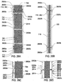
- a first of the first plurality of precast panels has a duct extending from the top end plate of the first panel towards the bottom plate of the first panel.
- the top end plate of the first panel has a opening extending through the top end plate and in axial alignment with the duct of the first panel.
- a second of the second plurality of precast panels also has a duct extending from the top end plate of the second panel to the bottom plate of the second panel.
- the two end plates of the second panel each has a opening extending through the respective plate and in axial alignment with the duct of the second panel.
- the vertical reinforcing member is disposed in and extends through the duct of the second panel, the opening of the bottom end plate of the second panel, the opening of the top end plate of the first panel and the duct of the first panel.
- a first of the precast panels has a first side plate affixed to a side of the first precast panel and a second of the precast panels has a second side plate affixed to aside of the second precast panel that is adjacent to the first precast panel.
- the first side plate of the first precast panel is affixed to the second side plate of the second precast panel.
- the precast wall system may include a panel-to-panel horizontal reinforcing member.., such as a vertical reinforcing bar or tensioning cable.
- a first of the first plurality of precast panels has a first duct extending through a first width of the first panel.
- a second of the second plurality of precast panels has a second duct extending through a second width of the second panel in axial alignment with the first duct of the first panel.
- the horizontal reinforcing member is disposed in and extends through the first duct of the panel and the second duct of the second panel.
- the precast wall system comprises a plurality of precast panels
- Each precast panel includes a cementitious material (such as reinforced concrete) and has a right side, a left side, a front side and a back side defining a plurality of corner edges extending a height of the respective precast panel.
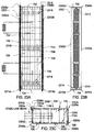
- Each precast panel further includes a plurality of structural angles. Each angle is disposed along a respective one of the corner edges of the precast panel Each angle has a first leg that extends along and is embedded in one of the right side or the left side of the panel and a second leg that extends along and is embedded in one of the front side or the back side of the respective panel.
- a first of the precast panels may be arranged vertically on a second of the precast panels and each structural angle of the first precast panel may then be affixed to a corresponding one of the structural angles of the second precast panel.
- each structural angle of the first precast panel may have a leg embedded on the right side of the first precast panel that is horizontally aligned with and affixed to a corresponding structural angle of another of the precast panels having a leg embedded on the left side of the other precast panel.
- the precast pane! comprises a cementitious material and has a top end, a bottom end, a front side and a back side.
- the precast panel further includes a first plurality of lifting lugs.
- Each lifting lug includes a body and a first end extending and curving away from the body.
- the body of each lifting lug is configured to be removably attached to one of the front side or back side of the precast panel.
- the first end of each lifting lug has an attachment point (such as an orifice) for a hoisting rig.
- the first plurality of lifting lugs are attached in proximity to and spaced about the top end of the precast panel so that the first end of each lifting lug extends beyond and curves away from the top end.
- the first end of each lifting lug curves away from the top end of the precast panel such that the first end of each lifting lug is effective to capture and guide another vertically adjacent precast panel towards the top end of the precast panel having the first plurality of lifting lugs.
- the precast panel having the first plurality of lifting lugs may also have a second plurality of lifting lugs attached in proximity to and spaced about the bottom end of the precast panel.
- each of the second plurality of lifting lugs extends beyond and curves away from the bottom end of the precast panel such that the first end of each of the second plurality of lifting lugs effectively captures a top end of another precast panel disposed below the precast panel having the second plurality of lifting lugs.
- the precast wall system comprises a plurality of horizontally interconnected precast panels.
- Each precast panel has a top end plate, a bottom end plate, a plurality of vertical bars disposed between the end plates and a comentitious material encasing the vertical bars and defining a plurality of sides of the respective panel.
- a first of the precast panels has a first column member half defining a right side of the first panel.
- a second of the precast panels has a second column member half defining a left side of the second panel.
- the column member has a strength to support a gravity column, providing transition between systems consistent with the present invention and systems with steel columns
- one of the first plurality of horizontally interconnected precast panels is a corner precast panel that includes a column member having an end partially encased in the corner precast panel and another end extending above the top of the corner precast panel.
- the column member has a strength to support a gravity column.
- the precast wall system comprises a transfer member; a connection plate; a second plurality of horizontally interconnected precast panels defining a lower tier; and a first plurality of interconnected precast panels arranged on and vertically adjacent to the second plurality of the interconnected precast panels to define an upper tier.
- Each precast panel has a top end plate, a bottom end plate, a plurality of vertical bars disposed between the end plates and a cementitious material encasing the vertical bars and defining a plurality of sides of the respective panel.
- the upper tier precast panels are thinner than the lower tier precast panels.
- Each precast panel has a plurality of corner edges extending a height of the precast panel and each precast panel further includes a plurality of structural angles. Each angle is disposed along a respective one of the corner edges of the precast panel.
- the transfer member has a width equal to a change of thickness ( ⁇ t) of the lower and upper tier precast panels. The transfer member is affixed to the structural angle or one of the upper tier precast panels and a portion of the bottom end plate extending from the one upper precast panel. The connection plate spans and is affixed to the transfer member and the structural angle of one of the lower precast panels vertically adjacent to the one upper precast panel.
- precast panels consistent with the present invention are pre-formed using a cementitious material such as concrete such that a large portion of the shrinkage of the concrete occurs during the early stages of curing (i.e., before the precast panel is placed or set in the building or structure). During this period, precast panels as disclosed herein have very little restraint at their edges and therefore develop less shrinkage stresses than comparable cast-in-place walls.
- the dimensional changes to the building are reduced particularly the differential movements between the core and perimeter columns.
- the precast panels are initially loaded (e.g., with an additional story structure for the building) after a later curing age than in cast-in-place construction, the effect of creep is also reduced by precast panels consistent with the present invention.
- Fig. 1 is a perspective view of an exemplary precast wall panel system 100 consistent with the present invention.
- the precast wall system 100 may be erected or constructed on a cast-in-place foundation 50 as shown in Figs. 2 and 3 , or on a standard cast-in-place wall system 60 as shown in Fig. 4 .
- the precast wall system 100 comprises multiple precast panels 102, 104, 106, 108 and 110 that may be interconnected horizontally and/or vertically to construct multiple core or perimeter walls of multiple stories of a high-rise building.
- pluralities or groups (112a, 112b and 112c) of the precast panels 102, 104, 106, 108 and 110 are interconnected horizontally or side-by-side to respectively define one or more stories of a building or core walls for the building.
- additional groups 112b and 112c of the precast panels 102, 104, 106, 108 and 110 may be arranged on and vertically interconnected to the lower group (e.g., 112a or 112c in Fig. 1 ) of precast panels 102, 104, 106, 108 and 110.
- each precast panel 102, 104, 106, 108 and 110 in each group 112a, 112b and 112c of precast panels has a length corresponding to two stories of a building such that the precast wall system 100 reflects a six story section.
- the length of each precast panel may vary between groups such that a first group 112a of panels may correspond to one story or more stories, and each succeeding group 112b and 112c may each correspond to the same number or a different number of stories of the building.
- the reference number of the precast panels 102, 104, 106, 108 and 110 is augmented with an "a" designator to indicate that the respective panel 102a, 104a, 106a, 108a or 110a is included in the first group or plurality 112a of precast panels, a "b" designator to indicate the respective panel 102b, 104b, 106b, 108b or 110b is included in the second group or plurality 112b of precast panels, or a "c" designator to indicate the respective panel 102c, 104c, 106c, 108c or 110c is included in the third group or plurality 112c of precast panels.
- the precast panels 102, 104, 106, 108 and 110 may correspond to one of three types of panels: an interior panel 102, a comer panel 104, and an opening panel 106, 108 and 110.
- Each interior panel 102 is disposed between two adjacent panels that may be two other interior panels 102, two corner panels 104, two opening panels 106, 108 or 110, or some combination thereof.
- Each interior panel 102 preferably has a horizontal rectangular cross-section. However, the interior panel 102 may have another cross-section shape, such as a bowed front side and/or back side.
- Corner panels 104 are also disposed between two adjacent panels (e.g., two interior panels 102 or two opening panels 106, 108 and 110).
- each corner panel 104 has a horizontal L-shaped cross-section, enabling walls of the precast wall system 100 to be erected with different orientations (like for example perpendicular walls as shown in Fig. 1 ).
- corner panels 104 may have a non-right angle shape with sides that define an interior angle that is greater than or less than 90" to interconnect core non-orthogonal walls of the precast wall system 100 with a shape that is not rectangular.
- opening panels 106, 108 and 110 have one or more link beams (or beam segments) 114 or 116 that define an opening or gap between the respective opening panel and an adjacent opening panel, where the opening or gap is sufficient to enable a person to pass, or for passage of mechanical, electrical, or plumbing systems.
- the different precast panels 102, 104, 106, 108 and 110 may be interconnected to each other via one or or the panel-to-panel vertical connections, horizontal panel-to-panel connections, and/or link beam connections discussed in detail herein.
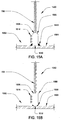
- Each precast panel 102, 104, 106, 108 and 110 has atop end plate (e.g, 702 in Figs. 7-10 , 1306 in Figs. 13A & 13B , 1406 in Figs. 14A-14E , and 702 in Figs. 16A & 16B ) and a bottom end plate (e.g., 302 in Fig. 3A , 704 in Figs. 3B & 7-10 , 1308 in Figs. 13A & 13B , 1408 in Figs. 14A-14E and 704 in Figs. 16A & 16B ), where the two end plates define a top side 710 and a bottom side 712 of the respective precast panel.
- atop end plate e.g, 702 in Figs. 7-10 , 1306 in Figs. 13A & 13B , 1406 in Figs. 14A-14E , and 702 in Figs. 16A & 16B
- each precast panel 102, 104, 106, 108 and 110 enable the respective precast panel to be interconnected to a vertically adjacent precast panel.
- Each end plate of a precast panel 102, 104, 106, 108 or 110 preferably has an acceptable flatness tolerance or an exterior milled surface, enabling transferring of large compression stresses (13,790 MPa to 41,369 MPa (2000 psi to 6000 psi)) by direct bearing between the end plates of vertically adjacent precast panels 102, 104, 106, 108 or 110.
- the vertical dimension of the end plates of each precast panel 700, 102, 104, 106, 108 or 110 is determined based on the required forces to be transferred.
- Each precast panel 102, 104, 106, 108 and 110 further includes a plurality of vertical bars (e.g., 706 in Fig. 7 ) disposed between and attached to the end plates and a cementitious material (e.g., 708 in Fig. 7 ) encasing the vertical bars 706 and defining a plurality of sides (e.g., right side 714, left side 716, front side.718 and back side 720 in Figs. 1 and 7 ) of the respective panel.
- the end plates may be made of steel or other high strength metal or metal alloy.
- Each vertical bar 706 may be a rebar, a steel rod, or another bar type made from a high strength material that may be used to reinforce cement or concrete
- the cementitious material 708 may be a standard construction cement (such as. Portland cement), epoxy-resins without course aggregate, concrete or combination thereof.
- the cementitious material 708 is reinforced with vertical bars 706 between the respective end plates 302, 702, 704, 1306, 1308, 1406 or 1408.
- one or more of the precast panels 102, 104, 106, 108 and 110 may include a plurality of horizontal bars or transverse lies (e.g., 709 in Fig. 7 ), each of which is connected to (or wrapped around) at least two vertical bars 706 disposed adjacent to opposing sides of the respective panel in order to further reinforce the cementitious material 708 or the panel.
- the cementitious material 708 may comprise fiber and particle reinforced concrete.
- the fibers may be carbon fibers, metal fibers, or other type of fibers arranged within the respective precast panel 102, 104, 106, 108 or 110 according to a predefined orientation (e.g., for long continuous fibers that may be longer than 2,54 cm (one inch)) or a random orientation (for small fibers that less than 2,54 cm (one inch)).
- the strength of the cementitious material 708 (e.g., concrete) that is used to form the precast panels 102, 104, 106, 108 or 110 may be determined based on the required force capacity of the respective panel (i.e., to resist the forces resulting from the combination of the loads acting on the building) and to satisfy serviceability requirements (e.g., to limit building wind deflections and accelerations to acceptable values).
- the cementitious material 708 may be comprised of concrete having compressive strengths in a range of approximately 34,474 MPa (5000 psi) to approximately 110,316 MPa (16000 psi).
- the cementitious material may comprise concrete having higher strengths that may be achieved, for example, with the addition of pozzolan, aggregate or fibers.
- the dimensions of the individual precast panels 102, 104, 106, 108 or 110 are typically determined based on the capacity of the lifting and transportation equipment, witch generally enable precast structural panels 102, 104, 106, 108 or 110 to be formed to a length or height of two stories (e.g., approximately 6,096 - 9,144 m (20 - 30 feet). However, with larger capacity lifting and transportation equipment, the precast panels 102, 104, 106 108 or 110 may be formed to be higher than three or more stories of a building. In one implementation, the width of the interior precast panels 102 is in a range of approximately 1,524 to 3,048 m (5 to 10 feet).
- Corner precast panels 104 may have a smaller width in each direction, with an outer dimension of about 1,219 to 1,829 m (4 to 6 feet) in each direction. Opening precast panels 106, 108 and 110 have larger widths to accommodate the width of the link beams 114 and 116.
- the thickness of the precast panels 102, 104, 106, 108 or 110 is based on strength and serviceability requirements for the building to be erected and may vary by story (or by two stories or other story multiple) through the height of the building, with thickness values ranging from about 0,305 to 1,219 m (1 to 4 feet).
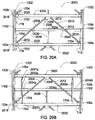
- the precast wall system 100 may include a bracing system 118 that has one or more support frames 120, 122 or 124 that are each disposed between and attached to a respective first pair of vertically interconnected precast panels (e.g., employed in groups 112a & 112b or groups 112b & 112c of the precast panels) and a respective second pair of vertically interconnected precast panels (e.g., also employed in groups 112a & 112b or groups 112b & 112c of the precast panels) that are disposed opposite to the first pair.
- a bracing system 118 that has one or more support frames 120, 122 or 124 that are each disposed between and attached to a respective first pair of vertically interconnected precast panels (e.g., employed in groups 112a & 112b or groups 112b & 112c of the precast panels) and a respective second pair of vertically interconnected precast panels (e.g., also employed in groups 112a & 112b
- the bracing system 118 may be erected in advance of orin conjunction with the first group 112a of the precast panels in order to aid in erecting and bracing subsequent groups 112b and 112c of precast panels.
- the support frames 120, 122 and 124 employed in the bracing system 118 become an integral part of the lateral force resisting system of the building when connected to the vertically interconnected pairs of precast panels as further described below.
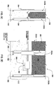
- FIG. 3A is a general cross-section view of a precast panel 200 that is representative of one implementation, however not encompassed by the present claims, for connecting an interior panel 102, a corner panel 104 or an opening panel 106, 108 or 110 to a foundation 50 or cast-in-place wall 60. As shown in FIG.
- the bottom end plate (e.g., 302) of each precast panel 102a, 104a, 106a, 108a and 110a included in the first group 112a of panels may be anchored to the foundation 50 or a cast-in-place wall 60 using one or more anchor bolts 304 that are disposed in and extend through a respective opening 306 in the bottom end plate 302 and embedded in the foundation or cast-in-place wall 60.
- the dimensions of the anchor bolts 304 are generally in the range of 2,54 cm to 10,16 cm (1 inch to 4 inches) with a yield stress of 248,211 MPa to 723,950 MPa (36 ksi to 105 ksi) for the precast panels. However, anchor bolts 304 having a larger diameter may be used to achieve a greater strength. Moreover, the dimensions of the anchor bolts 304 may vary based on the height, weight or other dimensions of the precast panel 200 in the first group 112a of panels to be anchored to the foundation as well as the panels 102, 104, 106, 108 and 110 to be vertically interconnected to the respective panel 200 in the first group 112a. Shims 308 may also be employed to align or orient the precast panel 200 relative to the foundation or cast-in-place wall 60.
- FIG. 3B is a cross-section view of another exemplary precast panel 310 consistent with the present invention that is representative of an alternate implementation for connecting an interior panel 102, a corner panel 104 or an opening panel 106, 108 or 110 to a foundation 50 or cast-in-place wall 60.
- the precast panel 310 is precast similar to the precast panel 700 described in further detail below.
- the precast panel 310 has a top end plate 702 (not shown in FIG.
- the precast panel 310 also has one or more ducts 724 extending from the top end plate 702 of the panel 310 to the bottom plate 704 of the panel 312.
- the top end plate 702 and the bottom end plate 704 of the precast panel 310 each has one or more openings 726 extending through the respective end plate 702 and 704 and in axial alignment with a respective duct 724 of the precast panel 310.
- a top portion 312 of the foundation 50 or wall 60 (which is the last portion to be formed from concrete poured to from the cast-in-place foundation 50 or wall 60) includes a cap plate 314 that serves as a base for vertically connecting precast panels 310.
- the top portion 312 may correspond to the approximately 3,048 m (10 feet) of the foundation 50 or wall under the cap plate 314.
- the last or top portion 312 of the cast-in-place foundation 50 or wall 60 may be formed to include one or more support posts 316 upon which the cap plate 314 may be disposed before pouring concrete to encase the support posts 316 and forming the top portion 312.
- Plates 318 having jacking bolts 320 may be disposed on the top of the support posts 316. Prior to pouring the concrete for the top portion 312 of the foundation 50 or wall 60, shims or jacking bolts 320 may be used (by individually threading each bolt 320 through the respective support plate 318) to adjust the level of the cap plate 314 of the foundation 50 or wall 60. Shims (e.g., 308 in Fig. 3A ) may also be employed to level the bottom end plate 704 of the precast panel 310 relative to the cap plate 314.
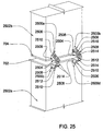
- the precast panel 310 may be further aligned to the top portion 312 of the cast-in-place foundation 50 or wall 60 using erection aids as described herein, such as in reference to Fig. 24 .
- the bottom end plate 704 and the cap plate 314 may be connected or affixed via high strength welding or bolting as described in further detail herein for vertical panel-to-panel connections, such as in reference to Figures 13A-13B and 14A-14E .
- the precast panel 310 may be vertically connected to the cap plate 314 using one or more vertical reinforcing bars or bar segments 728a in a manner similar to the vertical panel-to-panel connections described herein for precast panel 700.
- each of a first plurality of reinforcing bar segments 728a and may have one end 323 anchored or embedded in the cast-in-place foundation 50 or wall 60 and another end 322 that extends through a respective opening 324 drilled through the cap plate 314.
- a bar-to-bar coupler 326 (such as a DYWIDAG THREADBAR ® Coupler commercially available from Dywidag-Systems International) may be affixed or threaded to the end 322 of the respective reinforcing bar segment 728a extending through the cap plate 314 before the precast panel 310 is lowered into position atop the cap plate 314 of the foundation 50 or wall 60, Once the cap plate 314 is aligned with the precast panel 310, a second reinforcing bar segment 728b may then be disposed through a respective opening 726 in the top plate 702 of the precast panel 310 and into a respective duct 724 aligned with the opening 726.
- a bar-to-bar coupler 326 such as a DYWIDAG THREADBAR ® Coupler commercially available from Dywidag-Systems International
- the second reinforcing bar segment 728b may be affixed or threaded to a corresponding coupler 326 to effectively affix the two reinforcing bar segments 728a and 728b together to form one continuous vertical reinforcing bar 728 through the precast panel 310 and anchored in the cast-in-place foundation 50 or wall 60.
- Additional vertical reinforcing bars 728 may be employed in the same manner to further vertically interconnect the precast panel 310 to the cast-in-place foundation 50 or wall 60 for transfer of forces from upper tier precast panels similarly connected to the precast panel 310 to the foundation 50 or wall 60.
- Additional precast panels 102, 104, 106, 108 and 110 may be anchored to the cast-in-place foundation 50 or wall 60 in a similar manner as precast panel 310 and horizontally interconnected to from the first group 112a or precast panels in the precast wall system 100 as further described herein.
- FIGS. 3C and 3D depict another exemplary precast panel 350that is representative of an alternate implementation, however not encompassed by the claims, for connecting an interior panel 102, a corner panel 104 or an opening panel 105, 108 or 110 to a foundation 50 or cast-in-place wall 60.
- the precast panel 350 is precast similar to the precast panel 2300 described in further detail below. In particular, in the implementation shown in FIGS.
- the precast panel 350 has structural angles 2302a-2302d (2302d not in view), such as steel angles, disposed along a corner edge 2306a, 2306b, 2306c or 2306d (not in view) of the precast panel 350 and may extend between a top corner and a bottom corner of the precast panel 350.
- the structural angles 2302a-2302d may be employed to implement horizontal panel-to-panel connections and vertical panel-to-panel connections between the precast panel 350 and other horizontally and/or vertically adjacent precast interior panels having similar structural angles 2302a-2302d disposed along the corners thereof.
- a top portion 312 of the foundation 50 or wall 60 (i . e . , the last portion to be formed from concrete) poured to from the cast-in-place foundation 50 or wall 60) includes structural angles 352 (with shear studs) encased vertically in the foundation 50 or wall 60 at respective spaced apart locations near the top of the foundation 50 or wall 60 so that an exposed surface of each angle 352 will vertical align with a respective one the structural angles 2302a-2302d of the precast panel 350 when the precast panel 350 is disposed on the top of the foundation 50 or wall 60.
- a respective lap plate 354 is disposed partially over both a angle 352 encased in the foundation 50 or wall 60 and a corresponding one of the angles 2302a-2302d of the precast panel 350.
- Each lap plate 354 is then welded to both the respective foundation or wall angle 352 and the respective angle 2302 of the precast panel 350 to affix the precast panel 350 to the foundation 50 or wall 60.
- a wider lap plate 356 may be employed to partially cover and join (as welded) two horizontally adjacent corner angles (i.e., angles 2302b and 2302a in Fig. 3D ) of the two adjacent precast panels 350 with the corresponding structural angles 352 encased in the foundation 50 or wall 60.
- the precast panel 350 may also include a horizontal side plate 2316 (which is further described herein) embedded in the front side and/or back side of the precast panel 350 and connects one leg of one angle (e.g., 2302a in Fig. 3D ) to one leg of another angle (e.g., 2302b in Fig. 3D ) of the precast panel 350.
- a horizontal plate 358 may be encased in the front of the foundation 50 or wall 60 so that a lap plate 360 may extend over the horizontal side plate 2316 embedded in the precast pane! 350 and over the Horizontal plate 358 encased in the foundation 50 or wall 60 to reinforce the vertical connection between the panel 350 and the foundation 50 or wall 60.
- the side plate 2316 and the horizontal plate 358 include shear studs.
- a top view is shown of an exemplary story or floor 500 of the precast wall system 100, in which the precast wall system 100 is employed as all or a portion of the core walls of a building having perimeter walls 502, 504, 506 and 508 connected to the precast panels 102, 104, 106, 108 and 110 corresponding to at least the story or floor 500 of the precast wall system 100.
- the precast wall system 100 is employed as all or a portion of the core walls of a building having perimeter walls 502, 504, 506 and 508 connected to the precast panels 102, 104, 106, 108 and 110 corresponding to at least the story or floor 500 of the precast wall system 100.
- the perimeter walls 502, 504, 506 and 508 are constructed using steel frames 510 and may be interconnected to the back side 720 of the precast panels 102, 104, 106, 108 and 110 employed as core walls of the story or floor 500 of the precast wall system 100 via a flour slab or floor beam spanning from the respective perimeter wall to the precast panel.
- the floor slab or floor beam is interconnected to the respective precast panel using one of the slab-to-panel connections or beam-to-panel connections further described herein.
- precast panels 102,106, 108 or 110 may be used (in lieu of or in combination with steel braced frames used to form the support frames 120, 122, or 124) to form the interior web walls 520, 522 or 524 of the precast wall system 100 as shown in FIG. 5A .
- FIG. 5A In the implementation shown in FIG.
- an interior web wall 520, 522 or 524 may be formed using a T-shaped precast panel 111 or a panel to panel horizontal connection employed to interconnect to a precast panel (e.g., an interior panel 102) in an external wall 530 of the precast wall system 100 to a precast panel (e.g., another interior panel 102) in the interior web wall 520, 522 or 524 of the precast wall system 100.
- a precast panel e.g., an interior panel 102
- a precast panel e.g., another interior panel 102
- interior web walls 520, 522 or 524 may also include a precast panel 2900 that has an opening 2902 precast in the panel 2900 to form a passage, such as for a plumbing pipe, a HVAC duct, a door or for other mechanical or human passage.
- the opening 2902 may be circular, rectangular or have another shape.
- the panel 2900 having the opening 2902 is fabricated to comply with the applicable building code requirements for openings structural walls.
- an amount of reinforcement at least equal to that interrupted by the opening 2902 is added on the sides of the opening 2902, plus some additional rebars arranged tangentially about the opening 2902 to form a rebar shaped box around the opening 2902.
- This rebar reinforcement should extend at the sides of the opening 2902 a length enough to develop in tension the capacity of the rebar.
- FIG. 6 is an exemplary view of the internal side (e.g., side 512 in FIG. 5 ) of the precast wall system 100 that illustrates exemplary embodiments of interior precast panels 102, corner precast panels 104, and opening precast panels 106, 108 and 110 and Horizontal and vertical panel-to-panel connections 602 and 604 between such panels, which are however not encompassed by the present claims.
- the internal side 512 of the precast wall shown in FIG. 6 also depicts a link beam connection 606 and embedded plates (1102 in FIG. 11 ) on the font side 718 of the precast panels 102, 106, 108 or 110 employed to implement a beam-to-panel connection 608 (e.g., for supporting an interior floor slab) as further discussed herein.
- the internal side 512 of the precast wall system 100 further depicts a brace-to-panel connection 610 employed to interconnect to a support frame 120, 122, or 124 for bracing opposing pairs of vertically interconnected precast panels of the precast wall system 100.
- a brace-to-panel connection 610 employed to interconnect to a support frame 120, 122, or 124 for bracing opposing pairs of vertically interconnected precast panels of the precast wall system 100.
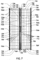
- FIG. 7 is a vertical cross-sectional view of one exemplary embodiment 700 of an interior precast panel 102, which is not encompassed by the present claims, that may be employed to construct the precast wall system 100.
- FIG. 7 also illustrates implementations of a horizontal panel-to-panel connection and implementations of a vertical panel-to-panel connection between an interior precast panel 102 and adjacent precast panels 102, 104, 106 or 108 consistent with the present invention. As shown in FIG.
- the interior precast pane) 700 includes a top end plate 702, a bottom end plate 704, and a plurality of vertical bars 706 disposed between and attached to the end plates 702 and 704 and a cementitious material 708 encasing the vertical bars 706 and defining the right side 714, left side 716, front side 718 and back side 720 of the panel 700 between the top end plate 702 and the bottom end plate 704.
- the precast panel 700 may also include a plurality of horizontal bars or transverse ties 709, each of which is connected to at least two vertical bars 706 disposed adjacent to opposing sides 714 and 716 of the panel 700.
- the interior precast panel 700 has one or more side plates 720a-720f (which may transfer shear, tension, moment, compression, or other forces or some combination thereof) to implement a horizontal panel-to-panel connection with one or two precast panels 750 that are horizontally adjacent to the right side 714 and/or left side 716 of the interior precast panel 700.
- Each precast panel 750 that is disposed adjacent. to and has a horizontal panel-to-panel connection with the interior precast panel 700 may be another interior panel 102, a corner panel 104, or an opening panel 106 or 108.
- an opening panel 110 has link beams 114 and 116 on both sides of the panel 110 that may be but are not typically interconnected to a side plate 720 as discussed herein for a horizontal panel-to-panel connection.
- Each side plate 720a-720f may include one or more shear studs 715 embedded in the cementitious material 708 to further enable the side plate (and, thus, the respective interconnected panels 700 and 750) to resist and transmit shear and other forces that typically are imposed on high-rise buildings.
- Each side plate 720a-720f may be embedded in the cementitious material 708 of the respective precast panel 700 or 750 such that the plate 720a-720f is approximately flush with the side 714 or 716 of the panel 700 or 750, enabling two adjacent panels 700 and 750 to have no or a minimal spacing between the panels.
- a fire resistant sealant or grout may be applied to any spacing or joint between the precast panels to inhibit smote from a fire outside the precast wall system 100 from passing through spacing between precast panels interconnected as disclosed herein. Accordingly, the precast wall system 100 may provide additional safety and security for a fire stairs constructed within the precast wall system 100, such as in conjunction with the bracing system 118 ( Fig. 1 .) of the precast wall system 100.
- the interior precast panel 700 may have one or more side plates 720a-720c affixed to the left side of the precast panel 700 (e.g., the first precast panel) and the other precast panel 750 (e.g., the second precast panel) has a corresponding one or more side plates 720e-720f affixed to the right side 714 of the other precast panel 750 that is adjacent to the interior precast panel 700.
- the interior precast panel 700 may have one or more side plates 720a-720c affixed to the left side of the precast panel 700 (e.g., the first precast panel) and the other precast panel 750 (e.g., the second precast panel) has a corresponding one or more side plates 720e-720f affixed to the right side 714 of the other precast panel 750 that is adjacent to the interior precast panel 700.
- the other precast panel 750 e.g., the second precast panel
- each side plate 720a-720c on the left side 716 of the interior precast panel 700 is affixed to a corresponding one of the side plates 720d-720f on the right side 714 of the other adjacent precast panel 750 via a respective weld 722, such as a high-strength weld having a strength in a range of 413,685 MPa to 758,423 MPa (60 ksi to 110 ksi).
- each side plate 720a-720f of two adjacent precast panels 700 and 750 has a width (into the page in Fig. 7 ) that is greater than the thickness of the respective panel, 700 or 750, such that each side plate 720a-720f has lip on the front side 718 and back side 720 relative to the respective panel similar to the end plates 1306 and 1308 discussed in reference to Figs. 13A and 13B below.
- each side prate 720a-720f on a first side e.g., right side 714 or left side 716) of a first precast panel 700, (or 102, 104, 106, or 108) and the lips of each corresponding side plate 720d-720f on an adjacent second side (e.g, left side 716 or right side 714) of a second precast panel 750 may be clamped or bolted together so that the respective side plates of the two adjacent precast panels are affixed to each other to transfer shear, tension, moment, compression or other forces (or some portion thereof) between the two adjacent panels 700 and 750.
- 1,805 cm (3/4 inch) diameter A325 bolts spaced at 30,48 cm (12 inches) on center to 2,54cm (1 inch) diameter A490 bolts spaced at 10,16 cm (4 inches) on center may be used to affix together the respective side plates of the two adjacent precast panels.
- FIG. 13 One implementation of a vertical panel-to-panel connection between the interior precast panel 700 and a vertically adjacent precast panel (e.g., another interior precast panel 102b, an opening precast panel 104b, or a type of opening precast panel 106b, 108b or 110b) is depicted in and described in reference to Fig. 13 .
- the top end plate 702 of the interior precast panel 700 is clamped or bolted to the bottom end plate 704 of the vertically adjacent precast panel (not shown in Fig. 7 ).
- a vertical panel-to-panel connection implemented as described herein using a top end plate and it corresponding bottom end plate of vertically adjacent panels 102, 104, 106, 108 or 110 may be positioned at a floor level of the building, or above the floor level (for example about .305 m (one foot) to 1,219 m (four feet) above floor level
- the top end plate 702 of the interior precast panel 700 is welded to the bottom end plate 704 of the vertically adjacent precast panel (not shown in Fig. 7 ).
- the precast panel 700 corresponds to a first interior precast panel 102a of the first group 112a of precast panels in the precast wall system 100.
- the precast panel 700 has one or more ducts 724 extending from the top end plate 702 of the panel 700 (e.g., the first panel 102a) towards the bottom plate 704 of the respective panel 700.
- the top end plate 702 of the precast panel 700 (e.g., 102a) has one or more openings 726 extending through the top end plate 702 and in axial alignment with a respective duct 724 of the precast panel 700.
- a second precast panel (e.g., 102b, 104b, 106b, 108b or 110b in Fig. 1 or 6 ) of the second group 112b of precast panels also has a duct 724 extending from the top end plate 702 of the second precast panel to the bottom plate 704 of the second panel (e.g., 102b, 104b, 106b, 108b or 110b), such as shown for the panel 700 in Fig. 7 .
- the two end plates 702 and 704 of the second panel each has one or more openings 726 extending through the respective plate and in axial alignment with a respective duct to of the second panel (e.g., 102b, 104b, 106b, 108b or 110b).
- Each opening 726 of the two end plates 702 and 704 of the second panel 102b, 104b, 106b, 108b or 110b may be the same size or larger than the opening 726 of the top plate 702 of the precast panel 700 (e.g., 102a) to which the second panel is to be vertically connected.
- the precast wall system also includes one or more vertical reinforcing bars 728.
- Each reinforcing bar 728 is disposed in and extends through a respective one of the ducts 724 of the second panel 102b, 104b, 106b, 108b or 110b, a respective opening 726 of the bottom end plate 704 of the second panel 102b, 104b, 106b, 108b or 110b, a respective opening 726 of the top end plate 702 of the first panel 700 or 102a and a respective duct of the first panel 700 or 102a.
- each reinforcing bar 728 may be formed from coupled vertical reinforcing bar segments 728a and 728b to define a single continuous vertical reinforcing bar 728 for implementing a vertical panel-to-panel connection among multiple vertically adjacent precast panels employed in separate tiers 112a, 112b and 112c of the precast wall system 100,
- each duct 724 of each of the first panel 700 or 102a and the second panels 102b, 104b, 106b, 108b or 110b is wider than the vertical reinforcing bar 728.
- a grout or other cement material may be disposed in each duct 724 of each of the first panel 700 or 102a and the second panel 102b, 104b, 106b, 108b or 110b to secure or affix the vertical reinforcing bar 728 to the first and second panels that are vertically connected via the respective reinforcing bar 728.
- Each end of each vertical reinforcing bar 728 may be anchored to the top side 710 of the second or last precast panel (e.g., 102b or 102c) to be vertically connected via the respective reinforcing bar 728.
- each reinforcing bar 728 may have a length sufficient to extend through three or more vertically adjacent precast panels (e.g., 102a, 102b and 102c) of the precast wall system 100.
- each reinforcing bar 728 may have a length corresponding to or greater than the six-story section of the precast wall system 100 depicted in FIG. 1 , where each precast panel 102, 104, 106, 108 and 110 has a respective length corresponding to two stories or floors of a building.
- the reinforcing bars 728 (which may be formed from coupled bar segments 728a and 728b) extend continuously through multiple vertically aligned precast panels (e.g., 102a, 102b and 102c), they provide vertical continuity throughout the building formed using the precast panels.
- the bars 728 may comprise or be made entirely of mild or high-strength steel (for example, steel having a strength in a range of 413,685 MPa to 1034,214 MPa (60ksi to 150ksi)), and used to resist significant tension forces on the walls.
- the bars 728 may be post-tensioned, depending on the expected force levels on the walls formed by the precast panels.
- each vertical panel-to-panel reinforcing bar 728 is preferably in the range of about 2,54 cm to 6,35 cm (1 inch to 2 1 ⁇ 2 inch) in diameter. However, smaller or larger diameter vertical panel-to-panel reinforcing bar 728 may be used depending on the vertical reinforcement requirements (e.g., axial loads) of the respective precast panel.
- the number and location of the vertical panel-to-panel reinforcing bars 728 within a precast panel 102, 104, 106, 108 and 110 may vary.
- each precast panel to be vertically interconnected with an adjacent precast panel preferably has two or more bars 728 per panel (to provide redundancy).
- the vertical panel-to-panel reinforcing bars 728 may be arranged symmetrically about the vertical centerline of the respective panel 102, 104, 106, 108 and 110. In the one implementation shown in Fig. 11 , the bars 728 are preferably disposed within the outer quarters of the respective panel with a horizontal bar 709 wrapped around the reinforcing bars 728 to provide lateral support of the bars 728.
- Each of the vertical reinforcing bars or bar segments 728a and 728b may be a rod or other reinforcing member.
- tensioning cables may be used as an alternative to reinforcing bars 728.
- Tensioning cables may be anchored to foundation 50 or wall 60 in a similar manner as described herein for reinforcing bars 728 (for example, as described in reference to Fig. 3B ). Tensioning cables may also be anchored within or to a precast panel in a similar manner as described for reinforcing bars 728 (for example, as described in reference to Fig. 16B ). In addition, tensioning cables or cable segments may be joined via a coupler to form a continuous panel-to-panel vertical reinforcing members as described herein for reinforcing bars 728.
- the precast panel 700 (as well as other precast panels 102, 104, 106, 108 and 110 described herein) may be manufactured using forms (not shown in figures) that temporarily hold or retain the end plates 702 and 704 relative to the vertical bars 706 and hold or retain the one or more side plates 720a-720f while the cementitious material 708 is poured inside the forms and allowed to set or cure.
- tubes or pipes such as metal or plastic pipes, having a diameter greater than the vertical reinforcing bars 728 may be inserted in and extend between the openings of the end plates 702 and 704 to form the vertical ducts 724 in the precast panel 700 before the cementitious material 708 sets or curies to form the precast panel 700.
- the tubes or bars are preferably corrugated to aid in the transfer of forces to the respective precast panel 700.
- FIG. 8 a vertical cross-sectional view is shown of an example 800 of a "left" opening precast panel 106 (as viewed from the internal or front side 718 of the panel) that may be employed to construct the precast wall system 100.
- the opening precast panel 800 may have an internal structure corresponding to an interior precast panel 700.
- the opening precast panel includes a top end plate 702, a bottom end plate 704, and a plurality of vertical bars 706 disposed between and attached to the end plates 702 and 704 and a cementitious material 708 encasing the vertical bars 706 and defining the right side 714, left side 716, front side 718 and back side 720 of the panel 800 between the top end plate 702 and the bottom end plate 704.
- the precast panel 800 may also include a plurality of horizontal bars or transverse ties 709.
- the precast panel 800 may also be formed to include vertical ducts 724 to receive vertical reinforcing bars 728 for a vertical panel-to-panel connection with a vertically adjacent precast panel 102,104, 106, 108 or 110.
- the opening precast panel 800 has side plates 720d-720f affixed to the right side 714 of the panel 106 to enable the panel 106 to form a horizontal panel-to-panel connection with an adjacent precast panel 102, 104 or 108 in a similar manner as described for the interior precast panel 700.
- the opening precast panel 106 also includes one or more link beams 114a and 114b affixed to the left side 716 of the panel 106.
- Each link beam 116a and 116b defines a respective passage or opening 802a, 802b, and 802c above and/or below the respective link beam 114a and 114b relative to an adjacent precast panel 108 or 110 to which the link beam 114a and 114b is interconnected.
- Each link beam 114a and 114b may be spaced along the side 716 of the panel 106 to permit the passage or opening 802a, 802b, and 802c to accommodate persons, plumbing, ducts or other mechanical systems required to pass through the wall formed by the respective panel 106.
- the link beams 114a and 114b may each be employed to support a floor slab for a respective story or level of the building erected using the precast wall system 100.
- a "right" opening precast panel 108 as shown in FIGS. 1 and 6 has a similar structure to the opening precast panel 106 except that the panel 108 has side plates 720a-720c affixed to the left side 716 of the respective opening panel 108 and one or more link beams 116a, and 116b affixed to the right side 714 of the panel 108 such that each link beam 116a and 116b defines a respective passage or opening 802a, 802b, and 802c above and/or below the respective link beam 114a and 114b relative to an adjacent precast panel 106 or 110 to which the link beam 116a and 116b is interconnected.
- a "left and right" opening precast panel 110 as shown in FIGS.
- link beams 114a and 114b for a left opening precast panel 106 (consistent with panel 800) is applicable to the link beams 116a and 116b of a right opening precast panel 108 and a left and right opening precast panel 110.
- each link beam 114a and 114b has a first end 804a or 804b encased in the cementitious material 708 of the left opening precast panel 800 or 108 and a second end 806a or 806b extending from the left side 716 of the opening precast panel 800
- each link beam 116a and 116b of a right opening precast panel 108 (or 902 shown in Fig. 9 ) has a first end 804 or 804b encased in the cementitious material 708 of the respective panel 108 or 902 and a second end 806a or 806b extending from the right side 716 of the opening precast panel 106.
- a right opening precast panel 108 (or the right side 714 of an opening panel 110) may be disposed adjacent to a left opening precast panel 106 (or to the left side 716 of an opening panel 110) such that the second ends 806a and 806b of the link beams 116a and 116a of the right opening precast panel 108 (or the right side 714 of the opening panel 110) and the second ends 806a and 806b of the link beams 114a and 114b of the left opening precast panel 106 or 800 (or the left side 716 of the opening panel 110) are disposed in proximity to each other and substantially axially aligned as shown in Figs. 1 and 7 .
- the second ends 806a and 806b of the link beams 114a and 114b of the left opening precast panel 106 or 110 may then be interlinked or connected to the second ends 806a and 806b of the link beams 116a and 116b of the right opening precast panel 108 or 110, for example, via a respective bolted or welded shear splice plate 808a or 808b.
- the respective two link beams 114 and 116 define the gap or opening 802a, 802b, or 802c between the left side 714 (or first side) of the left (or first) opening precast panel 106 or 110 and the right side 716 (or second side) of the right (or second) opening precast panel 108 or 110.
- the link beams 114 and 116 may comprise or be made of steel or other high-strength metal or material.
- the link beams 114 and 116 may be made of the same cementitious material 708 as the precast panel and reinforced using vertical bars 706 and/or horizontal bars 709 in a manner similar to the precast panel 700.
- the link beams 114 and 116 may have a standard 1 beam shape or other shape that enables the first end 804a or 804b of the beam 114 or 116 to be embedded and/or anchored in the respective opening precast panel 106, 108 or 110 with enough length to transfer the forces from the link beam 114 or 116 to the precast panel 106, 108 or 110.
- Each of the link beams 114 and 116 may also have one or more shear studs 715 extending from the portion of the link beam 114 or 116 embedded in the panel to effectively further reinforce the link beam 114 or 116 to the precast panel 700.
- an opening 820a or 820b may be formed in the vertical webbing of one or more of the link beams 114a and 114a formed in a precast panel 800 to function as passage for plumbing or mechanical devices.
- Each opening 820a or 820b preferably has a circular shape to limit the weakening of the link beam 114a or 114b.
- the upper link beam 114b has a first steel plate 822 affixed (e.g., via a weld) above the opening 820b and orthogonal to the webbing of the link beam 114b.
- the upper link beam 114b also has a second steel plate 824 affixed (e.g., via a weld) below the opening 820b, orthogonal to the webbing of the link beam 114b, and parallel to the first steel plate 822.
- the two parallel steel plates 822 and 824 provide additional reinforcement to the opening 820b.
- Additional reinforcement for the opening 820a through the webbing of the lower link beam 114a comprises a circular steel pipe 826 having an outside diameter substantially equal to the diameter of the opening 820a, and extending out from the webbing of the link beam 114a on both sides of the opening 820a.
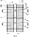
- FIG. 9 is a vertical cross-sectional view of two or more exemplary precast panels 900 and 902 that may be employed to construct the precast wall system 100.
- the precast panels 900 and 902 each has one or more horizontal ducts 904 adapted to receive a respective panel-to-panel horizontal reinforcing bar 906 for horizontally connecting the precast panels 900 and 902 to each other to implement another panel-to-panel horizontal connection alternative in accordance with the present invention.
- the two precast panels 900 and 902 illustrated in FIG. 9 are opening precast panels 106 and 108, this panel-to-panel horizontal connection may be employed to horizontal interconnect any combination of interior, corner, or opening precast panels 102, 104, 106, 108 or 110.
- FIG. 9 is a vertical cross-sectional view of two or more exemplary precast panels 900 and 902 that may be employed to construct the precast wall system 100.
- the precast panels 900 and 902 each has one or more horizontal ducts 904 adapted to receive a
- each precast panel 900 and 902 of a group of precast panels has a duct 904 extending through a left side 714 to right side 716 the entire width of the respective panel 900 or 902 and in axial alignment with the duct 904 of a horizontally adjacent precast panel 902 or 900.
- a horizontal reinforcing bar 906 (which may be a rod or other reinforcing member) is disposed in and extends through each of the axially aligned ducts 904 of the horizontally adjacent precast panels 900 and 902.
- each horizontal reinforcing bar 906 may have a bar anchor 910 attached to at least one end of the horizontal reinforcing bar 906.
- the bar anchor 910 has a shape adapted to inhibit the movement of the horizontal reinforcing bar 906 in at least one direction within the ducts 906 of the panels 900 and 902 through which the respective bar 906 extends.
- the bar anchor 910 has a greater width than the horizontal reinforcing bar 906 to inhibit movement of the reinforcing bar 906 beyond the side 714 or 716 of the precast panel 900 or 902 to which the bar anchor 910 is adapted to engage.
- the bar anchor 910 may be, for example, a high-strength nut that is affixed to a threaded end 908 of the respective horizontal reinforcing bar 906.
- a plate functioning as a washer may be placed between the nut and the edge of the precast panel 900 or 902 to further inhibit the movement of the horizontal reinforcing bar 906 beyond the side 714 or 716 of the respective panel.
- the ducts 904 through which each bar 906 extends do not need to be grouted.
- the number (and size) of horizontal reinforcing bars 906 extend through a group of horizontally adjacent panels 900 and 902 and level of post-tensioning of the bars 906 are derived based on a predetermined horizontal compressive (clamping) stress on the panels 900 and 902 that enables the shear forces on the plane of the horizontal connection to be transferred by friction between the panels 900 and 902.
- the horizontal reinforcing bars 906 may each be a rod or other reinforcing member.
- tensioning cables may be used as an alternative to horizontal reinforcing bars 906.
- Tensioning cables may be anchored at each end of the group of precast panels 900 and 902 in a similar manner as described herein for horizontal reinforcing bars 906.
- tensioning cables or horizontal reinforcing bars 906 may be joined via a coupler to form a continuous panel-to-panel horizontal reinforcing member in a similar manner as described herein for reinforcing bars 728.
- Fig. 10 a vertical cross-sectional view of another two or more exemplary, horizontally adjacent precast panels 1000 and 1002 that may be employed to construct the precast wall system 100.
- the precast panels 1000 and 1002 each has a side 714 or 716 and one or more shear keys 1004 or 1006 disposed or formed on the side of the respective panel for horizontally mating or aligning the respective panel 1000 or 1002 to another precast panel 1002 or 1000.
- the first panel 1000 e.g., an opening precast panel 108
- 1002 (e.g., an interior precast panel 102) has a second shear key (or set of shear keys) 1006 disposed or formed on the left or second side 716 of the second panel 1002 facing the right or first side 714 of the first panel 1000.
- the second shear key or key set 1006 is formed to complementary mate the first shear key or key set 1004 such that the one or more horizontal ducts 904 of the first panel 1000 are each axially aligned with the corresponding one or more horizontal ducts 904 of the second panel 1002 when the first shear key or key set 1004 is mated to the second shear key or key set 1006.
- a panel-to-panel horizontal connection shown in Fig.
- mating shear keys 1004 and 1006 employing mating shear keys 1004 and 1006, the combination of friction (due to a compressive clamping stress) and shear keys 1004 and 1006 enables the transfer of vertical shear forces between the precast panels 1000 and 1002.
- Employing mating shear keys 1004 and 1006 as described also provides the additional advantage that the required amount of horizontal post-tensioned reinforcement is reduced, as compared to the implementation in which the horizontal reinforcing bars 906 are used to connect adjacent panels 900 and 902 that do not have mating shear keys 1004 and 1006.
- the two precast panels 1000 and 1002 illustrated in Fig, 10 are depicted as an opening precast panel 108 and an interior precast panel 102, respectively, the mating shear keys 1004 or 1006 may be employed on any two abutting sides 714 and 716 of any combination of interior, corner, or opening precast panels 102, 104, 106 or 108.
- Fig. 11 is a horizontal cross-sectional view of an exemplary precast panel 1100 that may be employed to construct the precast will system 100 in accordance with the present invention.
- the precast panel 1100 corresponds to an opening precast panel 108 having a link beam 116 embedded a length (L) within the panel 1100,
- the precast panel 1100 also has a plate 1102 embedded on the front side 718 of the panel 1100 for implementing a bearn-to-panel connection 608 or a floor slab-to-panel connection 1904 in Fig. 19A as further described herein for opening precast panels as well as interior precast panels 102.
- Fig. 11 is a horizontal cross-sectional view of an exemplary precast panel 1100 that may be employed to construct the precast will system 100 in accordance with the present invention.
- the precast panel 1100 corresponds to an opening precast panel 108 having a link beam 116 embedded a length (L) within the panel 1100,
- the precast panel 1100 also has a plate
- each plate 1102 has shear studs 1104 embedded in the cementitious material 708 of the precast panel 1100 to enable the respective plate to transfer forces between the precast panel 1100 and the beam or floor slab connected to the precast panel 100 via the embedded plate 1102.
- the embedded plate 1102 is also referenced as a shear plate 1102 herein, one of ordinary skill in the art would recognize that the plate 1102 enables forces in addition to shear forces (e.g., compression, moment or tension forces) to be transferred between the respective precast panel 1100, 102, 104, 106, 108 or 110 and the beam or floor slab to which the precast panel is connected via the embedded plate 1102.
- the precast panel 1100 further has a first arrangement of horizontal bars 709, vertical bars 706 connected between the two end plates 702 and 704 of the panel 1100 and vertical panel-to-panel reinforcing bars 728 extending through the precast panel 1100.
- a respective horizontal bar 709 transverses or wraps around a respective set of at least two and preferably four vertical bars 706 or the set of two and preferably four vertical panel-to-panel reinforcing bars 728.
- the number of horizontal bars 709, the number of vertical bars 706 and the number of vertical panel-to-pinel reinforcing bars 728 are based on the predetermined strength required to resist and transfer the predicted forces and moments on the respective precast panel 1100, 102, 104, 106, 108 or 110.
- the precast panels 1100 (and other embodiments of the precast panels 102, 104, 106 108 and 110) may be subjected to high axial forces due to gravity loads (such as the self-weight of the structure and imposed loads) and lateral loads (such as wind).
- the vertically adjacent precast wall panels 102, 104, 106, 108 and 110 may be considered as individual columns. Therefore, the amount of vertical reinforcement (i.e., the number of vertical bars 706 and the number of vertical panel-to-panel reinforcing bars 728) is based on the predetermined strength required to resist and transfer the imposed forces and moments. For precast panels 102, 104, 106, 108 and 110 in which the predicted axial and moment load force levels are relatively small, minimum amounts of reinforcement are required, and the number of vertical bars 706 and vertical panel-to-panel reinforcing bars 728 may be based on applicable building codes for reinforced concrete walls or foundation. Thus, the amount of vertical reinforcement (i.e., the combination of vertical bars 706 and vertical panel-to-panel reinforcing bars 728) may range from approximately 0.12 percent to 8 percent of the horizontal cross section of the precast panel as shown in Fig. 11 .
- Horizontal bars 709 may be provided to enclose and laterally support the vertical bars 706. Horizontal bars 709 also provide additional strength to the precast panel 1100, 102, 104, 106, 108 and 110 for resisting horizontal shear forces and torsional moments (moments acting in the direction of the vertical axis of the respective panel). For precast panels 1100, 106, 108 and 110 with embedded steel link beams (i.e., opening precast panels), small openings 1106 are formed through the beam web 1108 to allow passing of the horizontal bars 709.
- grout or other cement material may be inserted into the vertical ducts 726 through which the vertical panel-to-panel reinforcing bars 728 extend in order to affix the bars 728 within the ducts 726 of the respective precast panels 102, 104, 106, 108 and 110.
- Fig. 12 is a horizontal cross-sectional view of another exemplary precast panel 1200 (e.g., an interior precast panel 102) that may be employed to construct the precast wall system 100 in accordance with the present invention.
- the precast panel 1200 has a support member or column 1202 disposed vertically within the precast panel 1200 and encased in the cementitious material 708 between the two end plates 702 and 704 (not shown in Fig. 11 ) of the panel to provide additional strength to the precast panel 1200.
- the support member 1202 may have a non-circular shape that is different than the vertical bars 706 or 728 and extends vertically within the panel 1200. In the implementation shown in Fig.
- the support member 1202 has an I shape and includes headed shear studs 1204 extending laterally from the I shape portion of the support member 1202.
- respective ends of the support member or column 1202 may be welded or bolted to the top and bottom end plates 702 and 704 of the precast panel 1200.
- the support member or column 1202 may comprise or be made of steel or other high-strength material (e.g., having a yield strength of 248,211 MPa to 448,159 MPa (36ksi to 65 ksi) to provide the panel 1200 with additional strength.
- the non-circular shape of the support member or column 1202 provides further reinforcement to the precast panel 1200.
- the support member or column 1202 reduces the amount of vertical bars 706 needed in the precast panel 1200 to meet the same predetermined strength as required for the precast panel 1100.
- employing the support member or column 1202 in the precast panel 1200 as shown and described is particularly useful when the predicted axial stresses on the panel are significant (e.g., service stresses up to 41,369 MPa (6000 psi), and the amount of vertical reinforcement required is rather large.
- Building codes may specify the location and minimum amounts of vertical and horizontal rebar reinforcement for cast-in-place concrete columns with encased steel members (i.e., composite columns).
- the combination of vertical bars 706 and vertical reinforcing bars 728 of the precast panel 1200 comprises an area of at least 0.4% of the horizontal cross sectional area of the panel 1200.
- the support member 1202 (when employed) preferably comprises an area of at least 1% of the horizontal cross sectional area of the panel 1200.
- the vertical reinforcing bars 728 are disposed at every corner of the panel 1200 and vertical bars 706 are spaced apart no further than one-half the thickness (T) of the precast panel 1200.
- the precast panel 1200 has a total area of vertical reinforcement (grouted reinforcing bars 728 and vertical bars 706) of at least 0.4% of the panel's 1200 cross sectional area.
- Horizontal bars 709 may be provided to enclose and laterally support the vertical bars 706 and the vertical panel-to-panel reinforcing bars 728.
- FIGS. 13A and 13B depict one implementation, not encompassed by the present claims, for a vertical panel-to-panel connection 604 between two exemplary precast panels 1302 and 1304 of the precast wall system 100.
- the two precast panels 1302 and 1304 are representative of any vertically adjacent combination of an interior panel 102, a corner panel 104, and an opening panel 106, 108 or 110.
- the lower precast panel 1302 has a top end plate 1306 that is aligned with and affixed to a bottom end plate 1308 of the upper precast panel 1304.
- the top end plate 1306 and the bottom end plate 1308 each has a width (Wplate) that is greater than the thickness (T.sub.u or TO of the respective vertically adjacent upper panel 1304 and lower panel 1302 such that each end plate 1306 and 1308 has a lip 1312 or 1314 on the front side 718 and back side 720 relative to the respective panel 1306 and 1308.
- Wplate width
- T.sub.u or TO thickness
- the lips 1312 of the bottom end plate 1306 and the lips 1314 of the top end plate 1308 are affixed to each other using high-strength bolts 1310 that are inserted through bores in the lips 1312 and 1314 of the end plates 1306 and 1308.
- the end of each bolt 1310 may be affixed to a corresponding nut (not shown in the figures) to further secure the ends plates 1306 and 1308 to each other.
- FIGS. 14A and 14B depict a vertical cross-sectional view of two exemplary precast panels 1402 and 1404 of the precast wall system 100 that may employ one of the vertical panel-to-panel connections depicted in FIGS. 14C, 14D and 14E to vertically interconnect the panels 1402 and 1404, however not encompassed by the present claims.
- the two precast panels 1402 and 1404 are representative of any vertically adjacent combination of an interior panel 102, a corner panel 104, and an opening panel 106, 108 or 110.
- the lower precast panel 1402 has a top end plate 1406 that may be affixed to a bottom end plate 1408 of the upper precast panel 1404 in accordance with one of the implementations depicted in FIG.
- the top end plate 1406 of the lower precast panel 1402 is longer than the bottom end plate 1408 of the higher precast panel 1404, defining a gap 1410 between the two end plates 1406 and 1408 to support a high strength weld joint 1412 that affixes the two end plates 1406 and 1408 to each other.
- the bottom end plate 1408 and the top end plate 1406 are the same size.
- a lap plate 1414 is disposed partially over both the bottom end plate 1406 and the top end plate 1408 to at least cover a joint 1416 between the two end plates 1406 and 1408. The lap plate 1414 is then welded to both the bottom end plate 1406 and the top end plate 1408 to affix the two end plates to each other.
- the bottom end plate 1408 and the top end plate 1406 are the same size.
- one of the end plates e.g., the bottom end plate 1408 of the upper precast panel 1404 is beveled at one end 1420 to enable a weld joint 1422 penetration between the two end plates 1406 and 1408 to affix the two end plates to each other.
- a magnified view is shown of a vertical bar 706 encased in an exemplary precast panel 1500 and connected to a top or bottom end plate 1502 consistent with one aspect of the present invention.
- the precast panel 1500 is representative of each embodiment of an interior precast panel 102, corner precast panel 104, or opening precast panel 106, 108, or 110 that employs a vertical bar 706 affixed between end plates 702 and 704 as discussed herein.
- the vertical bar 706 is attached to an internal surface 1504 of the end plate 1502 of the precast panel 1500 via a coupler 1506 that is welded to the respective end plate 1502.
- the coupler 1506 has one end 1508 adapted to receive an end of the vertical bar 706 and another end 1510 that is welded (via a weld joint 1512) to the end plate 1502.
- the vertical bar 706 is retained in the coupler 1506 using one or more bolts or screws 1514 that are threaded through openings in the side of the coupler 1506 until the bolts or screws engage the vertical bar 706.
- the one end 1508 of the coupler 1506 may be threaded to receive and retain the end of the vertical bar 706.
- the coupler 1506 may be a standard Type I or Type II rebar coupler, such as a model D-250 Bar Lock Structural Steel Connector commercially available from Dayton Superior.
- Fig. 15B is a magnified view of another coupler and welding arrangement for attaching a vertical bar 706 encased in an exemplary precast panel 1550 consistent with the present invention.
- the end 1510 of the coupler 1556 that is welded to the end plate 1502 is tapered inwards to enable a complete-joint penetration weld joint 1512 to be employed to affix the coupler 1556 to the end plate 1502.
- Fig. 16 illustrates a vertical cross-sectional view of two exemplary precast panels 1602 and 1604 vertically connected.
- the two precast panels 1602 and 1604 are representative of any vertically adjacent combination of an interior panel 102 a corner panel 104, and an opening panel 106, 108 or 110.
- the top one 1604 of the two precast panels may be thinner than the bottom precast panel 1602.
- the bottom end plate 704 of the top precast panel 1604 may be shorter (in the thickness direction or front side 718 to back side 720) than the top end plate 702 of the bottom precast panel 1602, enabling the two end plates 702 and 704 to be welded together via a lap weld joint 1606 and/or a lap plate welded to both end plates 702 and 704.
- the end plates 702 and 704 each may be longer in the thickness direction of the two panels 1602 and 1604 so that each end plate 702 and 704 has a respective lip through which the end plates 702 and 704 may be bolted using high strength bolts as discussed herein, for example, in reference to Fig. 13 .
- Fig. 16B is a vertical cross-sectional view of another two precast panels 1650 and 1652 vertically connected.
- the two precast panels 1650 and 1652 are representative of any vertically adjacent combination of an interior panel 102, a corner panel 104, and an opening panel 106, 108 or 110. Similar to the precast panels 1602 and 1604 in Fig. 16A , the upper or top one of the two precast panels is thinner than the lower or bottom precast panel 1650.
- each panel 1650 and 1652 has one or more vertical ducts 724 adapted to deceive a respective reinforcing bar segment 728a or 728b that are connected via a bar-to-bar coupler 326 to form a single continuous vertical reinforcing bar 728 that vertically connects the two panels to each another. Since the lower precast panel 1650 is thicker than the upper precast panel 1652, the lower precast panel 1650 may include more ducts 724 than the upper precast panel 1652 or have one or more ducts (e.g., duct 724x in Fig. 16B ) that does not align with corresponding duct in the upper precast panel 1652.
- the additional duct 724x in the lower precast panel 1650 may have a bar anchor 1654 at one end of the duct 724x to anchor a vertical reinforcing bar segment 728b that extends from the lower precast panel 1650 to a vertically adjacent precast panel in a tier (e.g., 112a) below the panel 1650 or to a foundation wall (not shown in Fig. 16B ).
- a bar anchor 1654 at one end of the duct 724x to anchor a vertical reinforcing bar segment 728b that extends from the lower precast panel 1650 to a vertically adjacent precast panel in a tier (e.g., 112a) below the panel 1650 or to a foundation wall (not shown in Fig. 16B ).
- the lower precast panel 1650 may be cast to have a duct 724z that does not extend through the bottom end plate 704 of the panel 1650 and is axially aligned with the duct 724y of the upper precast panel 1652.
- the duct 724z may have a bar anchor 1656 at the one end of the duct 724z that is closest to the bottom end plate 704 of the lower precast panel 1650.
- Figs. 16C-16B depict four precast interior panels 1660, 1662, 1664 and 1666 that are vertically and horizontally connected in accordance with the present invention.
- the top two 1660 and 1662 of the four precast panels are thinner than the bottom two precast panels 1664 and 1666.
- each panel 1660, 1662, 1664 and 1666 has a plurality of structural angles 2302a-2302d (such as steel right angles) consistent with the precast panel 2300 described herein.
- Each angle 2302a-2302d is disposed along a corner edge of the respective precast panel 1660, 1662, 1664 and 1666 and may extend between a top corner and a bottom corner of the precast panel 1660, 1662, 1664 and 1666 such that each angle 2302a-2302d is adapted to connect (for example, via a high strength weld) the respective precast panel (e.g., 1660) to another horizontally adjacent precast panel (e.g., 1662) and/or to another vertically adjacent precast panel (e.g., 1666).
- the respective precast panel e.g., 1660
- another horizontally adjacent precast panel e.g., 1662
- another vertically adjacent precast panel e.g., 1666
- the panel system includes one or more transfer members 1670 having a width equal to the change of thickness ( ⁇ t) of the lower and upper precast panels (e.g., difference in front to back sides of panels 1662 and 1664 in Fig. 16C ).
- Each transfer member 1670 may be a solid steel bar, a hollow rectangular steel tube, or other transfer member having a yield strength in a range of 248,211 MPa to 448,159 MPa (36ksi to 65ksi).
- Each transfer member 1670 is affixed (e.g., via a weld) to the vertical structural angle 2302a or 2302b of the upper precast panel 1660 or 1662 and a portion or lip 1672 of the bottom end plate 704 extending from the upper precast panel 1660 or 1662.
- the lip 1672 of the bottom end plate has a width corresponding to the change of thickness ( ⁇ t) of the lower and upper precast panels 1660, 1662 and 1664, 1666.
- Each transfer member 1670 may be affixed to the respective upper precast panel during the precast fabrication process of the respective upper precast panel.
- a connection plate 1772 as shown in Fig. 16C spans and is affixed to (e.g., via a weld) the corner edge angle 2302a and 2302b of the lower precast panel and the transfer member 1670 that is affixed to the corresponding corner edge angle 2302a and 2302b of the upper precast panel.
- Each connection plate 1772 may be comprised of steel or other comparable high strength material.
- each upper precast panel 1660 and 1662 is affixed to the top end plate 702 of the vertically adjacent lower precast panel 1666 or 1664 using a partial joint penetration weld.
- an embedded horizontal plate 1774 is embedded in and spans the sides 712 and 714 of the upper precast panel (e.g., panel 1662 in Fig. 16C ) to connect the vertical corner angles 2302b and 2302c (or 2302a and 2302d) on opposing sides of the panel.
- Fig. 17 depicts an exploded view of two precast panels 106a and 108a (depicted in the precast wall shown in Fig. 6 ) that are horizontally connected in accordance with a Horizontal panel-to-panel connection 602 and vertically connected to two other precast panels 106b and 108b in accordance with a vertical panel-to-panel connection 604
- An internal surface or front side 718 of at least one of the precast panels includes an embedded beam segment 1702 for connecting to a beam disposed orthogonal to the panel 108a and an embedded gusset plate 1704 for connecting a brace member (of a support frame 120, 122, or 124 of the precast wall system 100) at an angle diagonal to the internal surface 718 of the precast panel 108a as described in further detail herein and, in particular to Figs. 20 and 21 .
- Each of the precast panels 108a and 106a also include one or more embedded plates 1102 for implementing a beam-to-
- each embedded beam segment 1702 and embedded gusset plate 1704 are depicted in Fig. 17 as included in a left opening precast panel 108, each may be employed in a similar manner in an interior panel 102, a corner panel 104, or another type of opening precast panel 106 or 110 in order to interconnect to a support frame 120, 122, or 124 of the precast wall system 100.
- each embedded plate 1102 is depicted in Fig.
- an opening precast panel 106 or 108 each may be employed in a similar manner in an interior panel 102, a corner panel 104, or another type of opening precast panel 110 in order to implement a beam-to-panel connection 608 to support, for example, a respective floor slab 1706 and 1708.
- Fig. 18A a vertical cross-sectional view is shown of a portion of one of the precast panels (e.g., 108a) in Fig 17 that is referenced generally as the precast panel 1800.
- Fig. 18A illustrates one implementation for a beam-to-panel connection 608 in accordance with one aspect of the present invention.
- the precast panel 1800 includes a shear tab 1802 that is affixed (via a high-strength weld or other bond) to an embedded plate 1102 of the precast panel 1800 so that the shear tab 1802 is orthogonal to the front side 718 of the precast panel.
- the shear tab 1802 may be affixed or welded to the beam 1804. In another implemation, the shear tab 1802 may have one or more bolt openings 1806 for bolting (via high-strength bolts 1808) the shear tab 1802 to the end of the beam 1804.
- each panel 102, 104, 106, 108 and 110 may have shear studs 1104 attached to the shear plate 1102 and embedded in the cementitious material 708 of the respective precast panel 102, 104, 106, 108 and 110.
- the beam 1804 may be welded directly to the embedded plate 1102 of the precast panel 1800.
- a metal deck or web 1810 may then be disposed on the beam 1804 and a horizontally adjacent beam (not shown in Fig. 18A ).
- a floor slab 1812 may be formed (e.g., using concrete or another cementitious material) over the the metal deck 1810 and floor beam 1804.
- the precast panel 1800 may be precast to include a plurality of horizontal bars 1814 as shown in Figs. 18A and 18B .
- each Horizontal bar 1814 is attached to one end 1818 of a respective Type I or Type II coupler 1816 that has a socket 1820 at the other end 1822 of the coupler 1816.
- the couplers 1816 are disposed along a lateral (side 714 to side 716) axis of the panel 1800 relative to a predetermined floor slab level and encased in the cementitious material 708 of the precast panel 1800.
- another horizontal end bar 1824 may be inserted or threaded in the socket 1820 of each coupler 1816 of the panel 1800.
- each horizontal bar 1824 is engaged in a respective coupler socket 1820, concrete or other cementitious material may be poured over the metal deck or web 1810 and the horizontal bars 1824 to form the floor slab 1812 and to encase the horizontal bars 1824 in the floor slab 1812, connecting the floor slab 1812 to the panel 1800.
- each horizontal bar 1814 of the precast panel 1800 is not connected to a respective coupler 1816. Instead, each horizontal bar 1814 has one end 1826 encased in the cementitious material 708 of the precast panel 1800 and another end 1828 that extends though a trench 1830 running in a lateral axis (e.g., side 714 to side 716) of the panel 1800 and extending beyond the front side 718 of the panel.
- a lateral axis e.g., side 714 to side 716
- the trench 1830 has a depth sufficient to enable the end 1828 of each of the horizontal bars 1814 to be bent within the trench 1830 towards the right side 714 or the left side 716 of the panel 1800 such that the portion of each horizontal bars 1814 that extends beyond the front side 718 of the panel 1800 before bending are disposed within the trench or extend to the right or left sides 714 and 716 of the panel as shown in Fig. 18C .
- each of the horizontal bars 1814 may be bent back or straightened so that the end 1828 extends beyond the front side 718 of the panel 1800 in a plane corresponding to the plane of the floor slab 1812 to be formed.
- concrete or other cementitious material may then be poured over the metal deck or web 1810 (or other temporary or permanent forms for a floor slab) and the portion of the horizontal bars 1814 extending beyond the trench 1830 to form the floor slab 1812 and to encase the portion of the horizontal bars 1814 extending beyond the trench 1830 in the floor slab 1812, connecting the floor slab 1812 to the panel 1800.
- Fig 18D is a perspective view and Fig. 18E is a vertical cross-section view of another embodiment of the precast panel 1800 consistent with the present invention, illustrating another implementation for connecting a floor slab that is not disposed over a floor beam or metal deck to the precast panel.
- the panel 1800 combines the trench 1830 feature with the horizontal bar 1814 and coupler 1816 feature to form a floor slab connection without the support of a lower floor beam.
- the panel 1800 has a trench 1830a and 1830b running in a lateral axis (e.g., side 714 to side 716) of the panel 1800 for each floor slab 1812 to be connected to the panel 1800.
- the precast panel 1800 in this implementation is precast to include a plurality of horizontal bars 1814 that are encased in the panel 1800 (in two rows in Figs. 18D-18E ) along each trench 1830a and 1830b.
- Each horizontal bar 1814 is attached to one end 1818 of a respective Type I or Type II coupler 1816 that has a socket 1820 at the other end 1822 of the coupler 1816 as shown in Fig. 18E .
- the couplers 1816 are disposed along to be flush with a bottom side of the respective trench 1830a or 1830b.
- another honzontal end bar 1824 may be inserted or threaded in the socket 1820 of each coupler 1816 of the panel 1800.
- concrete or other cementitious material may be poured over the metal deck or web 1810 or other form supports for forming the floor slab 1812 within the respective trench 1830a or 1830b, connecting the floor slab 1812 to the panel 1800.
- Each floor slab 1812 may be formed with rebar or other reinforcement bars 1832.
- Fig. 19A is a vertical cross-sectional view of the portion of another exemplary precast panel 1900, illustrating another implementation for connecting the precast panel 1900 to a floor slab 1902 that is not disposed over a floor beam.
- Fig. 19B is a perspective view of the precast panel 1900 and the floor slab-to-panel connection 1904 between the floor slab 1902 and the precast panel 1900
- the precast panel 1900 is representative of an interior panel 102, a corner panel 104, and an opening panel 106, 108 or 110 that may be required to support a floor slab. As shown in Figs.
- the precast panel 1900 may include one or more plates 1102 embedded on the front side 718 of the panel 1900 for implementing a respective floor slab-to-panel connection rather than a beam-to-panel connection.
- Each embedded plate 1102 may have one or more shear studs 1104 extending into and embedded in the cementitious material 708 of the precast panel 1900.
- each embedded plate 1102 as employed in a precast panel 1900 is adapted to transfer shear forces as well as tension or other forces that may be imposed on the respective panel to another precast panel interconnected via the embedded plate 1102.
- a bracket or L-shaped angle 1906 is affixed to each embedded plate 1102 such that a shelf 1907 defined by the bracket or angle 1906 is disposed parallel to a lateral (or side 714 to side 716) axis of the panel 1900.
- a metal deck or web 1910 may then be disposed on the shelf 1907 of the panel 1900 as well as the shelf 1907 or beam 1804 connected to other panels 1900 or 1800 of the group 112a, 112b or 112c of precast panels 102,104, 106, 108 or 110 that are horizontally interconnected to form a floor of the stories of the building defined by the respective group 112a, 112b or 112c of precast panels.
- One or more headed shear studs 1908 may be welded or otherwise attached to the bracket or angle 1902 through the metal deck or web 1910 so that each shear stud 1908 extends from the shelf 1907 of the bracket or angle 1906.
- a floor slab 1902 may then be formed (e.g., using concrete or another cementitious material) over the the metal deck 1910 and the shear studs 1908 of the bracket or angle 1906 supporting the metal deck 1910.
- metal deck or web 1910 is replaced with a solid concrete slab 1912 as depicted in Figs. 19C and 19D .
- metal rebar 1914 may be embedded in the precast panel 1900 and may connected to at least one horizontal threaded tie bar 1916 embedding in the solid concrete floor slab 1912 via a coupler 1918.
- FIG. 20A an exemplary support frame 2000 is depicted that may be employed between and connecting opposing precast panels 102, 104, 106, 108 or 110 in the precast wall system 100 in accordance with the present invention.
- FIG. 20B depicts one embodiment of the support frame 2000 in which temporary posts 2055a and 2055b are employed to support the support frame 2000 when attached to a foundation 50 or foundation wall 60 before a first of the precast panels in the first tier 112a is erected to form the precast wall system 100.
- the support frame 2000 when erected in the precast wall system 100, the support frame 2000 is used as the permanent core floor framing.
- the exemplary support frame 2000 is representative of one embodiment of the support frames 112a, 112b, or 112c that may be employed to brace opposing precast panels 102, 104, 106, 108 or 110.
- Each support frame 2000 is disposed between and attached to a respective first pair of vertically interconnected precast panels and a second pair of vertically interconnected precast panels that are disposed opposite to the first pair in the precast wall system 100.
- the first pair of vertically interconnected precast panels may correspond to the first pair of vertically interconnected interior panels 102a and 102b, where the interior panel 102a is one of the first group 112a of horizontally connected precast panels 102, 104, 106, 108 and 110 and the interior panel 102b is one of the second group 112b of horizontally connected precast panels 102, 104, 106, 108 and 110 employed in the precast wall system 100.
- the second pair of vertically interconnected precast panels may be a pair of vertically interconnected opening panels 106a and 106b that disposed opposite to the first pair of vertically interconnected interior panels 102a and 102b of the precast walls system as reflected in Figs. 1 and 6 .
- first pair of precast panels 102a and 102b and the second pair of precast panels 106a and 106b may be any vertical pair combination and opposing vertical pair combination of the precast panels 102, 104, 106, 108 and 110 of the precast wall system 100, where the vertical pair of precast panels are formed to have connections to the support frame 2000 as described herein.
- each support frame 2000 includes one or more cross beams 2002, 2032, and 2034 that provide bracing support for opposing walls of a tier of precast panels to be erected as well as function as floor framing when installed in the precast wall system 100.
- each precast wall panel e.g., panels 102b and 106b
- two cross beams e.g., 2002 and 2034
- each precast wall panel 102b and 106b may be precast to be connected to one respective cross beam (e.g., to provide floor framing corresponding to one floor of a single story precast wall system 100 and building).
- the cross beam 2032 may be erected or installed first and may be connected to the opposing foundation walls 60 or previously erected opposing precast panels (e.g., lower precast panels 102a and 106a in Figs. 20A and 20B ) of a firs tier 112a of the precast wall system 100.
- opposing foundation walls 60 may be formed in accordance with the present invention to have the same support frame connections.
- opposing foundation walls 60 or each of the lower one (e.g., 102a and 106a) of the opposing pairs of vertically interconnected precast panels includes a beam segment 1702 having a first end 2018 encased in the cementitious material 708 of the respective panel 102b or 106b (or foundation wall 60) and a second end 2020 extending from an internal or front side 718 of the respective panel 102b or 106b (or foundation wall 60).
- the cross beam 2032 is connected to the beam segment 1702 of each of opposing lower precast panels 102a and 106a (or opposing foundation walls 60). As shown in Fig.
- the end segment 1702 of each precast panel 102a and 106b may be affixed to the cross beam 2032 via a web splice plate 2022 that may affixed to the respective end segment 1702 and the cross beam 2032 via a high strength weld 2024 or high strength bolts 2026 or rivets, or a combination thereof.
- the connecting end 2020 of the respective end segment 1702 has two flanges 2030a and 2030b that define an opening through which a respective end of the cross beam 2032 may be inserted
- each flange 2030a and 2030b may be bolted or welded to the respective end of the cross beam 2032 to provide additional reinforcement to the connection between the beam segment 1702 and the cross beam 2032.
- each precast panel 102a, 102b, 106a and 106b that has a beam segment 1702 for connecting to a support frame 2000 may also include a support member or column 1202 centrally and vertically encased in the cementitious material 708 of the respective precast panel.
- the embedded end 2018 of the beam segment 1702 may be affixed to the support member or column 1202 via a high strength weld 2028 or bolts (not shown in Fig. 21 ) to provide further strength to the beam-to-panel connection formed using the embedded beam segment 1702.
- the support frame 2000 may include one or more removable temporary posts 2055a and 2055b or false works that are used to aid in the erection of the one or more cross beams 2002 and 2034, which will then be connected between the opposing upper precast panels 102b and 106b as each of these panels are erected.
- each temporary post 2055a and 2055b may include two inner posts 2056a and 2056b each having a top and a bottom, a top cross member 2057a removably attached to the top of each inner post 2056a and 2056b, and a bottom cross member 2057b removably attached to the bottom of each inner post 2056a and 2056b.
- the cross members 2057a and 2057b may be removably attached to the inner posts 2056a and 2056b via bolts (not shown in the figures) or other removable fasteners standard to the construction industry.
- the inner posts 2056a and 2056b and the top cross member 2057a and bottom cross member 2057b define a space 2060a to enable the passage of a brace member 2004 or 2012 of the support frame 2000 through the respective temporary post 2055a or 2055b as further described herein.
- Each temporary post 2055a or 2055b may also have 2058 an intermediate cross member 2058a removably attached to and disposed between (or external to) the inner posts 2056a and 2056b at the elevation of the underside of the beam 2034 so that the intermediate cross member 2058 may be used to aid in the positioning and temporary support of a portion of beam 2034 (e.g., beam segment 2034a).
- the inner posts 2056a and 2056b, the top cross member 2057a and the intermediate cross member 2058 define an upper space 2060b to enable the passage of a portion of beam 2034 (e.g., beam segment 2034a).
- each temporary post 2055a and 2055b includes an intermediate cross member 2058 as shown in Fig.
- the inner posts 2056a and 2056b, the bottom cross member 2057b and the intermediate cross member 2058 define a lower space 2060a to enable the passage of a brace member 2004 or 2012 of the support frame 2000 through the respective temporary post 2055a or 2055b.
- one of the temporary posts 2055a may be erected and positioned at one end of beam 2032.
- Another temporary post 2055b may then be erected on the opposite end of beam 2032.
- Each of the temporary posts 2055a and 2055b are oriented on the beam 2032 interconnected between the lower precast panels 102a and 106a so that the opening or spaces 2060a and 2060b between the inner posts 2056a and 2056b of each of the temporary posts 2055a and 2055b are axially aligned with the beam 2032 and with the beam 2034 to be interconnected between the upper precast panels 102b and 106b as further described below.
- the beam 2002 may be erected and supported on top of the temporary posts 2055a and 2055b.
- the support frame 2000 may include one or more diagonal brace members 2004 and 2012,
- each of the lower precast panels 102a and 106a (or opposing foundation walls 60) has a gusset plate 1704 extending from an internal or front side 718 of the respective lower precast panel (or foundation wall 60).
- each brace member 2004 and 2012 is inserted through the space 2060a between the inner posts 2056a and 2056b of a respective temporary post 2055a or 2055b and then connected to the gusset plate 1704 of a respective one of the lower precast panels 1 02a and 106a (or opposing foundation walls 60).
- the top end of each brace member 2004 and 2012 is connected to a gusset plate 2008 that is affixed to and extends from the cross beam 2002 as shown in Figs. 20A and 20B .
- the gusset plate 1704 of each of the lower precast panels 102a and 106a may be supported by or rest on (and be welded to) the beam segment 1702 of the respective lower precast panel 102a or 106a to connect to the diagonal brace member 2004 or 2012.
- the beam 2034 comprises beam sections 2034a, 2034b and 2034c, which are interconnected via splicing plates 2038 and 2040 so that the diagonal brace members 2004 and 2012 pass diagonally through the beam 2034.
- the first beam section 2034a may be inserted through the space 2060b between the inner posts 2056a and 2056b of the temporary post 2055a and supported on the intermediate cross member 2058 of the same temporary post 2055a.
- the third beam section 2034c may be inserted through the space 2060b between the inner posts 2056a and 2056b of the temporary post 2055b and supported on the intermediate cross member 2058 of the same temporary post 2055b.
- a splicing plate 2038 may be affixed to and between facing ends of the first beam section 2034a and the second beam section 2034b so that the brace member 2004 passes between the first and second beam sections 2034a and 2034b.
- a splicing plate 2040 may be affixed to and between facing ends of the second beam section 2034b and the third beam section 2034c so that the brace member 2012 passes between the second and third beam sections 2034b and 2034c.
- each splicing plate 2038 and 2040 is affixed to a web portion of the ends of the beam sections 2034a and 2034b or 2034b and 2034c such that the brace member 2004 or 2012 (which is offset from the center or web axis of the beam 2034 by at least the width of the gusset plate 1704 to which the brace member 2004 or 2012 is affixed) passes along side the respective splicing plate 2038 or 2040.
- the splicing plates 2038 and 2040 may be affixed to respective beam sections 2034a, 2034b and 2034c via mild or high strength bolts and/or welds (not shown in Figs 20A or 20B ).
- the support frame 2000 may also include a column 2036 connected (e.g., via welding or bolting) between the cross beam 2034 and the lower cross beam 2032 as shown in Fig. 20A .
- Optional column 2036 may also be used to assist in the erection of beam section 2034c.
- Fig. 20D depicts another support frame 2050 that may be used for connecting opposing precast panels (102a & 102b and 106a & 106b) in the precast wall system 100 in accordance with the present invention. Except as described bellow, the support frame 2050 has components (such as cross beams 2002, 2032, and 2034 and brace members 2004 and 2012) that are erected consistent with the support frame 2000. However, in the implementation shown in Fig. 20D , instead of temporary posts 2055 extending between cross beams 2002 and 2032, the support frame 2050 includes one or more removable or temporary posts 2054a and 2054b mounted between the cross beam 2032 and the next higher cross beam 2034 to be connected between the opposing upper precast panels 102b and 106b.
- the support frame 2050 instead of temporary posts 2055 extending between cross beams 2002 and 2032, the support frame 2050 includes one or more removable or temporary posts 2054a and 2054b mounted between the cross beam 2032 and the next higher cross beam 2034 to be connected between the opposing
- the diagonal brace members 2004 and 2012 are each comprised of brace member sections 2004a, 2004b and 2012a, 2012b.
- the lower end of each brace member 2004a and 2012a is connected to the gusset plate 1704 of a respective one of the lower precast panels 102a and 106a (or opposing, foundation, walls 60).
- the top end of each brace member 2004a and 2012a is connected to another respective gusset plate 2005a or 2005b that is affixed to and extending from the cross beam 2034 as shown in Fig. 20D .
- one or more temporary posts 2052a and 2052b may be mounted between the cross beam 2034 and the next higher cross beam 2002 to be connected between the opposing upper precast panels 102b and 106b to be erected as shown in Fig. 20D .
- each brace member 2004b and 2012b is connected to a respective gusset plate 2005c or 2005d that is affixed to and extending from the cross beam 2034 as shown in Fig. 20D .
- the top end of each brace member 2004b and 2012b is connected to the cross beam 2002, via the gusset plate 2008 attached to the cross beam 2002 at a center portion thereof.
- multiple support frames 120, 122 and 124 may be constructed and arranged in a parallel manner across respective pairs of opposite precast panels of the first or current tier of the precast wall system 100.
- the support frames 120, 122, and 124 may have interconnecting members (not numbered in Figs. 1 and 5 ). Once the members of each support frame 120, 122 and 124 are erected, plumbed and bolted, opposing pairs of precast panels 102b and 106b in the next tier may be erected to connect to a respective support frame 120, 122, or 124.
- the cross beam 2034 of the respective support frame 2000 or 2050 is connected to a shear plate 1102 embedded in the internal or front side 718 of the higher one 102b of the First pair of precast panels 1 02a and 102b and to a shear plate 1102 embedded in the internal or front side 718 of the higher one 106b of the second pair of precast panels 106a and 106b.
- the beam-to-panel connection 608 that may be employed to connect the cross beam 2034 to the respective precast panels 102b and 106b may correspond to the beam-to-panel connection described in reference to Fig. 18A .
- a shear tab 1802 may be affixed (via a high-strength weld or other bond) to the embedded shear plate 1102 of the precast panel 102b and 106b so that the shear tab 1802 is orthogonal to the front side 718 of the precast panel 102b and 106b.
- the shear tab 1802 may be affixed or welded to the beam 2034.
- the shear tab 1802 may have one or more bolt openings 1806 for bolting (via high-strength bolts) the shear tab 1802 to the end of the cross beam 2034.
- the cross beam 2002 of the respective support frame 2000 or 2050 is connected (e.g., in the same manner as described for cross beam 2032) to a beam segment 1702 embedded in the upper one 102b of the first pair of precast panels 102a and 102b and a beam segment 1702 embedded in the upper one 106b of the second pair of precast panels 106a and 106b.
- the precast panels (e.g., panels 102b and 106b in Fig. 20B or Fig. 20D ) for the current tier (e.g., group) 112b) of the precast wall system 100 are vertically connected to respective lower tier panels (e,g., panels 102a and 106a of group 112a) and horizontally connected to respective adjacent panels in the same tier (e.g., group 112b), the temporary posts 2055a and 2055b of the support frame 2000 and the temporary 2052a, 2052b, 2054a and 2054b of the support frame 2050 may be removed as shown in Fig. 20A and used for erection of the next tier of support frames 120, 122, and 124.
- the temporary posts 2055a and 2055b of the support frame 2000 and the temporary 2052a, 2052b, 2054a and 2054b of the support frame 2050 may be removed as shown in Fig. 20A and used for erection of the next tier of support frames 120,
- the column 2036 may remain as part of the support structure 2000 and 2050 and the bracing system 118 to support the span of beam 2034 for floor framing.
- Cross beams 2032, 2034 (including splicing plates 2038 and 2040 in support frame 2000) and 2002 also remain as permanent framing members for the bracing system 118 to support the core floor decking and concrete slab.
- the support frame 2000 and 2050 as described provides bracing support for the first group 112a of panels horizontally interconnected to the opposing lower precast panels 102a and 106a and to the second group 112b of panels that are or are being set in place to be interconnected to the opposing higher precast panels 102b and 106b that are vertically interconnected to the lower precast panels 102a and 106a.
- each support frame 120, 122 and 124 may be expanded or vertically interconnected to another similarly formed support frame 2000 or 2050 to continue to construct or erect the precast wall system 100 for the building.
- the next or other support frame 2000 or 2050 would similarly support opposing pairs of precast panels that include the opposing higher precast panels 102b and 106b and the next opposing higher precast panels (e.g., 102c and 106c) that are vertically connected to the precast panels 102 and 106b.
- Fig. 22A depicts a horizontal cross-sectional view of another two exemplary precast panels 2200 and 2202 that may be employed to construct the precast wall system 100 in accordance with the present invention. Similar to precast panels 1000 and 1002 depicted in Fig. 10 , the precast panels 2200 and 2202 each has a side 714 or 716 and one or more shear keys 1004 or 1006 disposed or formed on the side of the respective panel for horizontally mating or aligning the respective panel 2200 and 2202 to the other precast panel 2202 and 2200.
- the second shear key or key set 1006 is formed to complementary mate the first shear key or key set 1004 such that the one or more horizontal ducts 904 of the first panel 2200 are each axially aligned with the corresponding one or more horizontal ducts 904 of the second panel 2202 when the first shear key or key set 1004 is mated to the second shear key or key set 1006.
- the precast wall system 100 includes one or more post-tensioned horizontal reinforcing bars 2204 disposed in the respective ducts 904 with a bar anchor 910 attached to each end of the respective horizontal reinforcing bar 2204
- the combination of friction (due to the compressive clamping stress of the post-tensioned horizontal reinforcing bars 2204) and the shear keys 1004 and 1006 enables the transfer of horizontal shear forces between the two precast panels 2200 and 2202 such that the panels are able to resist large horizontal shear forces perpendicular to the plane of the wall defined by the precast panels 2200 and 2202, for example due to blast loading
- the combination of the post-tensioned horizontal reinforcing bars 2204 and shear keys 1004 and 1006 enables the precast panels 2200 and 2202 to inhibit the passage of flame or hot gases through the shear key joint 2206 between the two panels 2200 and 2202.
- Fig. 22B is a horizontal cross-sectional view of another two exemplary precast panels 2210 and 2212 that may be employed to construct the precast wall system 100 in accordance with the present invention.
- the joints e.g.. 2214
- the joints inhibit the passage of flame or hot gases in compliance with the ASTM E 1966 standard for testing and rating fire-resistance joint systems made in or between fire-resistance-rated assemblies. As shown in Fig.
- one of the precast panels 2210 has a pocket or indentation 2216 on and extending the vertical height of the side 714 of the panel 2210 that is to be connected with the side 716 of the adjacent panel 2212.
- the side 716 of the adjacent panel 2212 may be planar or also have a vertical indentation 2216.
- the joint 2214 between the two precast panels 2210 and 2212 may be fire and smoke sealed using a flexible non-combustible material, such as a ceramic fiber blanket that is tested and fire-resistance rated in accordance with the applicable standard, for example ASTM E 1966.
- a flexible non-combustible material such as a ceramic fiber blanket that is tested and fire-resistance rated in accordance with the applicable standard, for example ASTM E 1966.
- Fig 23A a vertical cross-sectionat front view of another precast panel 2300 is shown, which may be employed to construct the precast wall system 100.
- Fig. 23B depicts a left side view of the precast panel 2300 and
- Fig. 23C depicts a horizontal cross-sectional view of the same precast panel 2300.
- the precast panel 2300 has a plurality of structural angles 2302a-2302d comprised or made entirely of mild or high-strength metal (for example, steel having a yield strength in a range of 248,211 Mpa to 344,738 Mpa (36 ksi to 50 ksi).
- mild or high-strength metal for example, steel having a yield strength in a range of 248,211 Mpa to 344,738 Mpa (36 ksi to 50 ksi).
- each angle 2302a-2302d is disposed along a corner edge 2306a, 2306b, 2306c or 2306d of the precast panel 2300 and may extend between a top corner 2308a, 2308b, 2308c or 2308d and a bottom corner 2310a, 2310b, 2310c or 2310d of the precast panel 2300 such that each angle 2302a-2302d is adapted to connect (for example, via a high strength weld) the precast panel 2300 to another horizontally adjacent precast panel 2300 and/or to another vertically adjacent precast panel 2300.
- each angle 2302a-2302d may comprise two or more angle segments spaced apart on a respective corner edge 2306a-2306d of the panel 2300.
- each angle 2302a-2302d has a first portion or leg 2304a that extends along and is embedded in either the right side 714 or left side 716 of the panel 2300 and a second portion or leg 2304b that extends along and is embedded in either the front side 718 or the back side 720 of the panel 2300.
- Each angle 2302a-2302d may have one or more shear studs 1104 affixed to (e.g., welded to) and extending from each leg of the respective angle into the cementitious material 708 of the precast panel 2300 so that the respective angle is further effective to transfer forces between the precast panel 2300.
- each leg 2304a and 2304b at each end of each angle 2302a-2302d may be affixed to (e.g., via a high strength weld) to the end plates 702 and 704 of the panel 2300.
- each leg 2304a and 2304b at each end of each angle 2302a-2302d may be connected to a respective end plate 702 or 704 via a stiffening plate 2312 or 2314 embedded in the same side 714, 716, 718 or 720 of the panel 2300 as the leg 2304a or 2304b of the respective angle 2302a-2302d.
- the precast panel 2300 may also include one or more horizontal side plates 2316.
- Each horizontal side plate 2316 is embedded in the front side 718 or back side 720 of the precast panel 2300 and connects one leg of one angle (e.g., 2302a or 2302d) to one leg of another angle (e.g., 2302b or 2302c).
- Each horizontal side plate 2316 may have one or more shear studs 1104 affixed to and extending into the cementitious material 708 of the precast panel.
- precast pane! 2300 is depicted as an opening precast panel 108 in Fig. 23
- structural angles 2302a-2302d may be employed in any interior panel 102, corner panel 104, and opening panel 106, 108 or 110 embodiment disclosed herein.
- the structural angles 2302a-2302d may be employed in lieu of or in addition to side plates 720a-720f to implement a horizontal panel-to-panel connection 602 and in lieu of or in addition to end plates 702 and 704 to implement a vertical panel-to-panel connection 604 between two precast panels 2300, 102, 104.106, 108 or 110.
- each angle of the first precast panel 2300 having a leg embedded on the right side 714 of the precast pane! 2300 is horizontally aligned with and affixed to a corresponding angle (e.g., angles 2302a and 2302d) on the left side 716 of the second precast panel 102.
- Each pair of horizontally aligned angles of the two precast panels (e.g., angle 2302b of the first precast panel 2300 and angle 2302a on the second interior precast panel 102) define a respective joint running vertically along the front side 718 or the back side 720 of the two panels that may be welded to affix the two angles together to effectively implement the horizontal panel-to-panel connection 602.
- first precast panel 2300 and a second precast panel formed similar to the first precast panel 2300 to employ structural angles 2302a-2302d (e.g., an interior precast panel 102 not shown in Fig.
- each angle 2302a-2302d disposed in proximity to a respective top corner 2308a, 2308b, 2308c or 2308d of the first precast panel 2300 is vertically aligned with and affixed to a corresponding angle 2302a-2302d disposed in proximity to a respective bottom corner 2310a, 2310b, 2310c or 2310d of the second precast panel 102
- the first and second panels may be formed without end plates 702 and 704.
- each pair of vertically aligned angles of the two precast panels (e.g., angle 2302a of the first precast panel 2300 and a corresponding angle 2302a on the second interior precast panel 102) define a respective corner joint running horizontally along the front side 718 or the back side 720 of the two panels, bending around a respective corner of each panel and continuing along the right side 714 or the left side 716 of the two panels.
- Each such corner joint may be welded to affix the respective pair of vertically aligned angles together to effectively implement the vertical panel-to-panel connection 604.
- each structural angle 2302a-2302d of a precast panel 2300 may be used to attach temporary lifting lugs to the precast panel 2300 to enable the panel 2300 to be hoisted into position within a building via a crane or other hoisting rig.
- the precast panel 2300 is depicted as an opening precast panel with link beams 114a and 114b affixed to the left side 716 of the panel 2300 to define a respective passage or opening above and or below the respective link beam 114a and 114b relative to an adjacent precast panel to which the link beam 114a and 114b is interconnected.
- the opening precast panel 2300 may include a face bearing plate 2340 disposed perpendicular between (and affixed via welds to) lower and upper plates 2342a and 2342b of the link beams 114a and 114b.
- the face bearing plate 2340 is disposed flush with the side 716 of the precast panel 2300 to provide further support to the link beams 114a and 114b and avoid spalling of the cured cementitious material 708 (or concrete) due to forces transferred from the link beam 114a or 114b to the cured cementitious material 708 (or concrete).
- the opening precast panel 2300 may also include a lower and an upper horizontal angle or plate 2344a and 2344b disposed on and affixed to a respective lower and upper plate 2342a or 2342b of the link beam 114a and 114b
- the lower and upper horizontal angle or plate 2344a and 2344b are disposed relative to the link beam 114a or 114b so that the horizontal angle or plate 2344a and 2344b are embedded in the cementitious material 708 of the precast panel 2300 parallel with the side 716 so that the structural angles 2302a and 2302d that extend the length of the panel 2300 may be affixed to the horizontal angle or plate 2344a and 2344b.
- the horizontal angle or plate 2344a and 2344b may be used to secure the respective link beam 114a or 114b in place relative to the side of the panel 2300.
- the horizontal angle or plate 2344a and 2344b as employed in the panel 2300 aid in inhibiting the spalling of the cured cementitious material 708 (or concrete) at the top and bottom of the respective link beam 114a and 114b due to forces transferred from the link beam 114a or 114b to the cured cementitious material 708 (or concrete).
- each pair of horizontally aligned angles of two horizontally adjacent precast panels (e.g., angle 2302b of the first precast panel 2300 and angle 2302a on the second interior precast panel 102b) define a respective joint running vertically along the front side 718 or the back side 720 of the two panels that may be welded to affix the two angles together to effectively implement the horizontal panel-to-panel connection 602.
- one or more lap plates 2354 may be welded to the adjacent angles 2302a and 2302b to horizontally affix the panels 2300 and 102b to each other.
- a lap plate 2350 may be welded to the vertically adjacent angles 2302a of the panels 2300 and 102a.
- a lap plate 2350 may be welded to each of the other vertically adjacent angles 2302b, 2302c and 2302d of the two vertically adjacent panels 2300 and 102b to form or augment the vertical panel-to-panel connection 604 between the two panels.
- a lap plate 2352 is employed to overlap a corner formed by four adjacent precast panels (e.g., 2300, 102a vertically above and aligned with 2300, 102a vertically above and diagonally adjacent to 2300, 102b horizontally adjacent to 2300) and to connect (via welds) to the angles 2302 of each of the four panels that form the corner.
- four adjacent precast panels e.g., 2300, 102a vertically above and aligned with 2300, 102a vertically above and diagonally adjacent to 2300, 102b horizontally adjacent to 2300
- the horizontal panel-to-panel connection 602 between the precast panel 2300 and a horizontally adjacent precast interior panel 102b may be augmented via a vertical grout joint 2360 defined by vertical grout indentations 2362 and 2364 disposed or formed on the facing sides 714 and 716 of the horizontally adjacent precast panels 2300 and 102b.
- the joint 2360 When the joint 2360 is filled with grout, the joint 2360 augments the horizontal panel-to-panel connection 602 between the panels 2300 and 102b and effectively inhibits the passage of flame or hot gases between the joint 2360.
- Figs. 23G-I depict two precast interior panels 102a and 102c that are vertically connected. This implementation is similar to the implementation of Figs 23D-F with the exception of the vertical connection between the two panels 102a and 102b.
- the end plates 702 and 704 of the previous embodiment are replaced by a grouted horizontal joint 2366.
- the grout (or other high strength cementations material) in the grouted horizontal joint 2366 transfers primarily compression forces between the panels 102a and 102c.
- the grout strength of the grout horizontal joint 2366 (as required by analysis) is slightly higher than the concrete strength used for the panels 102a and 102c.
- the panels have vertical comer angles 2303a on panel 102a and 2303b on panel 102c.
- the angles 2303a and 2303b are used to transmit any vertical tension force and to satisfy the minimum tension capacity requirements for structural integrity.
- the vertical angles 2303a and 2303b are connected using a connection plate 2352 and vertical fillet welds.
- steel shims 2367 can be used in the grouted joint during erection for leveling and positioning of the precast panels.
- the panels 102a and 102c include horizontal corner angles 2372a and 2372b, as depicted in Figs. 23G-I .
- the horizontal corner angles 2372a and 2372b allow for horizontal shear force transfer between the panels 102a and 102c using a connection plate 2368 welded to the horizontal corner angles 2372a and 2372b of panels 102a and 102c using horizontal fillet welds 2370.
- the vertical reinforcing bars 706 are attached to the horizontal corner angles 2372 via coupler 1506.
- the coupler 1506 may be, but is not limited to, a rebar structural steel connector or any other suitable reinforcing connector.
- the angles 2372a and 2372b are replaced by encased plates 2305a and 2305b with shear studs and the vertical reinforcement bars 706 are hooked at the ends without rebar continuity between panels.
- the tension capacity of each panel is assigned to the corner angles and the tension capacity of the connection and continuity are assigned to the connection plates 2352 welded to the vertical comer angles 2302.
- Horizontal shear transfer between the panels 102a and 102c is achieved via a connection plate 2368 welded using horizontal fillet welds 2370 to the horizontal encased plates 2305a and 2305b of panels 102a and 102c.
- a precast panel erection aid platform 2400 is shown, which may be employed to construct a precast wall system 100 in accordance with the present invention.
- the erection aid platform 2400 comprises one or more sets 2402a, 2402b and 2402c of beam members 2404a-2404d.
- Each set 2402a, 2402b and 2402c of beam members 2404a-2404d is connected to four or more columns 2406a-2406d such that each set 2402a, 2402b and 2402c defines a respective floor of the erection aid platform 2400.
- the columns 2406a-2606d have a sufficient height (H) such that, when the erection aid platform 2400 is disposed relative to a top corner of a foundation 50, wall 60, or lower tier (e.g., group 112a in Fig.
- two beam members (e.g., 2404a & 2404d) of each floor or set 2402a, 2402b and 2402c are each positioned to temporarily brace a respective one or more precast panels 102, 106, 108, or 110 of one wall 2408a or 2408b of a next tier or group (e.g., 112a, 112b or 112c) erected on top of the foundation 50, the wall 60, or the lower tier (e.g., group 112a) of precast panels before the one wall 2408a or 2408b is horizontally connected to an adjacent wall 2408b or 2408a via a corner precast panel 106.
- a next tier or group e.g., 112a, 112b or 112c
- each column 2406a-2406d is disposed in a respective corner of the erection aid platform 2400 and has a height approximately equal to the height of a precast panel 102b 1 , 102b 2 , 102b 3 , 102b 4 , or 102b 5 of a next tier or group 112b to be erected upon a lower tier or group 112a of precast panels employed to construct the precast wall system 100 of a building.
- two beam members 2404a and 2404d of each floor or set 2402a, 2402b and 2402c are each positioned to respectively brace precast panels 102b 1 and 102b 2 that define the wall 2408a and precast panels 102b 3 , 102b 4 , and 102b 5 that define the wall 2408b of the next tier or group 112b precast panels to be erected, enabling these precast panels 102b 1 , 102b 2 , 102b 3 , 102b 4 , and 102b 5 to be aligned relative to each adjacent precast panel and horizontally interconnected before the walls 2408a and 2408b are horizontally connected via a corner precast panel 106 b .
- the erection aid platform 2400 enables adjacent walls 2408a and 2408b of one tier of precast panels to be erected before the adjacent walls 2408a and 2408b are interconnected so that any alignment error between the two walls 2408a and 2408b may be limited and corrected via the erection of the precast corner panel 104 used to horizontally interconnect the two walls 2408a and 2408b of precast panels.
- each beam member 2404a and 2404d positioned to brace one or more precast panels 102b 1 , 102b 2 , 102b 3 , 102b 4 , or 102b 5 may be temporarily attached to the braced precast panel via one or more right angle brackets 2410a-2410e (Note, right angle brackets attached to beam members 2404d are not shown in Fig. 24 for clarity and to avoid obscuring other features of the erection aid platform 2400 depicted in Fig. 24 ).
- the right angle brackets 2410a-2410e may be erection stiffened angles 2504b described herein that have one plate 2506 affixed to the respective beam member 2404a or 2404d and another plate 2508 bolted to the respective precast panel 102b 1 , 102b 2 , 102b 3 , 102b 4 , or 102b 5 .
- An upper end 2412 of each column 2406a-2406d includes an attachment point 2414 for connecting a crane or other hoisting rig to each column 2406a-2406d to lift the erection aid platform into position relative to a top corner of a foundation 50, a cast-in-place wall 60 system, or a lower tier (e.g., group 112a or 112b) of horizontally interconnected precast panels 102, 104, 106, 108 or 110.
- a lower end of 2416 of each column 2406a-2406d is attached to a respective support bracket 2418a-2418d.
- two of the support brackets 2414c-2414d are each temporarily attached (e.g., via bolts and nuts not in view in Fig. 24 ) to the internal face of the foundation 50, the cast-in-place wall 60, or a respective precast panel (e.g., 102a 3 or 102a 5 in Fig. 24 ) of a previously erected lower tier or group (e.g., 112a) of precast panels.
- a respective precast panel e.g., 102a 3 or 102a 5 in Fig. 24
- a previously erected lower tier or group e.g., 112a
- the cross beam 2416 may be a primary cross beam 2032 employed in a support frame 120, 122, 124 or 2000 of the bracing system 118 as discussed herein.
- Planks or deck members 2420 may be disposed over a respective set of beam members 2404a-2404d to form a floor deck for construction workers to work inside the precast wall system 100 as it is being erected.
- workers may complete tasks, including but not limited to: (1) a vertical panel-to-panel connection 604 (e.g., by welding end plates 702 and 704 or bolting end plates 1306 and 1308 of vertically adjacent precast panels 102a 1 and 102b 2 ), (2) a horizontal panel-to-panel connection 602 (e.g., by welding side plates 720 or structural angles 2302 of horizontally adjacent precast panels 102a 1 and 102b 2 ), (3) a link beam connection 606 between two opening panels 106, 108 and 110, (4) a beam-to-panel connection 608 (e.g., for supporting an interior floor slab 1704, 1706 or 1812), (5) a slab-to-panel connection 1904, or (6) other construction activities required
- a vertical panel-to-panel connection 604
- the erection aid platform 2400 may also include a monorail system 2422 supported from two or more of the beam members 2404b and 2404d of the lowest set 2402a of beam members defining the first floor of the platform 2400.
- the monorail system 2422 may be used to erect elevator divider beams and floor beams that support the metal deck on a floor or floors of the foundation 50, the cast-in-place wall 60 system, or the lower tiers of precast wall system 100 below the erection aid platform 2400.
- An erection aid platform 2400 may be employed in each corner of the precast wall system 100 to be erected. Once each of the precast panels for the current or upper most tier of the precast wall system 100 are erected and secured (e.g., via a vertical panel-to-panel connection 604 and a horizontal panel-to-panel connection 602 or link beam connection 606 as described herein), each erection aid platform 2400 may be lifted via a hoisting rig to the top of the panels 102b 1 , 102b 2 , 102b 3 , 102b 4 , or 102b 5 that the respective platform 2400 braced during the erection sequence for those panels 102b 1 , 102b 2 , 102b 3 , 102b 4 , or 102b 5 .
- the process of lifting each platform 2400 in position to brace precast panels to be erected, erecting the precast panels, completing panel-to-panel connections for the braced precast panels, and forming floor beam and floor slab structures relative to the braced precast panels is repeated over and over again until each planned tier or group 112a, 112b, and 112c of the precast wall system 100 is erected to construct the building as designed.
- the erection aid platforms 2400 may be removed and lowered to the street for dismantling and shipping off-site.
- Fig. 25 depicts angle brackets 2500a-2500d that may be temporarily attached to ends of precast panels 2502a and 2502b to aid in vertically aligning the precast panels 2502a and 2502b as the upper panel 2502b (e.g., included in an upper tier or group 112b or 112c of precast panels) is lifted into position atop the lower panel 2502a (e.g., included in a lower tier or group 112a or 112b of precast panels) during the construction process of the precast wall system 100.
- Each angle bracket 2500a-2500d includes a first plate 2504 and a second plate 2506 that is affixed (or integral) to and extends at a right angle from the first plate 2504.
- Each angle bracket 2500a-2500d may include one or more stiffening side plates 2508 affixed to both the first plate 2504 and second plate 2506 of the respective bracket 2500a-2500d to further strengthen the bracket.
- the second plate 2506 of each angle bracket 2500a-2500d is affixed (e.g., via a bolt 2510) to the end of the respective precast panel 2502a or 2502b so that the first plate 2504 is aligned with and in the same plane as the end plate 702 or 704 of the respective precast panel 2502a or 2502b to which the second plate 2506 of the angle bracket 2500a, 2500b, 2500c or 2500d is attached.
- each angle bracket 2500a-2500b of the upper precast panel 2502b may be temporarily aligned with and affixed to the first plate 2504 of a corresponding angle bracket 2500c-2500d of the lower precast panel 2502a via a respective bolt 2512 inserted through a bore 2514 in each of the first plates and threaded in a respective nut (not shown in Fig. 25 ).
- the bore 2514 of each angle bracket 2500c and 2500d attached to and aligned with the top end plate 702 of a precast panel may be used as an attachment point for a hoisting rig to lift the precast panel into position within the precast wall system 100 being erected.
- FIGs. 26A through 26D depict one example of lifting lugs 2600a-2600d that may be affixed to a precast panel 2602a, 2602b or 2602c (each of which are representative of any example of a precast panel 102, 104, 106, 108 or 110 described herein) to aid in lifting the precast panel (e.g., 2602b) and for guiding the precast panel (e.g., 2602b) into alignment with another vertically adjacent precast panel (e.g., 2602a) that was previously erected during the construction process of the precast wall system 100.
- a precast panel e.g., 2602b
- FIG. 26A through 26D depict one example of lifting lugs 2600a-2600d that may be affixed to a precast panel 2602a, 2602b or 2602c (each of which are representative of any example of a precast panel 102, 104, 106, 108 or 110 described herein) to aid in lifting the
- each lifting lug 2600a-2600d includes a body 2604 that is configured to be removably attached to one end of a respective precast panel 2602a-2602d and a first end 2606 extending from (and integral to) the body 2604 and having an attachment point 2608 for a hoisting rig (e.g., a crane) to lift the respective precast panel.
- a hoisting rig e.g., a crane
- Each lifting lug 2600a-2600d may also have a second end 2610 that extends from (and is integral to) the body 2604 opposite from the first end 2606, where the second end 2610 has another attachment point 2612 for the hoisting rig to lift the respective precast panel.
- the attachment point 2608 or 2612 is an orifice through the respective end 2606 or 2610 of the lifting lug 2600a-2600d that is sized to enable a bolt or cable to pass for connecting to a hoisting rig.
- other attachment points 2608 or 2612 may be employed such as a ring or clip that a hoisting rig may connect to in order to lift the precast panel 2602a, 2602b or 2602c via the lifting lug 2600a-2600d,
- each lifting lug 2600a-2600d may be bent or curved relative to the body 2604 of the lifting lug 2600a-2600d so that when the body 2604 of the lilting lug 2600a-2600d is attached to the precast panel (e.g., 2602b), the first end 2606 of the lifting lug 2600a-2600d is effective to capture and guide another vertically adjacent precast panel (e.g., 2602a or 2602c) towards the panel 2602b that the lifting lug 2600a-2600d is attached.
- the precast panel e.g., 2602b
- each lifting lug 2600a-2600d has one or more bore holes 2614 for receiving a respective stud 2616 mounted on or embedded in the front side 718 or back side 720 of the precast panel in proximity to one end 710 or 712 of the panel 2602a, 2602b or 2602c.
- Each stud 2616 may be secured to the respective lifting lug 2600a-2600d via a nut or other type of anchor threaded on or affixed to the end of the stud 2616 extending out of the bore hole 2614 in the body 2604 of the respective lifting lug 2600a-2600d.
- Each precast panel 2602b may have a first plurality of lifting lugs 2600a and 2600b ("top lugs 2600a and 2600b") attached in proximity to and spaced about the top end 710 or top end plate 704 so that the first end 2606 of each lifting lug 2600a and 2600b extends beyond and curves away the top end 710 or top end plate 702.
- top lugs 2600a and 2600b are each attached to a respective structural angle 2302a and 2302b on the front side 718 of the precast panel 2602b and two additional top lugs 2600a (not in view in Figs.
- 26A-26D ) and 2600b are each attached to a respective structural angle 2302c and 2302d (not in view in Figs. 26A-26D ) on the back side 720 of the precast panel 2602b.
- the four lifting lugs 2600a and 2600b spaced about the top end 710 or top end plate 702 of the precast panel 2602b enable the precast panel 2602b to be lifted without being substantially tilted by a hoisting rig connected to the attachment points 2608 of the first end 2606 of each of four lifting lugs 2600a and 2600b so that the precast panel 2602b may be positioned atop and vertically aligned with a lower precast panel 2602a that was previously erected as one of a lower tier (e.g., group 112a) of precast panels in the precast wall system 100 being constructed
- a lower tier e.g., group 112a
- Each precast panel 2602b may also have a second plurality of lifting lugs 2600c and 2600d (“bottom lugs 2600c and 2600d") attached in proximity to and spaced about the bottom end 712 or bottom end plate 704 so that the first end 2606 of each lifting lug 2600c and 2600d extends beyond and curves away the bottom end 712 or bottom end plate 704
- two bottom lugs 2600c and 2600d are each attached to a respective structural angle 2302a and 2302b on the front side 718 of the precast panel 2602b and two additional bottom lugs 2600c and 2600d (not in view in Figs.
- 26A-26D are each attached to a respective structural angle 2302c and 2302d (not in view in Figs. 26A-26D ) on the back side 720 of the precast panel 2602b
- the first end 2608 of the four bottom lifting lugs 2600c and 2600d spaced about the bottom end 712 or bottom end plate 704 of the upper precast panel 2602b effectively capture the top end 710 of the lower precast panel a and guide the upper precast panel 2602b towards the top end 710 of the lower precast panel 2602a such that the bottom end 712 (or bottom end plate 704) of the upper precast panel 2602b is substantially aligned with the top end 710 (or top end plate 702) of the lower precast panel 2602a.
- the lower precast panel 2602a may also have a first plurality of lifting lugs 2600a and 2600b attached in proximity to and spaced about the top end 710 or top end plate 704 of the lower precast panel 2602 so that the first end 2606 of each lifting lug 2600a and 2600b extends beyond and curves away the top end 710 or top end plate 702 of the lower precast panel 2602a.
- the first end 2608 of the four top lifting lugs 2600a and 2600b spaced about the top end 710 or top end plate 702 of the lower precast panel 2602a effectively capture the bottom end 714 of the upper precast panel 2602b and guide the upper precast panel 2602b towards the top end 710 of the lower precast panel 2602a such that the bottom end 712 (or bottom end plate 704) of the upper precast panel 2602b is substantially aligned with the top end 710 (or top end plate 702) of the lower precast panel 2602a
- each top lug 2600a and 2600b attached in proximity to the top end 710 or the top end plate 702 of the lower precast panel 2602a is disposed relative to and horizontally aligned with a corresponding one of the bottom lugs 2600c and 2600d attached in proximity to the bottom end 712 or the bottom end plate 704 of the upper precast panel 2602b.
- top lug 2600a or 2600b When a top lug 2600a or 2600b is horizontally aligned with a corresponding bottom lug 2600c or 2600d, the orifice 2614 in the first end 2606 of the top lug 2600a attached to the lower precast panel 2602a is aligned with the orifice 2614 in the second end 2610 of the bottom lug 2600c attached to the upper precast panel 2602b and a bolt 2620 or other removable fastener may be inserted through the aligned orifices 2614 of the two horizontally aligned lugs 2606 and 2610 of the vertically adjacent panels 2602a and 2602b to maintain the alignment between the two panels.
- a top lug 2600a or 2600b is horizontally aligned with a corresponding bottom lug 2600c or 2600d
- the orifice 2614 in the first end 2606 of the bottom lug 2600b attached to the upper precast panel 2602b is also aligned with the orifice 2614 in the second end 2610 of the top lug 2600c attached to the bottom precast panel 2602a and another boll 2620 or other removable fastener may be inserted through these aligned orifices 2614 of the two horizontally aligned lugs 2606 and 2610 of the vertically adjacent panels 2602a and 2602b to further maintain the alignment between the two panels 2602a and 2602b.
- the hoist rig may be disconnected from the attachment point 2608 of each of the top lugs 2600a and 2600b of the upper precast panel 2602b and connected to the attachment point 2608 of each of the top lugs 2600a and 2600b of the next precast panel 2602c to be positioned in the precast wall system 100.
- Figs. 27A-27C depict a flow chart illustrating an exemplary process 2700 for constructing a precast wall system 100 in accordance with the present invention
- an exemplary sequence is shown in Fig. 28 of erecting precast panels 102, 104, 106, 108 and 110 in a first tier 112a of the precast wall system 100 in accordance with the process 2700.
- the precast panels 102, 104, 106, 108 and/or 110 employed in the precast wall system 100 to be erected may vary depending on the design of the building without deviating from the scope of the disclosed process 2700.
- the precast panels 102, 104, 106, 108 and/or 110 employed in the precast wall system 100 are preferable casted or formed off site in accordance with the embodiments described in detail herein.
- construction workers may form a footing or foundation 50 and foundation walls 60 upon the footing or foundation 50 using standard cast-in-place techniques (step 2702 in Fig. 27A )
- the foundation walls 60 may be omitted and the initial tier 112a of precast panels 102, 104, 106, 108 and 110 may be erected directly on the footing or foundation 50 as described herein. If any of the first tier 112a of precast panels are to be vertically connected to the foundation 50 or the foundation walls 60 using a vertical reinforcing bar 728, a top portion (eg., 312 in Fig.
- the foundation 50 or wall 60 (which is the last portion to be formed from concrete poured to from the cast-in-place foundation 50 or wall 60) is formed to include a cap plate 314 that serves as a base for vertically connecting precast panels 102, 104, 106, 108 or 110 (precasted consistent with the panel 310 in Fig. 3B ) and to include vertical ducts 724 for inserting and retaining a continuous reinforcing bar 728 or coupled reinforcing bar segments 728a and 728b.
- the last or top portion 312 of the cast-in-place foundation 50 or wall 60 may be formed to include one or more support posts 316 upon which the cap plate 314 may be disposed before pouring concrete to encase the support posts 316 and forming the top portion 312. Plates 318 having jacking bolts 320 may be disposed on the top of the support posts 316. Prior to pouring the concrete for the top portion 312 of the foundation 50 or wall 60, shims or the jacking bolts 320 may be used (by individually threading each bolt 320 through the respective support plate 318) to adjust the level of the cap plate 314 of the foundation 50 or wall 60. Shims (e.g., 308 in Fig. 3A ) may also be employed to level the bottom end plate 704 of the precast panel 310 relative to the cap plate 314.
- construction workers may install one or more support frames 120, 122, 124 (consistent with the support frame 2050) for a first tier 112a of precast panels (step 2704).
- Each support frame 120, 122, 124 may be previously constructed (consistent with the support frame 2050) to include removable or temporary posts 2052a and 2052b and 2054a and 2054b to connect cross beams of the precast panels as shown and described, for example, in reference to Figs. 20A and 20B .
- the temporary posts 2052a and 2052b and 2054a and 2054b are used to support the respective support frame 120, 122, 124 when the primary cross beam (i.e., the lowest cross beam of the support frame 2050) is attached to a foundation 50 or wall 60 before a first tier 112a precast panel is erected to form the precast wall system 100.
- additional beams 2802a and 2802b as shown in Fig. 28 may be installed and connected between the support frames 120, 122, and 124 to complete the structural framing for the first tier 112a of the precast wall system 100.
- an erection aid platform 2400 may next be installed at each top corner of the foundation walls to (step 2706) as described in reference to Fig. 24 .
- each erection aid platform 2400 functions to brace precast panels on two respective walls (2806 & 2808, 2808 & 2810, 2810 & 2812 and 2812 & 2806 in Fig. 28 ) before installation of a corner precast panel 104 that horizontally connects the two respective walls as previously described and shown in reference to Fig. 24 .
- the erection aid platforms 2400 enable each wall 2806, 2808, 2810 and 2812 of the current tier 112a, 112 or 112c of precast panels 102, 104, 106, 108 or 110 to be erected and aligned and plumbed relative to the foundation 50 or wall 60 or lower tier (e.g., 112a or 112b) of precast panels before the precast panel walls 2806, 2808, 2810 and 2812 of the current tier 112a. 112b or 112c are interconnected via precast corner panels 106. Accordingly, alignment errors between adjacent precast panel walls 2806, 2808, 2810 and 2812 is limited or avoided.
- a precast panel is selected to be erected (step 2708).
- the first precast panel selected to be erected requires a connection to a previously erected support frame 120, 122 or 124 and the next precast panel to be erected is the precast panel designed to be disposed opposite to the first precast panel and connected to the other end of the respective support frame 120, 122, or 124.
- the interior precast panel referenced as "1" is selected as the first precast panel to be erected since the precast panel 1 requires a connection to the support frame 120.
- the next precast panel that will be selected to be erected is the opening precast panel referenced as "2" in Fig. 28 , which is disposed opposite to the interior precast panel 1 and is to be connected to the same support frame 120.
- each precast panel 102, 104, 106, 108 and 110 to be erected in each tier 112a, 112 and 112c of the precast wall system 100 has angle brackets 2500c and 2500d (as shown in Fig. 25 ) attached to and aligned with the top end plate 702 of the precast panel.
- the bore 2514 of each bracket 2500c and 2500d may then used as attachment points for the hoisting rig to lift the selected precast panel into position within the precast wall system 100.
- each precast panel may he formed consistent with the precast panels 2602a and 2602b depicted in Figs.
- top lugs 2600a and 2600b a first plurality of lifting lugs 2600a and 2600b
- top lugs 2600a and 2600b attached in proximity to and spaced about the top end 710 or top end plate 704 so that the first end 2606 of each lifting lug 2600a and 2600b extends beyond and curves away from the top end 710 or top end plate 702.
- the hoisting rig may connect to the attachment points 2608 of the top lugs 2600a and 2600b to lift the selected panel into position within the precast wall system 100.
- a second plurality of lifting lugs 2600c and 2600d (“bottom lugs 2600c and 2600d”) may be attached in proximity to and spaced about the bottom end 712 or bottom end plate 704 of the selected precast panel (consistent with the precast panel 2602b in Fig. 26A ) so that the first end 2606 of each of the bottom lifting lugs 2600c and 2600d is able to effectively capture the outside edges of the foundation walls 60 (or the top end 710 of a lower tier precast panel such as 2600a in Fig.
- step 2712 If in step 2712 it is determined that the design of the precast system 100 specifies that a vertical reinforcing bar is not required to complete the vertical connection of the selected precast panel to the foundation 50, wall 60, or a lower tier precast panel, then the erection process continues at step 2726. If a vertical reinforcing bar is required and it is determined in step 2714 that a first vertical reinforcing bar or segment 728a is not present in the foundation 50 or foundation wall 60 or lower tier precast panel, then a first vertical reinforcing bar segment 728a is inserted in a duct of the foundation 50, foundation wall 60, or lower tier panel (2716).
- the selected precast panel is then lowered via the hoisting rig to within a predetermined distance (e.g., approximately 45,72 cm (18 inches) above the foundation 50 or foundation wall 60 (or to a lower tier precast panel once the first tier 112a is erected) (step 2718).
- a predetermined distance e.g., approximately 45,72 cm (18 inches) above the foundation 50 or foundation wall 60 (or to a lower tier precast panel once the first tier 112a is erected
- vertical bar-to-bar couplers 326 are to be used to connect vertical reinforcing bar segments 728a and 728b to form a continuous vertical reinforcing bar 728 and a first vertical reinforcing bar segment 728a is present in the foundation or lower tier panel, then a vertical bar-to-bar coupler 326 is attached to the first vertical reinforcing bar segment 728a (step 2720).
- a second vertical reinforcing bar segment 728b is then inserted in a duct 724 of the selected precast panel that is aligned with the first vertical reinforcing bar segment 728a (step 2722).
- Step 2722 may be omitted if the second vertical reinforcing bar segment 728b was previously installed in the duct 724 of the selected precast panel before the panel was connected to the hoist rig and lowered into place in step 2714.
- the second vertical reinforcing bar segment 728b is attached to the vertical bar-to-bar coupler 326 (step 2724) to incrementally form a continuous vertical reinforcing bar 728 through each vertically adjacent precast panels in a plurality or all tiers 112a, 112b or 112c of the precast wall system 100 to be erected.
- steps 2720, 2722 and 2724 may be repeated to align and couple each vertical bar segment 728b in the selected precast panel to a corresponding vertical bar segment 728a present in the foundation or lower tier panel.
- the selected precast panel is lowered to its final position atop the foundation 50, wall 60 or lower tier precast panel (step 2726).
- the first end 2606 of each of the bottom lifting lugs 2600c and 2600d is able to effectively capture the outside edges of the foundation walls 60 (or the top end 710 of a lower tier precast panel such as 2600a in Fig.
- the selected precast panel may be further aligned, plumbed and shimmed (as necessary) relative to the foundation wall 60 or lower tier precast panel (step 2728) using standard bore sighting equipment or alignment tools.
- each erection aid platform 2400 functions to brace precast panels on two respective walls (2806 & 2808, 2808 & 2810, 2810 & 2812 and 2812 & 2806 in Fig. 28 ) before installation of a corner precast panel 104 that horizontally connects the two respective walls.
- precast panels 4 and 6 of wall 2810 and precast panels 31 and 33 of wall 2808 may be braced by one erection aid platform 2400 before the corner precast panel 35 is installed and horizontally interconnected to adjacent panels 6 and 33 using one of the disclosed horizontal panel-to-panel connections 602.
- the selected precast panel may be temporarily attached, via one or more right angle brackets 2410a-2410e, to one of the beam members 2404a or 2404d of the erection aid platform 2400 that is bracing the selected precast panel.
- the right angle brackets 2410a-2410e are not over tightened to enable the selected precast panel to be aligned, plumbed, and shimmed (as necessary) relative to the foundation 50, wall 60 or lower tier precast panel in step 2732.
- the vertical panel-to-panel connection 604 between the selected panel and foundation wall 60 or lower tier precast panel is completed (step 2734).
- the selected precast panel is formed with end plates consistent with the precast panels disclosed herein, the bottom end plate 302. 704,1308, or 1408 of the selected precast panel is connected (for example, via welding, bolting or damping) to the cap plate 314 embedded in the foundation wall 60 or to the top end plate 702,1306 or 1406 of a previously erected lower tier precast panel.
- the structural angles 2302a-2302d of the selected precast panel may be welded or affixed to the cap plate 314 of the foundation 50 or wall 60 or to corresponding structural angles 2302a-2302d of a lower tier precast panel as previously described herein.
- the ducts 724 of the selected panel are filled with grout to lock the vertical reinforcing bar segment 728b in place.
- the grouting of the ducts 724 of each precast panel in the current tier may be performed after step 2748 after the erection, pluming and alignment of all the precast panels in the current tier is completed. The grouting may be performed on the first two tiers of precast panels after the two tiers of panels have been erected to facilitate bar 728a to bar 728b alignment.
- precast panels 1 and 2 require a connection to the support frame 120
- the precast panels 10 and 11 require a connection to the support frame 122
- the precast panels 16 and 17 require a connection to the support frame 124.
- Other precast panels 3, 8, 9, 26 and 27 require an indirect method (e.g., a beam-to-panel connection) to connect a structural beam (e.g., a floor beam) to one of the support frames 120, 122, or 128 as part of the bracing system 118 of the precast wall system 100.
- Such connections to precast panels 3, 8, 9, 26 and 27 may be performed in step 2738.
- each of the precast panels 1, 10. and 16 may be connected to cross beams 2002 and 2034 and brace member 2004 of the respective support frame 120, 122 or 124 consistent with the manner in which the precast panel 102b is connected to the support frame 2000 or 2050 as previously described in reference to Figs. 20A-20D .
- Precast panels 3, 8, 9, 26 and 27 may be formed to implement any one of the beam-to-panel connections 608 in described herein, such as depicted and described in reference to Fig. 18A .
- the selected precast panel requires a horizontal panel-to-panel connection that can be completed with a previously precast panel horizontally adjacent to the selected precast panel (step 2740). If no such horizontal connections are required, then processing continues at step 2744. Otherwise, the horizontal panel-to-panel connection or connections 602 between the selected panel and each horizontally adjacent precast panel is completed (step 2742). For example, if the selected precast panel and adjacent precast panels are formed to include embedded side plates 720 consistent with the panels 700 or 702, the horizontal panel-to-panel connection 608 may be implemented by welding or bolting the corresponding aligned side plates of the two precast panels.
- the horizontal panel-to-panel connection 608 may be implemented by welding the corresponding aligned structural angles of the selected precast panel and each adjacent precast panel.
- the selected precast panel and adjacent precast panels may be formed with horizontal ducts 904 to accommodate a horizontal reinforcing bar 906 inserted in the axially aligned ducts 904 of the selected precast panel and the adjacent precast panel as described, for example, in reference to Fig. 9 .
- step 2750 it is determined whether there are more precast panels are required to complete current tier 112a, 112b or 112c of the precast wall system 100 (step 2744). If there are more precast panels required to complete the current tier (e.g., tier 112a in Fig. 18 ), the processing continues at step 2708 until each panel, including corner precast panels 104 (eg., panels 34, 35, 36 and 37 in Fig. 28 ) are horizontally interconnected to complete the erection of the current tier (e.g., 112a).
- corner precast panels 104 eg., panels 34, 35, 36 and 37 in Fig. 28
- each of the temporary posts 2052a and 2052b and 2054a and 2054b employed in the support frames may be removed (step 2746). Once the precast panels requiring a connection to a respective support frame jazz 122, or 124 are actually connected to the respective support frame 120, our 124, the temporary posts 2052a and 2052b and 2054a and 2054b are no longer needed to stabilize the secondary cross beam 2034 to one of the primary cross beams 2002 or 2032 of support frame 120,122, or 124.
- step 2750 If it is determined is step 2750 that more tiers (e.g., 112b and 112c) of precast panels need to be erected to complete the construction of the precast wall system 100, then each support frame 120,122, and/or 124 for the next tier of precast panels (e.g., 112b or 112c) is installed relative to the last tier of precast panels (step 2752). For example, as shown in Fig.
- the brace members 2004 and 2012 of the support member 2000 (or the brace members 2004a and 2012a of the support member 2050) for a next tier 112b are connected to the gusset plate 1704 of a lower precast panel (e.g., the gusset plates of panels 102b and 106b that are disposed above the cross beam 2002 of the lower tier support frame 2000 depicted in Fig. 20A or the lower tier support frame 2050 in Fig. 20D ) before the next tier precast panel (e.g., erected atop panels 102b and 106b) is lifted into position and connected to this next tier support member 2000 or 2050.
- a lower precast panel e.g., the gusset plates of panels 102b and 106b that are disposed above the cross beam 2002 of the lower tier support frame 2000 depicted in Fig. 20A or the lower tier support frame 2050 in Fig. 20D
- the next tier precast panel e.g.,
- each erection aid platform 2400 is lifted to respective top comer of the previously erected tier of precast panel walls (step 2754) and processing is then continued at step 2708.
- each erection aid platform 2400 is lifted to a respective top corner of the tier 112a of precast walls, where each top corner is defined by the corner precast panels 34, 35, 36, and 37 in Fig. 28 .
- the erection aid platforms 2400 may each be lifted and supported relative to the top corner of the previously erected tier 112a as described in reference to Fig. 24 ,
- each erection aid platform 2400 may be disconnected from the precast wall system and removed (step 2756).
- the erection aid platforms 2400 may be disassembles and stored or shipped to another site for use in erecting another precast wall system for another high-rise building.
- Fig. 29A two tiers 112b and 112c of precast panels 2900a-h and 2902ah horizontally and vertically connected are shown to form a core wall system 100 for a high rise building.
- precast panels 2900a-h from the top tier 112c are formed to support gravity columns 2910a.
- 2910b and 2910c for carrying a floor above the top tier 112c of precast panels Because large forces from the gravity columns 2910a-2910c are transferred directly to individual precast panels 2900a, 2900d, 2900e and 2900h that support these columns 2910a-2910c, large and stiffer panel-to-panel confections are employed between each of the 0panels in the top tier 112c and between the top tier 112c panels and the lower tier 112b panels. In the implementation shown in Fig.
- a respective continuous vertical lap plate 2912 is employed to connect (via respective welds) the corner edge angles (e.g., angles 2302a and 2302b) that are exposed on the front side 718 of adjacent panels 2900d and 2900e supporting a gravity column 2910b as well as between other adjacent panels in the same tier 112c (i.e., adjacent panels 2900a and 2900b, 2900b and 2900c, 2900c and 2900d, 2900e and 2900f. 2900f and 2900g, and 2900g and 2900h).
- Each of the continuous vertical lap plates 2912 preferable extend the length of the joint formed between the comer edge angles (e.g., angles 2302a and 2302b) of the adjacent panels in the top tier 112c of panels supporting the gravity columns 2910a-2910c.
- a lower end of each of the continuous vertical lap plates 2912 extends beyond the length of the join between two respective adjacent panels (e.g., 2900d and 2900e) in the top tier 112c to also partially cover and connect (via a weald) to the comer edge angles (e.g., angles 2302a and 2302b) of two respective adjacent panels (e.g., 2902d and 2902e) in the lower tier 112b.
- the continuous vertical lap plates 2912 further reinforce the horizontal panel-to-panel connection 602 between horizontally adjacents panels in the top tier 112c of panels configured to support gravity columns 2910a-2910c as well as the vertical panel-to-panel connection 604 between panels in the top tier 112c and panels in the lower tier 112b.
- Figs. 29B-29C depict an exemplary corner precast panel 2900a in the top tier 112c in which the corner precast panel 2900a includes a column member 2914 having an end partially encased in the panel 2900a and another end extending above the top of the panel to support another gravity column 2910a.
- the panel 2900a is precast to have a top end plate 702 through which the column member 2914 extends and to which the columns member may be affixed via a weld.
- the portion of the column member 2914 encased in the precast panel 2900a may have shear studs 2916 affixed about the column member 2914.
- the gravity column 2910a may be affixed (via a weld) to the one end of the column member 2914 extending above the top of the panel 2900a.
- one or more erection channels or plates 2918 may be used to connect or reinforce the connections between the gravity column 2910a and the column member 2914 to enable transfer of forces.
- each erection channel or plate 2918 is disposed to overlap the joint formed between the gravity column 2910a and the columns member 2914 and then welded or otherwise affixed to the respective columns 2910a and 2914.
- the column member 2914 may be an I-beam. However, the column member 2914 may have another shape such as a square or rectangular post (nevertheless, the gravity column 2910a and the column member 2914 should preferably have similar shapes).
- Fig. 29D depicts an enlarged front elevation view of one implementation of the two precast interior panels 2900d and 2900e in the top tier 112c with a cut-away view of the adjacent sides of the two interior panels 2900d and 2900e.
- Fig. 29E is a horizontal cross-sectional view of the two precast interior panels 2900d and 2900e.
- Each panel 2900d and 2900e has a corresponding half 2930a or 2930b of a column member embedded in the respective panel's side for collectively supporting a gravity column 2910b above and between the two panels 2900d and 2900e, As shown in Fig.
- each columns member half 2930a or 2930b is oriented so that the web (i.e., 2932a or 2932b) of each column member half is parallel to the front side of the panels 2900d and 2900e.
- each column member half 2930a and 2930b corresponds to half of an I-beam with a plate 2934a or 2934b that is affixed to the web 2932a or 2932 of the column member half 2930a or 2930b and that defines the one side of the panel 2900d or 2900e facing the adjacent panel 2900e or 2900d having the corresponding column member half 2930b or 2930a.
- Each column member half 2930a and 2930b may be encased in the respective panel 2900d or 2900e so that a top end of the column member half 2930a and 2930b abuts the top end plate 702 of the panel 2900d or 2900e (as shown in Fig. 29D ) or extends above the top of the panel.
- each column member half 2930a and 2930b may then be affixed or welded to the top end plate 702 of the respective panel 2900d or 2900e
- the gravity column 2910b may then be supported on and affixed to (via welds) the end plates 702 of the two panels 2900d or 2900e directly over the column member 2930 defined by the two column member halves 2930a and 2930b when the two panels 2900d on 2900e are positioned horizontally, side-by-side, adjacent to each other.
- each column member half 2930a and 2930b is encased in the respective panel 2900d or 2900e so that a top end of the column member half 2930a and 2930b extends above the top of the panel
- the gravity column 2910b may then be supported on and affixed to (via welds) directly to the top end of the column member halves 2930a and 2930b when the two panels 2900d or 2900e are positioned horizontally, side-by-side, adjacent to each other
- a vertical lap plate 2912 may be employed to connect (via respective welds) the corner edge angles (e.g., angles 2302a and 2302b) that are exposed on the front side 718 of adjacent panels 2900d and 2900e so that the lap plate 2912 substantially covers the joint formed between the adjacent sides of the panels 2900d and 2900e that are defined by the facing plates 2934a and 2934b of the column member ha
- each panel 2900d and 2900e may have a column member half 2938a or 2938b is similarly oriented to collectively support the gravity column 2910b.
- each column member half 2938a and 2938b has a substantially "C" shape corresponding to half of an I-beam split along the axis of the web 2940 (i.e., defined by webs 2940a and 2940b in Fig.
- the column members 2938a and 2938b are channel sections.
- the column members 2938a and 2938b are formed by welding three plates together As shown in Fig.
- each column member half 2938a and 2938b is oriented so that the web 2940a and 2940b of each column member half is perpendicular to the front side of the panels 2900d and 2900e and defines the one side of the panel 2900d or 2900e facing the adjacent panel 2900e or 2900d having the corresponding column member half 2938b or 2938a.
- each column member half 2940a and 2940b is encased in the respective panel 2900d or 2900e so that a top end of the column member half 2938a and 2938b abuts the top end plate 702 of the panel 2900d or 2900e or extends above the top of the panel.
- each column member half 2938a and 2938b may then be affixed or welded to the top end plate 702 of the respective panel 2900d or 2900e.
- the gravity column 2910b may then be supported on and affixed to (via welds) the end plates 702 of the two panels 2900d or 2900e directly over the column member 2938 defined by the two column member halves 2938a and 2938b when the two panels 2900d or 2900e are positioned horizontally, side-by-side, adjacent to each other.
- each column member half 2938a and 2938b is encased in the respective panel 2900d or 2900e so that a top end of the column member half 2938a and 2938b extends above the top of the panel
- the gravity column 2910b may then be supported on and affixed to (via welds) directly to the top end of the column member halves 2938a and 2938b when the two panels 2900d or 2900e are positioned horizontally, side-by-side, adjacent to each other.
- a vertical lap plate 2912 may then be employed to connect (via respective welds) the column member halves 2938a and 2938b that are exposed on the front side 718 of adjacent panels 2900d and 2900e so that the lap plate 2912 substantially covers the joint formed between the adjacent sides of the panels 2900d and 2900e that are defined by the the column member haves 2938a and 2938b.
- the precast wall system 100 and precast panels 102, 104, 106, 108 and 110 as described herein retain the advantages of a cast-in-place concrete core wall while eliminating the field labor intensity associated with layout, formworks, field installed rebar, field locating and placement of embedded plates, concrete pouring, curing, forms stripping or jacking in the case of a mechanized forming system.
- a precast wall system consistent with the present invention is also able to serve as the main lateral bracing system of the building as well as the support for the gravity loads or function in combination with typical systems used for high-rise buildings (e,g., perimeter frame with outriggers).
- a precast core or perimeter wall system consistent with the present invention is a more efficient, cost effective and viable alternate to cast-in-place construction.
Landscapes
- Engineering & Computer Science (AREA)
- Architecture (AREA)
- Civil Engineering (AREA)
- Structural Engineering (AREA)
- Physics & Mathematics (AREA)
- Electromagnetism (AREA)
- Mechanical Engineering (AREA)
- Load-Bearing And Curtain Walls (AREA)
- Conveying And Assembling Of Building Elements In Situ (AREA)
Description
- The present invention reflates to static building structures, and more particularly, to precast wall panels that may be interconnected to form a core or perimeter wall system for erecting or constructing a high-rise building or other walled structure.
- High-rise buildings typically are constructed to have six or more floors or stories above ground level. The design of a high-rise building is usually governed by wind effects.
- One of the most efficient structural systems to resist wind loads for a high-rise building is an interior or core wall system. Conventional core wall systems for high-rise buildings are typically constructed from concrete (cast-in-place over rebar cages for reinforcement) for each story of the high-rise building. In certain markets, conventional core wall systems incorporate structural steel columns and floor beams erected prior to the construction of then cast-in-place core walls. In these conventional core wall systems, concrete is cast in place over the structural steel columns and floor beams. A concrete core wall system provides a number of benefits compared to a structural steel systems Concrete core walls have higher structural damping than structural steel systems, therefore reducing the amount of sway and drift due to wind loads. Concrete core walls provide increased safety and security for fire stairs, standpipes, and communications systems. Because of these reasons, following the events of September 11, 2001, there has been even more emphasis on the use of concrete core walls systems for erecting or constructing high-rise buildings.
- As previously noted, conventional concrete core systems used to erect a high-rise building have been constructed using cast-in-place reinforced concrete, including concrete cast-in-place over a previously erected steel structure. The disadvantages of cast-in-place concrete cores versus structural steel core frames is the labor intensity, extended construction schedule, miss-located embedded plates, and shrinkage and creep effects. Moreover, construction workers often cannot work on a floor or story of a high-rise building while concrete contractors are working on a story above the construction workers due to the risk of falling concrete. Thus, using cast-in-place concrete core wall systems to construct or erect a high-rise building often increases the time required to erect the building and adds costs if other construction workers are idled while the concrete contractors work to form the cast-in-place concrete core wall systems.
- Conventional precast modular components (such as those described in
US Patent Nos. 1,031,926 ;2,142,305 ;3,952,471 ;4,142,340 ;6,076,319 ;6,301,851 ;6,457,281 and6,493,996 ) have been used to construct volumetric enclosures such as low rise building structures, rooms, basements, cisterns, factories, retaining walls, and flood control dykes. However, these conventional precast components are not suitable for constructing or erecting a high-rise building. Additionally,US 1,031,926 , andUS 2,142,305 describe a precast wall system, having plural horizontally interconnected precast panels. Each panel has top and bottom end plates, and several vertical bars disposed between the end plates. Concrete encase the vertical bars. A column member interconnecting adjacent panels comprises column member portions from both panels. In particular, these conventional precast components, and structures built from such components, lack sufficient strength to resist and transfer wind and gravity loads as present in core wall systems of a high-rise building. - There is therefore a need for precast wall panels systems that overcomes the problems noted above and enables the erection of core walls for a high-rise building.
- Systems consistent with the present invention provide precast wall panels that may be interconnected to form a core or perimeter wall system for erecting or to constructing a high-rise building or other walled structure. Precast core or perimeter wall systems (hereinafter a "precast wall system") consistent with the present invention offer an attractive alternative to cast-in-place concrete core systems. Precast wall panels as described herein may be prepared (using concrete or other cementitious material) in advance under controlled conditions providing improved quality control and an opportunity for pre-inspection, verification and correction before being shipped to the construction site, resulting in superior quality products. The precast wall panels also allow construction of a high-rise building even under difficult weather conditions. Furthermore, the construction speed possible with precast wall systems consistent with the present invention reduces construction schedule, minimizes on-site labor costs, and provides significant economy to the high-rise building project.
- In accordance with systems consistent with the present invention, a precast wall system is provided. The precast wall system comprises a plurality of interconnected precast panels. Each precast panel has a top end plate, a bottom end plate, a plurality of vertical bars disposed between and attached to the end plates (to effectively function as one means to transfer vertical loads), and cementitious material (such as concrete) encasing the vertical bars and defining a plurality of sides of the respective panel. In one implementation, a second plurality of the interconnected precast panels are arranged on and vertically adjacent to a first plurality of the interconnected precast panels and the top end plate of each panel corresponding the first plurality is connected to the bottom end plate of a respective one of the panels corresponding to the second plurality. Each of the interconnected precast panels may have a length corresponding to one or more stories of a building.
- In addition, in one implementation for vertically connecting the precast panels, the precast wall system may further comprise a panel-to-panel vertical reinforcing member, such as a vertical reinforcing bar or tensioning cable. In this implementation, a first of the first plurality of precast panels has a duct extending from the top end plate of the first panel towards the bottom plate of the first panel. The top end plate of the first panel has a opening extending through the top end plate and in axial alignment with the duct of the first panel. A second of the second plurality of precast panels also has a duct extending from the top end plate of the second panel to the bottom plate of the second panel. The two end plates of the second panel each has a opening extending through the respective plate and in axial alignment with the duct of the second panel. The vertical reinforcing member is disposed in and extends through the duct of the second panel, the opening of the bottom end plate of the second panel, the opening of the top end plate of the first panel and the duct of the first panel.
- In one implementation for horizontally connecting the precast panels, a first of the precast panels has a first side plate affixed to a side of the first precast panel and a second of the precast panels has a second side plate affixed to aside of the second precast panel that is adjacent to the first precast panel. The first side plate of the first precast panel is affixed to the second side plate of the second precast panel.
- In another implementation for horizontally connecting the precast pane!s, the precast wall system may include a panel-to-panel horizontal reinforcing member.., such as a vertical reinforcing bar or tensioning cable. A first of the first plurality of precast panels has a first duct extending through a first width of the first panel. A second of the second plurality of precast panels has a second duct extending through a second width of the second panel in axial alignment with the first duct of the first panel. The horizontal reinforcing member is disposed in and extends through the first duct of the panel and the second duct of the second panel.
- In accordance with systems consistent with the present invention, another embodiment of a precast wall system is provided. The precast wall system comprises a plurality of precast panels Each precast panel includes a cementitious material (such as reinforced concrete) and has a right side, a left side, a front side and a back side defining a plurality of corner edges extending a height of the respective precast panel. Each precast panel further includes a plurality of structural angles. Each angle is disposed along a respective one of the corner edges of the precast panel Each angle has a first leg that extends along and is embedded in one of the right side or the left side of the panel and a second leg that extends along and is embedded in one of the front side or the back side of the respective panel. To implement a vertical panel-to-panel connection (in addition to or in lieu of affixing facing end plates of the first and second panels), a first of the precast panels may be arranged vertically on a second of the precast panels and each structural angle of the first precast panel may then be affixed to a corresponding one of the structural angles of the second precast panel. To implement a horizontal panel-to-panel connection, each structural angle of the first precast panel may have a leg embedded on the right side of the first precast panel that is horizontally aligned with and affixed to a corresponding structural angle of another of the precast panels having a leg embedded on the left side of the other precast panel.
- Another example of a precast panel is provided, in which the precast pane! comprises a cementitious material and has a top end, a bottom end, a front side and a back side. The precast panel further includes a first plurality of lifting lugs. Each lifting lug includes a body and a first end extending and curving away from the body. The body of each lifting lug is configured to be removably attached to one of the front side or back side of the precast panel. The first end of each lifting lug has an attachment point (such as an orifice) for a hoisting rig. The first plurality of lifting lugs are attached in proximity to and spaced about the top end of the precast panel so that the first end of each lifting lug extends beyond and curves away from the top end. In one implementation, the first end of each lifting lug curves away from the top end of the precast panel such that the first end of each lifting lug is effective to capture and guide another vertically adjacent precast panel towards the top end of the precast panel having the first plurality of lifting lugs. In addition, the precast panel having the first plurality of lifting lugs may also have a second plurality of lifting lugs attached in proximity to and spaced about the bottom end of the precast panel. The first end of each of the second plurality of lifting lugs extends beyond and curves away from the bottom end of the precast panel such that the first end of each of the second plurality of lifting lugs effectively captures a top end of another precast panel disposed below the precast panel having the second plurality of lifting lugs.
- In accordance with systems consistent with the present invention, another example of a precast wall system is provided. The precast wall system comprises a plurality of horizontally interconnected precast panels. Each precast panel has a top end plate, a bottom end plate, a plurality of vertical bars disposed between the end plates and a comentitious material encasing the vertical bars and defining a plurality of sides of the respective panel. A first of the precast panels has a first column member half defining a right side of the first panel. A second of the precast panels has a second column member half defining a left side of the second panel. When the right side of the first precast panel and the left side of the second precast panel are disposed horizontally adjacent to each other, the first column member half and the second column member half collectively form a column member. The column member has a strength to support a gravity column, providing transition between systems consistent with the present invention and systems with steel columns
- In one implementation, one of the first plurality of horizontally interconnected precast panels is a corner precast panel that includes a column member having an end partially encased in the corner precast panel and another end extending above the top of the corner precast panel. The column member has a strength to support a gravity column.
- In accordance with systems consistent with the present invention, another example of a precast wall system is provided. In this embodiment, the precast wall system comprises a transfer member; a connection plate; a second plurality of horizontally interconnected precast panels defining a lower tier; and a first plurality of interconnected precast panels arranged on and vertically adjacent to the second plurality of the interconnected precast panels to define an upper tier. Each precast panel has a top end plate, a bottom end plate, a plurality of vertical bars disposed between the end plates and a cementitious material encasing the vertical bars and defining a plurality of sides of the respective panel. The upper tier precast panels are thinner than the lower tier precast panels. Each precast panel has a plurality of corner edges extending a height of the precast panel and each precast panel further includes a plurality of structural angles. Each angle is disposed along a respective one of the corner edges of the precast panel. The transfer member has a width equal to a change of thickness (Δt) of the lower and upper tier precast panels. The transfer member is affixed to the structural angle or one of the upper tier precast panels and a portion of the bottom end plate extending from the one upper precast panel. The connection plate spans and is affixed to the transfer member and the structural angle of one of the lower precast panels vertically adjacent to the one upper precast panel.
- Other systems, features, and advantages of the present invention will be or will become apparent to one with skill in the art upon examination of the following figures and detailed description. It is intended that all such Additional systems, features, and advantages be included within this description, be within the scope of the invention, and be protected by the accompanying claims
- The accompanying drawings, which are incorporated in and constitute a part of this specification, illustrate an implementation of the present invention and, together with the description, serve to explain the advantages and principles of the invention. In the drawings:
-
Fig. 1 is a perspective view of an exemplary precast wall system consistent with the present invention: -
Fig 2 is a perspective view of one story of the precast wall system ofFig. 1 disposed on a foundation. -
Fig. 3A is a cross-section view of a precast panel of the precast wall system as shown inFig. 2 , illustrating one example for connecting the precast panel to the foundation: -
Fig. 3B is a cross-section view of a precast panel of the precast wall system as shown inFig. 2 , illustrating one example for connecting the precast panel to the foundation; -
Fig. 3C is a right side view of a precast panel of the precast wall system as shown inFig. 2 , illustrating another example for connecting the precast panel to the foundation, where the precast panel is formed with corner angles; -
Fig. 3D is a front view of the precast panel ofFig. 3C ; -
Fig. 4 is a perspective view the precast wall system ofFig. 1 disposed on cast-in-place wall system; -
Fig. 5 is a top view of an exemplary story or floor of the precast wall system ofFig. 1 ; -
Fig. 5A is a top view of another exemplary story or floor of the precast wall system ofFig. 1 ; -
Fig. 6 is a side view of the precast wall system ofFig. 1 ; -
Fig. 7 is a vertical cross-sectional view of an exemplary interior panel that may be employed to construct the precast wall system ofFig. 1 in accordance with the present invention, where the interior panel has side plates for connecting the interior panel to another horizontally adjacent precast panel and one or more vertical ducts adapted to receive a respective reinforcing bar for vertically connecting the interior panel to another vertically adjacent precast panel; -
Fig. 8 is a vertical cross-sectional view of an exemplary opening precast panel that may be employed to construct the precast wall system ofFig. 1 in accordance with the present invention, where the opening panel has one or more link beams that define a passage for persons, plumbing, ducts or other mechanical systems; -
Fig. 9 is a vertical cross-sectional view of two or more exemplary precast panels that may be employed to construct the precast wall system ofFig. 1 in accordance with the present invention, where the precast panels have one or more horizontal ducts adapted to receive a respective reinforcing bar for horizontally connecting the precast panels to each other; -
Fig. 10 is a vertical cross-sectional view of another two or more exemplary precast panels that may be employed to construct the precast wall system ofFig. 1 in accordance with the present invention, where the precast panels each has a side and a shear key disposed or formed on the side of the respective panel for horizontally mating or aligning the panel to another precast panel; -
Fig. 11 is a horizontal cross-sectional view of an exemplary precast panel (e.g., an) opening precast panel) that may be employed to construct the precast wall system ofFig. 1 in accordance with the present invention, where the precast panel has a plurality of horizontal bars and a plurality of vertical bars encased in concrete within the precast panel; -
Fig. 12 is a horizontal cross-sectional view of another exemplary precast panel (e.g., an interior precast panel) that may be employed to construct the precast wall system ofFig. 1 in accordance with the present invention, where the precast panel has one or more support members encased in concrete within the precast panel to provide additional strength to the precast panel; -
Fig. 13A is a perspective view of two exemplary precast panels of the precast wall system ofFig. 1 , where the two precast panels each have end plates that are vertically connected; -
Fig. 13B is a side view of the two vertically connected precast panels inFig. 13A ; -
Fig. 14A is a vertical cross-sectional view of two exemplary precast panels of the precast wall system ofFig. 1 , where the two precast panels each have end plates that are vertically connected; -
Fig. 14B is a vertical cross-sectional view of the two vertically connected precast panels inFig. 14A ; -
Fig. 14C is a magnified view of the two vertically connected precast panels inFig. 14B , where one of the end plates is longer than the other to define a weld joint between the two end plates; -
Fig. 14D is a magnified view of the two vertically connected precast panels inFig. 14B , where a lap plate is employed to affix together the end plates of the panels; -
Fig. 14E is a magnified view of the two vertically connected precast panels inFig. 14B , where one of the end plates is beveled to enable a weld joint penetration between the two the end plates of the panels; -
Fig. 15A is a magnified view of a vertical bar encased in an exemplary precast panel consistent with the present invention, where the vertical bar is attached to an internal surface of an end plate of the precast panel via a coupler, such as a rebar coupler; -
Fig. 15B is a magnified view of another coupler and welding arrangement for attaching a vertical bar encased in an exemplary precast panel consistent with the present invention; -
Fig. 16A is a vertical cross-sectional view of two precast panels vertically connected, where the top one or the two precast panels is thinner than the bottom precast panel; -
Fig. 16B is a vertical cross-sectional view of another two precast panels vertically connected, where the top one of the two precast panels is thinner than the bottom precast panel and each panel has one or more vertical ducts adapted to receive a respective reinforcing bar for vertically connecting the two panels to each another; -
Fig. 16C is a right elevation side view of another two vertically adjacent precast panels vertically connected, where the top one of the two precast panels is thinner than the bottom precast panel and each panel has structural angles extending along the side edges of the respective panel to implement the vertical connection between the panels; -
Fig. 16D is a front elevation view of the vertically adjacent precast panels ofFig. 16C and another two vertically adjacent precast panels in which the four panels are vertically and horizontally connected in accordance with the present invention; -
Fig. 16E depicts a horizontal cross-sectional view of two of the four precast panels ofFig. 23D ; -
Fig. 17 depicts two precast panels horizontally connected, where an internal surface of at least one of the precast panels incudes an embedded beam segment for connecting to a floor beam and an embedded gusset plate for connecting a brace member at an angle diagonal to the internal surface of the precast panel; -
Fig. 18A is a vertical cross-sectional view of a portion of one of the precast panels inFig. 17 , illustrating one implementation for connecting a floor beam to the embedded plate in the precast panel and a floor slab to the precast panel; -
Fig. 18B is a perspective view of one embodiment of the precast panel inFig. 18A . illustrating one implementation for connecting a floor slab (composed of concrete topping on metal deck and disposed over a floor beam) to the precast panel; -
Fig. 18C is a perspective view of another embodiment of the precast panel inFig. 18A , illustrating another implementation for connecting a floor slab (that is composed of concrete topping on metal deck) to the precast panel; -
Fig. 18D is a perspective view of another embodiment of a precast panel consistent with the present invention, illustrating another implementation for connecting a floor slab that is not composed of concrete topping on metal deck to the precast panel; -
Fig. 18E is a vertical cross-sectional view of the precast panel inFig. 18D . illustrating the connection of the floor slab to the precast panel; -
Fig. 18F is a perspective view of another example of a precast panel consistent with the present invention, illustrating another implementation for connecting a floor slab that is not composed of concrete topping on metal deck to the precast panel -
Fig. 19A is a vertical cross-seciional view of the portion of an exemplary precast panel, illustrating one implementation for connecting a floor slab that is not disposed over a floor beam to the precast panel; -
Fig. 19B is a perspective view of the precast panel inFig. 19A , illustrating the connection of the floor slab to the precast panel; -
Fig 19C is a vertical cross-sectional view of the portion of an exemplary precast panel, illustrating one implementation for connecting a floor slab that is not disposed over a floor beam to the precast panel. -
Fig. 19D is a perspective view of the precast panel inFig. 19C , illustrating the connection of the floor slab to the precast panel. -
Fig. 20A depicts an exemplary support frame that may be employed between and connecting opposing precast panels in the precast wall system ofFig. 1 in accordance with the present invention; -
Fig. 20B depicts one example of the support frame ofFig. 20A in which example temporary posts are employed to support the support frame when attached to a foundation, foundation wall, or previously erected precast tier before a first or next level of the precast panels is erected to form the precast wall system; -
Fig. 20C depicts one example of one of the temporary posts employed in support the support frame inFig 20B , -
Fig. 20D depicts another exemplary support frame that may be employed between and connecting opposing precast panels in the precast wall system ofFig. 1 , where another example of temporary posts are used to support the support frame when attached to a foundation, foundation wall, or previously erected precast tier before a first or next level of the precast panels is erected to form the precast wall system; -
Fig. 21 depicts one implementation for connecting a diagonal brace of the support frame to an embedded gusset plate of one of the opposing precast panels in the precast wall system ofFig. 1 ; -
Fig. 22A is a horizontal cross-sectional view of another two exemplary precast panels that may be employed to construct the precast wall system ofFig. 1 , where the precast panels each has a side and shear keys disposed or formed on the side of the respective panel for horizontally mating or aligning the panel to another precast panel, and in combination with a horizontal reinforcing bar resists large horizontal shear forces perpendicular to the plane of the wall defined by the two precast panels; -
Fig. 22B is a horizontal cross-sectional view of another two exemplary precast panels that may be employed to construct the precast wall system ofFig. 1 , where one of the panels has a vertical indentation on the side of the panel that is to be connected with the right panel to form a joint, which when filled with grout fills the indentation to effectively inhibit the passage of flame or hot gases between the joint. -
Fig. 23A depicts a vertical cross-sectional front view of another exemplary precast panel that may be employed to construct the precast wall system ofFig. 1 , where the precast panel has a plurality of metal angles, each disposed in proximity to a respective corner of the precast panel such that each metal angle is adapted to connect the precast panel to another horizontally adjacent precast panel; -
Fig. 23B depicts a left side view of the precast panel ofFig. 23A and the metal angles affixed thereto; -
Fig. 23C depicts a horizontal cross-sectional view of the precast panel ofFig. 23A and the metal angles affixed in proximity to top end corners of the precast panel -
Fig. 23D depicts a front elevation view of the precast panel ofFig. 23A horizontally and vertically connected to other adjacent precast panels via horizontal and vertical panel-to-panel connections implemented using plates to connect adjacent metal angles of the respective panels; -
Fig. 23E depicts a left side view of the precast panel ofFig. 23D with the horizontal and vertical panel-to-panel connections to adjacent precast panels implemented using plates to connect adjacent metal angles of the respective panels; -
Fig. 23F depicts a horizontal cross-sectional view of the precast panel ofFig. 23D , where the horizontal panel-to-panel connection to a horizontally adjacent precast panel is augmented via a vertical grout joint defined by vertical grout indentations disposed or formed on the facing sides of the horizontally adjacent precast panels; -
Figs. 23G-I depict respectively a front elevation view, left side view, and vertical cross section of precast panels vertically connected via vertical grouted panel-to-panel connections with horizontal corner angles. -
Figs. 23J-L depict respectively a front elevation view, left side view, and vertical cross section of precast panels vertically connected via vertical grouted panel-to-panel connections with horizontal embedded plates. -
Fig. 24 depicts a precast panel erection aid platform that may be employed to construct a precast wall system in accordance with the present invention; -
Fig. 25 depicts angle brackets that may be temporarily attached to ends of precast panels to vertically align the precast panels during the construction process of the precast wall system; -
Fig. 26A depicts a front view a precast panel and a plurality of lifting lugs temporarily attached to ends of the precast panel to aid in lifting the precast panel and for guiding the precast panel into alignment with another vertically adjacent precast panel that was previously erected during the construction process of the precast wall system; -
Fig. 26B depicts a side view of the precast panel and the lifting lugs shown inFig. 26A ; -
Fig. 26C depicts a magnified front view of one lifting lug shown inFig. 26A as temporarily attached to the precast panel and another lifting lug temporarily attached to another vertically adjacent precast panel, where the two lifting lugs are functioning as guides to aid in the alignment of the two precast panels; -
Fig. 26D depicts a magnified side view of two lifting lugs temporarily attached to a front side and a back side of the precast panel shown inFig. 26A , where the two lifting lugs are functioning as guides to aid in the alignment of the precast panel with another vertically adjacent precast panel; -
Figs. 27A-27C depict a flow chart illustrating an exemplary process for constructing a precast wall system in accordance with the present invention: -
Fig. 28 depicts a sequence of erecting precast panels in a first tier of the precast wall system constructed in accordance with the process illustrated inFigs. 27A-27C ; -
Fig. 29A is a front elevation view of two tiers of precast panels horizontally and vertically connected in accordance with the present invention, where the precast panels comprising the top tier are formed top support gravity columns for carrying a floor above the top tier of precast panels; -
Fig. 29B is a vertical cross-sectional view of a comer precast panel in the top tier shown inFig. 29A , where the corner precast panel includes a column member having an end partially encased in the panel and another end extending above the top of the panel to support a gravity column; and -
Fig. 29C is a horizontal cross-sectional view of the corner precast panel inFig. 29B . -
Fig. 29D is an enlarged front elevation view of two precast interior panels in the top tier shown inFig. 29A with a cut-away view of the adjacent sides of the two interior panels, where each panel has a corresponding half of a column member embedded in the panel's side for collectively supporting a gravity column above and between the two panels; -
Fig. 29E is a horizontal cross-sectional view of the two precast interior panels as shown inFig. 29D , where the column member is oriented so that the web of the column member is parallel to the front side of the panels; and -
Fig. 29F is a horizontal cross-sectional view of the two precast interior panels as shown inFig. 29D , where the column member is oriented so that the web of the column member is perpendicular to the front side of the panels. - Reference will now be made in detail to an implementation in accordance with systems, and products consistent with the present invention as illustrated in the accompanying drawings.
- The effects of creep and shrinkage can be considerable in tall or high-rise buildings. In a precast wall system consistent with the present invention, these effects are reduced as compared to cast-in-place constructed walls. As disclosed in further detail herein, precast panels consistent with the present invention are pre-formed using a cementitious material such as concrete such that a large portion of the shrinkage of the concrete occurs during the early stages of curing (i.e., before the precast panel is placed or set in the building or structure). During this period, precast panels as disclosed herein have very little restraint at their edges and therefore develop less shrinkage stresses than comparable cast-in-place walls. Because a large portion of the shrinkage occurs before the precast panels are erected to construct or placed in the building, the dimensional changes to the building are reduced particularly the differential movements between the core and perimeter columns. In addition, because the precast panels are initially loaded (e.g., with an additional story structure for the building) after a later curing age than in cast-in-place construction, the effect of creep is also reduced by precast panels consistent with the present invention. Other advantages of the present invention are disclosed or will become apparent in the description to follow.
-
Fig. 1 is a perspective view of an exemplary precastwall panel system 100 consistent with the present invention. Theprecast wall system 100 may be erected or constructed on a cast-in-place foundation 50 as shown inFigs. 2 and3 , or on a standard cast-in-place wall system 60 as shown inFig. 4 . Theprecast wall system 100 comprises multiple precast panels 102, 104, 106, 108 and 110 that may be interconnected horizontally and/or vertically to construct multiple core or perimeter walls of multiple stories of a high-rise building. In particular, pluralities or groups (112a, 112b and 112c) of the precast panels 102, 104, 106, 108 and 110 are interconnected horizontally or side-by-side to respectively define one or more stories of a building or core walls for the building. After afirst group 112a of the precast panels are erected on afoundation 50 or alower wall system 60,additional groups Fig. 1 ) of precast panels 102, 104, 106, 108 and 110. - In the implementation shown in
Fig. 1 , each precast panel 102, 104, 106, 108 and 110 in eachgroup precast wall system 100 reflects a six story section. However, the length of each precast panel may vary between groups such that afirst group 112a of panels may correspond to one story or more stories, and each succeedinggroup - Note, for clarity in the discussion to follow, the reference number of the precast panels 102, 104, 106, 108 and 110 is augmented with an "a" designator to indicate that the
respective panel plurality 112a of precast panels, a "b" designator to indicate therespective panel plurality 112b of precast panels, or a "c" designator to indicate therespective panel plurality 112c of precast panels. - The precast panels 102, 104, 106, 108 and 110 may correspond to one of three types of panels: an interior panel 102, a comer panel 104, and an opening panel 106, 108 and 110. Each interior panel 102 is disposed between two adjacent panels that may be two other interior panels 102, two corner panels 104, two opening panels 106, 108 or 110, or some combination thereof. Each interior panel 102 preferably has a horizontal rectangular cross-section. However, the interior panel 102 may have another cross-section shape, such as a bowed front side and/or back side. Corner panels 104 are also disposed between two adjacent panels (e.g., two interior panels 102 or two opening panels 106, 108 and 110). In one implementation, each corner panel 104 has a horizontal L-shaped cross-section, enabling walls of the
precast wall system 100 to be erected with different orientations (like for example perpendicular walls as shown inFig. 1 ). However, corner panels 104 may have a non-right angle shape with sides that define an interior angle that is greater than or less than 90" to interconnect core non-orthogonal walls of theprecast wall system 100 with a shape that is not rectangular. As described in further detail below, opening panels 106, 108 and 110 have one or more link beams (or beam segments) 114 or 116 that define an opening or gap between the respective opening panel and an adjacent opening panel, where the opening or gap is sufficient to enable a person to pass, or for passage of mechanical, electrical, or plumbing systems. The different precast panels 102, 104, 106, 108 and 110 may be interconnected to each other via one or or the panel-to-panel vertical connections, horizontal panel-to-panel connections, and/or link beam connections discussed in detail herein. - Each precast panel 102, 104, 106, 108 and 110 has atop end plate (e.g, 702 in
Figs. 7-10 , 1306 inFigs. 13A & 13B , 1406 inFigs. 14A-14E , and 702 inFigs. 16A &16B ) and a bottom end plate (e.g., 302 inFig. 3A , 704 inFigs. 3B &7-10 , 1308 inFigs. 13A & 13B , 1408 inFigs. 14A-14E and 704 inFigs. 16A & 16B ), where the two end plates define atop side 710 and abottom side 712 of the respective precast panel. The end plates of each precast panel 102, 104, 106, 108 and 110 enable the respective precast panel to be interconnected to a vertically adjacent precast panel. For example, thefirst group 112a of the interconnected precast panels 102, 104, 106, 108 and 110 shown inFig. 1 are arranged vertically with thesecond group 112b of the interconnected precast panels 102, 104, 106, 108 and 110 so that thetop end plate panel first group 112a is connected to thebottom end plate panels second group 112b. Implementations of such vertical panel-to-panel connections (between end plates of vertically adjacent precast panels) are discussed in further detail herein. Each end plate of a precast panel 102, 104, 106, 108 or 110 preferably has an acceptable flatness tolerance or an exterior milled surface, enabling transferring of large compression stresses (13,790 MPa to 41,369 MPa (2000 psi to 6000 psi)) by direct bearing between the end plates of vertically adjacent precast panels 102, 104, 106, 108 or 110. The vertical dimension of the end plates of eachprecast panel 700, 102, 104, 106, 108 or 110 is determined based on the required forces to be transferred. - Each precast panel 102, 104, 106, 108 and 110 further includes a plurality of vertical bars (e.g., 706 in
Fig. 7 ) disposed between and attached to the end plates and a cementitious material (e.g., 708 inFig. 7 ) encasing thevertical bars 706 and defining a plurality of sides (e.g.,right side 714,left side 716, front side.718 and backside 720 inFigs. 1 and7 ) of the respective panel. The end plates may be made of steel or other high strength metal or metal alloy. Eachvertical bar 706 may be a rebar, a steel rod, or another bar type made from a high strength material that may be used to reinforce cement or concrete - The
cementitious material 708 may be a standard construction cement (such as. Portland cement), epoxy-resins without course aggregate, concrete or combination thereof. Thecementitious material 708 is reinforced withvertical bars 706 between therespective end plates Fig. 7 ), each of which is connected to (or wrapped around) at least twovertical bars 706 disposed adjacent to opposing sides of the respective panel in order to further reinforce thecementitious material 708 or the panel. - In one implementation, the
cementitious material 708 may comprise fiber and particle reinforced concrete. The fibers may be carbon fibers, metal fibers, or other type of fibers arranged within the respective precast panel 102, 104, 106, 108 or 110 according to a predefined orientation (e.g., for long continuous fibers that may be longer than 2,54 cm (one inch)) or a random orientation (for small fibers that less than 2,54 cm (one inch)). - The strength of the cementitious material 708 (e.g., concrete) that is used to form the precast panels 102, 104, 106, 108 or 110 may be determined based on the required force capacity of the respective panel (i.e., to resist the forces resulting from the combination of the loads acting on the building) and to satisfy serviceability requirements (e.g., to limit building wind deflections and accelerations to acceptable values). For example, the
cementitious material 708 may be comprised of concrete having compressive strengths in a range of approximately 34,474 MPa (5000 psi) to approximately 110,316 MPa (16000 psi). However, the cementitious material may comprise concrete having higher strengths that may be achieved, for example, with the addition of pozzolan, aggregate or fibers. - The dimensions of the individual precast panels 102, 104, 106, 108 or 110 are typically determined based on the capacity of the lifting and transportation equipment, witch generally enable precast structural panels 102, 104, 106, 108 or 110 to be formed to a length or height of two stories (e.g., approximately 6,096 - 9,144 m (20 - 30 feet). However, with larger capacity lifting and transportation equipment, the precast panels 102, 104, 106 108 or 110 may be formed to be higher than three or more stories of a building. In one implementation, the width of the interior precast panels 102 is in a range of approximately 1,524 to 3,048 m (5 to 10 feet). Corner precast panels 104 may have a smaller width in each direction, with an outer dimension of about 1,219 to 1,829 m (4 to 6 feet) in each direction. Opening precast panels 106, 108 and 110 have larger widths to accommodate the width of the link beams 114 and 116. The thickness of the precast panels 102, 104, 106, 108 or 110 is based on strength and serviceability requirements for the building to be erected and may vary by story (or by two stories or other story multiple) through the height of the building, with thickness values ranging from about 0,305 to 1,219 m (1 to 4 feet).
- As discussed in further detail herein, in one implementation as shown in
Fig. 1 , theprecast wall system 100 may include a bracingsystem 118 that has one or more support frames 120, 122 or 124 that are each disposed between and attached to a respective first pair of vertically interconnected precast panels (e.g., employed ingroups 112a & 112b orgroups 112b & 112c of the precast panels) and a respective second pair of vertically interconnected precast panels (e.g., also employed ingroups 112a & 112b orgroups 112b & 112c of the precast panels) that are disposed opposite to the first pair. The bracingsystem 118 may be erected in advance of orin conjunction with thefirst group 112a of the precast panels in order to aid in erecting and bracingsubsequent groups precast wall system 100, the support frames 120, 122 and 124 employed in the bracingsystem 118 become an integral part of the lateral force resisting system of the building when connected to the vertically interconnected pairs of precast panels as further described below. -
FIG. 3A is a general cross-section view of aprecast panel 200 that is representative of one implementation, however not encompassed by the present claims, for connecting an interior panel 102, a corner panel 104 or an opening panel 106, 108 or 110 to afoundation 50 or cast-in-place wall 60. As shown inFIG. 3A , the bottom end plate (e.g., 302) of eachprecast panel first group 112a of panels (e.g., corresponding to the first two stories of the building) may be anchored to thefoundation 50 or a cast-in-place wall 60 using one ormore anchor bolts 304 that are disposed in and extend through arespective opening 306 in thebottom end plate 302 and embedded in the foundation or cast-in-place wall 60. The dimensions of theanchor bolts 304 are generally in the range of 2,54 cm to 10,16 cm (1 inch to 4 inches) with a yield stress of 248,211 MPa to 723,950 MPa (36 ksi to 105 ksi) for the precast panels. However,anchor bolts 304 having a larger diameter may be used to achieve a greater strength. Moreover, the dimensions of theanchor bolts 304 may vary based on the height, weight or other dimensions of theprecast panel 200 in thefirst group 112a of panels to be anchored to the foundation as well as the panels 102, 104, 106, 108 and 110 to be vertically interconnected to therespective panel 200 in thefirst group 112a.Shims 308 may also be employed to align or orient theprecast panel 200 relative to the foundation or cast-in-place wall 60. -
FIG. 3B is a cross-section view of another exemplaryprecast panel 310 consistent with the present invention that is representative of an alternate implementation for connecting an interior panel 102, a corner panel 104 or an opening panel 106, 108 or 110 to afoundation 50 or cast-in-place wall 60. Theprecast panel 310 is precast similar to theprecast panel 700 described in further detail below. In particular, in the implementation shown inFIG. 3B , theprecast panel 310 has a top end plate 702 (not shown inFIG. 3B ), abottom end plate 704 and a plurality ofvertical bars 706 disposed between and attached to theend plates cementitious material 708 encasing thevertical bars 706 and defining theright side 714,left side 716,front side 718 and backside 720 of thepanel 310 between thetop end plate 702 and thebottom end plate 704. Theprecast panel 310 also has one ormore ducts 724 extending from thetop end plate 702 of thepanel 310 to thebottom plate 704 of thepanel 312. Thetop end plate 702 and thebottom end plate 704 of theprecast panel 310 each has one ormore openings 726 extending through therespective end plate respective duct 724 of theprecast panel 310. - In the implementation shown in
Fig. 3B , to anchor theprecast panel 310 to the cast-in-place foundation 50 orwall 60, atop portion 312 of thefoundation 50 or wall 60 (which is the last portion to be formed from concrete poured to from the cast-in-place foundation 50 or wall 60) includes acap plate 314 that serves as a base for vertically connectingprecast panels 310. Thetop portion 312 may correspond to the approximately 3,048 m (10 feet) of thefoundation 50 or wall under thecap plate 314. the last ortop portion 312 of the cast-in-place foundation 50 orwall 60 may be formed to include one or more support posts 316 upon which thecap plate 314 may be disposed before pouring concrete to encase the support posts 316 and forming thetop portion 312.Plates 318 having jackingbolts 320 may be disposed on the top of the support posts 316. Prior to pouring the concrete for thetop portion 312 of thefoundation 50 orwall 60, shims or jackingbolts 320 may be used (by individually threading eachbolt 320 through the respective support plate 318) to adjust the level of thecap plate 314 of thefoundation 50 orwall 60. Shims (e.g., 308 inFig. 3A ) may also be employed to level thebottom end plate 704 of theprecast panel 310 relative to thecap plate 314. - The
precast panel 310 may be further aligned to thetop portion 312 of the cast-in-place foundation 50 orwall 60 using erection aids as described herein, such as in reference toFig. 24 . - The
bottom end plate 704 and thecap plate 314 may be connected or affixed via high strength welding or bolting as described in further detail herein for vertical panel-to-panel connections, such as in reference toFigures 13A-13B and14A-14E . - Alternatively, or in addition to welding or bolting the
bottom end plate 704 of theprecast panel 310 to thecap plate 314 of thefoundation 50 orwall 60, theprecast panel 310 may be vertically connected to thecap plate 314 using one or more vertical reinforcing bars orbar segments 728a in a manner similar to the vertical panel-to-panel connections described herein forprecast panel 700. In this implementation, each of a first plurality of reinforcingbar segments 728a and may have one end 323 anchored or embedded in the cast-in-place foundation 50 orwall 60 and anotherend 322 that extends through a respective opening 324 drilled through thecap plate 314. If the reinforcingbar segment 728a is not long enough to extend from thefoundation 50 orwall 60 through theduct 724 in theprecast panel 310, a bar-to-bar coupler 326 (such as a DYWIDAG THREADBAR ® Coupler commercially available from Dywidag-Systems International) may be affixed or threaded to theend 322 of the respective reinforcingbar segment 728a extending through thecap plate 314 before theprecast panel 310 is lowered into position atop thecap plate 314 of thefoundation 50 orwall 60, Once thecap plate 314 is aligned with theprecast panel 310, a second reinforcingbar segment 728b may then be disposed through arespective opening 726 in thetop plate 702 of theprecast panel 310 and into arespective duct 724 aligned with theopening 726. The second reinforcingbar segment 728b may be affixed or threaded to acorresponding coupler 326 to effectively affix the two reinforcingbar segments bar 728 through theprecast panel 310 and anchored in the cast-in-place foundation 50 orwall 60. Additional vertical reinforcingbars 728 may be employed in the same manner to further vertically interconnect theprecast panel 310 to the cast-in-place foundation 50 orwall 60 for transfer of forces from upper tier precast panels similarly connected to theprecast panel 310 to thefoundation 50 orwall 60. Additional precast panels 102, 104, 106, 108 and 110 may be anchored to the cast-in-place foundation 50 orwall 60 in a similar manner asprecast panel 310 and horizontally interconnected to from thefirst group 112a or precast panels in theprecast wall system 100 as further described herein. -
FIGS. 3C and 3D depict another exemplary precast panel 350that is representative of an alternate implementation, however not encompassed by the claims, for connecting an interior panel 102, a corner panel 104 or an opening panel 105, 108 or 110 to afoundation 50 or cast-in-place wall 60. Theprecast panel 350 is precast similar to theprecast panel 2300 described in further detail below. In particular, in the implementation shown inFIGS. 3C and 3D , theprecast panel 350 hasstructural angles 2302a-2302d (2302d not in view), such as steel angles, disposed along acorner edge precast panel 350 and may extend between a top corner and a bottom corner of theprecast panel 350. As described in further detail below, thestructural angles 2302a-2302d may be employed to implement horizontal panel-to-panel connections and vertical panel-to-panel connections between theprecast panel 350 and other horizontally and/or vertically adjacent precast interior panels having similarstructural angles 2302a-2302d disposed along the corners thereof. - In the implementation shown in
FIG. 3D , to anchor theprecast panel 310 to the cast-in-place foundation 50 orwall 60, atop portion 312 of thefoundation 50 or wall 60 (i.e., the last portion to be formed from concrete) poured to from the cast-in-place foundation 50 or wall 60) includes structural angles 352 (with shear studs) encased vertically in thefoundation 50 orwall 60 at respective spaced apart locations near the top of thefoundation 50 orwall 60 so that an exposed surface of eachangle 352 will vertical align with a respective one thestructural angles 2302a-2302d of theprecast panel 350 when theprecast panel 350 is disposed on the top of thefoundation 50 orwall 60. In this implementation, arespective lap plate 354 is disposed partially over both aangle 352 encased in thefoundation 50 orwall 60 and a corresponding one of theangles 2302a-2302d of theprecast panel 350. Eachlap plate 354 is then welded to both the respective foundation orwall angle 352 and the respective angle 2302 of theprecast panel 350 to affix theprecast panel 350 to thefoundation 50 orwall 60. - When the
precast panel 350 is to be horizontally connected to another adjacent precast interior panel 350 (e.g., using a horizontal panel-to-panel connection for precast interior panels having structural corner angles 2302a-2302d as described in reference toFigs. 23A-F below), a wider lap plate 356 may be employed to partially cover and join (as welded) two horizontally adjacent corner angles (i.e., angles 2302b and 2302a inFig. 3D ) of the two adjacentprecast panels 350 with the correspondingstructural angles 352 encased in thefoundation 50 orwall 60. - The
precast panel 350 may also include a horizontal side plate 2316 (which is further described herein) embedded in the front side and/or back side of theprecast panel 350 and connects one leg of one angle (e.g., 2302a inFig. 3D ) to one leg of another angle (e.g., 2302b inFig. 3D ) of theprecast panel 350. In this implementation, ahorizontal plate 358 may be encased in the front of thefoundation 50 orwall 60 so that alap plate 360 may extend over thehorizontal side plate 2316 embedded in the precast pane! 350 and over theHorizontal plate 358 encased in thefoundation 50 orwall 60 to reinforce the vertical connection between thepanel 350 and thefoundation 50 orwall 60. To further reinforce the connection, theside plate 2316 and thehorizontal plate 358 include shear studs. - Turning to
Fig. 5 , a top view is shown of an exemplary story orfloor 500 of theprecast wall system 100, in which theprecast wall system 100 is employed as all or a portion of the core walls of a building havingperimeter walls floor 500 of theprecast wall system 100. In the implementation shown inFig. 5 , theperimeter walls steel frames 510 and may be interconnected to theback side 720 of the precast panels 102, 104, 106, 108 and 110 employed as core walls of the story orfloor 500 of theprecast wall system 100 via a flour slab or floor beam spanning from the respective perimeter wall to the precast panel. The floor slab or floor beam is interconnected to the respective precast panel using one of the slab-to-panel connections or beam-to-panel connections further described herein. Although steel braced frames may be employed to form the support frames 120, 122, or 124 for bracing opposing pairs of vertically interconnected precast panels of the precast wall system 100 (or to form otherinterior web walls interior web walls precast wall system 100 as shown inFIG. 5A . In the implementation shown inFIG. 5A , aninterior web wall precast panel 111 or a panel to panel horizontal connection employed to interconnect to a precast panel (e.g., an interior panel 102) in anexternal wall 530 of theprecast wall system 100 to a precast panel (e.g., another interior panel 102) in theinterior web wall precast wall system 100. - As shown in
FIG. 5A , however not encompassed by the present claims,interior web walls precast panel 2900 that has anopening 2902 precast in thepanel 2900 to form a passage, such as for a plumbing pipe, a HVAC duct, a door or for other mechanical or human passage. Theopening 2902 may be circular, rectangular or have another shape. When theopening 2902 is a small opening or perforation at specific location of the core interior web walls, thepanel 2900 having theopening 2902 is fabricated to comply with the applicable building code requirements for openings structural walls. In general, an amount of reinforcement at least equal to that interrupted by theopening 2902 is added on the sides of theopening 2902, plus some additional rebars arranged tangentially about theopening 2902 to form a rebar shaped box around theopening 2902. This rebar reinforcement should extend at the sides of theopening 2902 a length enough to develop in tension the capacity of the rebar. -
FIG. 6 is an exemplary view of the internal side (e.g.,side 512 inFIG. 5 ) of theprecast wall system 100 that illustrates exemplary embodiments of interior precast panels 102, corner precast panels 104, and opening precast panels 106, 108 and 110 and Horizontal and vertical panel-to-panel connections internal side 512 of the precast wall shown inFIG. 6 also depicts alink beam connection 606 and embedded plates (1102 inFIG. 11 ) on thefont side 718 of the precast panels 102, 106, 108 or 110 employed to implement a beam-to-panel connection 608 (e.g., for supporting an interior floor slab) as further discussed herein. Theinternal side 512 of theprecast wall system 100 further depicts a brace-to-panel connection 610 employed to interconnect to asupport frame precast wall system 100. The internal structure of embodiments of an interior precast panel 102 and opening precast panels 106, 108 and 110 are described in detail with reference to the figures to follow. Except as noted herein, the internal structure and horizontal and vertical interconnections of a corner precast panel 102 may correspond to the embodiments described for an interior precast panel 102. -
FIG. 7 is a vertical cross-sectional view of oneexemplary embodiment 700 of an interior precast panel 102, which is not encompassed by the present claims, that may be employed to construct theprecast wall system 100.FIG. 7 also illustrates implementations of a horizontal panel-to-panel connection and implementations of a vertical panel-to-panel connection between an interior precast panel 102 and adjacent precast panels 102, 104, 106 or 108 consistent with the present invention. As shown inFIG. 7 , the interior precast pane) 700 includes atop end plate 702, abottom end plate 704, and a plurality ofvertical bars 706 disposed between and attached to theend plates cementitious material 708 encasing thevertical bars 706 and defining theright side 714,left side 716,front side 718 and backside 720 of thepanel 700 between thetop end plate 702 and thebottom end plate 704. Theprecast panel 700 may also include a plurality of horizontal bars ortransverse ties 709, each of which is connected to at least twovertical bars 706 disposed adjacent to opposingsides panel 700. - In the implementation shown in
FIG. 7 , the interiorprecast panel 700 has one ormore side plates 720a-720f (which may transfer shear, tension, moment, compression, or other forces or some combination thereof) to implement a horizontal panel-to-panel connection with one or twoprecast panels 750 that are horizontally adjacent to theright side 714 and/orleft side 716 of the interiorprecast panel 700. Eachprecast panel 750 that is disposed adjacent. to and has a horizontal panel-to-panel connection with the interiorprecast panel 700 may be another interior panel 102, a corner panel 104, or an opening panel 106 or 108. Note, as discussed below, an opening panel 110 haslink beams side plate 720 as discussed herein for a horizontal panel-to-panel connection. - Each
side plate 720a-720f may include one ormore shear studs 715 embedded in thecementitious material 708 to further enable the side plate (and, thus, the respectiveinterconnected panels 700 and 750) to resist and transmit shear and other forces that typically are imposed on high-rise buildings. Eachside plate 720a-720f may be embedded in thecementitious material 708 of the respectiveprecast panel plate 720a-720f is approximately flush with theside panel adjacent panels precast wall system 100 from passing through spacing between precast panels interconnected as disclosed herein. Accordingly, theprecast wall system 100 may provide additional safety and security for a fire stairs constructed within theprecast wall system 100, such as in conjunction with the bracing system 118 (Fig. 1 .) of theprecast wall system 100. - As shown in
Fig. 7 , the interiorprecast panel 700 may have one ormore side plates 720a-720c affixed to the left side of the precast panel 700 (e.g., the first precast panel) and the other precast panel 750 (e.g., the second precast panel) has a corresponding one ormore side plates 720e-720f affixed to theright side 714 of the otherprecast panel 750 that is adjacent to the interiorprecast panel 700. In the implementation shown inFig. 7 for a Horizontal panel-to-panel connection, eachside plate 720a-720c on theleft side 716 of the interiorprecast panel 700 is affixed to a corresponding one of theside plates 720d-720f on theright side 714 of the other adjacentprecast panel 750 via arespective weld 722, such as a high-strength weld having a strength in a range of 413,685 MPa to 758,423 MPa (60 ksi to 110 ksi). - In an alternative implementation for a horizontal panel-to-panel connection, each
side plate 720a-720f of two adjacentprecast panels 700 and 750 (or 102, 104, 106, or 108) has a width (into the page inFig. 7 ) that is greater than the thickness of the respective panel, 700 or 750, such that eachside plate 720a-720f has lip on thefront side 718 and backside 720 relative to the respective panel similar to theend plates Figs. 13A and 13B below. In this implementation, the lips of each side prate 720a-720f on a first side (e.g.,right side 714 or left side 716) of a firstprecast panel 700, (or 102, 104, 106, or 108) and the lips of eachcorresponding side plate 720d-720f on an adjacent second side (e.g,left side 716 or right side 714) of a secondprecast panel 750 may be clamped or bolted together so that the respective side plates of the two adjacent precast panels are affixed to each other to transfer shear, tension, moment, compression or other forces (or some portion thereof) between the twoadjacent panels - One implementation of a vertical panel-to-panel connection between the interior
precast panel 700 and a vertically adjacent precast panel (e.g., another interiorprecast panel 102b, anopening precast panel 104b, or a type ofopening precast panel Fig. 13 . In this implementation, thetop end plate 702 of the interiorprecast panel 700 is clamped or bolted to thebottom end plate 704 of the vertically adjacent precast panel (not shown inFig. 7 ). - A vertical panel-to-panel connection implemented as described herein using a top end plate and it corresponding bottom end plate of vertically adjacent panels 102, 104, 106, 108 or 110 may be positioned at a floor level of the building, or above the floor level (for example about .305 m (one foot) to 1,219 m (four feet) above floor level
- In another implementation of a vertical panel-to-panel connection between the interior
precast panel 700 and a vertically adjacent precast panel (e.g., 102b, 104b, 106b, 108b or 110b, thetop end plate 702 of the interiorprecast panel 700 is welded to thebottom end plate 704 of the vertically adjacent precast panel (not shown inFig. 7 ). - In yet another implementation of a vertical panel-to-panel connection, the
precast panel 700 corresponds to a firstinterior precast panel 102a of thefirst group 112a of precast panels in theprecast wall system 100. In this implementation, theprecast panel 700 has one ormore ducts 724 extending from thetop end plate 702 of the panel 700 (e.g., thefirst panel 102a) towards thebottom plate 704 of therespective panel 700. Thetop end plate 702 of the precast panel 700 (e.g., 102a) has one ormore openings 726 extending through thetop end plate 702 and in axial alignment with arespective duct 724 of theprecast panel 700. A second precast panel (e.g., 102b, 104b, 106b, 108b or 110b inFig. 1 or6 ) of thesecond group 112b of precast panels also has aduct 724 extending from thetop end plate 702 of the second precast panel to thebottom plate 704 of the second panel (e.g., 102b, 104b, 106b, 108b or 110b), such as shown for thepanel 700 inFig. 7 . The twoend plates more openings 726 extending through the respective plate and in axial alignment with a respective duct to of the second panel (e.g., 102b, 104b, 106b, 108b or 110b). Eachopening 726 of the twoend plates second panel opening 726 of thetop plate 702 of the precast panel 700 (e.g., 102a) to which the second panel is to be vertically connected. - In this implementation of a vertical panel-to-panel connection, the precast wall system also includes one or more vertical reinforcing bars 728. Each reinforcing
bar 728 is disposed in and extends through a respective one of theducts 724 of thesecond panel respective opening 726 of thebottom end plate 704 of thesecond panel respective opening 726 of thetop end plate 702 of thefirst panel first panel bar 728 may be formed from coupled vertical reinforcingbar segments bar 728 for implementing a vertical panel-to-panel connection among multiple vertically adjacent precast panels employed inseparate tiers precast wall system 100, - In one implementation, however not encompassed by the present claims, each
duct 724 of each of thefirst panel second panels bar 728. In this implementation, a grout or other cement material may be disposed in eachduct 724 of each of thefirst panel second panel bar 728 to the first and second panels that are vertically connected via the respective reinforcingbar 728. Each end of each vertical reinforcingbar 728 may be anchored to thetop side 710 of the second or last precast panel (e.g., 102b or 102c) to be vertically connected via the respective reinforcingbar 728. - In addition, each reinforcing
bar 728 may have a length sufficient to extend through three or more vertically adjacent precast panels (e.g., 102a, 102b and 102c) of theprecast wall system 100. Thus, each reinforcingbar 728 may have a length corresponding to or greater than the six-story section of theprecast wall system 100 depicted inFIG. 1 , where each precast panel 102, 104, 106, 108 and 110 has a respective length corresponding to two stories or floors of a building. Because the reinforcing bars 728 (which may be formed from coupledbar segments bars 728 may comprise or be made entirely of mild or high-strength steel (for example, steel having a strength in a range of 413,685 MPa to 1034,214 MPa (60ksi to 150ksi)), and used to resist significant tension forces on the walls. Thebars 728 may be post-tensioned, depending on the expected force levels on the walls formed by the precast panels. The size or diameter of each vertical panel-to-panel reinforcing bar 728 is preferably in the range of about 2,54 cm to 6,35 cm (1 inch to 2 ½ inch) in diameter. However, smaller or larger diameter vertical panel-to-panel reinforcing bar 728 may be used depending on the vertical reinforcement requirements (e.g., axial loads) of the respective precast panel. The number and location of the vertical panel-to-panel reinforcing bars 728 within a precast panel 102, 104, 106, 108 and 110 may vary. However, each precast panel to be vertically interconnected with an adjacent precast panel preferably has two ormore bars 728 per panel (to provide redundancy). The vertical panel-to-panel reinforcing bars 728 may be arranged symmetrically about the vertical centerline of the respective panel 102, 104, 106, 108 and 110. In the one implementation shown inFig. 11 , thebars 728 are preferably disposed within the outer quarters of the respective panel with ahorizontal bar 709 wrapped around the reinforcingbars 728 to provide lateral support of thebars 728. Each of the vertical reinforcing bars orbar segments bars 728. Tensioning cables may be anchored tofoundation 50 orwall 60 in a similar manner as described herein for reinforcing bars 728 (for example, as described in reference toFig. 3B ). Tensioning cables may also be anchored within or to a precast panel in a similar manner as described for reinforcing bars 728 (for example, as described in reference toFig. 16B ). In addition, tensioning cables or cable segments may be joined via a coupler to form a continuous panel-to-panel vertical reinforcing members as described herein for reinforcingbars 728. - The precast panel 700 (as well as other precast panels 102, 104, 106, 108 and 110 described herein) may be manufactured using forms (not shown in figures) that temporarily hold or retain the
end plates vertical bars 706 and hold or retain the one ormore side plates 720a-720f while thecementitious material 708 is poured inside the forms and allowed to set or cure. In one implementation, tubes or pipes, such as metal or plastic pipes, having a diameter greater than the vertical reinforcingbars 728 may be inserted in and extend between the openings of theend plates vertical ducts 724 in theprecast panel 700 before thecementitious material 708 sets or curies to form theprecast panel 700. The tubes or bars are preferably corrugated to aid in the transfer of forces to the respectiveprecast panel 700. - Turning to
Fig. 8 , a vertical cross-sectional view is shown of an example 800 of a "left" opening precast panel 106 (as viewed from the internal orfront side 718 of the panel) that may be employed to construct theprecast wall system 100. Except as noted herein, theopening precast panel 800 may have an internal structure corresponding to an interiorprecast panel 700. In particular, the opening precast panel includes atop end plate 702, abottom end plate 704, and a plurality ofvertical bars 706 disposed between and attached to theend plates cementitious material 708 encasing thevertical bars 706 and defining theright side 714,left side 716,front side 718 and backside 720 of thepanel 800 between thetop end plate 702 and thebottom end plate 704. Theprecast panel 800 may also include a plurality of horizontal bars ortransverse ties 709. Theprecast panel 800 may also be formed to includevertical ducts 724 to receive vertical reinforcingbars 728 for a vertical panel-to-panel connection with a vertically adjacent precast panel 102,104, 106, 108 or 110. - In the implementation shown in
FIG. 8 , which is not encompassed by the present claims, theopening precast panel 800 hasside plates 720d-720f affixed to theright side 714 of the panel 106 to enable the panel 106 to form a horizontal panel-to-panel connection with an adjacent precast panel 102, 104 or 108 in a similar manner as described for the interiorprecast panel 700. As shown inFIG. 8 , the opening precast panel 106 also includes one ormore link beams left side 716 of the panel 106. Eachlink beam opening respective link beam link beam link beam side 716 of the panel 106 to permit the passage oropening precast wall system 100. - Note, a "right" opening precast panel 108 as shown in
FIGS. 1 and6 has a similar structure to the opening precast panel 106 except that the panel 108 hasside plates 720a-720c affixed to theleft side 716 of the respective opening panel 108 and one ormore link beams right side 714 of the panel 108 such that eachlink beam opening respective link beam link beam FIGS. 1 and6 has a similar structure to the opening precast panel 108 except that the panel 110 has one ormore link beams right side 714 of the panel 110 and one ormore link beams left side 716 of the panel 110. The description herein oflink beams - As shown in
Fig. 8 , eachlink beam first end cementitious material 708 of the leftopening precast panel 800 or 108 and asecond end left side 716 of theopening precast panel 800 Similarly, eachlink beam Fig. 9 ) has afirst end 804 or 804b encased in thecementitious material 708 of therespective panel 108 or 902 and asecond end right side 716 of the opening precast panel 106. A right opening precast panel 108 (or theright side 714 of an opening panel 110) may be disposed adjacent to a left opening precast panel 106 (or to theleft side 716 of an opening panel 110) such that the second ends 806a and 806b of the link beams 116a and 116a of the right opening precast panel 108 (or theright side 714 of the opening panel 110) and the second ends 806a and 806b of the link beams 114a and 114b of the left opening precast panel 106 or 800 (or theleft side 716 of the opening panel 110) are disposed in proximity to each other and substantially axially aligned as shown inFigs. 1 and7 . The second ends 806a and 806b of the link beams 114a and 114b of the left opening precast panel 106 or 110 may then be interlinked or connected to the second ends 806a and 806b of the link beams 116a and 116b of the right opening precast panel 108 or 110, for example, via a respective bolted or weldedshear splice plate first link beam 114a and/or 114b of the left opening precast panel 106 or 110 is disposed in proximity to thesecond link beam 116a and/or 116b of the right opening precast panel 108 or 110, the respective twolink beams opening - In one implementation, the link beams 114 and 116 may comprise or be made of steel or other high-strength metal or material. In another implementation, the link beams 114 and 116 may be made of the same
cementitious material 708 as the precast panel and reinforced usingvertical bars 706 and/orhorizontal bars 709 in a manner similar to theprecast panel 700. The link beams 114 and 116 may have a standard 1 beam shape or other shape that enables thefirst end beam link beam more shear studs 715 extending from the portion of thelink beam link beam precast panel 700. - shown in
FIG. 8 , anopening precast panel 800 to function as passage for plumbing or mechanical devices. Eachopening link beam FIG. 8 , theupper link beam 114b has afirst steel plate 822 affixed (e.g., via a weld) above theopening 820b and orthogonal to the webbing of thelink beam 114b. Theupper link beam 114b also has asecond steel plate 824 affixed (e.g., via a weld) below theopening 820b, orthogonal to the webbing of thelink beam 114b, and parallel to thefirst steel plate 822. The twoparallel steel plates opening 820b. Additional reinforcement for theopening 820a through the webbing of thelower link beam 114a comprises acircular steel pipe 826 having an outside diameter substantially equal to the diameter of theopening 820a, and extending out from the webbing of thelink beam 114a on both sides of theopening 820a. -
FIG. 9 is a vertical cross-sectional view of two or more exemplaryprecast panels precast wall system 100. Theprecast panels horizontal ducts 904 adapted to receive a respective panel-to-panelhorizontal reinforcing bar 906 for horizontally connecting theprecast panels precast panels FIG. 9 are opening precast panels 106 and 108, this panel-to-panel horizontal connection may be employed to horizontal interconnect any combination of interior, corner, or opening precast panels 102, 104, 106, 108 or 110. In the implementation shown inFIG. 9 , which is not encompassed by the present claims, eachprecast panel group duct 904 extending through aleft side 714 toright side 716 the entire width of therespective panel duct 904 of a horizontally adjacentprecast panel ducts 904 of the horizontally adjacentprecast panels bars 906 bars extend continuously through multiple horizontally alignedprecast panels bars 906 may comprise or be made entirely of mild or high-strength steel, such as steel having a strength of 413,485 MPa to 1034,214 MPa (60 ksi to 190 ksi). The horizontal reinforcingbars 906 are anchored at each end of the group ofprecast panels respective bar 906 extends. In the implementation shown inFig. 9 , each horizontal reinforcingbar 906 may have abar anchor 910 attached to at least one end of the horizontal reinforcingbar 906. Thebar anchor 910 has a shape adapted to inhibit the movement of the horizontal reinforcingbar 906 in at least one direction within theducts 906 of thepanels respective bar 906 extends. In one implementation, thebar anchor 910 has a greater width than the horizontal reinforcingbar 906 to inhibit movement of the reinforcingbar 906 beyond theside precast panel bar anchor 910 is adapted to engage. Thebar anchor 910 may be, for example, a high-strength nut that is affixed to a threadedend 908 of the respective horizontal reinforcingbar 906. In one implementation, a plate functioning as a washer may be placed between the nut and the edge of theprecast panel bar 906 beyond theside - When the horizontal reinforcing
bars 906 are anchored at each end of the group orprecast panels respective bar 906 extends, theducts 904 through which each bar 906 extends do not need to be grouted. The number (and size) of horizontal reinforcingbars 906 extend through a group of horizontallyadjacent panels bars 906 are derived based on a predetermined horizontal compressive (clamping) stress on thepanels panels bars 906 may each be a rod or other reinforcing member. In particular, tensioning cables may be used as an alternative to horizontal reinforcingbars 906. Tensioning cables may be anchored at each end of the group ofprecast panels bars 906. in addition, tensioning cables or horizontal reinforcingbars 906 may be joined via a coupler to form a continuous panel-to-panel horizontal reinforcing member in a similar manner as described herein for reinforcingbars 728. - Turning to
Fig. 10 , a vertical cross-sectional view of another two or more exemplary, horizontally adjacentprecast panels precast wall system 100. Theprecast panels side more shear keys respective panel precast panel Fig. 10 , the first panel 1000 (e.g., an opening precast panel 108) has a first shear key (or set of shear keys) 1004 attached to the right orfirst side 714 of thefirst panel 1000. The second pane! 1002 (e.g., an interior precast panel 102) has a second shear key (or set of shear keys) 1006 disposed or formed on the left orsecond side 716 of thesecond panel 1002 facing the right orfirst side 714 of thefirst panel 1000. The second shear key orkey set 1006 is formed to complementary mate the first shear key orkey set 1004 such that the one or morehorizontal ducts 904 of thefirst panel 1000 are each axially aligned with the corresponding one or morehorizontal ducts 904 of thesecond panel 1002 when the first shear key orkey set 1004 is mated to the second shear key orkey set 1006. In this implementation of a panel-to-panel horizontal connection shown inFig. 10 employingmating shear keys shear keys precast panels mating shear keys bars 906 are used to connectadjacent panels mating shear keys - Although the two
precast panels Fig, 10 are depicted as an opening precast panel 108 and an interior precast panel 102, respectively, themating shear keys sides -
Fig. 11 is a horizontal cross-sectional view of anexemplary precast panel 1100 that may be employed to construct theprecast will system 100 in accordance with the present invention. Theprecast panel 1100 corresponds to an opening precast panel 108 having alink beam 116 embedded a length (L) within thepanel 1100, However, theprecast panel 1100 also has aplate 1102 embedded on thefront side 718 of thepanel 1100 for implementing a bearn-to-panel connection 608 or a floor slab-to-panel connection 1904 inFig. 19A as further described herein for opening precast panels as well as interior precast panels 102. As shown inFig. 11 , eachplate 1102 hasshear studs 1104 embedded in thecementitious material 708 of theprecast panel 1100 to enable the respective plate to transfer forces between theprecast panel 1100 and the beam or floor slab connected to theprecast panel 100 via the embeddedplate 1102. Note, although the embeddedplate 1102 is also referenced as ashear plate 1102 herein, one of ordinary skill in the art would recognize that theplate 1102 enables forces in addition to shear forces (e.g., compression, moment or tension forces) to be transferred between therespective precast panel 1100, 102, 104, 106, 108 or 110 and the beam or floor slab to which the precast panel is connected via the embeddedplate 1102. - The
precast panel 1100 further has a first arrangement ofhorizontal bars 709,vertical bars 706 connected between the twoend plates panel 1100 and vertical panel-to-panel reinforcing bars 728 extending through theprecast panel 1100. In this first arrangement, a respectivehorizontal bar 709 transverses or wraps around a respective set of at least two and preferably fourvertical bars 706 or the set of two and preferably four vertical panel-to-panel reinforcing bars 728. - The number of
horizontal bars 709, the number ofvertical bars 706 and the number of vertical panel-to-pinel reinforcing bars 728 are based on the predetermined strength required to resist and transfer the predicted forces and moments on therespective precast panel 1100, 102, 104, 106, 108 or 110. As previously described herein, because theprecast wall system 100 may be employed to construct a high-rise building, the precast panels 1100 (and other embodiments of the precast panels 102, 104, 106 108 and 110) may be subjected to high axial forces due to gravity loads (such as the self-weight of the structure and imposed loads) and lateral loads (such as wind). For this reason and due to the proportions of panels required for high-rise buildings, the vertically adjacent precast wall panels 102, 104, 106, 108 and 110 may be considered as individual columns. Therefore, the amount of vertical reinforcement (i.e., the number ofvertical bars 706 and the number of vertical panel-to-panel reinforcing bars 728) is based on the predetermined strength required to resist and transfer the imposed forces and moments. For precast panels 102, 104, 106, 108 and 110 in which the predicted axial and moment load force levels are relatively small, minimum amounts of reinforcement are required, and the number ofvertical bars 706 and vertical panel-to-panel reinforcing bars 728 may be based on applicable building codes for reinforced concrete walls or foundation. Thus, the amount of vertical reinforcement (i.e., the combination ofvertical bars 706 and vertical panel-to-panel reinforcing bars 728) may range from approximately 0.12 percent to 8 percent of the horizontal cross section of the precast panel as shown inFig. 11 . -
Horizontal bars 709 may be provided to enclose and laterally support thevertical bars 706.Horizontal bars 709 also provide additional strength to theprecast panel 1100, 102, 104, 106, 108 and 110 for resisting horizontal shear forces and torsional moments (moments acting in the direction of the vertical axis of the respective panel). Forprecast panels 1100, 106, 108 and 110 with embedded steel link beams (i.e., opening precast panels),small openings 1106 are formed through thebeam web 1108 to allow passing of thehorizontal bars 709. - As previously noted, grout or other cement material may be inserted into the
vertical ducts 726 through which the vertical panel-to-panel reinforcing bars 728 extend in order to affix thebars 728 within theducts 726 of the respective precast panels 102, 104, 106, 108 and 110. -
Fig. 12 is a horizontal cross-sectional view of another exemplary precast panel 1200 (e.g., an interior precast panel 102) that may be employed to construct theprecast wall system 100 in accordance with the present invention. Theprecast panel 1200 has a support member orcolumn 1202 disposed vertically within theprecast panel 1200 and encased in thecementitious material 708 between the twoend plates 702 and 704 (not shown inFig. 11 ) of the panel to provide additional strength to theprecast panel 1200. Thesupport member 1202 may have a non-circular shape that is different than thevertical bars panel 1200. In the implementation shown inFig. 12 , thesupport member 1202 has an I shape and includes headedshear studs 1204 extending laterally from the I shape portion of thesupport member 1202. Although not shown inFig. 12 , respective ends of the support member orcolumn 1202 may be welded or bolted to the top andbottom end plates precast panel 1200. The support member orcolumn 1202 may comprise or be made of steel or other high-strength material (e.g., having a yield strength of 248,211 MPa to 448,159 MPa (36ksi to 65 ksi) to provide thepanel 1200 with additional strength. The non-circular shape of the support member orcolumn 1202 provides further reinforcement to theprecast panel 1200. Therefore, the support member orcolumn 1202 reduces the amount ofvertical bars 706 needed in theprecast panel 1200 to meet the same predetermined strength as required for theprecast panel 1100. Thus, employing the support member orcolumn 1202 in theprecast panel 1200 as shown and described is particularly useful when the predicted axial stresses on the panel are significant (e.g., service stresses up to 41,369 MPa (6000 psi), and the amount of vertical reinforcement required is rather large. - Building codes may specify the location and minimum amounts of vertical and horizontal rebar reinforcement for cast-in-place concrete columns with encased steel members (i.e., composite columns). The combination of
vertical bars 706 and vertical reinforcingbars 728 of theprecast panel 1200 comprises an area of at least 0.4% of the horizontal cross sectional area of thepanel 1200. The support member 1202 (when employed) preferably comprises an area of at least 1% of the horizontal cross sectional area of thepanel 1200. In the implementation shown inFIG. 12 , the vertical reinforcingbars 728 are disposed at every corner of thepanel 1200 andvertical bars 706 are spaced apart no further than one-half the thickness (T) of theprecast panel 1200. In this implementation, theprecast panel 1200 has a total area of vertical reinforcement (grouted reinforcingbars 728 and vertical bars 706) of at least 0.4% of the panel's 1200 cross sectional area.Horizontal bars 709 may be provided to enclose and laterally support thevertical bars 706 and the vertical panel-to-panel reinforcing bars 728. -
FIGS. 13A and 13B depict one implementation, not encompassed by the present claims, for a vertical panel-to-panel connection 604 between two exemplaryprecast panels precast wall system 100. The twoprecast panels lower precast panel 1302 has atop end plate 1306 that is aligned with and affixed to abottom end plate 1308 of theupper precast panel 1304. In this implementation, thetop end plate 1306 and thebottom end plate 1308 each has a width (Wplate) that is greater than the thickness (T.sub.u or TO of the respective vertically adjacentupper panel 1304 andlower panel 1302 such that eachend plate lip front side 718 and backside 720 relative to therespective panel panel convection 604, thelips 1312 of thebottom end plate 1306 and thelips 1314 of thetop end plate 1308 are affixed to each other using high-strength bolts 1310 that are inserted through bores in thelips end plates bolt 1310 may be affixed to a corresponding nut (not shown in the figures) to further secure theends plates -
FIGS. 14A and 14B depict a vertical cross-sectional view of two exemplaryprecast panels precast wall system 100 that may employ one of the vertical panel-to-panel connections depicted inFIGS. 14C, 14D and 14E to vertically interconnect thepanels precast panels lower precast panel 1402 has atop end plate 1406 that may be affixed to abottom end plate 1408 of theupper precast panel 1404 in accordance with one of the implementations depicted inFIG. 14C, 14D or 14E . In the implementation depicted inFIG. 14C , thetop end plate 1406 of thelower precast panel 1402 is longer than thebottom end plate 1408 of thehigher precast panel 1404, defining agap 1410 between the twoend plates end plates - In the implementation depicted in
Fig. 14D , thebottom end plate 1408 and thetop end plate 1406 are the same size. In this implementation, alap plate 1414 is disposed partially over both thebottom end plate 1406 and thetop end plate 1408 to at least cover a joint 1416 between the twoend plates lap plate 1414 is then welded to both thebottom end plate 1406 and thetop end plate 1408 to affix the two end plates to each other. - In the implementation depicted in
Fig. 14E , thebottom end plate 1408 and thetop end plate 1406 are the same size. In this implementation, one of the end plates (e.g., thebottom end plate 1408 of the upper precast panel 1404) is beveled at oneend 1420 to enable a weld joint 1422 penetration between the twoend plates - Turning to
Fig. 15A , a magnified view is shown of avertical bar 706 encased in anexemplary precast panel 1500 and connected to a top orbottom end plate 1502 consistent with one aspect of the present invention. Theprecast panel 1500 is representative of each embodiment of an interior precast panel 102, corner precast panel 104, or opening precast panel 106, 108, or 110 that employs avertical bar 706 affixed betweenend plates Fig 15A thevertical bar 706 is attached to aninternal surface 1504 of theend plate 1502 of theprecast panel 1500 via acoupler 1506 that is welded to therespective end plate 1502. Thecoupler 1506 has oneend 1508 adapted to receive an end of thevertical bar 706 and anotherend 1510 that is welded (via a weld joint 1512) to theend plate 1502. In one implementation, thevertical bar 706 is retained in thecoupler 1506 using one or more bolts orscrews 1514 that are threaded through openings in the side of thecoupler 1506 until the bolts or screws engage thevertical bar 706. In another implementation, the oneend 1508 of thecoupler 1506 may be threaded to receive and retain the end of thevertical bar 706. When rebar is employed to implement thevertical bar 706, thecoupler 1506 may be a standard Type I or Type II rebar coupler, such as a model D-250 Bar Lock Structural Steel Connector commercially available from Dayton Superior. -
Fig. 15B is a magnified view of another coupler and welding arrangement for attaching avertical bar 706 encased in anexemplary precast panel 1550 consistent with the present invention. In this arrangement, theend 1510 of thecoupler 1556 that is welded to theend plate 1502 is tapered inwards to enable a complete-joint penetration weld joint 1512 to be employed to affix thecoupler 1556 to theend plate 1502. -
Fig. 16 illustrates a vertical cross-sectional view of two exemplaryprecast panels precast panels interior panel 102 a corner panel 104, and an opening panel 106, 108 or 110. As shown inFig. 16 . the top one 1604 of the two precast panels may be thinner than thebottom precast panel 1602. In this implementation, thebottom end plate 704 of thetop precast panel 1604 may be shorter (in the thickness direction orfront side 718 to back side 720) than thetop end plate 702 of thebottom precast panel 1602, enabling the twoend plates end plates end plates panels end plate end plates Fig. 13 . -
Fig. 16B is a vertical cross-sectional view of another twoprecast panels precast panels precast panels Fig. 16A , the upper or top one of the two precast panels is thinner than the lower orbottom precast panel 1650. In this implementation, eachpanel vertical ducts 724 adapted to deceive a respective reinforcingbar segment bar coupler 326 to form a single continuous vertical reinforcingbar 728 that vertically connects the two panels to each another. Since thelower precast panel 1650 is thicker than theupper precast panel 1652, thelower precast panel 1650 may includemore ducts 724 than theupper precast panel 1652 or have one or more ducts (e.g.,duct 724x inFig. 16B ) that does not align with corresponding duct in theupper precast panel 1652. In this implementation, theadditional duct 724x in thelower precast panel 1650 may have abar anchor 1654 at one end of theduct 724x to anchor a vertical reinforcingbar segment 728b that extends from thelower precast panel 1650 to a vertically adjacent precast panel in a tier (e.g., 112a) below thepanel 1650 or to a foundation wall (not shown inFig. 16B ). Similarly, if there is noduct 724 in a panel or foundation wall below thepanel 1650 that is in axial alignment with aduct 724y in theupper precast panel 1652, thelower precast panel 1650 may be cast to have aduct 724z that does not extend through thebottom end plate 704 of thepanel 1650 and is axially aligned with theduct 724y of theupper precast panel 1652. In this implementation, theduct 724z may have abar anchor 1656 at the one end of theduct 724z that is closest to thebottom end plate 704 of thelower precast panel 1650. -
Figs. 16C-16B depict four precastinterior panels precast panels panel structural angles 2302a-2302d (such as steel right angles) consistent with theprecast panel 2300 described herein. Eachangle 2302a-2302d is disposed along a corner edge of therespective precast panel precast panel angle 2302a-2302d is adapted to connect (for example, via a high strength weld) the respective precast panel (e.g., 1660) to another horizontally adjacent precast panel (e.g., 1662) and/or to another vertically adjacent precast panel (e.g., 1666). - Since the lower
precast panels precast panels angles precast panels angles precast panels panel connection 604 in this implementation, the panel system includes one ormore transfer members 1670 having a width equal to the change of thickness (Δt) of the lower and upper precast panels (e.g., difference in front to back sides ofpanels Fig. 16C ). Eachtransfer member 1670 may be a solid steel bar, a hollow rectangular steel tube, or other transfer member having a yield strength in a range of 248,211 MPa to 448,159 MPa (36ksi to 65ksi). Eachtransfer member 1670 is affixed (e.g., via a weld) to the verticalstructural angle upper precast panel lip 1672 of thebottom end plate 704 extending from theupper precast panel lip 1672 of the bottom end plate has a width corresponding to the change of thickness (Δt) of the lower and upperprecast panels transfer member 1670 may be affixed to the respective upper precast panel during the precast fabrication process of the respective upper precast panel. To complete this vertical panel-to-panel connection 604, aconnection plate 1772 as shown inFig. 16C spans and is affixed to (e.g., via a weld) thecorner edge angle transfer member 1670 that is affixed to the correspondingcorner edge angle connection plate 1772 may be comprised of steel or other comparable high strength material. To reinforce or augment the vertical panel-to-panel connection 604 between eachupper precast panel lower precast panel bottom end plate 704 of eachupper precast panel top end plate 702 of the vertically adjacentlower precast panel sides panel 1662 inFig. 16C ) to connect the vertical corner angles 2302b and 2302c (or 2302a and 2302d) on opposing sides of the panel. -
Fig. 17 depicts an exploded view of twoprecast panels Fig. 6 ) that are horizontally connected in accordance with a Horizontal panel-to-panel connection 602 and vertically connected to two otherprecast panels panel connection 604 An internal surface orfront side 718 of at least one of the precast panels (e.g.,precast panel 108a) includes an embeddedbeam segment 1702 for connecting to a beam disposed orthogonal to thepanel 108a and an embeddedgusset plate 1704 for connecting a brace member (of asupport frame internal surface 718 of theprecast panel 108a as described in further detail herein and, in particular toFigs. 20 and21 . Each of theprecast panels plates 1102 for implementing a beam-to-panel connection 608 to support, for example, arespective floor slab 1706 and 1708. - Although the embedded
beam segment 1702 and embeddedgusset plate 1704 are depicted inFig. 17 as included in a left opening precast panel 108, each may be employed in a similar manner in an interior panel 102, a corner panel 104, or another type of opening precast panel 106 or 110 in order to interconnect to asupport frame precast wall system 100. In addition, although each embeddedplate 1102 is depicted inFig. 17 as included is an opening precast panel 106 or 108, each may be employed in a similar manner in an interior panel 102, a corner panel 104, or another type of opening precast panel 110 in order to implement a beam-to-panel connection 608 to support, for example, arespective floor slab 1706 and 1708. - Turning to
Fig. 18A , a vertical cross-sectional view is shown of a portion of one of the precast panels (e.g., 108a) inFig 17 that is referenced generally as theprecast panel 1800.Fig. 18A illustrates one implementation for a beam-to-panel connection 608 in accordance with one aspect of the present invention. As shown inFig. 18A , theprecast panel 1800 includes ashear tab 1802 that is affixed (via a high-strength weld or other bond) to an embeddedplate 1102 of theprecast panel 1800 so that theshear tab 1802 is orthogonal to thefront side 718 of the precast panel. In one implementation, theshear tab 1802 may be affixed or welded to thebeam 1804. In another implemation, theshear tab 1802 may have one ormore bolt openings 1806 for bolting (via high-strength bolts 1808) theshear tab 1802 to the end of thebeam 1804. - The embedded
plate 1102 of each panel 102, 104, 106, 108 and 110 may haveshear studs 1104 attached to theshear plate 1102 and embedded in thecementitious material 708 of the respective precast panel 102, 104, 106, 108 and 110. In an alternative implementation of a beam-to-panel connection 608, thebeam 1804 may be welded directly to the embeddedplate 1102 of theprecast panel 1800. - Once the beam-to-
panel connection 608 has been formed, a metal deck orweb 1810 may then be disposed on thebeam 1804 and a horizontally adjacent beam (not shown inFig. 18A ). Afloor slab 1812 may be formed (e.g., using concrete or another cementitious material) over the themetal deck 1810 andfloor beam 1804. - To attach the
floor slab 1812 to the precast panel 1800 (i.e., to form one implementation of a floor slab-to-panel connection), theprecast panel 1800 may be precast to include a plurality ofhorizontal bars 1814 as shown inFigs. 18A and 18B . In the implementation shown inFig. 18B , eachHorizontal bar 1814 is attached to oneend 1818 of a respective Type I orType II coupler 1816 that has asocket 1820 at theother end 1822 of thecoupler 1816. When theprecast panel 1800 shown inFig. 18B is precast or formed, thecouplers 1816 are disposed along a lateral (side 714 to side 716) axis of thepanel 1800 relative to a predetermined floor slab level and encased in thecementitious material 708 of theprecast panel 1800. Before or after theprecast panel 1800 is set in place to form theprecast wall systems 100 of the building, anotherhorizontal end bar 1824 may be inserted or threaded in thesocket 1820 of eachcoupler 1816 of thepanel 1800. Once eachhorizontal bar 1824 is engaged in arespective coupler socket 1820, concrete or other cementitious material may be poured over the metal deck orweb 1810 and thehorizontal bars 1824 to form thefloor slab 1812 and to encase thehorizontal bars 1824 in thefloor slab 1812, connecting thefloor slab 1812 to thepanel 1800. - In an alternative implementation for a floor slab-to-panel connection shown in
Fig 18C , thehorizontal bars 1814 of theprecast panel 1800 are not connected to arespective coupler 1816. Instead, eachhorizontal bar 1814 has oneend 1826 encased in thecementitious material 708 of theprecast panel 1800 and anotherend 1828 that extends though a trench 1830 running in a lateral axis (e.g.,side 714 to side 716) of thepanel 1800 and extending beyond thefront side 718 of the panel. The trench 1830 has a depth sufficient to enable theend 1828 of each of thehorizontal bars 1814 to be bent within the trench 1830 towards theright side 714 or theleft side 716 of thepanel 1800 such that the portion of eachhorizontal bars 1814 that extends beyond thefront side 718 of thepanel 1800 before bending are disposed within the trench or extend to the right or leftsides Fig. 18C . After theprecast panel 1800 is set in place to form theprecast wall system 100 of the building, each of thehorizontal bars 1814 may be bent back or straightened so that theend 1828 extends beyond thefront side 718 of thepanel 1800 in a plane corresponding to the plane of thefloor slab 1812 to be formed. In this implementation, concrete or other cementitious material may then be poured over the metal deck or web 1810 (or other temporary or permanent forms for a floor slab) and the portion of thehorizontal bars 1814 extending beyond the trench 1830 to form thefloor slab 1812 and to encase the portion of thehorizontal bars 1814 extending beyond the trench 1830 in thefloor slab 1812, connecting thefloor slab 1812 to thepanel 1800. -
Fig 18D is a perspective view andFig. 18E is a vertical cross-section view of another embodiment of theprecast panel 1800 consistent with the present invention, illustrating another implementation for connecting a floor slab that is not disposed over a floor beam or metal deck to the precast panel. The implementation shown inFigs. 18D and 18E , thepanel 1800 combines the trench 1830 feature with thehorizontal bar 1814 andcoupler 1816 feature to form a floor slab connection without the support of a lower floor beam. In this implementation, thepanel 1800 has atrench side 714 to side 716) of thepanel 1800 for eachfloor slab 1812 to be connected to thepanel 1800. Theprecast panel 1800 in this implementation is precast to include a plurality ofhorizontal bars 1814 that are encased in the panel 1800 (in two rows inFigs. 18D-18E ) along eachtrench horizontal bar 1814 is attached to oneend 1818 of a respective Type I orType II coupler 1816 that has asocket 1820 at theother end 1822 of thecoupler 1816 as shown inFig. 18E . When theprecast panel 1800 shown inFigs. 18D and 18E is precast or formed, thecouplers 1816 are disposed along to be flush with a bottom side of therespective trench precast panel 1800 is set in place to form theprecast wall system 100 of the building, anotherhonzontal end bar 1824 may be inserted or threaded in thesocket 1820 of eachcoupler 1816 of thepanel 1800. As previously noted, once eachhorizontal bar 1824 is engaged in arespective coupler socket 1820, concrete or other cementitious material may be poured over the metal deck orweb 1810 or other form supports for forming thefloor slab 1812 within therespective trench floor slab 1812 to thepanel 1800. Eachfloor slab 1812 may be formed with rebar or other reinforcement bars 1832. -
Fig. 19A is a vertical cross-sectional view of the portion of anotherexemplary precast panel 1900, illustrating another implementation for connecting theprecast panel 1900 to afloor slab 1902 that is not disposed over a floor beam.Fig. 19B is a perspective view of theprecast panel 1900 and the floor slab-to-panel connection 1904 between thefloor slab 1902 and theprecast panel 1900 Theprecast panel 1900 is representative of an interior panel 102, a corner panel 104, and an opening panel 106, 108 or 110 that may be required to support a floor slab. As shown inFigs. 19A and 19B , theprecast panel 1900 may include one ormore plates 1102 embedded on thefront side 718 of thepanel 1900 for implementing a respective floor slab-to-panel connection rather than a beam-to-panel connection. Each embeddedplate 1102 may have one ormore shear studs 1104 extending into and embedded in thecementitious material 708 of theprecast panel 1900. As previously noted, each embeddedplate 1102 as employed in a precast panel 1900 (or other precast panel embodiment 102, 104, 106, 108 or 110) is adapted to transfer shear forces as well as tension or other forces that may be imposed on the respective panel to another precast panel interconnected via the embeddedplate 1102. - In the implementation shown in
Figs. 19A and 19B , a bracket or L-shapedangle 1906 is affixed to each embeddedplate 1102 such that ashelf 1907 defined by the bracket orangle 1906 is disposed parallel to a lateral (orside 714 to side 716) axis of thepanel 1900. A metal deck orweb 1910 may then be disposed on theshelf 1907 of thepanel 1900 as well as theshelf 1907 orbeam 1804 connected toother panels group respective group headed shear studs 1908 may be welded or otherwise attached to the bracket orangle 1902 through the metal deck orweb 1910 so that eachshear stud 1908 extends from theshelf 1907 of the bracket orangle 1906. Afloor slab 1902 may then be formed (e.g., using concrete or another cementitious material) over the themetal deck 1910 and theshear studs 1908 of the bracket orangle 1906 supporting themetal deck 1910. - In another embodiment conistent with the present invention, the metal deck or
web 1910 is replaced with a solidconcrete slab 1912 as depicted inFigs. 19C and 19D . Consistent with this embodiment,metal rebar 1914 may be embedded in theprecast panel 1900 and may connected to at least one horizontal threadedtie bar 1916 embedding in the solidconcrete floor slab 1912 via acoupler 1918. - Turning to
Fig. 20A , anexemplary support frame 2000 is depicted that may be employed between and connecting opposing precast panels 102, 104, 106, 108 or 110 in theprecast wall system 100 in accordance with the present invention.Fig. 20B depicts one embodiment of thesupport frame 2000 in whichtemporary posts support frame 2000 when attached to afoundation 50 orfoundation wall 60 before a first of the precast panels in thefirst tier 112a is erected to form theprecast wall system 100. - In the implementation shown in
Figs. 20A and 20B , when erected in theprecast wall system 100, thesupport frame 2000 is used as the permanent core floor framing. Theexemplary support frame 2000 is representative of one embodiment of the support frames 112a, 112b, or 112c that may be employed to brace opposing precast panels 102, 104, 106, 108 or 110. Eachsupport frame 2000 is disposed between and attached to a respective first pair of vertically interconnected precast panels and a second pair of vertically interconnected precast panels that are disposed opposite to the first pair in theprecast wall system 100. For example, referring toFig. 6 , the first pair of vertically interconnected precast panels may correspond to the first pair of vertically interconnectedinterior panels interior panel 102a is one of thefirst group 112a of horizontally connected precast panels 102, 104, 106, 108 and 110 and theinterior panel 102b is one of thesecond group 112b of horizontally connected precast panels 102, 104, 106, 108 and 110 employed in theprecast wall system 100. In this example, the second pair of vertically interconnected precast panels may be a pair of vertically interconnected openingpanels interior panels Figs. 1 and6 . However, the first pair ofprecast panels precast panels precast wall system 100, where the vertical pair of precast panels are formed to have connections to thesupport frame 2000 as described herein. - As depicted in
Figs. 6 ,17 ,20A and 20B , eachsupport frame 2000 includes one ormore cross beams precast wall system 100. In the implementation shown in the figures, each precast wall panel (e.g.,panels precast wall system 100 and the building erected using theprecast wall system 100. However, without deviating from the scope of the invention, eachprecast wall panel wall system 100 and building). - In the implementation shown in
Figs. 20A and 20B , thecross beam 2032 may be erected or installed first and may be connected to the opposingfoundation walls 60 or previously erected opposing precast panels (e.g., lowerprecast panels Figs. 20A and 20B ) of afirs tier 112a of theprecast wall system 100. Although support frame connections to opposing lowerprecast panels Figs. 20A and 20B , opposingfoundation walls 60 may be formed in accordance with the present invention to have the same support frame connections. Thus, opposingfoundation walls 60 or each of the lower one (e.g., 102a and 106a) of the opposing pairs of vertically interconnected precast panels (e.g., 102a & 102b and 106a & 106b) includes abeam segment 1702 having afirst end 2018 encased in thecementitious material 708 of therespective panel second end 2020 extending from an internal orfront side 718 of therespective panel cross beam 2032 is connected to thebeam segment 1702 of each of opposing lowerprecast panels Fig. 21 , theend segment 1702 of eachprecast panel cross beam 2032 via aweb splice plate 2022 that may affixed to therespective end segment 1702 and thecross beam 2032 via ahigh strength weld 2024 orhigh strength bolts 2026 or rivets, or a combination thereof. In one implementation, the connectingend 2020 of therespective end segment 1702 has twoflanges cross beam 2032 may be inserted In this implementation, eachflange cross beam 2032 to provide additional reinforcement to the connection between thebeam segment 1702 and thecross beam 2032. - In addition, in one implementation as shown in
Fig. 21 , eachprecast panel beam segment 1702 for connecting to asupport frame 2000 may also include a support member orcolumn 1202 centrally and vertically encased in thecementitious material 708 of the respective precast panel. In this implementation, the embeddedend 2018 of thebeam segment 1702 may be affixed to the support member orcolumn 1202 via ahigh strength weld 2028 or bolts (not shown inFig. 21 ) to provide further strength to the beam-to-panel connection formed using the embeddedbeam segment 1702. - As shown in
Fig. 20B , thesupport frame 2000 may include one or more removabletemporary posts more cross beams precast panels Fig. 20C , eachtemporary post inner posts top cross member 2057a removably attached to the top of eachinner post bottom cross member 2057b removably attached to the bottom of eachinner post cross members inner posts inner posts top cross member 2057a andbottom cross member 2057b define aspace 2060a to enable the passage of abrace member support frame 2000 through the respectivetemporary post temporary post inner posts beam 2034 so that theintermediate cross member 2058 may be used to aid in the positioning and temporary support of a portion of beam 2034 (e.g.,beam segment 2034a). Theinner posts top cross member 2057a and theintermediate cross member 2058 define anupper space 2060b to enable the passage of a portion of beam 2034 (e.g.,beam segment 2034a). In this implementation in which eachtemporary post intermediate cross member 2058 as shown inFig. 20C , theinner posts bottom cross member 2057b and theintermediate cross member 2058 define alower space 2060a to enable the passage of abrace member support frame 2000 through the respectivetemporary post - As shown in
Figs. 20B and20C , one of thetemporary posts 2055a may be erected and positioned at one end ofbeam 2032. Anothertemporary post 2055b may then be erected on the opposite end ofbeam 2032. Each of thetemporary posts beam 2032 interconnected between the lowerprecast panels spaces inner posts temporary posts beam 2032 and with thebeam 2034 to be interconnected between the upperprecast panels temporary posts beam 2032, thebeam 2002 may be erected and supported on top of thetemporary posts - To provide additional support and rigidity to the
support frame 2000 and, in particular, to thecross beams precast panels support frame 2000 may include one or morediagonal brace members precast panels gusset plate 1704 extending from an internal orfront side 718 of the respective lower precast panel (or foundation wall 60). The lower end of eachbrace member space 2060a between theinner posts temporary post gusset plate 1704 of a respective one of the lowerprecast panels brace member gusset plate 2008 that is affixed to and extends from thecross beam 2002 as shown inFigs. 20A and 20B . Thegusset plate 1704 of each of the lowerprecast panels beam segment 1702 of the respective lowerprecast panel diagonal brace member - In the implementation shown in
Figs. 20A and 20B , thebeam 2034 comprisesbeam sections splicing plates diagonal brace members beam 2034. Thefirst beam section 2034a may be inserted through thespace 2060b between theinner posts temporary post 2055a and supported on theintermediate cross member 2058 of the sametemporary post 2055a. Similarly, thethird beam section 2034c may be inserted through thespace 2060b between theinner posts temporary post 2055b and supported on theintermediate cross member 2058 of the sametemporary post 2055b. In one implementation, to connect thesecond beam section 2034b to thefirst beam section 2034a, asplicing plate 2038 may be affixed to and between facing ends of thefirst beam section 2034a and thesecond beam section 2034b so that thebrace member 2004 passes between the first andsecond beam sections second beam section 2034b to thethird beam section 2034c, asplicing plate 2040 may be affixed to and between facing ends of thesecond beam section 2034b and thethird beam section 2034c so that thebrace member 2012 passes between the second andthird beam sections Figs. 20A and 20B , eachsplicing plate beam sections brace member 2004 or 2012 (which is offset from the center or web axis of thebeam 2034 by at least the width of thegusset plate 1704 to which thebrace member respective splicing plate splicing plates respective beam sections Figs 20A or 20B ). - To support a floor slab on the
cross beam 2034 and to effectively reduce the span of thecross beam 2034, thesupport frame 2000 may also include acolumn 2036 connected (e.g., via welding or bolting) between thecross beam 2034 and thelower cross beam 2032 as shown inFig. 20A .Optional column 2036 may also be used to assist in the erection ofbeam section 2034c. -
Fig. 20D depicts anothersupport frame 2050 that may be used for connecting opposing precast panels (102a & 102b and 106a & 106b) in theprecast wall system 100 in accordance with the present invention. Except as described bellow, thesupport frame 2050 has components (such ascross beams brace members 2004 and 2012) that are erected consistent with thesupport frame 2000. However, in the implementation shown inFig. 20D , instead oftemporary posts 2055 extending betweencross beams support frame 2050 includes one or more removable ortemporary posts 2054a and 2054b mounted between thecross beam 2032 and the nexthigher cross beam 2034 to be connected between the opposing upperprecast panels diagonal brace members brace member sections brace member gusset plate 1704 of a respective one of the lowerprecast panels brace member respective gusset plate cross beam 2034 as shown inFig. 20D . - After the
cross beam 2034 is braced to thelower cross beam 2032 using thetemporary posts 2054a and 2054b and/orbrace members temporary posts cross beam 2034 and the nexthigher cross beam 2002 to be connected between the opposing upperprecast panels Fig. 20D . To provide additional support and stiffening to the support frame 2050 (and, in particular, to thecross beam 2002 to be connected between the opposing upperprecast panels brace member respective gusset plate cross beam 2034 as shown inFig. 20D . The top end of eachbrace member cross beam 2002, via thegusset plate 2008 attached to thecross beam 2002 at a center portion thereof. - As shown in
Figs. 1 and5 , multiple support frames 120, 122 and 124 (consistent withframes 2000 or 2050) may be constructed and arranged in a parallel manner across respective pairs of opposite precast panels of the first or current tier of theprecast wall system 100. The support frames 120, 122, and 124 may have interconnecting members (not numbered inFigs. 1 and5 ). Once the members of eachsupport frame precast panels respective support frame - In the example shown in
Figs. 20A and20D , thecross beam 2034 of therespective support frame shear plate 1102 embedded in the internal orfront side 718 of the higher one 102b of the First pair ofprecast panels shear plate 1102 embedded in the internal orfront side 718 of the higher one 106b of the second pair ofprecast panels panel connection 608 that may be employed to connect thecross beam 2034 to the respectiveprecast panels Fig. 18A . In particular, as shown inFig. 18A , ashear tab 1802 may be affixed (via a high-strength weld or other bond) to the embeddedshear plate 1102 of theprecast panel shear tab 1802 is orthogonal to thefront side 718 of theprecast panel shear tab 1802 may be affixed or welded to thebeam 2034. In another implementation, theshear tab 1802 may have one ormore bolt openings 1806 for bolting (via high-strength bolts) theshear tab 1802 to the end of thecross beam 2034. - The
cross beam 2002 of therespective support frame beam segment 1702 embedded in the upper one 102b of the first pair ofprecast panels beam segment 1702 embedded in the upper one 106b of the second pair ofprecast panels - Once the precast panels (e.g.,
panels Fig. 20B orFig. 20D ) for the current tier (e.g., group) 112b) of theprecast wall system 100 are vertically connected to respective lower tier panels (e,g.,panels group 112a) and horizontally connected to respective adjacent panels in the same tier (e.g.,group 112b), thetemporary posts support frame 2000 and the temporary 2052a, 2052b, 2054a and 2054b of thesupport frame 2050 may be removed as shown inFig. 20A and used for erection of the next tier of support frames 120, 122, and 124. Thecolumn 2036 may remain as part of thesupport structure system 118 to support the span ofbeam 2034 for floor framing.Cross beams 2032, 2034 (includingsplicing plates system 118 to support the core floor decking and concrete slab. - The
support frame first group 112a of panels horizontally interconnected to the opposing lowerprecast panels second group 112b of panels that are or are being set in place to be interconnected to the opposing higherprecast panels precast panels - As depicted in
Fig. 1 , eachsupport frame support frame 2000 or 2050) may be expanded or vertically interconnected to another similarly formedsupport frame precast wall system 100 for the building. The next orother support frame precast panels precast panels 102 and 106b. -
Fig. 22A depicts a horizontal cross-sectional view of another two exemplaryprecast panels precast wall system 100 in accordance with the present invention. Similar toprecast panels Fig. 10 , theprecast panels side more shear keys respective panel other precast panel key set 1006 is formed to complementary mate the first shear key orkey set 1004 such that the one or morehorizontal ducts 904 of thefirst panel 2200 are each axially aligned with the corresponding one or morehorizontal ducts 904 of thesecond panel 2202 when the first shear key orkey set 1004 is mated to the second shear key orkey set 1006. In this implementation of a horizontal panel-to-panel connection 602, theprecast wall system 100 includes one or more post-tensioned horizontal reinforcingbars 2204 disposed in therespective ducts 904 with abar anchor 910 attached to each end of the respective horizontal reinforcingbar 2204 The combination of friction (due to the compressive clamping stress of the post-tensioned horizontal reinforcing bars 2204) and theshear keys precast panels precast panels bars 2204 andshear keys precast panels panels -
Fig. 22B is a horizontal cross-sectional view of another two exemplaryprecast panels precast wall system 100 in accordance with the present invention. When theprecast panels 2210 and 2212 (or walls formed from these panels) are used as a part of a fire-resistant-rated system, the joints (e.g.. 2214) between theprecast panels Fig. 22B , one of theprecast panels 2210 has a pocket orindentation 2216 on and extending the vertical height of theside 714 of thepanel 2210 that is to be connected with theside 716 of theadjacent panel 2212. Theside 716 of theadjacent panel 2212 may be planar or also have avertical indentation 2216. After the two precast panels are aligned andconnected side 714 byside 716 in accordance with a horizontal panel-to-panel connection 602 disclosed herein, theindentation 2216 is then filled withgrout 2218 to create a seal that inhibits the passage of flame or hot gases between the joint 2214. In another implementation, the joint 2214 between the twoprecast panels - Turning to
Fig 23A , a vertical cross-sectionat front view of anotherprecast panel 2300 is shown, which may be employed to construct theprecast wall system 100.Fig. 23B depicts a left side view of theprecast panel 2300 andFig. 23C depicts a horizontal cross-sectional view of thesame precast panel 2300. As shown inFigs. 23A-23C , theprecast panel 2300 has a plurality ofstructural angles 2302a-2302d comprised or made entirely of mild or high-strength metal (for example, steel having a yield strength in a range of 248,211 Mpa to 344,738 Mpa (36 ksi to 50 ksi). In the implementation shown inFigs. 23A-23C , eachangle 2302a-2302d is disposed along acorner edge precast panel 2300 and may extend between atop corner bottom corner precast panel 2300 such that eachangle 2302a-2302d is adapted to connect (for example, via a high strength weld) theprecast panel 2300 to another horizontallyadjacent precast panel 2300 and/or to another vertically adjacentprecast panel 2300. In an alternative implementation, eachangle 2302a-2302d may comprise two or more angle segments spaced apart on arespective corner edge 2306a-2306d of thepanel 2300. - As shown in
Fig. 23C , eachangle 2302a-2302d has a first portion orleg 2304a that extends along and is embedded in either theright side 714 orleft side 716 of thepanel 2300 and a second portion orleg 2304b that extends along and is embedded in either thefront side 718 or theback side 720 of thepanel 2300. Eachangle 2302a-2302d may have one ormore shear studs 1104 affixed to (e.g., welded to) and extending from each leg of the respective angle into thecementitious material 708 of theprecast panel 2300 so that the respective angle is further effective to transfer forces between theprecast panel 2300. In addition, to further aid in the transfer of vertical forces, thelegs angle 2302a-2302d (or one end of an angle segment) may be affixed to (e.g., via a high strength weld) to theend plates panel 2300. In this implementation, eachleg angle 2302a-2302d may be connected to arespective end plate stiffening plate same side panel 2300 as theleg respective angle 2302a-2302d. - The
precast panel 2300 may also include one or morehorizontal side plates 2316. Eachhorizontal side plate 2316 is embedded in thefront side 718 or backside 720 of theprecast panel 2300 and connects one leg of one angle (e.g., 2302a or 2302d) to one leg of another angle (e.g., 2302b or 2302c). Eachhorizontal side plate 2316 may have one ormore shear studs 1104 affixed to and extending into thecementitious material 708 of the precast panel. - Although the precast pane! 2300 is depicted as an opening precast panel 108 in
Fig. 23 ,structural angles 2302a-2302d may be employed in any interior panel 102, corner panel 104, and opening panel 106, 108 or 110 embodiment disclosed herein. Furthermore, thestructural angles 2302a-2302d may be employed in lieu of or in addition toside plates 720a-720f to implement a horizontal panel-to-panel connection 602 and in lieu of or in addition toend plates panel connection 604 between twoprecast panels 2300, 102, 104.106, 108 or 110. - For example, to implement a horizontal panel-to-
panel connection 602 between afirst precast panel 2300 as shown inFig. 23 and a second precast panel formed similar to thefirst precast panel 2300 to employstructural angles 2302a-2302d (e.g., an interior precast panel 102 not shown inFig. 23 ), each angle of thefirst precast panel 2300 having a leg embedded on theright side 714 of the precast pane! 2300 (e.g., angles 2302b and 2302c) is horizontally aligned with and affixed to a corresponding angle (e.g., angles 2302a and 2302d) on theleft side 716 of the second precast panel 102. Each pair of horizontally aligned angles of the two precast panels (e.g.,angle 2302b of thefirst precast panel 2300 andangle 2302a on the second interior precast panel 102) define a respective joint running vertically along thefront side 718 or theback side 720 of the two panels that may be welded to affix the two angles together to effectively implement the horizontal panel-to-panel connection 602. - Similarly, to implement a vertical panel-to-
panel connection 604 between afirst precast panel 2300 and a second precast panel formed similar to thefirst precast panel 2300 to employstructural angles 2302a-2302d (e.g., an interior precast panel 102 not shown inFig. 23 ), eachangle 2302a-2302d disposed in proximity to a respectivetop corner first precast panel 2300 is vertically aligned with and affixed to acorresponding angle 2302a-2302d disposed in proximity to arespective bottom corner end plates angle 2302a of thefirst precast panel 2300 and acorresponding angle 2302a on the second interior precast panel 102) define a respective corner joint running horizontally along thefront side 718 or theback side 720 of the two panels, bending around a respective corner of each panel and continuing along theright side 714 or theleft side 716 of the two panels. Each such corner joint may be welded to affix the respective pair of vertically aligned angles together to effectively implement the vertical panel-to-panel connection 604. - As discussed in further detail below, each
structural angle 2302a-2302d of aprecast panel 2300 may be used to attach temporary lifting lugs to theprecast panel 2300 to enable thepanel 2300 to be hoisted into position within a building via a crane or other hoisting rig. - In the implementation shown in
Figs. 23A-23C , theprecast panel 2300 is depicted as an opening precast panel withlink beams left side 716 of thepanel 2300 to define a respective passage or opening above and or below therespective link beam link beam opening precast panel 2300 may include a face bearing plate 2340 disposed perpendicular between (and affixed via welds to) lower and upper plates 2342a and 2342b of the link beams 114a and 114b. The face bearing plate 2340 is disposed flush with theside 716 of theprecast panel 2300 to provide further support to the link beams 114a and 114b and avoid spalling of the cured cementitious material 708 (or concrete) due to forces transferred from thelink beam opening precast panel 2300 may also include a lower and an upper horizontal angle or plate 2344a and 2344b disposed on and affixed to a respective lower and upper plate 2342a or 2342b of thelink beam opening precast panel 2300 is formed, the lower and upper horizontal angle or plate 2344a and 2344b are disposed relative to thelink beam cementitious material 708 of theprecast panel 2300 parallel with theside 716 so that thestructural angles panel 2300 may be affixed to the horizontal angle or plate 2344a and 2344b. During fabrication of theprecast panel 2300, the horizontal angle or plate 2344a and 2344b may be used to secure therespective link beam panel 2300. After fabrication of theprecast panel 2300, the horizontal angle or plate 2344a and 2344b as employed in thepanel 2300 aid in inhibiting the spalling of the cured cementitious material 708 (or concrete) at the top and bottom of therespective link beam link beam - Turning to
Figs. 23D-23F , theprecast panel 2300 is shown horizontally and vertically connected to other adjacent interior precast panels via horizontal and vertical panel-to-panel connections implemented usinglap plates angle 2302b of thefirst precast panel 2300 andangle 2302a on the second interiorprecast panel 102b) define a respective joint running vertically along thefront side 718 or theback side 720 of the two panels that may be welded to affix the two angles together to effectively implement the horizontal panel-to-panel connection 602. To reinforce this horizontal panel-to-panel connection 602 between the twoprecast panels adjacent angles panels more lap plates 2354 may be welded to theadjacent angles panels - Similarly, to reinforce a vertical panel-to-
panel connection 604 between theprecast panels 2300 and anotherprecast panel 102a vertically adjacent to thepanel 2300, alap plate 2350 may be welded to the verticallyadjacent angles 2302a of thepanels lap plate 2350 may be welded to each of the other verticallyadjacent angles adjacent panels panel connection 604 between the two panels. In the implementation shown inFigs. 23D-23F , alap plate 2352 is employed to overlap a corner formed by four adjacent precast panels (e.g., 2300, 102a vertically above and aligned with 2300, 102a vertically above and diagonally adjacent to 2300, 102b horizontally adjacent to 2300) and to connect (via welds) to the angles 2302 of each of the four panels that form the corner. - As shown in
Fig. 23F , the horizontal panel-to-panel connection 602 between theprecast panel 2300 and a horizontally adjacent precastinterior panel 102b may be augmented via a vertical grout joint 2360 defined byvertical grout indentations sides precast panels panel connection 602 between thepanels -
Figs. 23G-I depict two precastinterior panels Figs 23D-F with the exception of the vertical connection between the twopanels - As
Figure 23G depicts, theend plates panels panels panel 102a and 2303b onpanel 102c. The angles 2303a and 2303b are used to transmit any vertical tension force and to satisfy the minimum tension capacity requirements for structural integrity. The vertical angles 2303a and 2303b are connected using aconnection plate 2352 and vertical fillet welds. As depicted inFigs. 23G-I ,steel shims 2367 can be used in the grouted joint during erection for leveling and positioning of the precast panels. - In one embodiment, the
panels Figs. 23G-I . The horizontal corner angles 2372a and 2372b allow for horizontal shear force transfer between thepanels connection plate 2368 welded to the horizontal corner angles 2372a and 2372b ofpanels - In one embodiment, the vertical reinforcing
bars 706 are attached to the horizontal corner angles 2372 viacoupler 1506. Thecoupler 1506 may be, but is not limited to, a rebar structural steel connector or any other suitable reinforcing connector. - In another embodiment depicted in
Figs. 23J-23L , theangles plates connection plates 2352 welded to the vertical comer angles 2302. Horizontal shear transfer between thepanels connection plate 2368 welded usinghorizontal fillet welds 2370 to the horizontal encasedplates panels - Turning to
Fig. 24 , a precast panelerection aid platform 2400 is shown, which may be employed to construct aprecast wall system 100 in accordance with the present invention. Theerection aid platform 2400 comprises one or more sets 2402a, 2402b and 2402c of beam members 2404a-2404d. Each set 2402a, 2402b and 2402c of beam members 2404a-2404d is connected to four or more columns 2406a-2406d such that each set 2402a, 2402b and 2402c defines a respective floor of theerection aid platform 2400. The columns 2406a-2606d have a sufficient height (H) such that, when theerection aid platform 2400 is disposed relative to a top corner of afoundation 50,wall 60, or lower tier (e.g.,group 112a inFig. 1 ) of horizontally interconnected precast panels 102, 104, 106, 108 or 110, two beam members (e.g., 2404a & 2404d) of each floor or set 2402a, 2402b and 2402c are each positioned to temporarily brace a respective one or more precast panels 102, 106, 108, or 110 of one wall 2408a or 2408b of a next tier or group (e.g., 112a, 112b or 112c) erected on top of thefoundation 50, thewall 60, or the lower tier (e.g.,group 112a) of precast panels before the one wall 2408a or 2408b is horizontally connected to an adjacent wall 2408b or 2408a via a corner precast panel 106. In the example implementation shown inFig. 24 , each column 2406a-2406d is disposed in a respective corner of theerection aid platform 2400 and has a height approximately equal to the height of aprecast panel group 112b to be erected upon a lower tier orgroup 112a of precast panels employed to construct theprecast wall system 100 of a building. In this implementation, twobeam members 2404a and 2404d of each floor or set 2402a, 2402b and 2402c are each positioned to respectively braceprecast panels precast panels group 112b precast panels to be erected, enabling theseprecast panels erection aid platform 2400 enables adjacent walls 2408a and 2408b of one tier of precast panels to be erected before the adjacent walls 2408a and 2408b are interconnected so that any alignment error between the two walls 2408a and 2408b may be limited and corrected via the erection of the precast corner panel 104 used to horizontally interconnect the two walls 2408a and 2408b of precast panels. - As shown in
Fig. 24 , eachbeam member 2404a and 2404d positioned to brace one or moreprecast panels beam members 2404d are not shown inFig. 24 for clarity and to avoid obscuring other features of theerection aid platform 2400 depicted inFig. 24 ). The right angle brackets 2410a-2410e may be erection stiffened angles 2504b described herein that have oneplate 2506 affixed to therespective beam member 2404a or 2404d and anotherplate 2508 bolted to the respectiveprecast panel - An upper end 2412 of each column 2406a-2406d includes an
attachment point 2414 for connecting a crane or other hoisting rig to each column 2406a-2406d to lift the erection aid platform into position relative to a top corner of afoundation 50, a cast-in-place wall 60 system, or a lower tier (e.g.,group Fig. 24 ) to the internal face of thefoundation 50, the cast-in-place wall 60, or a respective precast panel (e.g., 102a3 or 102a5 inFig. 24 ) of a previously erected lower tier or group (e.g., 112a) of precast panels. In addition, when the erection aid platform is lifted into position, another two of the support brackets 2414a-2414b are temporarily attached (e.g., via bolts not in view inFig. 24 ) to across beam 2416 connected between two opposing walls of thefoundation 50, the cast-in-place walls 60, or the lower tier (e.g., 112a or 112b) of precast panels 102, 104, 106, 108 or 110. Thecross beam 2416 may be aprimary cross beam 2032 employed in asupport frame system 118 as discussed herein. - Planks or
deck members 2420 may be disposed over a respective set of beam members 2404a-2404d to form a floor deck for construction workers to work inside theprecast wall system 100 as it is being erected. Working one a floor deck of theerection aid platform 2400, workers may complete tasks, including but not limited to: (1) a vertical panel-to-panel connection 604 (e.g., by weldingend plates end plates precast panels side plates 720 or structural angles 2302 of horizontally adjacentprecast panels link beam connection 606 between two opening panels 106, 108 and 110, (4) a beam-to-panel connection 608 (e.g., for supporting aninterior floor slab panel connection 1904, or (6) other construction activities required to erect structures internal to theprecast wall system 100. - As shown in
Fig. 24 , theerection aid platform 2400 may also include amonorail system 2422 supported from two or more of thebeam members 2404b and 2404d of the lowest set 2402a of beam members defining the first floor of theplatform 2400. Themonorail system 2422 may be used to erect elevator divider beams and floor beams that support the metal deck on a floor or floors of thefoundation 50, the cast-in-place wall 60 system, or the lower tiers ofprecast wall system 100 below theerection aid platform 2400. - An
erection aid platform 2400 may be employed in each corner of theprecast wall system 100 to be erected. Once each of the precast panels for the current or upper most tier of theprecast wall system 100 are erected and secured (e.g., via a vertical panel-to-panel connection 604 and a horizontal panel-to-panel connection 602 orlink beam connection 606 as described herein), eacherection aid platform 2400 may be lifted via a hoisting rig to the top of thepanels respective platform 2400 braced during the erection sequence for thosepanels platform 2400 in position to brace precast panels to be erected, erecting the precast panels, completing panel-to-panel connections for the braced precast panels, and forming floor beam and floor slab structures relative to the braced precast panels is repeated over and over again until each planned tier orgroup precast wall system 100 is erected to construct the building as designed. Once theprecast wall system 100 is fully erected, theerection aid platforms 2400 may be removed and lowered to the street for dismantling and shipping off-site. -
Fig. 25 depictsangle brackets 2500a-2500d that may be temporarily attached to ends ofprecast panels precast panels upper panel 2502b (e.g., included in an upper tier orgroup lower panel 2502a (e.g., included in a lower tier orgroup precast wall system 100. Eachangle bracket 2500a-2500d includes afirst plate 2504 and asecond plate 2506 that is affixed (or integral) to and extends at a right angle from thefirst plate 2504. Eachangle bracket 2500a-2500d may include one or morestiffening side plates 2508 affixed to both thefirst plate 2504 andsecond plate 2506 of therespective bracket 2500a-2500d to further strengthen the bracket. Thesecond plate 2506 of eachangle bracket 2500a-2500d is affixed (e.g., via a bolt 2510) to the end of therespective precast panel first plate 2504 is aligned with and in the same plane as theend plate respective precast panel second plate 2506 of theangle bracket first plate 2504 of eachangle bracket 2500a-2500b of theupper precast panel 2502b may be temporarily aligned with and affixed to thefirst plate 2504 of acorresponding angle bracket 2500c-2500d of the lowerprecast panel 2502a via arespective bolt 2512 inserted through abore 2514 in each of the first plates and threaded in a respective nut (not shown inFig. 25 ). Thebore 2514 of eachangle bracket top end plate 702 of a precast panel may be used as an attachment point for a hoisting rig to lift the precast panel into position within theprecast wall system 100 being erected. - As an alternative to using
angle brackets 2500a-2500d,Figs. 26A through 26D depict one example of liftinglugs 2600a-2600d that may be affixed to aprecast panel precast wall system 100. As best shown inFig. 26D , each lifting lug 2600a-2600d includes abody 2604 that is configured to be removably attached to one end of arespective precast panel 2602a-2602d and afirst end 2606 extending from (and integral to) thebody 2604 and having anattachment point 2608 for a hoisting rig (e.g., a crane) to lift the respective precast panel. Each liftinglug 2600a-2600d may also have asecond end 2610 that extends from (and is integral to) thebody 2604 opposite from thefirst end 2606, where thesecond end 2610 has anotherattachment point 2612 for the hoisting rig to lift the respective precast panel. In the implementation shown inFig 26 , theattachment point respective end lug 2600a-2600d that is sized to enable a bolt or cable to pass for connecting to a hoisting rig. However,other attachment points precast panel lug 2600a-2600d, - The
first end 2606 of each lifting lug 2600a-2600d may be bent or curved relative to thebody 2604 of the liftinglug 2600a-2600d so that when thebody 2604 of the lilting lug 2600a-2600d is attached to the precast panel (e.g., 2602b), thefirst end 2606 of the liftinglug 2600a-2600d is effective to capture and guide another vertically adjacent precast panel (e.g., 2602a or 2602c) towards thepanel 2602b that the liftinglug 2600a-2600d is attached. - In one example, to removably attach the lifting
lug 2600a-2600d to arespective precast panel more bore holes 2614 for receiving arespective stud 2616 mounted on or embedded in thefront side 718 or backside 720 of the precast panel in proximity to oneend panel stud 2616 may be secured to the respective lifting lug 2600a-2600d via a nut or other type of anchor threaded on or affixed to the end of thestud 2616 extending out of thebore hole 2614 in thebody 2604 of the respective lifting lug 2600a-2600d. - Each
precast panel 2602b may have a first plurality of liftinglugs top lugs top end 710 ortop end plate 704 so that thefirst end 2606 of each liftinglug top end 710 ortop end plate 702. As shown in the example depicted inFigs. 26A-26D , twotop lugs structural angle front side 718 of theprecast panel 2602b and two additionaltop lugs 2600a (not in view inFigs. 26A-26D ) and 2600b are each attached to a respectivestructural angle Figs. 26A-26D ) on theback side 720 of theprecast panel 2602b. The fourlifting lugs top end 710 ortop end plate 702 of theprecast panel 2602b enable theprecast panel 2602b to be lifted without being substantially tilted by a hoisting rig connected to the attachment points 2608 of thefirst end 2606 of each of four liftinglugs precast panel 2602b may be positioned atop and vertically aligned with a lowerprecast panel 2602a that was previously erected as one of a lower tier (e.g.,group 112a) of precast panels in theprecast wall system 100 being constructed - Each
precast panel 2602b may also have a second plurality of liftinglugs bottom end 712 orbottom end plate 704 so that thefirst end 2606 of each liftinglug bottom end 712 orbottom end plate 704 As shown in the example depicted inFigs. 26A-26D , twobottom lugs structural angle front side 718 of theprecast panel 2602b and two additional bottom lugs 2600c and 2600d (not in view inFigs. 26A-26D ) are each attached to a respectivestructural angle Figs. 26A-26D ) on theback side 720 of theprecast panel 2602b As theupper precast panel 2602b is lifted and lowered towards the lowerprecast panel 2602a, thefirst end 2608 of the four bottom lifting lugs 2600c and 2600d spaced about thebottom end 712 orbottom end plate 704 of theupper precast panel 2602b effectively capture thetop end 710 of the lower precast panel a and guide theupper precast panel 2602b towards thetop end 710 of the lowerprecast panel 2602a such that the bottom end 712 (or bottom end plate 704) of theupper precast panel 2602b is substantially aligned with the top end 710 (or top end plate 702) of the lowerprecast panel 2602a. - As previously noted, the lower
precast panel 2602a may also have a first plurality of liftinglugs top end 710 ortop end plate 704 of the lower precast panel 2602 so that thefirst end 2606 of each liftinglug top end 710 ortop end plate 702 of the lowerprecast panel 2602a. In this implementation, as theupper precast panel 2602b is lifted and lowered towards the lowerprecast panel 2602a, thefirst end 2608 of the fourtop lifting lugs top end 710 ortop end plate 702 of the lowerprecast panel 2602a effectively capture thebottom end 714 of theupper precast panel 2602b and guide theupper precast panel 2602b towards thetop end 710 of the lowerprecast panel 2602a such that the bottom end 712 (or bottom end plate 704) of theupper precast panel 2602b is substantially aligned with the top end 710 (or top end plate 702) of the lowerprecast panel 2602a - As shown in
Figs 26A and 26C , when thebottom end 712 of theupper precast panel 2602b is positioned atop and substantially aligned with thetop end 710 of the lowerprecast panel 2602a, eachtop lug top end 710 or thetop end plate 702 of the lowerprecast panel 2602a is disposed relative to and horizontally aligned with a corresponding one of the bottom lugs 2600c and 2600d attached in proximity to thebottom end 712 or thebottom end plate 704 of theupper precast panel 2602b. When atop lug corresponding bottom lug orifice 2614 in thefirst end 2606 of thetop lug 2600a attached to the lowerprecast panel 2602a is aligned with theorifice 2614 in thesecond end 2610 of thebottom lug 2600c attached to theupper precast panel 2602b and abolt 2620 or other removable fastener may be inserted through the alignedorifices 2614 of the two horizontally alignedlugs adjacent panels top lug corresponding bottom lug orifice 2614 in thefirst end 2606 of thebottom lug 2600b attached to theupper precast panel 2602b is also aligned with theorifice 2614 in thesecond end 2610 of thetop lug 2600c attached to thebottom precast panel 2602a and anotherboll 2620 or other removable fastener may be inserted through these alignedorifices 2614 of the two horizontally alignedlugs adjacent panels panels - Once the
upper precast panel 2602b is positioned and interconnected to the lowerprecast panel 2602a, the hoist rig may be disconnected from theattachment point 2608 of each of thetop lugs upper precast panel 2602b and connected to theattachment point 2608 of each of thetop lugs precast panel 2602c to be positioned in theprecast wall system 100. -
Figs. 27A-27C depict a flow chart illustrating anexemplary process 2700 for constructing aprecast wall system 100 in accordance with the present invention For clarity in the discussion of theprocess 2700 to follow, an exemplary sequence is shown inFig. 28 of erecting precast panels 102, 104, 106, 108 and 110 in afirst tier 112a of theprecast wall system 100 in accordance with theprocess 2700. The precast panels 102, 104, 106, 108 and/or 110 employed in theprecast wall system 100 to be erected may vary depending on the design of the building without deviating from the scope of the disclosedprocess 2700. In addition, the precast panels 102, 104, 106, 108 and/or 110 employed in theprecast wall system 100 are preferable casted or formed off site in accordance with the embodiments described in detail herein. - Initially, construction workers may form a footing or
foundation 50 andfoundation walls 60 upon the footing orfoundation 50 using standard cast-in-place techniques (step 2702 inFig. 27A ) In an alternative implementation, thefoundation walls 60 may be omitted and theinitial tier 112a of precast panels 102, 104, 106, 108 and 110 may be erected directly on the footing orfoundation 50 as described herein. If any of thefirst tier 112a of precast panels are to be vertically connected to thefoundation 50 or thefoundation walls 60 using a vertical reinforcingbar 728, a top portion (eg., 312 inFig. 3B ) of thefoundation 50 or wall 60 (which is the last portion to be formed from concrete poured to from the cast-in-place foundation 50 or wall 60) is formed to include acap plate 314 that serves as a base for vertically connecting precast panels 102, 104, 106, 108 or 110 (precasted consistent with thepanel 310 inFig. 3B ) and to includevertical ducts 724 for inserting and retaining a continuous reinforcingbar 728 or coupled reinforcingbar segments top portion 312 of the cast-in-place foundation 50 orwall 60 may be formed to include one or more support posts 316 upon which thecap plate 314 may be disposed before pouring concrete to encase the support posts 316 and forming thetop portion 312.Plates 318 having jackingbolts 320 may be disposed on the top of the support posts 316. Prior to pouring the concrete for thetop portion 312 of thefoundation 50 orwall 60, shims or the jackingbolts 320 may be used (by individually threading eachbolt 320 through the respective support plate 318) to adjust the level of thecap plate 314 of thefoundation 50 orwall 60. Shims (e.g., 308 inFig. 3A ) may also be employed to level thebottom end plate 704 of theprecast panel 310 relative to thecap plate 314. - Next, using a hoisting rig, construction workers may install one or more support frames 120, 122, 124 (consistent with the support frame 2050) for a
first tier 112a of precast panels (step 2704). Eachsupport frame temporary posts Figs. 20A and 20B . In this implementation, thetemporary posts respective support frame foundation 50 orwall 60 before afirst tier 112a precast panel is erected to form theprecast wall system 100. At this stage in theprocess 2700,additional beams Fig. 28 may be installed and connected between the support frames 120, 122, and 124 to complete the structural framing for thefirst tier 112a of theprecast wall system 100. - Using a hoisting rig, an
erection aid platform 2400 may next be installed at each top corner of the foundation walls to (step 2706) as described in reference toFig. 24 . Although not shown inFig. 28 to avoid obscuring other aspects of thefirst tier 112a of theprecast wall system 100 to be constructed, eacherection aid platform 2400 functions to brace precast panels on two respective walls (2806 & 2808, 2808 & 2810, 2810 & 2812 and 2812 & 2806 inFig. 28 ) before installation of a corner precast panel 104 that horizontally connects the two respective walls as previously described and shown in reference toFig. 24 . Thus, theerection aid platforms 2400 enable eachwall current tier foundation 50 orwall 60 or lower tier (e.g., 112a or 112b) of precast panels before theprecast panel walls current tier 112a. 112b or 112c are interconnected via precast corner panels 106. Accordingly, alignment errors between adjacentprecast panel walls - Returning to
Fig. 27A , a precast panel is selected to be erected (step 2708). In a preferred selection sequence, the first precast panel selected to be erected requires a connection to a previously erectedsupport frame respective support frame Fig. 28 . the interior precast panel referenced as "1" is selected as the first precast panel to be erected since theprecast panel 1 requires a connection to thesupport frame 120. The next precast panel that will be selected to be erected is the opening precast panel referenced as "2" inFig. 28 , which is disposed opposite to the interiorprecast panel 1 and is to be connected to thesame support frame 120. - Next, a hoisting rig is connected to the selected precast panel (step 2710). In one implementation, each precast panel 102, 104, 106, 108 and 110 to be erected in each
tier precast wall system 100 hasangle brackets Fig. 25 ) attached to and aligned with thetop end plate 702 of the precast panel. Thebore 2514 of eachbracket precast wall system 100. Alternatively, each precast panel may he formed consistent with theprecast panels Figs. 26A-26D to have a first plurality of liftinglugs top lugs top end 710 ortop end plate 704 so that thefirst end 2606 of each liftinglug top end 710 ortop end plate 702. The hoisting rig may connect to the attachment points 2608 of thetop lugs precast wall system 100. A second plurality of liftinglugs bottom end 712 orbottom end plate 704 of the selected precast panel (consistent with theprecast panel 2602b inFig. 26A ) so that thefirst end 2606 of each of the bottom lifting lugs 2600c and 2600d is able to effectively capture the outside edges of the foundation walls 60 (or thetop end 710 of a lower tier precast panel such as 2600a inFig. 26A ) and guide the selected (or upper) precast panel towards the foundation wall 60 (or thetop end 710 of the lowertier precast panel 2602a) such that the bottom end 712 (or bottom end plate 704) of the selected or upper precast panel (2600b inFig. 26A ) is substantially aligned with the top end 710 (or top end plate 702) of the lower precast panel (2600a inFig. 26A ). - If in
step 2712 it is determined that the design of theprecast system 100 specifies that a vertical reinforcing bar is not required to complete the vertical connection of the selected precast panel to thefoundation 50,wall 60, or a lower tier precast panel, then the erection process continues atstep 2726. If a vertical reinforcing bar is required and it is determined instep 2714 that a first vertical reinforcing bar orsegment 728a is not present in thefoundation 50 orfoundation wall 60 or lower tier precast panel, then a first vertical reinforcingbar segment 728a is inserted in a duct of thefoundation 50,foundation wall 60, or lower tier panel (2716). The selected precast panel is then lowered via the hoisting rig to within a predetermined distance (e.g., approximately 45,72 cm (18 inches) above thefoundation 50 or foundation wall 60 (or to a lower tier precast panel once thefirst tier 112a is erected) (step 2718). - If vertical bar-to-
bar couplers 326 are to be used to connect vertical reinforcingbar segments bar 728 and a first vertical reinforcingbar segment 728a is present in the foundation or lower tier panel, then a vertical bar-to-bar coupler 326 is attached to the first vertical reinforcingbar segment 728a (step 2720). A second vertical reinforcingbar segment 728b is then inserted in aduct 724 of the selected precast panel that is aligned with the first vertical reinforcingbar segment 728a (step 2722).Step 2722 may be omitted if the second vertical reinforcingbar segment 728b was previously installed in theduct 724 of the selected precast panel before the panel was connected to the hoist rig and lowered into place instep 2714. The second vertical reinforcingbar segment 728b is attached to the vertical bar-to-bar coupler 326 (step 2724) to incrementally form a continuous vertical reinforcingbar 728 through each vertically adjacent precast panels in a plurality or alltiers precast wall system 100 to be erected. If the selected precast panel has more than oneduct 724 and corresponding vertical reinforcingbar segment 728b,steps vertical bar segment 728b in the selected precast panel to a correspondingvertical bar segment 728a present in the foundation or lower tier panel. - Next the selected precast panel is lowered to its final position atop the
foundation 50,wall 60 or lower tier precast panel (step 2726). In the implementation in which bottom lugs 2600c and 2600d are attached in proximity to and spaced about thebottom end 712 orbottom end plate 704 of the selected precast panel, thefirst end 2606 of each of the bottom lifting lugs 2600c and 2600d is able to effectively capture the outside edges of the foundation walls 60 (or thetop end 710 of a lower tier precast panel such as 2600a inFig. 26A ) and guide the selected (or upper) precast panel towards the foundation wall 60 (or thetop end 710 of the lowertier precast panel 2602a) such that the bottom end 712 (or bottom end plate 704) of the selected or upper precast panel (2600b inFig. 26A ) is substantially aligned with the top end 710 (or top end plate 702) of the lower precast panel (2600a inFig 26A ). However, the selected precast panel may be further aligned, plumbed and shimmed (as necessary) relative to thefoundation wall 60 or lower tier precast panel (step 2728) using standard bore sighting equipment or alignment tools. - Next, it is determined whether the selected precast panel requires a connection to one of the erection aid platforms (step 2728). If selected precast panel does not require connection to an erection aid platform, then processing continues at step 2732. Otherwise, the selected precast panel is temporarily attached to one of the erection aid platforms (step 2730). As previously noted, each
erection aid platform 2400 functions to brace precast panels on two respective walls (2806 & 2808, 2808 & 2810, 2810 & 2812 and 2812 & 2806 inFig. 28 ) before installation of a corner precast panel 104 that horizontally connects the two respective walls. For example,precast panels 4 and 6 ofwall 2810 andprecast panels wall 2808 may be braced by oneerection aid platform 2400 before the corner precastpanel 35 is installed and horizontally interconnected toadjacent panels 6 and 33 using one of the disclosed horizontal panel-to-panel connections 602. As previously described in reference toFig. 24 , the selected precast panel may be temporarily attached, via one or more right angle brackets 2410a-2410e, to one of thebeam members 2404a or 2404d of theerection aid platform 2400 that is bracing the selected precast panel. The right angle brackets 2410a-2410e are not over tightened to enable the selected precast panel to be aligned, plumbed, and shimmed (as necessary) relative to thefoundation 50,wall 60 or lower tier precast panel in step 2732. - Once the selected precast panel is lowered to its final position, aligned, plumbed, and shimmed as necessary, the vertical panel-to-
panel connection 604 between the selected panel andfoundation wall 60 or lower tier precast panel is completed (step 2734). For example, if the selected precast panel is formed with end plates consistent with the precast panels disclosed herein, thebottom end plate 302. 704,1308, or 1408 of the selected precast panel is connected (for example, via welding, bolting or damping) to thecap plate 314 embedded in thefoundation wall 60 or to thetop end plate - Alternatively or in addition to connecting end plates between vertically adjacent precast panels, if the precast panels are formed to includes
structural angles 2302a-2302d, thestructural angles 2302a-2302d of the selected precast panel may be welded or affixed to thecap plate 314 of thefoundation 50 orwall 60 or to correspondingstructural angles 2302a-2302d of a lower tier precast panel as previously described herein. - In addition, once the erection, pluming and augment of the selected panel is completed, the
ducts 724 of the selected panel are filled with grout to lock the vertical reinforcingbar segment 728b in place. Alternatively, the grouting of theducts 724 of each precast panel in the current tier may be performed afterstep 2748 after the erection, pluming and alignment of all the precast panels in the current tier is completed. The grouting may be performed on the first two tiers of precast panels after the two tiers of panels have been erected to facilitatebar 728a to bar 728b alignment. - Next, it is determined whether the selected precast panel requires a connection to the support frame (step 2736). For example, in the exemplary erection sequence depicted in
Fig. 28 , theprecast panels 1 and 2 require a connection to thesupport frame 120, theprecast panels support frame 122. and theprecast panels 16 and 17 require a connection to thesupport frame 124. Otherprecast panels system 118 of theprecast wall system 100. Such connections toprecast panels step 2738. - If the selected precast panel does not require a connection to a
support frame step 2740. Otherwise, the selected precast panel is connected to therespective support frame precast panels beams brace member 2004 of therespective support frame precast panel 102b is connected to thesupport frame Figs. 20A-20D . Similarly, each of the precast panels 2. 11, and 17 may also be connected to crossbeams brace members respective support frame precast panel 106b is connected to thesupport frame Precast panels panel connections 608 in described herein, such as depicted and described in reference toFig. 18A . - It is then determined whether the selected precast panel requires a horizontal panel-to-panel connection that can be completed with a previously precast panel horizontally adjacent to the selected precast panel (step 2740). If no such horizontal connections are required, then processing continues at
step 2744. Otherwise, the horizontal panel-to-panel connection orconnections 602 between the selected panel and each horizontally adjacent precast panel is completed (step 2742). For example, if the selected precast panel and adjacent precast panels are formed to include embeddedside plates 720 consistent with thepanels panel connection 608 may be implemented by welding or bolting the corresponding aligned side plates of the two precast panels. Alternatively or in addition, if the selected precast panel and adjacent precast panels are each formed to include embedded structural) angles 2302a-2302d on theedges 2306a-2306d of the panels consistent with thepanel Figs. 23 and26 , the horizontal panel-to-panel connection 608 may be implemented by welding the corresponding aligned structural angles of the selected precast panel and each adjacent precast panel In addition or alternatively, the selected precast panel and adjacent precast panels may be formed withhorizontal ducts 904 to accommodate a horizontal reinforcingbar 906 inserted in the axially alignedducts 904 of the selected precast panel and the adjacent precast panel as described, for example, in reference toFig. 9 . - Once the selected precast panel is horizontally interconnected to previously erected adjacent precast panels, in
step 2750 it is determined whether there are more precast panels are required to completecurrent tier tier 112a inFig. 18 ), the processing continues atstep 2708 until each panel, including corner precast panels 104 (eg.,panels Fig. 28 ) are horizontally interconnected to complete the erection of the current tier (e.g., 112a). - If all the precast panels in the current tier have been erected and horizontally connected, then each of the
temporary posts support frame jazz respective support frame 120, our 124, thetemporary posts secondary cross beam 2034 to one of theprimary cross beams - Similarly, once all the precast panels in the current tier have been erected and horizontally connected, then the connections between panels and erection aid platforms via the right angle brackets 2410 may be removed (step 2748)
- If it is determined is
step 2750 that more tiers (e.g., 112b and 112c) of precast panels need to be erected to complete the construction of theprecast wall system 100, then each support frame 120,122, and/or 124 for the next tier of precast panels (e.g., 112b or 112c) is installed relative to the last tier of precast panels (step 2752). For example, as shown inFig. 20A , thebrace members brace members next tier 112b are connected to thegusset plate 1704 of a lower precast panel (e.g., the gusset plates ofpanels cross beam 2002 of the lowertier support frame 2000 depicted inFig. 20A or the lowertier support frame 2050 inFig. 20D ) before the next tier precast panel (e.g., erected atoppanels tier support member - In addition, each
erection aid platform 2400 is lifted to respective top comer of the previously erected tier of precast panel walls (step 2754) and processing is then continued atstep 2708. In the example shown inFig. 28 , eacherection aid platform 2400 is lifted to a respective top corner of thetier 112a of precast walls, where each top corner is defined by thecorner precast panels Fig. 28 , Theerection aid platforms 2400 may each be lifted and supported relative to the top corner of the previously erectedtier 112a as described in reference toFig. 24 , - If no more tiers (e.g., 112b and 112c) of precast panels need to be erected so complete the construction of the
precast wall system 100, then eacherection aid platform 2400 may be disconnected from the precast wall system and removed (step 2756). Theerection aid platforms 2400 may be disassembles and stored or shipped to another site for use in erecting another precast wall system for another high-rise building. - Turning to
Fig. 29A , twotiers precast panels 2900a-h and 2902ah horizontally and vertically connected are shown to form acore wall system 100 for a high rise building. In the implementation shown inFig. 29A ,precast panels 2900a-h from thetop tier 112c are formed to supportgravity columns 2910a. 2910b and 2910c for carrying a floor above thetop tier 112c of precast panels Because large forces from thegravity columns 2910a-2910c are transferred directly to individualprecast panels columns 2910a-2910c, large and stiffer panel-to-panel confections are employed between each of the 0panels in thetop tier 112c and between thetop tier 112c panels and thelower tier 112b panels. In the implementation shown inFig. 29A , a respective continuousvertical lap plate 2912 is employed to connect (via respective welds) the corner edge angles (e.g., angles 2302a and 2302b) that are exposed on thefront side 718 ofadjacent panels gravity column 2910b as well as between other adjacent panels in thesame tier 112c (i.e.,adjacent panels vertical lap plates 2912 preferable extend the length of the joint formed between the comer edge angles (e.g., angles 2302a and 2302b) of the adjacent panels in thetop tier 112c of panels supporting thegravity columns 2910a-2910c. In one implementation, a lower end of each of the continuousvertical lap plates 2912 extends beyond the length of the join between two respective adjacent panels (e.g., 2900d and 2900e) in thetop tier 112c to also partially cover and connect (via a weald) to the comer edge angles (e.g., angles 2302a and 2302b) of two respective adjacent panels (e.g., 2902d and 2902e) in thelower tier 112b. In this implementation, the continuousvertical lap plates 2912 further reinforce the horizontal panel-to-panel connection 602 between horizontally adjacents panels in thetop tier 112c of panels configured to supportgravity columns 2910a-2910c as well as the vertical panel-to-panel connection 604 between panels in thetop tier 112c and panels in thelower tier 112b. -
Figs. 29B-29C , depict an exemplary cornerprecast panel 2900a in thetop tier 112c in which thecorner precast panel 2900a includes acolumn member 2914 having an end partially encased in thepanel 2900a and another end extending above the top of the panel to support anothergravity column 2910a. In the implementation shown inFigs. 29B , thepanel 2900a is precast to have atop end plate 702 through which thecolumn member 2914 extends and to which the columns member may be affixed via a weld. The portion of thecolumn member 2914 encased in theprecast panel 2900a may haveshear studs 2916 affixed about thecolumn member 2914. Thegravity column 2910a may be affixed (via a weld) to the one end of thecolumn member 2914 extending above the top of thepanel 2900a. In one implementation, one or more erection channels or plates 2918 (comprised of steel or other high strength material) may be used to connect or reinforce the connections between thegravity column 2910a and thecolumn member 2914 to enable transfer of forces. As shown inFig, 29B , each erection channel orplate 2918 is disposed to overlap the joint formed between thegravity column 2910a and thecolumns member 2914 and then welded or otherwise affixed to therespective columns Fig. 29C , thecolumn member 2914 may be an I-beam. However, thecolumn member 2914 may have another shape such as a square or rectangular post (nevertheless, thegravity column 2910a and thecolumn member 2914 should preferably have similar shapes). -
Fig. 29D depicts an enlarged front elevation view of one implementation of the two precastinterior panels top tier 112c with a cut-away view of the adjacent sides of the twointerior panels Fig. 29E is a horizontal cross-sectional view of the two precastinterior panels panel corresponding half gravity column 2910b above and between the twopanels Fig. 29E , eachcolumns member half panels column member half web 2932a or 2932 of thecolumn member half panel adjacent panel column member half column member half respective panel column member half top end plate 702 of thepanel Fig. 29D ) or extends above the top of the panel. The top end of eachcolumn member half top end plate 702 of therespective panel gravity column 2910b may then be supported on and affixed to (via welds) theend plates 702 of the twopanels column member halves panels 2900d on 2900e are positioned horizontally, side-by-side, adjacent to each other. Alternatively, if the eachcolumn member half respective panel column member half gravity column 2910b may then be supported on and affixed to (via welds) directly to the top end of thecolumn member halves panels precast panels vertical lap plate 2912 may be employed to connect (via respective welds) the corner edge angles (e.g., angles 2302a and 2302b) that are exposed on thefront side 718 ofadjacent panels lap plate 2912 substantially covers the joint formed between the adjacent sides of thepanels column member halves - In an alternative implementation as shown in
Fig. 29F , when thegravity column 2910b is to be oriented so that the web of thegravity column 2910b is perpendicular to the front side of thepanels panel column member half gravity column 2910b. In this implementation, eachcolumn member half webs Fig. 29F ) of the I-beam (i.e., collectively defined by thecolumns member halves Fig 29F ) perpendicular to the horizontal parallel plates of the I-beam web. In one example, thecolumn members column members Fig. 29F , eachcolumn member half web panels panel adjacent panel column member half column member half respective panel column member half top end plate 702 of thepanel column member half top end plate 702 of therespective panel gravity column 2910b may then be supported on and affixed to (via welds) theend plates 702 of the twopanels column member halves panels column member half respective panel column member half gravity column 2910b may then be supported on and affixed to (via welds) directly to the top end of thecolumn member halves panels vertical lap plate 2912 may then be employed to connect (via respective welds) thecolumn member halves front side 718 ofadjacent panels lap plate 2912 substantially covers the joint formed between the adjacent sides of thepanels column member haves - The
precast wall system 100 and precast panels 102, 104, 106, 108 and 110 as described herein retain the advantages of a cast-in-place concrete core wall while eliminating the field labor intensity associated with layout, formworks, field installed rebar, field locating and placement of embedded plates, concrete pouring, curing, forms stripping or jacking in the case of a mechanized forming system. A precast wall system consistent with the present invention is also able to serve as the main lateral bracing system of the building as well as the support for the gravity loads or function in combination with typical systems used for high-rise buildings (e,g., perimeter frame with outriggers). Thus, a precast core or perimeter wall system consistent with the present invention is a more efficient, cost effective and viable alternate to cast-in-place construction. - The foregoing description of an implementation of the invention has been presented for purposes of illustration and description. It is not exhaustive and does not limit the invention to the precise form disclosed. Modifications and variations are possible in light of the above teachings or may be acquired from practicing the invention. Accordingly, while various embodiments of the present invention have been described, il will be apparent to those of skill in the art that many more embodiments and implementations are possible that are within the scope of this invention. Accordingly, the present invention is not to be restricted except in light of the attached claims.
Claims (11)
- A precast wall system comprising:a first plurality of horizontally interconnected precast panels (2900a-h), each precast panel having a top end plate (702), a bottom end plate (704), a plurality of vertical bars (706) disposed between the end plates, a cementitious material (708) encasing the vertical bars (706) and defining a plurality of sides of the respective panel, and a second plurality of horizontally interconnected precast panels (2902a-h) defining a lower tier;wherein a first of the first plurality of precast panels has a first column member half (2930a) defining a right side of the first panel, a second of the precast panels has a second column member half (2930b) defining a left side of the second panel such that, when the right side of the first precast panel (2900d) and the left side of the second precast panel (2900e) are disposed horizontally adjacent to each other, the first column member half and the second column member half collectively form a column member (2930), wherein:the first plurality of interconnected precast panels (2900a-h) are arranged adjacent to the second plurality of the interconnected precast panels (2902a-h) to define an upper tier (112c),
characterized in that:the upper tier precast panels are thinner than the lower tier precast panels;each precast panel has a plurality of corner edge and a plurality of structural angles (2302a-d), each angle is disposed along a respective one of the corner edges of the precast panel;the precast wall system further comprises a transfer member (1670) and a connection plate;the transfer member has a width equal to a change of thickness (At) of the lower and upper tier precast panels;the transfer member (1670) is affixed to the structural angle of one of the upper tier precast panels and a portion of the bottom end plate extending from the one upper precast panel, andthe connection plate (1772) spans and is affixed to the transfer member and the structural angle of one of the lower precast panels vertically adjacent to the one upper precast panel. - A precast wall system as set forth in claim 1, wherein each column member half (2930a, 2930b) has an I-beam shape.
- A precast wall system as set forth in claim 1, wherein each column member half (2930a, 2930b) is encased in the respective precast panel (2900a-h) so that a top end of the column member half abuts the top end plate (702) of the respective precast panel (2900d, 2900e).
- A precast wall system as set forth in claim 1, wherein each of the first and the second column member halves (2930a, 2930b) collectively support a gravity column (2910b) disposed vertically on a top end of the column member (2930) when the first and the second panels (2900d, 2900e) are positioned horizontally adjacent to each other.
- A precast wall system as set forth in claim 1, wherein each column member half (2930a, 2930b) has a first plate(2934a, 2934b) that defines the left side or right side of the respective precast panel (2900a, 2900e) and a web (2932a-b) that extends from the first plate parallel to a front side of the respective precast panel.
- A precast wall system as set forth in claim 1, wherein each column member half (2930a, 2930b) corresponds to half of an I-beam split along centroidal axis perpendicular to the web of the I-beam so that each column member half has a web portion (2932a-b), and wherein the web portion of each column member half is oriented perpendicular to a front side of the respective precast panel (2900d, 2900e) and forms one of the right side or left side of the respective precast panel.
- A precast wall system as set forth in claim 1, wherein each precast panel (2900d, 2900e) has a plurality of corner edges extending a height of the precast panel and each precast panel further includes a plurality of structural angles (2302a-2302d), each angle is disposed along a respective one of the corner edges of the precast panel and extends between and is affixed to the top end plate (702) and the bottom end plate (704) of the respective precast panel.
- A precast wall system as set forth in claim 7, further comprising a vertical lap plate (2912) disposed over and connecting the corner edge angles (2302a-2302d) that are exposed on a front side of the adjacent first and second precast panels (2900d, 2900e) so that the lap plate substantially covers a joint formed between the adjacent sides of the first and second precast panels that are defined by the column member halves (2930a, 2930b).
- A precast wall system as set forth in claim 8, wherein:the first plurality of interconnected precast panels (2900a-h) are arranged on and vertically adjacent to the second plurality of the interconnected precast panels (2902a-h) to define a top tier (112c), and a lower end of the vertical lap plate (2912) extends beyond a length of the joint between the adjacent sides of the first and second precast panels in the top tier to partially cover and connect the corner edge angles (2302a-2302d) of two adjacent panels in the lower tier (112b).
- A precast wall system as set forth in claim 1, wherein a third of the first plurality of horizontally interconnected precast panels (2900a-h) is a corner precast panel (2900a) that includes a column member (2914) having an end partially encased in the corner precast panel and another end extending above the top of the corner precast panel, the column member having a strength to support a gravity column (2910a).
- A precast wall system as set forth in claim 1, wherein the column member (2930) has an I-beam shape
Applications Claiming Priority (2)
| Application Number | Priority Date | Filing Date | Title |
|---|---|---|---|
| US13/023,062 US8631616B2 (en) | 2009-01-20 | 2011-02-08 | Precast wall panels and method of erecting a high-rise building using the panels |
| PCT/US2012/024219 WO2012109293A1 (en) | 2011-02-08 | 2012-02-08 | Precast wall panels and method of erecting a high-rise building using the panels |
Publications (3)
| Publication Number | Publication Date |
|---|---|
| EP2673428A1 EP2673428A1 (en) | 2013-12-18 |
| EP2673428A4 EP2673428A4 (en) | 2014-08-13 |
| EP2673428B1 true EP2673428B1 (en) | 2016-08-10 |
Family
ID=46638937
Family Applications (1)
| Application Number | Title | Priority Date | Filing Date |
|---|---|---|---|
| EP12744820.7A Active EP2673428B1 (en) | 2011-02-08 | 2012-02-08 | Precast wall panels and method of erecting a high-rise building using the panels |
Country Status (8)
| Country | Link |
|---|---|
| US (4) | US8631616B2 (en) |
| EP (1) | EP2673428B1 (en) |
| JP (1) | JP6027983B2 (en) |
| CN (2) | CN105714932A (en) |
| AU (1) | AU2012214539B2 (en) |
| CA (1) | CA2826202C (en) |
| HK (1) | HK1226111A1 (en) |
| WO (1) | WO2012109293A1 (en) |
Families Citing this family (40)
| Publication number | Priority date | Publication date | Assignee | Title |
|---|---|---|---|---|
| EP2685019B1 (en) * | 2012-07-13 | 2015-07-15 | Gerhard Krummel | Connection element between two concrete components |
| JP5686121B2 (en) * | 2012-07-26 | 2015-03-18 | 村田機械株式会社 | Stacker crane |
| US9617724B2 (en) * | 2012-10-17 | 2017-04-11 | Matthew John Lubberts | Building systems and methods |
| WO2014059546A1 (en) * | 2012-10-17 | 2014-04-24 | Lubberts Matthew John | Building systems and methods |
| US9198331B2 (en) * | 2013-03-15 | 2015-11-24 | Switch, Ltd. | Data center facility design configuration |
| CN107148540B (en) | 2014-08-30 | 2019-11-26 | 创新建筑科技公司 | Floor and ceiling panels used in buildings |
| US10364572B2 (en) | 2014-08-30 | 2019-07-30 | Innovative Building Technologies, Llc | Prefabricated wall panel for utility installation |
| US10260250B2 (en) | 2014-08-30 | 2019-04-16 | Innovative Building Technologies, Llc | Diaphragm to lateral support coupling in a structure |
| JP6590367B2 (en) * | 2015-11-10 | 2019-10-16 | 株式会社安藤・間 | Building frame |
| US10125506B2 (en) | 2015-12-08 | 2018-11-13 | Northern States Metals Company | Concrete form system for ballast foundations |
| MX2018010275A (en) | 2016-03-07 | 2019-02-11 | Innovative Building Tech Llc | Waterproofing assemblies and prefabricated wall panels including the same. |
| CA3015811C (en) | 2016-03-07 | 2020-12-29 | Innovative Building Technologies, Llc | Prefabricated demising wall with external conduit engagement features |
| EP4039905A1 (en) | 2016-03-07 | 2022-08-10 | Innovative Building Technologies, LLC | Pre-assembled wall panel for utility installation and method of construction |
| CN109073240B (en) | 2016-03-07 | 2021-07-20 | 创新建筑技术有限责任公司 | Floor and ceiling panels for non-slab floor systems in buildings |
| CN106555447B (en) * | 2016-09-30 | 2022-02-11 | 中国建筑股份有限公司 | T-shaped flexible joint coupled wall with embedded joint beam sections and construction method thereof |
| CN106639132A (en) * | 2016-10-28 | 2017-05-10 | 南通联泷建筑材料有限公司 | Linear dry-splicing steel connecting structure for wallboards |
| CN107217783B (en) * | 2017-04-22 | 2024-02-20 | 浙江优匠建筑科技有限公司 | Assembled integral external wall panel |
| US10323428B2 (en) * | 2017-05-12 | 2019-06-18 | Innovative Building Technologies, Llc | Sequence for constructing a building from prefabricated components |
| US10724228B2 (en) | 2017-05-12 | 2020-07-28 | Innovative Building Technologies, Llc | Building assemblies and methods for constructing a building using pre-assembled floor-ceiling panels and walls |
| US10487493B2 (en) * | 2017-05-12 | 2019-11-26 | Innovative Building Technologies, Llc | Building design and construction using prefabricated components |
| US11098475B2 (en) | 2017-05-12 | 2021-08-24 | Innovative Building Technologies, Llc | Building system with a diaphragm provided by pre-fabricated floor panels |
| CN107165185B (en) * | 2017-06-02 | 2019-04-23 | 中国建筑股份有限公司 | Steel plate-wrapped assembled concrete column base node and construction method thereof |
| CN107620477B (en) * | 2017-10-20 | 2022-12-06 | 浙江萧云建设有限公司 | Mounting and positioning device and method for prefabricated wall panel |
| US10662639B2 (en) * | 2018-01-29 | 2020-05-26 | MSC Development, LLC | Methods for erecting a wall panel proximate an outermost edge of a land parcel |
| CN109296116A (en) * | 2018-09-10 | 2019-02-01 | 重庆大学 | A kind of built-in centralized transverse prestressing restraint masonry and its prestressing method |
| WO2020065125A1 (en) | 2018-09-25 | 2020-04-02 | Block Solutions Oy | Method and module system for building a wall structure |
| KR102649223B1 (en) | 2018-11-14 | 2024-03-20 | 이노베이티브 빌딩 테크놀러지스 엘엘씨 | Modular stairwell and elevator shaft systems and methods |
| US11060287B2 (en) * | 2019-05-07 | 2021-07-13 | Walters Inc. | Prefabricated structural reinforcements |
| US10745903B1 (en) * | 2019-05-24 | 2020-08-18 | Big Time Investment, Llc | Building including horizontally-oriented reinforced transfer beams and a fabrication method therefor |
| CN110820997A (en) * | 2019-10-29 | 2020-02-21 | 北京工业大学 | Deformation-controllable combined shear wall and manufacturing method thereof |
| CN110656716B (en) * | 2019-11-06 | 2024-12-10 | 石家庄筑佳节能产品科技有限责任公司 | A building structure with dense rib connections of prefabricated wall panels and its construction method |
| JP7355626B2 (en) * | 2019-12-04 | 2023-10-03 | 清水建設株式会社 | Building |
| US11732465B2 (en) * | 2020-05-19 | 2023-08-22 | Pre-Form Systems | System and method for modular construction |
| CN111926942B (en) * | 2020-08-13 | 2021-12-17 | 福州市建设工程管理有限公司 | Prepackage type building module |
| CA3121067C (en) * | 2020-09-15 | 2022-08-30 | Ghassan Marjaba | Building construction system |
| WO2022182783A1 (en) | 2021-02-23 | 2022-09-01 | Onx, Inc. | Method and arrangement for constructing and interconnecting prefabricated building modules |
| US12331508B2 (en) * | 2021-09-22 | 2025-06-17 | Stephen Lee Lippert | Folding frames for building construction |
| US20230323660A1 (en) * | 2022-04-11 | 2023-10-12 | United States Gypsum Company | Building with noncombustible exterior structural wall |
| CN115788079B (en) * | 2023-02-06 | 2023-06-13 | 山东鼎安升机器人有限公司 | Self-propelled building wallboard installation construction platform |
| US20250270804A1 (en) * | 2024-02-22 | 2025-08-28 | Onx, Inc. | Method and arrangement for coupling a foundation structure and a vertical precast structure |
Family Cites Families (95)
| Publication number | Priority date | Publication date | Assignee | Title |
|---|---|---|---|---|
| US1031926A (en) | 1911-03-23 | 1912-07-09 | George W Hansbrough | Building construction. |
| US1501288A (en) * | 1920-04-05 | 1924-07-15 | Charles D Morley | Concrete structure |
| US1637215A (en) * | 1926-11-23 | 1927-07-26 | Frederick D Coppock | Concrete slab |
| US1900656A (en) | 1930-09-27 | 1933-03-07 | Electrolux Servel Corp | Heat pump |
| BE398364A (en) | 1932-09-13 | |||
| US1990656A (en) * | 1933-11-14 | 1935-02-12 | Guy F Kotrbaty | Self-sustaining partition |
| US2321813A (en) * | 1942-07-01 | 1943-06-15 | John H Henzel | Refractory panel construction |
| US2618146A (en) * | 1945-12-28 | 1952-11-18 | Ciarlini Luigi | Reinforced concrete column, bracket, and beam joint |
| US2673459A (en) * | 1950-02-25 | 1954-03-30 | Marion W Overhulse | Joint between precast concrete slabs |
| US2751776A (en) * | 1950-07-21 | 1956-06-26 | Whitacre Greer Fireproofing Co | Stressed block building slab |
| US2664740A (en) * | 1951-05-07 | 1954-01-05 | Ralph H Cochrane | Panel wall joint |
| US2929236A (en) * | 1955-03-29 | 1960-03-22 | Steward Construction Company | Building wall construction |
| US2883852A (en) * | 1956-03-26 | 1959-04-28 | Harry W Midby | Masonry building construction |
| US3261135A (en) * | 1963-05-16 | 1966-07-19 | Martin C Knabe | Precast concrete beam and column joint construction |
| US3355852A (en) | 1963-11-12 | 1967-12-05 | Fire Trol Corp | Fireproof building column assemblies |
| US3292331A (en) * | 1964-01-24 | 1966-12-20 | Carl R Sams | Interlocking blocks and wall construction |
| US3435580A (en) | 1966-03-17 | 1969-04-01 | Otto Buehner & Co | Insulated,reinforced concrete,panel-type building unit |
| US3398498A (en) * | 1966-09-09 | 1968-08-27 | Barkrauss Entpr Ltd | Composite steel truss and precast concrete slab and beam units |
| US3494092A (en) * | 1967-07-05 | 1970-02-10 | Delp W Johnson | Integrated folding slab construction |
| US3512819A (en) * | 1968-09-13 | 1970-05-19 | Foamcor Inc | Connector structure for modular panels and the like |
| US3640039A (en) * | 1969-05-05 | 1972-02-08 | Ball Corp | Building structure |
| GB1314876A (en) * | 1969-05-13 | 1973-04-26 | Civil Civil Pty Ltd | Reinforced concrete construction |
| US3621626A (en) * | 1970-05-07 | 1971-11-23 | Alvic Dev Corp | System for connecting precast concrete slabs together |
| US3882649A (en) * | 1971-03-05 | 1975-05-13 | Francis Mah | Interlocked modular building system |
| US3782061A (en) * | 1972-03-23 | 1974-01-01 | A Minutoli | Concrete building construction with improved post tensioning means |
| US4065905A (en) * | 1972-08-21 | 1978-01-03 | Lely Cornelis V D | Prefabricated building sections or room units and methods for the manufacture of such sections or units |
| US3908324A (en) * | 1973-09-20 | 1975-09-30 | Robert K Stout | Concrete structure including modular concrete beam and method of making same |
| US3952471A (en) | 1974-08-05 | 1976-04-27 | Mooney Edward L | Precast wall panel and building erected on site therefrom |
| US4018021A (en) * | 1974-09-13 | 1977-04-19 | Jimmy Dow | Building and method of making same |
| US4145861A (en) * | 1975-01-07 | 1979-03-27 | Ralph Yarnick | Building construction method and system |
| US4059939A (en) | 1976-08-30 | 1977-11-29 | Elliott Enterprises Of Monte Vista | Prefabricated building unit |
| US4142340A (en) | 1977-07-11 | 1979-03-06 | Howard Milton L | Building enclosure made from standard construction unit in side walls and roof deck |
| US4219978A (en) * | 1978-08-03 | 1980-09-02 | Brown Billy R | Pre-cast reinforced concrete building panel wall structure |
| US4294051A (en) | 1979-05-21 | 1981-10-13 | Hughes Jr William J | Modular building system |
| US6457281B1 (en) | 1980-06-24 | 2002-10-01 | Teron International Building Technologies Ltd. | Modular building systems |
| CA1147928A (en) | 1981-01-26 | 1983-06-14 | Ivan Copf | Structural steel connections |
| US4606165A (en) * | 1983-10-20 | 1986-08-19 | Ron Allan Industries (Australia) Pty. Ltd. | Building panels |
| US4635422A (en) * | 1984-07-16 | 1987-01-13 | Knaack Manufacturing Company | Interlocking seal for insulated panels |
| US4649682A (en) * | 1984-07-23 | 1987-03-17 | Barrett Jr Dave D | Prefabricated building panel and method |
| IT1200145B (en) * | 1985-11-25 | 1989-01-05 | Luigi Granieri | IMPROVEMENTS AT A MULTI-LEVEL ANTI-SEISMIC BUILDING COMPOSED OF MODULAR PANELS |
| US5035100A (en) | 1987-03-02 | 1991-07-30 | Sachs Melvin H | Wall slab and building construction |
| US5048257A (en) | 1987-10-06 | 1991-09-17 | Luedtke Charles W | Construction system for detention structures and multiple story buildings |
| JP2725014B2 (en) * | 1988-03-09 | 1998-03-09 | 積水ハウス株式会社 | PC concrete panels in basements, etc. |
| US5184808A (en) * | 1988-04-06 | 1993-02-09 | Vesper Dale E | Fence wall construction |
| US5065558A (en) * | 1989-01-23 | 1991-11-19 | Gibraltar World International, Ltd. | Prefabricated modular building construction system |
| US4936069A (en) * | 1989-06-09 | 1990-06-26 | Industrial Air, Inc. | Modular building panel having an improved offset thermal barrier joint |
| US5152118A (en) * | 1990-08-13 | 1992-10-06 | Richmond Screw Anchor Co., Inc. | Couplings for concrete reinforcement bars |
| CA2070079C (en) * | 1992-05-29 | 1997-06-10 | Vittorio De Zen | Thermoplastic structural system and components therefor and method of making same |
| US5590497A (en) * | 1992-07-31 | 1997-01-07 | Moore; Richard G. | Circular or generally circular prestressed concrete tank and method of constructing same |
| US5493836A (en) | 1993-12-20 | 1996-02-27 | Lopez-Munoz; Humberto | Building system based upon preformed modules |
| US5761862A (en) | 1995-10-03 | 1998-06-09 | Hendershot; Gary L. | Precast concrete construction and construction method |
| US5737895A (en) | 1995-12-20 | 1998-04-14 | Perrin; Arthur | Prefabricated construction panels and modules for multistory buildings and method for their use |
| JP3316134B2 (en) * | 1996-01-12 | 2002-08-19 | エアーハウス株式会社 | Supporting device for building outer wall and method of seismic isolation of building outer wall |
| US6557316B2 (en) | 1997-04-21 | 2003-05-06 | Franciscus Antonius Maria Van Der Heijden | Building system comprising individual building elements |
| US6955016B1 (en) * | 1997-06-26 | 2005-10-18 | Lefrak Organization, Inc. | Structure and method for constructing building framework and concrete wall |
| US7121520B2 (en) | 1998-04-30 | 2006-10-17 | O-Stable Panel Sdn. Bhd. | Pre-cast concrete panels for construction of a building |
| JP3275170B2 (en) | 1998-07-29 | 2002-04-15 | 英雄 松原 | How to form a retaining wall basement |
| US6230465B1 (en) | 1998-08-04 | 2001-05-15 | Oldcastle Precast, Inc. | Precast concrete structural modules |
| GB9822784D0 (en) | 1998-10-20 | 1998-12-16 | Stoodley William R C | Volumetric modular building system |
| US6516583B1 (en) | 1999-03-26 | 2003-02-11 | David L. Houghton | Gusset plate connections for structural braced systems |
| ATE365251T1 (en) | 1999-04-14 | 2007-07-15 | Simon Alexander | MODULAR BUILDING CONSTRUCTION SYSTEM |
| GB2350130B (en) | 1999-05-21 | 2001-08-15 | Ashley Thomas Beighton | Improvements in or relating to building structures |
| US6402435B1 (en) | 1999-12-29 | 2002-06-11 | Cyrrus Gregory Lewis | Pre-stressed modular retaining wall system and method |
| US6543371B1 (en) * | 2000-01-04 | 2003-04-08 | Diebold, Incorporated | Modular vault panel |
| US7204060B2 (en) | 2000-02-18 | 2007-04-17 | Hunt Christopher M | System for manufacturing structures of cementitious materials |
| US20020023401A1 (en) * | 2000-08-23 | 2002-02-28 | Budge Paul W. | Structural thermal framing and panel system for assembling finished or unfinished walls with multiple panel combinations for poured and nonpoured walls |
| JP3749825B2 (en) | 2000-09-06 | 2006-03-01 | 独立行政法人科学技術振興機構 | Brick masonry structure, brick masonry construction method and brick |
| US6477814B1 (en) | 2000-10-17 | 2002-11-12 | Yoav Kadosh | Modular interlocking framing elements |
| US6532711B2 (en) * | 2001-02-07 | 2003-03-18 | Erico International Corporation | Reinforcing bar splice and method |
| US7665264B1 (en) * | 2001-02-20 | 2010-02-23 | Wolfe Michael J | Metal-faced building panels having angled projections in longitudinal edge recesses for mating with locking ramps on flanges of concealed I-shaped connector |
| WO2002099208A1 (en) | 2001-06-02 | 2002-12-12 | Jazzar M Omar A | A composite precast cast insitue building system |
| GB0113861D0 (en) | 2001-06-07 | 2001-08-01 | Weston James T | Collapsible scaffolding tower |
| JP4648573B2 (en) * | 2001-06-11 | 2011-03-09 | 新日本製鐵株式会社 | Joint structure of hut assembly using thin plate lightweight section steel |
| US6494008B1 (en) * | 2001-08-08 | 2002-12-17 | L. B. Foster Company | Dual section sound wall panel and method of manufacture |
| US6892498B1 (en) | 2001-12-05 | 2005-05-17 | James D. Roman | Interlocking construction system |
| US6658810B2 (en) * | 2002-03-27 | 2003-12-09 | Deloach, Sr. W. Michael | Tilt-up concrete wall panel form and method of fabricating same |
| JP4044483B2 (en) | 2003-04-25 | 2008-02-06 | 新日本製鐵株式会社 | Bonding structure of structures using gusset plates and buildings |
| ECSP034697A (en) * | 2003-07-18 | 2004-06-28 | Cabezas Pedro Nel Fernando Ospina | INTEGRAL MIXED STRUCTURAL CONSTRUCTION SYSTEM |
| US7140155B1 (en) | 2003-09-15 | 2006-11-28 | Robert Nasimov | Joints for constructing a shear wall |
| US7185467B2 (en) | 2003-10-06 | 2007-03-06 | Oscar Marty | Modular system of permanent forms for casting reinforced concrete buildings on site |
| US7669372B2 (en) * | 2005-02-07 | 2010-03-02 | T. Clear Corporation | Structural insulated panel and panel joint |
| US20060272251A1 (en) | 2005-04-13 | 2006-12-07 | Michael Hatzinikolas | Composite floor system with fully-embedded studs |
| US8011147B2 (en) * | 2006-09-11 | 2011-09-06 | Hanlon John W | Building system using modular precast concrete components |
| US8434280B2 (en) * | 2007-04-02 | 2013-05-07 | Barnet L. Lieberman | Modular building units |
| CA2685181C (en) * | 2007-05-30 | 2012-09-18 | Conxtech, Inc. | Halo/spider, full-moment, column/beam connection in a building frame |
| US8348224B2 (en) * | 2008-04-03 | 2013-01-08 | Paladin Industrial, Llc | Tie system for forming poured concrete walls over concrete footings |
| US7677522B2 (en) * | 2008-05-07 | 2010-03-16 | Bakos Stephen M | Support bracket for a column |
| KR100864604B1 (en) * | 2008-05-19 | 2008-10-22 | (주)크로스구조연구소기술사사무소 | Reinforcement for reinforced concrete beam end connection and structure construction method using the same |
| US8276332B2 (en) * | 2008-09-08 | 2012-10-02 | Henriquez Jose L | Prefabricated insulation wall panels for construction of concrete walls |
| US8132388B2 (en) * | 2008-12-31 | 2012-03-13 | The Spancrete Group, Inc. | Modular concrete building |
| US8074414B2 (en) * | 2009-01-20 | 2011-12-13 | Skidmore Owings & Merrill Llp | Precast wall panels and method of erecting a high-rise building using the panels |
| IT1395506B1 (en) * | 2009-07-24 | 2012-09-28 | B B Bonelli Building S R L | PREFABRICATED WALL ELEMENT |
| FR2948708B1 (en) * | 2009-07-29 | 2011-08-05 | Maisons Naturelles En Beton De Chanvre | METHOD FOR MANUFACTURING PANELS WITH INTEGRATED INSULATION FOR THE PRODUCTION OF BUILDINGS, PANELS THUS PRODUCED |
| US20110030288A1 (en) * | 2009-08-10 | 2011-02-10 | Steven Traulsen | Prefabricated reinforced concrete structural support panel system for multi-story buildings |
| US9169643B2 (en) * | 2013-04-16 | 2015-10-27 | Richard J. Dryburgh | Concrete slab forming apparatus |
-
2011
- 2011-02-08 US US13/023,062 patent/US8631616B2/en active Active
-
2012
- 2012-02-08 EP EP12744820.7A patent/EP2673428B1/en active Active
- 2012-02-08 AU AU2012214539A patent/AU2012214539B2/en active Active
- 2012-02-08 WO PCT/US2012/024219 patent/WO2012109293A1/en not_active Ceased
- 2012-02-08 CN CN201610061038.9A patent/CN105714932A/en active Pending
- 2012-02-08 CN CN201280008218.0A patent/CN103403277B/en active Active
- 2012-02-08 JP JP2013553504A patent/JP6027983B2/en active Active
- 2012-02-08 CA CA2826202A patent/CA2826202C/en active Active
-
2013
- 2013-05-01 US US13/874,760 patent/US20140047786A1/en not_active Abandoned
-
2016
- 2016-12-21 HK HK16114530.0A patent/HK1226111A1/en unknown
-
2018
- 2018-02-14 US US15/896,362 patent/US20180171627A1/en not_active Abandoned
-
2020
- 2020-11-13 US US17/097,906 patent/US11680401B2/en active Active
Also Published As
| Publication number | Publication date |
|---|---|
| US20180171627A1 (en) | 2018-06-21 |
| CN105714932A (en) | 2016-06-29 |
| AU2012214539A1 (en) | 2013-08-22 |
| JP6027983B2 (en) | 2016-11-16 |
| US8631616B2 (en) | 2014-01-21 |
| US20140047786A1 (en) | 2014-02-20 |
| CN103403277A (en) | 2013-11-20 |
| AU2012214539B2 (en) | 2017-04-06 |
| US20110126484A1 (en) | 2011-06-02 |
| CN103403277B (en) | 2016-01-13 |
| US20210087810A1 (en) | 2021-03-25 |
| EP2673428A1 (en) | 2013-12-18 |
| HK1226111A1 (en) | 2017-09-22 |
| CA2826202C (en) | 2018-03-20 |
| CA2826202A1 (en) | 2012-08-16 |
| EP2673428A4 (en) | 2014-08-13 |
| WO2012109293A1 (en) | 2012-08-16 |
| JP2014508233A (en) | 2014-04-03 |
| US11680401B2 (en) | 2023-06-20 |
Similar Documents
| Publication | Publication Date | Title |
|---|---|---|
| US11680401B2 (en) | Precast wall panels and method of erecting a high-rise building using the panels | |
| EP2430250B1 (en) | Precast wall panels and method of erecting a high-rise building using these panels | |
| EP1007799B1 (en) | Building panel for use in the construction of buildings | |
| WO2016129826A1 (en) | Safety-enhanced pc truss wall structure, and underground-structure construction method using same | |
| CN101558207A (en) | Reinforced masonry panel structures | |
| KR20190072336A (en) | Building Core System using Precast Concrete Panel with Column in the Center | |
| KR100939970B1 (en) | A method of constructing a complex girder and its structure | |
| RU2706288C1 (en) | Construction method | |
| JP7585139B2 (en) | Dwelling space unit and method for constructing a building incorporating the dwelling space unit | |
| HK1191075B (en) | Precast wall panels and method of erecting a high-rise building using the panels | |
| CN108678248A (en) | A kind of modular unit transverse connection structure and its construction technology | |
| HK1167698B (en) | Precast wall panels and method of erecting a high-rise building using these panels | |
| AU2019205014A1 (en) | Modular barrier system | |
| KR102794484B1 (en) | Reinforcement Method of Piloti Type Building Using Light Concrete Panel | |
| US20070283632A1 (en) | Ring Beam Structure And Method Of Constructing A Timber Frame | |
| KR20260031837A (en) | High wall safety formwork system and its construction method | |
| CN115613707A (en) | Assembled building wall, beam, vertical horizontal bearing member's of board combination node | |
| HK1161750A (en) | Unitised building system | |
| TH19967U (en) | Precast wall panel formwork: Manufacturing process and installation method of precast prestressed concrete wall panels using a 2-axis steel wire tensioning system before concrete pouring. |
Legal Events
| Date | Code | Title | Description |
|---|---|---|---|
| PUAI | Public reference made under article 153(3) epc to a published international application that has entered the european phase |
Free format text: ORIGINAL CODE: 0009012 |
|
| 17P | Request for examination filed |
Effective date: 20130909 |
|
| AK | Designated contracting states |
Kind code of ref document: A1 Designated state(s): AL AT BE BG CH CY CZ DE DK EE ES FI FR GB GR HR HU IE IS IT LI LT LU LV MC MK MT NL NO PL PT RO RS SE SI SK SM TR |
|
| RIN1 | Information on inventor provided before grant (corrected) |
Inventor name: CARRION, JUAN Inventor name: BAKER, WILLIAM, F. Inventor name: MACDONALD, JAMES, E. Inventor name: CAVANAGH, JOHN, A. Inventor name: BESJAK, CHARLES Inventor name: STEWART, ROBERT, C. |
|
| RIN1 | Information on inventor provided before grant (corrected) |
Inventor name: MACDONALD, JAMES, E. Inventor name: STEWART, ROBERT, C. Inventor name: BESJAK, CHARLES Inventor name: CARRION, JUAN Inventor name: CAVANAGH, JOHN, A. Inventor name: BAKER, WILLIAM, F. |
|
| DAX | Request for extension of the european patent (deleted) | ||
| REG | Reference to a national code |
Ref country code: HK Ref legal event code: DE Ref document number: 1191075 Country of ref document: HK |
|
| A4 | Supplementary search report drawn up and despatched |
Effective date: 20140716 |
|
| RIC1 | Information provided on ipc code assigned before grant |
Ipc: E04D 1/36 20060101ALI20140710BHEP Ipc: E04C 3/00 20060101AFI20140710BHEP |
|
| 17Q | First examination report despatched |
Effective date: 20150518 |
|
| REG | Reference to a national code |
Ref country code: DE Ref legal event code: R079 Ref document number: 602012021511 Country of ref document: DE Free format text: PREVIOUS MAIN CLASS: E04C0003000000 Ipc: E04B0001040000 |
|
| GRAP | Despatch of communication of intention to grant a patent |
Free format text: ORIGINAL CODE: EPIDOSNIGR1 |
|
| INTG | Intention to grant announced |
Effective date: 20151001 |
|
| RIC1 | Information provided on ipc code assigned before grant |
Ipc: E04B 1/34 20060101ALI20150921BHEP Ipc: E04B 2/64 20060101ALI20150921BHEP Ipc: E04C 2/06 20060101ALI20150921BHEP Ipc: E04G 21/26 20060101ALI20150921BHEP Ipc: E04B 1/04 20060101AFI20150921BHEP Ipc: E04G 21/16 20060101ALI20150921BHEP Ipc: E04B 1/24 20060101ALI20150921BHEP |
|
| INTG | Intention to grant announced |
Effective date: 20160224 |
|
| GRAS | Grant fee paid |
Free format text: ORIGINAL CODE: EPIDOSNIGR3 |
|
| GRAA | (expected) grant |
Free format text: ORIGINAL CODE: 0009210 |
|
| AK | Designated contracting states |
Kind code of ref document: B1 Designated state(s): AL AT BE BG CH CY CZ DE DK EE ES FI FR GB GR HR HU IE IS IT LI LT LU LV MC MK MT NL NO PL PT RO RS SE SI SK SM TR |
|
| REG | Reference to a national code |
Ref country code: GB Ref legal event code: FG4D |
|
| REG | Reference to a national code |
Ref country code: CH Ref legal event code: EP Ref country code: AT Ref legal event code: REF Ref document number: 819205 Country of ref document: AT Kind code of ref document: T Effective date: 20160815 |
|
| REG | Reference to a national code |
Ref country code: IE Ref legal event code: FG4D |
|
| REG | Reference to a national code |
Ref country code: DE Ref legal event code: R096 Ref document number: 602012021511 Country of ref document: DE |
|
| REG | Reference to a national code |
Ref country code: SE Ref legal event code: TRGR |
|
| REG | Reference to a national code |
Ref country code: LT Ref legal event code: MG4D |
|
| REG | Reference to a national code |
Ref country code: NL Ref legal event code: MP Effective date: 20160810 |
|
| REG | Reference to a national code |
Ref country code: FR Ref legal event code: PLFP Year of fee payment: 6 |
|
| REG | Reference to a national code |
Ref country code: AT Ref legal event code: MK05 Ref document number: 819205 Country of ref document: AT Kind code of ref document: T Effective date: 20160810 |
|
| PG25 | Lapsed in a contracting state [announced via postgrant information from national office to epo] |
Ref country code: NO Free format text: LAPSE BECAUSE OF FAILURE TO SUBMIT A TRANSLATION OF THE DESCRIPTION OR TO PAY THE FEE WITHIN THE PRESCRIBED TIME-LIMIT Effective date: 20161110 Ref country code: IT Free format text: LAPSE BECAUSE OF FAILURE TO SUBMIT A TRANSLATION OF THE DESCRIPTION OR TO PAY THE FEE WITHIN THE PRESCRIBED TIME-LIMIT Effective date: 20160810 Ref country code: NL Free format text: LAPSE BECAUSE OF FAILURE TO SUBMIT A TRANSLATION OF THE DESCRIPTION OR TO PAY THE FEE WITHIN THE PRESCRIBED TIME-LIMIT Effective date: 20160810 Ref country code: HR Free format text: LAPSE BECAUSE OF FAILURE TO SUBMIT A TRANSLATION OF THE DESCRIPTION OR TO PAY THE FEE WITHIN THE PRESCRIBED TIME-LIMIT Effective date: 20160810 Ref country code: RS Free format text: LAPSE BECAUSE OF FAILURE TO SUBMIT A TRANSLATION OF THE DESCRIPTION OR TO PAY THE FEE WITHIN THE PRESCRIBED TIME-LIMIT Effective date: 20160810 Ref country code: FI Free format text: LAPSE BECAUSE OF FAILURE TO SUBMIT A TRANSLATION OF THE DESCRIPTION OR TO PAY THE FEE WITHIN THE PRESCRIBED TIME-LIMIT Effective date: 20160810 Ref country code: IS Free format text: LAPSE BECAUSE OF FAILURE TO SUBMIT A TRANSLATION OF THE DESCRIPTION OR TO PAY THE FEE WITHIN THE PRESCRIBED TIME-LIMIT Effective date: 20161210 Ref country code: LT Free format text: LAPSE BECAUSE OF FAILURE TO SUBMIT A TRANSLATION OF THE DESCRIPTION OR TO PAY THE FEE WITHIN THE PRESCRIBED TIME-LIMIT Effective date: 20160810 |
|
| PG25 | Lapsed in a contracting state [announced via postgrant information from national office to epo] |
Ref country code: AT Free format text: LAPSE BECAUSE OF FAILURE TO SUBMIT A TRANSLATION OF THE DESCRIPTION OR TO PAY THE FEE WITHIN THE PRESCRIBED TIME-LIMIT Effective date: 20160810 Ref country code: ES Free format text: LAPSE BECAUSE OF FAILURE TO SUBMIT A TRANSLATION OF THE DESCRIPTION OR TO PAY THE FEE WITHIN THE PRESCRIBED TIME-LIMIT Effective date: 20160810 Ref country code: LV Free format text: LAPSE BECAUSE OF FAILURE TO SUBMIT A TRANSLATION OF THE DESCRIPTION OR TO PAY THE FEE WITHIN THE PRESCRIBED TIME-LIMIT Effective date: 20160810 Ref country code: PT Free format text: LAPSE BECAUSE OF FAILURE TO SUBMIT A TRANSLATION OF THE DESCRIPTION OR TO PAY THE FEE WITHIN THE PRESCRIBED TIME-LIMIT Effective date: 20161212 Ref country code: GR Free format text: LAPSE BECAUSE OF FAILURE TO SUBMIT A TRANSLATION OF THE DESCRIPTION OR TO PAY THE FEE WITHIN THE PRESCRIBED TIME-LIMIT Effective date: 20161111 Ref country code: PL Free format text: LAPSE BECAUSE OF FAILURE TO SUBMIT A TRANSLATION OF THE DESCRIPTION OR TO PAY THE FEE WITHIN THE PRESCRIBED TIME-LIMIT Effective date: 20160810 |
|
| PG25 | Lapsed in a contracting state [announced via postgrant information from national office to epo] |
Ref country code: EE Free format text: LAPSE BECAUSE OF FAILURE TO SUBMIT A TRANSLATION OF THE DESCRIPTION OR TO PAY THE FEE WITHIN THE PRESCRIBED TIME-LIMIT Effective date: 20160810 Ref country code: RO Free format text: LAPSE BECAUSE OF FAILURE TO SUBMIT A TRANSLATION OF THE DESCRIPTION OR TO PAY THE FEE WITHIN THE PRESCRIBED TIME-LIMIT Effective date: 20160810 |
|
| REG | Reference to a national code |
Ref country code: DE Ref legal event code: R097 Ref document number: 602012021511 Country of ref document: DE |
|
| PG25 | Lapsed in a contracting state [announced via postgrant information from national office to epo] |
Ref country code: BE Free format text: LAPSE BECAUSE OF FAILURE TO SUBMIT A TRANSLATION OF THE DESCRIPTION OR TO PAY THE FEE WITHIN THE PRESCRIBED TIME-LIMIT Effective date: 20160810 Ref country code: SM Free format text: LAPSE BECAUSE OF FAILURE TO SUBMIT A TRANSLATION OF THE DESCRIPTION OR TO PAY THE FEE WITHIN THE PRESCRIBED TIME-LIMIT Effective date: 20160810 Ref country code: DK Free format text: LAPSE BECAUSE OF FAILURE TO SUBMIT A TRANSLATION OF THE DESCRIPTION OR TO PAY THE FEE WITHIN THE PRESCRIBED TIME-LIMIT Effective date: 20160810 Ref country code: CZ Free format text: LAPSE BECAUSE OF FAILURE TO SUBMIT A TRANSLATION OF THE DESCRIPTION OR TO PAY THE FEE WITHIN THE PRESCRIBED TIME-LIMIT Effective date: 20160810 Ref country code: SK Free format text: LAPSE BECAUSE OF FAILURE TO SUBMIT A TRANSLATION OF THE DESCRIPTION OR TO PAY THE FEE WITHIN THE PRESCRIBED TIME-LIMIT Effective date: 20160810 Ref country code: BG Free format text: LAPSE BECAUSE OF FAILURE TO SUBMIT A TRANSLATION OF THE DESCRIPTION OR TO PAY THE FEE WITHIN THE PRESCRIBED TIME-LIMIT Effective date: 20161110 |
|
| PLBE | No opposition filed within time limit |
Free format text: ORIGINAL CODE: 0009261 |
|
| STAA | Information on the status of an ep patent application or granted ep patent |
Free format text: STATUS: NO OPPOSITION FILED WITHIN TIME LIMIT |
|
| 26N | No opposition filed |
Effective date: 20170511 |
|
| PG25 | Lapsed in a contracting state [announced via postgrant information from national office to epo] |
Ref country code: SI Free format text: LAPSE BECAUSE OF FAILURE TO SUBMIT A TRANSLATION OF THE DESCRIPTION OR TO PAY THE FEE WITHIN THE PRESCRIBED TIME-LIMIT Effective date: 20160810 |
|
| PG25 | Lapsed in a contracting state [announced via postgrant information from national office to epo] |
Ref country code: MC Free format text: LAPSE BECAUSE OF FAILURE TO SUBMIT A TRANSLATION OF THE DESCRIPTION OR TO PAY THE FEE WITHIN THE PRESCRIBED TIME-LIMIT Effective date: 20160810 |
|
| REG | Reference to a national code |
Ref country code: HK Ref legal event code: GR Ref document number: 1191075 Country of ref document: HK Ref country code: CH Ref legal event code: PL |
|
| PG25 | Lapsed in a contracting state [announced via postgrant information from national office to epo] |
Ref country code: LI Free format text: LAPSE BECAUSE OF NON-PAYMENT OF DUE FEES Effective date: 20170228 Ref country code: CH Free format text: LAPSE BECAUSE OF NON-PAYMENT OF DUE FEES Effective date: 20170228 |
|
| REG | Reference to a national code |
Ref country code: IE Ref legal event code: MM4A |
|
| PG25 | Lapsed in a contracting state [announced via postgrant information from national office to epo] |
Ref country code: LU Free format text: LAPSE BECAUSE OF NON-PAYMENT OF DUE FEES Effective date: 20170208 |
|
| REG | Reference to a national code |
Ref country code: FR Ref legal event code: PLFP Year of fee payment: 7 |
|
| PG25 | Lapsed in a contracting state [announced via postgrant information from national office to epo] |
Ref country code: IE Free format text: LAPSE BECAUSE OF NON-PAYMENT OF DUE FEES Effective date: 20170208 |
|
| PG25 | Lapsed in a contracting state [announced via postgrant information from national office to epo] |
Ref country code: MT Free format text: LAPSE BECAUSE OF NON-PAYMENT OF DUE FEES Effective date: 20170208 |
|
| PG25 | Lapsed in a contracting state [announced via postgrant information from national office to epo] |
Ref country code: AL Free format text: LAPSE BECAUSE OF FAILURE TO SUBMIT A TRANSLATION OF THE DESCRIPTION OR TO PAY THE FEE WITHIN THE PRESCRIBED TIME-LIMIT Effective date: 20160810 |
|
| PG25 | Lapsed in a contracting state [announced via postgrant information from national office to epo] |
Ref country code: HU Free format text: LAPSE BECAUSE OF FAILURE TO SUBMIT A TRANSLATION OF THE DESCRIPTION OR TO PAY THE FEE WITHIN THE PRESCRIBED TIME-LIMIT; INVALID AB INITIO Effective date: 20120208 |
|
| PG25 | Lapsed in a contracting state [announced via postgrant information from national office to epo] |
Ref country code: CY Free format text: LAPSE BECAUSE OF NON-PAYMENT OF DUE FEES Effective date: 20160810 |
|
| PG25 | Lapsed in a contracting state [announced via postgrant information from national office to epo] |
Ref country code: MK Free format text: LAPSE BECAUSE OF FAILURE TO SUBMIT A TRANSLATION OF THE DESCRIPTION OR TO PAY THE FEE WITHIN THE PRESCRIBED TIME-LIMIT Effective date: 20160810 |
|
| PG25 | Lapsed in a contracting state [announced via postgrant information from national office to epo] |
Ref country code: TR Free format text: LAPSE BECAUSE OF FAILURE TO SUBMIT A TRANSLATION OF THE DESCRIPTION OR TO PAY THE FEE WITHIN THE PRESCRIBED TIME-LIMIT Effective date: 20160810 |
|
| PGFP | Annual fee paid to national office [announced via postgrant information from national office to epo] |
Ref country code: GB Payment date: 20251218 Year of fee payment: 15 |
|
| PGFP | Annual fee paid to national office [announced via postgrant information from national office to epo] |
Ref country code: FR Payment date: 20251128 Year of fee payment: 15 |
|
| PGFP | Annual fee paid to national office [announced via postgrant information from national office to epo] |
Ref country code: SE Payment date: 20251210 Year of fee payment: 15 |
|
| PGFP | Annual fee paid to national office [announced via postgrant information from national office to epo] |
Ref country code: DE Payment date: 20251216 Year of fee payment: 15 |