EP2669525A1 - Kreiselpumpenaggregat - Google Patents
Kreiselpumpenaggregat Download PDFInfo
- Publication number
- EP2669525A1 EP2669525A1 EP12170230.2A EP12170230A EP2669525A1 EP 2669525 A1 EP2669525 A1 EP 2669525A1 EP 12170230 A EP12170230 A EP 12170230A EP 2669525 A1 EP2669525 A1 EP 2669525A1
- Authority
- EP
- European Patent Office
- Prior art keywords
- centrifugal pump
- container
- seal
- sensor
- pump according
- Prior art date
- Legal status (The legal status is an assumption and is not a legal conclusion. Google has not performed a legal analysis and makes no representation as to the accuracy of the status listed.)
- Granted
Links
Images

Classifications
-
- F—MECHANICAL ENGINEERING; LIGHTING; HEATING; WEAPONS; BLASTING
- F04—POSITIVE - DISPLACEMENT MACHINES FOR LIQUIDS; PUMPS FOR LIQUIDS OR ELASTIC FLUIDS
- F04D—NON-POSITIVE-DISPLACEMENT PUMPS
- F04D15/00—Control, e.g. regulation, of pumps, pumping installations or systems
- F04D15/02—Stopping of pumps, or operating valves, on occurrence of unwanted conditions
- F04D15/0245—Stopping of pumps, or operating valves, on occurrence of unwanted conditions responsive to a condition of the pump
- F04D15/0263—Stopping of pumps, or operating valves, on occurrence of unwanted conditions responsive to a condition of the pump the condition being temperature, ingress of humidity or leakage
-
- F—MECHANICAL ENGINEERING; LIGHTING; HEATING; WEAPONS; BLASTING
- F04—POSITIVE - DISPLACEMENT MACHINES FOR LIQUIDS; PUMPS FOR LIQUIDS OR ELASTIC FLUIDS
- F04D—NON-POSITIVE-DISPLACEMENT PUMPS
- F04D29/00—Details, component parts, or accessories
- F04D29/08—Sealings
- F04D29/10—Shaft sealings
- F04D29/12—Shaft sealings using sealing-rings
- F04D29/126—Shaft sealings using sealing-rings especially adapted for liquid pumps
- F04D29/128—Shaft sealings using sealing-rings especially adapted for liquid pumps with special means for adducting cooling or sealing fluid
-
- F—MECHANICAL ENGINEERING; LIGHTING; HEATING; WEAPONS; BLASTING
- F05—INDEXING SCHEMES RELATING TO ENGINES OR PUMPS IN VARIOUS SUBCLASSES OF CLASSES F01-F04
- F05D—INDEXING SCHEME FOR ASPECTS RELATING TO NON-POSITIVE-DISPLACEMENT MACHINES OR ENGINES, GAS-TURBINES OR JET-PROPULSION PLANTS
- F05D2260/00—Function
- F05D2260/60—Fluid transfer
- F05D2260/602—Drainage
- F05D2260/6022—Drainage of leakage having past a seal
Definitions
- the invention relates to a centrifugal pump, in particular a multi-stage centrifugal pump, which is provided for driving by means of a motor designed as a dry rotor, which is connected via a coupling with the pump driving shaft.
- Centrifugal pumps have at least one impeller which is rotatably mounted on a shaft which is sealed by means of at least one seal to a surrounding housing.
- the unilaterally emerging from the pump housing drive shaft is sealed with a mechanical seal, which is to prevent leakage of the fluid located within the housing along the outside of the shaft.
- the pressure in this area of the housing is comparatively high, so that a complete tightness can only be achieved with great difficulty.
- the higher the contact pressure of the seal is applied the less liquid can escape through the sealing gap.
- the sealing gap narrows, the frictional forces which must be additionally applied by the drive, which are converted exclusively to heat and which worsen the efficiency, grow.
- the invention has the object, a centrifugal pump in such a way that the liquid passage can be detected in the shaft seal.
- a seal open towards the container is provided, which is designed and arranged so that it passes through the seal fluid, in particular passing through the seal liquid and means are further provided which detect the liquid in the container or from the container, d. H. Means that detect the liquid level within the container or the effluent from the container.
- An open towards the seal container in the context of the invention is a container which is open to the sealing gap between the seal and the shaft, d. H. that it can absorb liquid emerging along the shaft or on the seal.
- the centrifugal pump according to the invention which has at least one impeller which is rotatably mounted on a shaft which is sealed by means of at least one seal to a surrounding housing, has a container disposed in the housing and open at least to seal container for collecting passing through the seal Fluid and is equipped with means for detecting liquid in or out of the container.
- the basic idea of the present invention is therefore to detect and monitor the passage of fluid through the seal, which is a prerequisite for safe operation, in which the passage of a certain amount of liquid is tolerated. This operation makes it possible to significantly reduce the frictional forces in the region of the seal and thus to improve the efficiency of the unit and continue to increase the service life of the seal.
- the arrangement according to the invention controls the fluid passing through the seal, in particular in liquid form, and thus monitors the seal during its operation.
- the arrangement according to the invention therefore not only has the aforementioned advantages in operation, but also provides a reliable function monitoring of the seal, so it determines early when the seal or the seals wear before they fail completely.
- the arrangement according to the invention can thus be used not only in pumps in which a liquid passage through the seal is deliberately accepted, but also in those pumps in which this is by no means desirable. So not only mechanical seals but also any other seals, such as O-rings can be monitored for their tightness out.
- the container is annular, the shaft formed surrounding.
- the fluid emerging from the pump housing at the periphery of the shaft or at the seal can be collected in the annular container. It is possible either to detect the liquid in the container in terms of the amount, so typically the level height in the container or to provide a drain in the container and to detect the liquid passing through this drain.
- the liquid is detected by means of electrical contacts, so there are at least two mutually electrically insulated contacts provided, which are electrically connected by the liquid become.
- Such an arrangement is inexpensive, in operation not susceptible to interference, since there are no moving parts and easy to handle in terms of evaluation.
- two states are to be detected electronically, namely the state in which the contacts are connected by gas, typically the ambient air, and the state in which the contacts are connected by liquid.
- the ohmic resistances of these two states are sufficiently different, detection in the non-hazardous low voltage range is readily possible, the evaluation electronics can largely be done by digital logic devices.
- three or more contacts can be arranged at different heights within the container so that the liquid level within the container can be detected in stages.
- the container has a drain opening, through which the liquid in the container is selectively discharged preferably to the outside.
- a discharge of small amounts to the outside is usually unproblematic and tolerable.
- a sensor for detecting the flow in particular a sensor for detecting drops, is arranged in or at the drain opening, since this allows the quantity of outflowing liquid to be detected in a simple and effective manner.
- a drop sensor is sufficient, since in a preferred sealing gap dimensioning a liquid outlet is tolerated, which is at a few drops per minute or per hour.
- such a sensor can be formed by means of two mutually electrically isolated contacts whose spacing is dimensioned so that they are electrically connected by a passing liquid drop.
- a resistance measurement as already described in the introduction of the level detection.
- the senor by two mutually electrically insulated but electrically conductive, preferably metallic tubes which are coaxial with each other and in which the inner tube ends at a distance from the end of the outer tube.
- These tubes are tightly incorporated in the drainage opening of the container and preferably arranged approximately at an angle of 45 ° to the vertical. They typically consist of stainless steel and are electrically connected to the evaluation electronics.
- the distance of the tubes is dimensioned so that the passage of the drop, a short circuit between the two tubes or an electrical connection through the drop, so the liquid is produced, which differs from the normal air connection resistance and thus is detectable.
- this sensor not only the dry state and a continuous drop can be detected, but also a continuous flow, ie when a trickle forms, which short-circuits the contacts permanently.
- the sensitivity of the sensor can be adjusted. If the distance is greater than that of a drop, then the sensor is only suitable for detecting rinses that permanently short the contacts.
- the centrifugal pump or the centrifugal pump assembly formed therewith is particularly advantageously one in which the shaft is arranged vertically and the pump is sealed at the top with a mechanical seal in which the container is arranged between pump and motor and the container at the bottom Has drain opening, followed by the sensor formed by tubes, the other end opens into the open or in a drain line.
- a design is typically provided in multi-stage centrifugal pumps, such as those offered by the company Grundfos in the type series CR.
- the container which catches the fluid emerging through the seal and the means for detecting the liquid in or out of the container can be realized in particular in the above-described multi-stage pump with a few inexpensive to produce components, the arrangement in an already existing space is not a problem.
- such an arrangement is advantageous because it allows a seal dimensioning, which allows a targeted low leakage, so as to improve the friction within the seal and the life of the seal can.
- the arrangement is not limited to mechanical seals and can be used in the same way for monitoring O-rings or other seals.
- the sensor according to the invention has two mutually electrically insulating and conductive tubes which lie in one another and from which the inner tube ends at a distance from the end of the outer tube.
- Such a sensor can be provided not only on the above-described container but optionally also on other housing parts to detect leakage and not only qualitatively but also quantitatively.
- the sensor is inexpensive to manufacture, robust and long-term stable.
- the evaluation based on the changing resistance when overflowing a drop is technically less complex and easy to implement electronically.
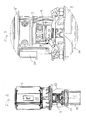
- FIG. 1 Pump unit shown has a multi-stage centrifugal pump 1, whose shaft is not visible in the drawings is perpendicular and exits at the top of the pump housing 2, where it is connected via a coupling 3 with the shaft of an electric motor 4, which is mounted on a motor chair 5 on the Top of the pump housing 2 is flanged.
- the electric motor 4 is a dry runner.
- the pump housing 2 has a base-side foot 6 with two inline connection flanges 7 and 8, one of which the Suction port and the other forms the pressure port of the pump 1.
- the individual pump stages are arranged within a stainless steel jacket, which extends between the foot 6 and an upper housing part 9, which also forms the motor chair 5.
- the housing parts 6 and 9 are clamped together in the usual way via tie rods 10.
- the mechanical seals are arranged in a cartridge-like housing 11, the so-called slide ring cartridge and correspond to the built-in example in the CR series Grundfos conventional seal cartridges, with which the pump shaft is sealed against the pump housing 2.
- a container 12 which is formed as an annular, upwardly open and lockable by a cover 13 housing.
- the container 12 has on its underside two concentric arranged in different planes grooves 14 and 15, which are directed downwards and are provided for receiving in each case an O-ring.
- This groove 18 has an installation opening in an obliquely downwardly extending drain opening 19, in which a sensor 20 is incorporated, which is formed from two metallic tubes 21 and 22, which are electrically insulated from each other.
- the inner tube 21 and the outer tube 22 form electrical contacts, which are connected via an electrical cable 23 to a arranged in an electronics housing 24 evaluation electronics.
- the outer tube 22 projects obliquely downwards and outwards, so that liquid emerging therefrom passes into the side region of the pump housing.
- the electronics housing 24 is rotationally offset from the sensor 20 and mounted below the motor chair 5 within the upper housing part 9. From the electronics housing 24 lead from electrical connections, not shown, to the control electronics of the engine, which is arranged in the illustrated embodiment in a terminal box 25 which receives an electronic speed controller of the engine and the control electronics for it.
- the evaluation electronics so that when using this arrangement, it is firstly possible to reliably detect whether the shaft seal is leak-tight or allows fluid to pass through. If it lets fluid through it can be further detected, how much liquid this is. Small amounts will only be single drops, and the approximate amount can be determined by the time interval between the overflowing drops.
- the electrical connection between the inner tube 21 and the outer tube 22 is permanently short-circuited by liquid, which is also registrable.
- the sensor can be refined, so that at least a coarse flow rate can be determined in a trickle formation. This is done by the distance between the inner and outer tube is further increased, the larger it is, the greater must be the passing amount of water, which causes a permanent short circuit between the pipes. In this way, the sensor can be refined in terms of its quantitative measurement properties.
Landscapes
- Engineering & Computer Science (AREA)
- Mechanical Engineering (AREA)
- General Engineering & Computer Science (AREA)
- Structures Of Non-Positive Displacement Pumps (AREA)
Abstract
Description
- Die Erfindung betrifft eine Kreiselpumpe, insbesondere eine mehrstufige Kreiselpumpe, die zum Antrieb mittels eines als Trockenläufer ausgebildeten Motors vorgesehen ist, der über eine Kupplung mit der die Pumpe antreibenden Welle verbunden ist.
- Kreiselpumpen weisen mindestens ein Laufrad auf, das drehfest auf einer Welle angeordnet ist, die mittels mindestens einer Dichtung zu einem umgebenden Gehäuse hin abgedichtet ist. Insbesondere bei den vorerwähnten mehrstufigen Kreiselpumpen wird die aus dem Pumpengehäuse einseitig austretende Antriebswelle mit einer Gleitringdichtung abgedichtet, welche ein Austreten der innerhalb des Gehäuses befindlichen Flüssigkeit längs der Außenseite der Welle verhindern soll. Insbesondere bei mehrstufigen Pumpen ist der Druck in diesem Bereich des Gehäuses vergleichsweise hoch, sodass eine vollständige Dichtigkeit nur aufwändig realisierbar ist. Je höher der Anpressdruck der Dichtung angesetzt wird, desto weniger Flüssigkeit kann durch den Dichtspalt austreten. Allerdings wachsen mit kleiner werdendem Dichtspalt die Reibungskräfte, die vom Antrieb zusätzlich aufgebracht werden müssen, die ausschließlich in Wärme umgesetzt werden und die den Wirkungsgrad verschlechtern. Auch geht mit zunehmender Reibung Verschleiß einher, der die Standzeit der Dichtung negativ beeinflusst. Vor diesem Hintergrund hat es sich gezeigt, dass bei zahlreichen Anwendungen, insbesondere bei denen es um das Pumpen von Wasser geht, es durchaus vorteilhaft sein könnte, einen geringen Flüssigkeitsdurchtritt durch die Dichtung in Kauf zu nehmen, um auf diese Weise die Reibungskräfte gering zu halten und die Standzeit der Dichtung zu erhöhen. Dies setzt allerdings voraus, dass der Durchtritt von Flüssigkeit durch die Dichtung überwacht wird, um sicherzustellen, dass dieser nicht unzulässig hoch wird.
- Vor diesem Hintergrund liegt der Erfindung die Aufgabe zugrunde, eine Kreiselpumpe so auszubilden, dass der Flüssigkeitsdurchtritt im Bereich der Wellendichtung erfasst werden kann.
- Gemäß der Erfindung wird dies bei einer Kreiselpumpe mit den eingangs genannten Merkmalen dadurch gelöst, dass ein zur Dichtung hin offenes Behältnis vorgesehen ist, welches so ausgebildet und angeordnet ist, dass es das durch die Dichtung hindurchtretende Fluid, insbesondere die durch die Dichtung hindurch tretende Flüssigkeit auffängt und das weiterhin Mittel vorgesehen sind, welche die Flüssigkeit in dem Behältnis erfassen oder aus dem Behältnis, d. h. Mittel, die den Flüssigkeitsstand innerhalb des Behältnisses oder den Ausfluss aus dem Behältnis erfassen. Ein zur Dichtung hin offenes Behältnis im Sinne der Erfindung ist ein Behältnis, welches zum Dichtspalt zwischen Dichtung und Welle offen ist, d. h. dass es längs der Welle oder an der Dichtung austretende Flüssigkeit aufnehmen kann.
- Die erfindungsgemäße Kreiselpumpe, welche mindestens ein Laufrad aufweist, welches drehfest auf einer Welle angeordnet ist, die mittels mindestens einer Dichtung zu einem umgebenden Gehäuse hin abgedichtet ist, weist ein im Gehäuse angeordnetes und mindestens zur Dichtung hin offenes Behältnis zum Auffangen von durch die Dichtung hindurchtretenden Fluid auf und ist mit Mitteln zur Erfassung von Flüssigkeit in oder aus dem Behältnis ausgestattet.
- Grundgedanke der vorliegender Erfindung ist es somit, den Flüssigkeitsdurchtritt durch die Dichtung zu erfassen und zu überwachen, was Voraussetzung für einen sicheren Betrieb ist, in welchem der Durchtritt einer gewissen Flüssigkeitsmenge toleriert wird. Dieser Betrieb erst ermöglicht es, die Reibkräfte im Bereich der Dichtung deutlich zu verringern und damit den Wirkungsgrad des Aggregats zu verbessern und weiterhin die Standzeit der Dichtung zu erhöhen. Durch die erfindungsgemäße Anordnung wird das durch die Dichtung durchtretende Fluid, insbesondere in flüssiger Form kontrolliert und somit die Dichtung während ihres Betriebs überwacht. Die erfindungsgemäße Anordnung hat also nicht nur die vorgenannten Vorteile im Betrieb, sondern bietet darüber hinaus auch noch eine zuverlässige Funktionsüberwachung der Dichtung, stellt also frühzeitig fest, wenn die Dichtung oder die Dichtungen verschleißen, bevor diese vollständig versagen. Die erfindungsgemäße Anordnung kann somit nicht nur bei Pumpen Verwendung finden, bei denen ein Flüssigkeitsdurchtritt durch die Dichtung bewusst in Kauf genommen wird, sondern auch bei solchen Pumpen, bei denen dies keinesfalls erwünscht ist. So können nicht nur Gleitringdichtungen sondern auch beliebige andere Dichtungen, beispielsweise O-Ringe auf ihre Dichtigkeit hin überwacht werden.
- Um die durch den Dichtspalt durchtretende Flüssigkeit zuverlässig zu erfassen, ist gemäß einer Weiterbildung der Erfindung das Behältnis ringförmig, die Welle umgebend ausgebildet. Somit kann das am Umfang der Welle oder an der Dichtung durch den Dichtspalt aus dem Pumpengehäuse austretende Fluid in dem ringförmigen Behältnis aufgefangen werden. Dabei besteht die Möglichkeit entweder die im Behältnis befindliche Flüssigkeit hinsichtlich der Menge, also typischerweise der Füllstandshöhe im Behältnis zu erfassen oder aber im Behältnis einen Abfluss vorzusehen und die durch diesen Abfluss durchtretende Flüssigkeit zu erfassen.
- Besonders vorteilhaft wird die Flüssigkeit mittels elektrischer Kontakte erfasst, es sind also mindestens zwei zueinander elektrisch isolierte Kontakte vorgesehen, die durch die Flüssigkeit elektrisch leitend verbunden werden. Eine solche Anordnung ist wenig aufwändig, im Betrieb nicht störanfällig, da keine beweglichen Teile vorhanden und hinsichtlich der Auswertung einfach zu handhaben. Es sind typischerweise zwei Zustände elektronisch zu erfassen, nämlich der Zustand, bei welchem die Kontakte durch Gas, typischerweise die Umgebungsluft, und der Zustand, bei dem die Kontakte durch Flüssigkeit verbunden sind. Die ohmschen Widerstände dieser beiden Zustände unterscheiden sich hinreichend, eine Erfassung im ungefährlichen Niederspannungsbereich ist ohne weiteres möglich, die Auswertelektronik kann weitgehend durch digitale Logikbausteine erfolgen.
- Um einen Flüssigkeitsstand innerhalb des Behältnisses zu erfassen, können gemäß einer Weiterbildung der Erfindung drei oder mehr Kontakte in unterschiedlicher Höhe innerhalb des Behältnisses angeordnet sein, sodass der Flüssigkeitsstand innerhalb des Behältnisses in Stufen erfasst werden kann.
- Vorteilhaft weist das Behältnis eine Ablauföffnung auf, durch welche die im Behältnis befindliche Flüssigkeit gezielt vorzugsweise nach außen abgeleitet wird. Insbesondere bei der Förderung von Wasser ist eine Ableitung geringer Mengen nach außen in der Regel unproblematisch und tolerierbar.
- Besonders vorteilhaft ist es, wenn in oder an der Ablauföffnung ein Sensor zur Erfassung des Durchflusses, insbesondere ein Sensor zur Erfassung von Tropfen angeordnet ist, da damit auf einfache und effektive Weise die Menge der ausfließenden Flüssigkeit erfasst werden kann. Ein solcher Tropfensensor genügt, da bei einer bevorzugten Dichtspaltdimensionierung ein Flüssigkeitsaustritt toleriert wird, welcher bei wenigen Tropfen pro Minute oder pro Stunde liegt.
- Gemäß einer Weiterbildung der Erfindung kann ein solcher Sensor mittels zwei zueinander elektrisch isolierten Kontakten gebildet werden, deren Abstand so dimensioniert ist, dass diese durch einen vorbeilaufenden Flüssigkeitstropfen elektrisch leitend verbunden werden. Hier erfolgt in analoger Weise eine Widerstandsmessung, wie bereits einleitend bei der Füllstandsermittlung beschrieben.
- Als besonders vorteilhaft hat es sich erwiesen, den Sensor durch zwei zueinander elektrisch isolierte aber elektrisch leitende, vorzugsweise metallische Rohre zu bilden, die koaxial ineinander liegen und bei denen das innere Rohr mit Abstand vor dem Ende des äußeren Rohrs endet. Diese Rohre sind in der Ablauföffnung des Behältnisses dicht eingegliedert und vorzugsweise etwa in einem Winkel von 45° zur Vertikalen angeordnet. Sie bestehen typischerweise aus Edelstahl und sind elektrisch leitend mit der Auswertelektronik verbunden. Wenn ein aus dem Behältnis austretender Tropfen in die Ablauföffnung gelangt, läuft dieser zunächst durch das innere Rohr schräg nach unten und außen, bis er am Ende des inneren Rohrs in das äußere Rohr gelangt. Dabei ist der Abstand der Rohre so dimensioniert, dass beim Übertritt des Tropfens ein Kurzschluss zwischen den beiden Rohren bzw. eine elektrische Verbindung durch den Tropfen, also die Flüssigkeit entsteht, die sich von der normalen Luftverbindung widerstandsmäßig unterscheidet und somit detektierbar ist. Mit diesem Sensor kann nicht nur der Trockenzustand und ein durchlaufender Tropfen detektiert werden, sondern auch ein Dauerdurchfluss, d. h. wenn sich ein Rinnsal bildet, welches die Kontakte dauerhaft kurzschließt. Durch die Dimensionierung des Abstandes der Kontakte zueinander kann die Empfindlichkeit des Sensors eingestellt werden. Wenn der Abstand größer als der eines Tropfens ist, dann ist der Sensor nur zur Erfassung von Rinnsalen geeignet, welche die Kontakte dauerhaft kurzschließen.
- Besonders vorteilhaft handelt es sich bei der Kreiselpumpe bzw. dem damit gebildeten Kreiselpumpenaggregat um ein solches, bei dem die Welle senkrecht stehend angeordnet und die Pumpe oben mit einer Gleitringdichtung abgedichtet ist, bei der das Behältnis zwischen Pumpe und Motor angeordnet ist und das Behältnis unten eine Ablauföffnung aufweist, an die der durch Rohre gebildete Sensor anschließt, dessen anderes Ende ins Freie oder in eine Ablaufleitung mündet. Eine solche Ausbildung ist typischerweise bei mehrstufigen Kreiselpumpen vorgesehen, wie sie beispielsweise von der Firma Grundfos in der Typenreihe CR angeboten wird.
- Das Behältnis, welches das durch die Dichtung austretende Fluid auffängt und die Mittel zur Erfassung der Flüssigkeit in oder aus dem Behältnis können insbesondere bei der vorbeschrieben mehrstufigen Pumpe mit wenigen kostengünstig herzustellenden Bauteilen realisiert werden, die Anordnung in einem ohnehin vorhandenen Freiraum ist unproblematisch. Insbesondere für die Verwendung von Gleitringdichtungen ist eine solche Anordnung von Vorteil, da damit eine Dichtungsdimensionierung möglich ist, welche eine gezielte geringe Leckage zulässt, um so die Reibung innerhalb der Dichtung und die Standzeit der Dichtung verbessern zu können.
- Die Anordnung ist allerdings nicht auf Gleitringdichtungen beschränkt und kann in gleicher Weise für eine Überwachung von O-Ringen oder anderen Dichtungen genutzt werden. Dabei weist der erfindungsgemäße Sensor zwei zueinander elektrisch isolierende und leitende Rohre auf, die ineinander liegen und von denen das innere Rohr mit Abstand vor dem Ende des äußeren Rohrs endet. Ein solcher Sensor kann nicht nur an dem vorbeschrieben Behältnis sondern gegebenenfalls auch an anderen Gehäuseteilen vorgesehen werden, um eine Leckage zu erfassen und zwar nicht nur qualitativ sondern auch quantitativ. Der Sensor ist kostengünstig in der Herstellung, robust und arbeitet langzeitstabil. Die Auswertung anhand des sich ändernden Widerstandes beim Überfließen eines Tropfens ist technisch wenig aufwändig und elektronisch einfach zu realisieren.
- Die Erfindung ist nachfolgend anhand eines in der Zeichnung dargestellten Ausführungsbeispiels näher erläutert. Es zeigen:
- Fig. 1
- in vereinfachter perspektivischer Darstellung eine mehrstufige Kreiselpumpe mit angeschlossenem Antriebsmotor,
- Fig. 2
- den oberen Teil des Aggregats gemäß
Fig. 1 in Seitenansicht, - Fig. 3
- die Einzelheit III der
Fig. 2 , - Fig. 4
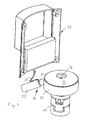
- die Gleitringdichtung mit Behältnis, Sensor und Elektronikeinheit in perspektivischer Darstellung ohne das Pumpenaggregat und
- Fig. 5
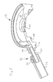
- einen Schnitt durch das Behältnis und den Sensor in der Ablauföffnung.
- Das in
Fig. 1 dargestellte Pumpenaggregat weist eine mehrstufige Kreiselpumpe 1 auf, deren in den Zeichnungen nicht sichtbare Welle senkrecht angeordnet ist und an der Oberseite des Pumpengehäuses 2 austritt, wo sie über eine Kupplung 3 mit der Welle eines Elektromotors 4 verbunden ist, der auf einem Motorstuhl 5 an der Oberseite des Pumpengehäuses 2 angeflanscht ist. Bei dem Elektromotor 4 handelt es sich um einen Trockenläufer. - Das Pumpengehäuse 2 weist einen bodenseitigen Fuß 6 auf mit zwei inline angeordneten Anschlussflanschen 7 und 8, von denen einer den Sauganschluss und der andere den Druckanschluss der Pumpe 1 bildet. Die einzelnen Pumpenstufen sind innerhalb eines Edelstahlmantels angeordnet, der sich zwischen den Fuß 6 und einem oberen Gehäuseteil 9 erstreckt, welches auch den Motorstuhl 5 bildet. Die Gehäuseteile 6 und 9 sind in üblicher Weise über Zuganker 10 miteinander verspannt.
- Im oberen Gehäuseteil 9, welcher den Pumpenkopf bildet und Freiraum für die Kupplung 3 aufweist, ist das aus dem Pumpengehäuse 2 nach oben hin austretende Wellenende mittels Gleitringdichtungen gegenüber dem Pumpengehäuse 2 abgedichtet.
- Die Gleitringdichtungen sind in einem patronenartigen Gehäuse 11, der so genannten Gleitring-Cartridge angeordnet und entsprechen den beispielsweise in der CR-Baureihe von Grundfos verbauten üblichen Dichtungspatronen, mit welcher die Pumpenwelle gegenüber dem Pumpengehäuse 2 abgedichtet wird.
- An das, die Welle umgebende Dichtungsgehäuse 11, welches die Gleitringdichtungen beinhaltet, schließt nach oben ein Behältnis 12 an, welches als ringförmiges, nach oben offenes und mittels eines Deckels 13 abschließbares Gehäuse ausgebildet ist. Das Behältnis 12 weist an seiner Unterseite zwei konzentrische in unterschiedlichen Ebenen angeordnete Nuten 14 und 15 auf, die nach unten gerichtet sind und zur Aufnahme jeweils eines O-Rings vorgesehen sind. Mittels dieser in den Nuten 14 und 15 liegenden O-Ringe wird ein dichter Anschluss an das darunter liegende Dichtungsgehäuse 11 gewährleistet, um sicherzustellen, dass sämtliche, aus dem Dichtspalt im Bereich von Welle und Gleitringdichtung austretende Flüssigkeit in dieses Behältnis 2 geführt wird. Da ein dichter Abschluss der Unterseite des Behältnisses 12 über die in den Nuten 14 und 15 liegenden O-Ringe gegenüber der Oberseite des Dichtungsgehäuses 11 gebildet ist, gelangt die durch den Dichtspalt im Beriech von Welle und Gleitringdichtung austretende Flüssigkeit mit zunehmender Menge längs der Welle durch die zentrale Öffnung 16 bzw. den zwischen der Welle und dieser zentralen Öffnung 16 gebildeten Ringspalt nach oben in das Behältnis 12, wo es über eine von innen nach außen abfallende Ringfläche 17 in eine umlaufende und nach oben offene Nut 18 geführt wird. Diese Nut 18 weist eine in Einbaulage schräg nach unten verlaufende Ablauföffnung 19 auf, in welcher ein Sensor 20 eingegliedert ist, der aus zwei metallischen Rohren 21 und 22 gebildet ist, die zueinander elektrisch isoliert sind. Das innere Rohr 21, welches unmittelbar an die Ablauföffnung 19 anschließt, mündet in ein äußeres Rohr 22, welches das freie Ende des inneren Rohres 21 übergreift und im Freien endet. Das innere Rohr 21 und das äußere Rohr 22 bilden elektrische Kontakte, die über ein elektrisches Kabel 23 mit einer in einem Elektronikgehäuse 24 angeordneten Auswertelektronik verbunden sind. In Einbaulage ragt das äußere Rohr 22 schräg nach unten und außen, sodass daraus austretende Flüssigkeit in den Seitenbereich des Pumpengehäuses gelangt. Das Elektronikgehäuse 24 ist drehversetzt zu dem Sensor 20 angeordnet und unterhalb des Motorstuhles 5 innerhalb des oberen Gehäuseteils 9 befestigt. Vom Elektronikgehäuse 24 aus führen nicht dargestellte elektrische Verbindungen zu der Steuerelektronik des Motors, die in der dargestellten Ausführung in einen Klemmenkasten 25 angeordnet ist, welcher einen elektronischen Drehzahlsteller des Motors und die Steuerelektronik dafür aufnimmt.
- Wenn im Betrieb der Pumpe, also wenn aufgrund des innerhalb der Pumpe erzeugten Drucks Förderflüssigkeit durch die Gleitringdichtungen, d. h. an der Oberseite des Dichtungsgehäuses 11 wellennah austritt, kann diese aufgrund der seitlichen Abdichtungen des Behältnisses 12 im Dichtungsgehäuse 11 seitlich nicht abgeführt werden, sondern steigt bis in das Behältnis 12 auf, wo sie schließlich nach Durchtritt des Behältnisbodens die Ringfläche 17 erreicht und schwerkraftbedingt in die umlaufende Nut 18 fließt. Von dort gelangt die Flüssigkeit dann in die Ablauföffnung 19 und in den Sensor 20. Ein in den Sensor 20 fließender Flüssigkeitstropfen fließt zunächst durch das innere Rohr 21 weiter nach unten und außen bis er vom inneren Rohr 21 in das äußere Rohr 22 übertritt und dabei eine elektrische Verbindung zwischen den beiden Rohren schafft, wodurch sich der Übergangswiderstand von bisher Luft in Förderflüssigkeit ändert. Dies wird durch die Auswertelektronik registriert, sodass bei Verwendung dieser Anordnung es zum einen möglich ist, zuverlässig zu detektieren, ob die Wellendichtung dicht ist oder Flüssigkeit durchlässt. Wenn sie Flüssigkeit durchlässt kann im weiteren detektiert werden, wie viel Flüssigkeit dies ist. Bei geringen Mengen wird es sich nur um einzelne Tropfen handeln, wobei durch den zeitlichen Abstand der überlaufenden Tropfen die ungefähre Menge erfasst werden kann. Sobald sich ein Rinnsal bildet, wird die elektrische Verbindung zwischen dem inneren Rohr 21 und dem äußeren Rohr 22 dauerhaft durch Flüssigkeit kurzgeschlossen, was ebenfalls registrierbar ist. Gegebenenfalls kann durch Anordnung eines weiteren Rohres der Sensor verfeinert werden, sodass bei einer Rinnsalbildung zumindest grob die Durchflussmenge ermittelt werden kann. Dies erfolgt indem der Abstand zwischen inneren und äußerem Rohr weiter vergrößert wird, je größer dieser ist, desto größer muss die durchlaufende Wassermenge, die einen dauerhaften Kurzschluss zwischen den Rohren verursacht, sein. Auf diese Weise kann der Sensor hinsichtlich seiner quantitativen Messeigenschaften verfeinert werden.
- Die vorstehend beschriebene Anordnung ist zwar anhand eines Kreiselpumpenaggregat mit einer mehrstufigen Kreiselpumpe der Inline-Bauart mit senkrecht stehender Welle dargestellt und beschrieben worden, es versteht sich jedoch, dass nach dem erfindungsgemäßen Prinzip bei definierter Lage einer Pumpe mit der erfindungsgemäßen Anordnung an der Pumpe auch eine Vielzahl anderer Pumpenbauarten hinsichtlich der Funktion ihrer Dichtung überwacht werden können.
-
- 1
- Kreiselpumpe
- 2
- Pumpengehäuse
- 3
- Kupplung
- 4
- Elektromotor
- 5
- Motorstuhl
- 6
- Fuß vom Pumpengehäuse
- 7
- Anschlussflansch
- 8
- Anschlussflansch
- 9
- oberes Gehäuseteil
- 10
- Zuganker
- 11
- Dichtungsgehäuse
- 12
- Behältnis
- 13
- Deckel von 12
- 14
- Nut
- 15
- Nut
- 16
- zentrale Öffnung
- 17
- Ringfläche
- 18
- nach oben offene Nut
- 19
- Ablauföffnung
- 20
- Sensor
- 21
- inneres Rohr
- 22
- äußeres Rohr
- 23
- Kabel
- 24
- Elektronikgehäuse
- 25
- Klemmenkasten
Claims (10)
- Kreiselpumpe, insbesondere mehrstufige Kreiselpumpe (1) mit mindestens einem Laufrad, das drehfest auf einer Welle angeordnet ist, welche mittels mindestens einer Dichtung (11) zu einem umgebenden Gehäuse (2) hin abgedichtet ist, mit einem am Gehäuse (2) angeordneten und mindestens zur Dichtung (11) hin offenen Behältnis zum Auffangen von durch die Dichtung (11) hindurchtretendem Fluid und mit Mitteln zur Erfassung von Flüssigkeit im oder aus dem Behältnis (12).
- Kreiselpumpe nach Anspruch 1, bei der das Behältnis (12) ringförmig die Welle umgebend ausgebildet ist.
- Kreiselpumpe nach Anspruch 1 oder 2, bei der die Mittel zur Erfassung von Flüssigkeit mindestens zwei zueinander elektrisch isolierte Kontakte (21, 22) aufweist, die durch die Flüssigkeit elektrisch leitend verbunden werden.
- Kreiselpumpe nach einem der vorhergehenden Ansprüche, bei der innerhalb des Behältnisses (12) drei oder mehr Kontakte in unterschiedlicher Höhe angeordnet sind.
- Kreiselpumpe nach einem der vorhergehenden Ansprüche, bei der das Behältnis (12) eine Ablauföffnung (19) nach außen aufweist.
- Kreiselpumpe nach einem der vorhergehenden Ansprüche, bei der an der Ablauföffnung (19) ein Sensor (20) zur Erfassung des Durchflusses, insbesondere ein Sensor (20) zur Erfassung von Tropfen angeordnet ist.
- Kreiselpumpe nach einem der vorhergehenden Ansprüche, bei der der Sensor (20) zwei zueinander elektrisch isolierte Kontakte (21, 22) aufweist, deren Abstand so dimensioniert ist, dass diese durch einen vorbeilaufenden Flüssigkeitstropfen elektrisch leitend verbunden werden.
- Kreiselpumpe nach einem der vorhergehenden Ansprüche, bei der der Sensor (20) durch zwei zueinander elektrisch isolierte und elektrisch leitende vorzugsweise metallische Rohre (21, 22) gebildet ist, die koaxial ineinander liegen, wobei das innere Rohr (21) mit Abstand vor dem Ende des äußeren Rohres (22) endet.
- Kreiselpumpe nach einem der vorhergehenden Ansprüche, bei der die Welle senkrecht stehend angeordnet und die Pumpe oben mit einer Gleitringdichtung (11) abgedichtet ist, bei der das Behältnis (12) zwischen Pumpe (1) und einem diese antreibenden Motor (4) angeordnet ist und unten eine Ablauföffnung (19) aufweist, an die der durch Rohre (21, 22) gebildete Sensor (20) anschließt, dessen anderes Ende ins Freie oder in eine Ablaufleitung mündet.
- Sensor, insbesondere für eine Kreiselpumpe nach einem der vorhergehenden Ansprüche, der zwei zueinander elektrisch isolierte und leitende Rohre (21, 22) aufweist, die ineinander liegen und von denen das innere Rohr (21) mit Abstand vor dem Ende des äußeren Rohrs (22) endet.
Priority Applications (2)
| Application Number | Priority Date | Filing Date | Title |
|---|---|---|---|
| EP12170230.2A EP2669525B1 (de) | 2012-05-31 | 2012-05-31 | Kreiselpumpenaggregat |
| PCT/EP2013/059581 WO2013178444A1 (de) | 2012-05-31 | 2013-05-08 | Kreiselpumpe |
Applications Claiming Priority (1)
| Application Number | Priority Date | Filing Date | Title |
|---|---|---|---|
| EP12170230.2A EP2669525B1 (de) | 2012-05-31 | 2012-05-31 | Kreiselpumpenaggregat |
Publications (2)
| Publication Number | Publication Date |
|---|---|
| EP2669525A1 true EP2669525A1 (de) | 2013-12-04 |
| EP2669525B1 EP2669525B1 (de) | 2018-01-24 |
Family
ID=48468258
Family Applications (1)
| Application Number | Title | Priority Date | Filing Date |
|---|---|---|---|
| EP12170230.2A Active EP2669525B1 (de) | 2012-05-31 | 2012-05-31 | Kreiselpumpenaggregat |
Country Status (2)
| Country | Link |
|---|---|
| EP (1) | EP2669525B1 (de) |
| WO (1) | WO2013178444A1 (de) |
Cited By (2)
| Publication number | Priority date | Publication date | Assignee | Title |
|---|---|---|---|---|
| US20190086286A1 (en) * | 2017-09-20 | 2019-03-21 | Grundfos Holding A/S | Pump seal leakage detection system |
| US11054333B2 (en) * | 2019-03-15 | 2021-07-06 | Caterpillar Inc. | Device for detecting an oil leak |
Families Citing this family (1)
| Publication number | Priority date | Publication date | Assignee | Title |
|---|---|---|---|---|
| DE102016202892A1 (de) * | 2016-02-24 | 2017-08-24 | Thyssenkrupp Ag | Vorrichtung zum Abdichten einer Pumpe sowie Pumpenabdichtsystem und Verwendung einer Stopfbuchse in der Vorrichtung |
Citations (10)
| Publication number | Priority date | Publication date | Assignee | Title |
|---|---|---|---|---|
| GB943685A (en) * | 1961-07-11 | 1963-12-04 | Donald Watkins | Improvements relating to connecting and sealing means between electric motors and pumping units |
| GB965524A (en) * | 1962-06-23 | 1964-07-29 | Blum Albert | Improvements in immersible pumps |
| FR1507108A (fr) * | 1966-01-03 | 1967-12-22 | Moto-pompe électrique immergée | |
| GB1314651A (en) * | 1970-03-24 | 1973-04-26 | Blum A | Submersible electric motor-pump assemblages |
| EP0341368A1 (de) * | 1988-05-10 | 1989-11-15 | ABS Pumpen AG | Tauchmotorpumpe |
| DE4002245A1 (de) * | 1990-01-26 | 1991-08-22 | Werner Dipl Ing Arnswald | Tauchmotorpumpe |
| US5173019A (en) * | 1991-08-05 | 1992-12-22 | American Gage And Machine Company | Pump including secondary containment with alarm system |
| DE19711185A1 (de) * | 1997-03-18 | 1998-09-24 | Werner Dipl Ing Arnswald | Tauchmotorpumpe |
| US6364620B1 (en) * | 2000-08-29 | 2002-04-02 | Zoeller Company | Submersible pump containing two levels of moisture sensors |
| US6422822B1 (en) * | 2000-06-15 | 2002-07-23 | Shell Oil Company | Pressurized seal for submersible pumps |
-
2012
- 2012-05-31 EP EP12170230.2A patent/EP2669525B1/de active Active
-
2013
- 2013-05-08 WO PCT/EP2013/059581 patent/WO2013178444A1/de not_active Ceased
Patent Citations (10)
| Publication number | Priority date | Publication date | Assignee | Title |
|---|---|---|---|---|
| GB943685A (en) * | 1961-07-11 | 1963-12-04 | Donald Watkins | Improvements relating to connecting and sealing means between electric motors and pumping units |
| GB965524A (en) * | 1962-06-23 | 1964-07-29 | Blum Albert | Improvements in immersible pumps |
| FR1507108A (fr) * | 1966-01-03 | 1967-12-22 | Moto-pompe électrique immergée | |
| GB1314651A (en) * | 1970-03-24 | 1973-04-26 | Blum A | Submersible electric motor-pump assemblages |
| EP0341368A1 (de) * | 1988-05-10 | 1989-11-15 | ABS Pumpen AG | Tauchmotorpumpe |
| DE4002245A1 (de) * | 1990-01-26 | 1991-08-22 | Werner Dipl Ing Arnswald | Tauchmotorpumpe |
| US5173019A (en) * | 1991-08-05 | 1992-12-22 | American Gage And Machine Company | Pump including secondary containment with alarm system |
| DE19711185A1 (de) * | 1997-03-18 | 1998-09-24 | Werner Dipl Ing Arnswald | Tauchmotorpumpe |
| US6422822B1 (en) * | 2000-06-15 | 2002-07-23 | Shell Oil Company | Pressurized seal for submersible pumps |
| US6364620B1 (en) * | 2000-08-29 | 2002-04-02 | Zoeller Company | Submersible pump containing two levels of moisture sensors |
Cited By (5)
| Publication number | Priority date | Publication date | Assignee | Title |
|---|---|---|---|---|
| US20190086286A1 (en) * | 2017-09-20 | 2019-03-21 | Grundfos Holding A/S | Pump seal leakage detection system |
| CN109519394A (zh) * | 2017-09-20 | 2019-03-26 | 格兰富控股联合股份公司 | 泵密封件泄漏检测系统 |
| EP3460440A1 (de) | 2017-09-20 | 2019-03-27 | Grundfos Holding A/S | Pumpendichtungleckagedetektionssystem |
| US10948375B2 (en) | 2017-09-20 | 2021-03-16 | Grundfos Holding A/S | Pump seal leakage detection system |
| US11054333B2 (en) * | 2019-03-15 | 2021-07-06 | Caterpillar Inc. | Device for detecting an oil leak |
Also Published As
| Publication number | Publication date |
|---|---|
| WO2013178444A1 (de) | 2013-12-05 |
| EP2669525B1 (de) | 2018-01-24 |
Similar Documents
| Publication | Publication Date | Title |
|---|---|---|
| EP3174613B1 (de) | Wasserabscheideelement mit wasserdetektionselektroden | |
| DE102007017271A1 (de) | Pumpe mit Heizeinrichtung | |
| WO2016146226A1 (de) | Filtervorrichtung | |
| EP2445605B1 (de) | Filtereinrichtung | |
| DE102004011365A1 (de) | Kreiselpumpe | |
| WO2007090379A1 (de) | Fluidfilter, mit geschütztem flüssigkeitssensor | |
| DE10306873B4 (de) | Wasserzähler mit nach aussen gedichtetem Messeinsatz | |
| EP2669525B1 (de) | Kreiselpumpenaggregat | |
| DE3328484A1 (de) | Pumpe, insbesondere fass- oder tauchpumpe | |
| DE102010005459A1 (de) | Absperrarmatur | |
| EP3403708B1 (de) | Filtersystem mit zentralelement und siebfilter | |
| DE2305743C2 (de) | Strömungsmittelzähler | |
| DE202015103322U1 (de) | Vorsatzstück für Ablauftrichter | |
| DE10101099B4 (de) | Verfahren zum Überwachen des Trockenlaufs einer Förderpumpe und nach dem Verfahren arbeitende Förderpumpe | |
| DE3838931A1 (de) | Elektronischer kalkschutzfilter | |
| WO2017108032A1 (de) | Verbundwasserzähler | |
| EP0439697B1 (de) | Kondensatableiter mit Überwachungseinrichtung | |
| EP1625375B1 (de) | Überwachungseinrichtung für flüssigkeitsführende systeme | |
| DE3540025A1 (de) | Abdichtung fuer eine rotierende, im betrieb aufrecht stehende welle, insbesondere fuer wellen von pumpen und ruehrern | |
| DE10064708A1 (de) | Hauswasserwerk | |
| DE9115728U1 (de) | Meßeinheit für Durchflußzähler für Flüssigkeiten | |
| EP2573284B1 (de) | Abwasserhebeanlage | |
| DE102012222903B4 (de) | Zentrifugalpumpe | |
| DE102011015090A1 (de) | Filter | |
| EP1288501B1 (de) | Drucksensor für eine Tauchpumpe |
Legal Events
| Date | Code | Title | Description |
|---|---|---|---|
| PUAI | Public reference made under article 153(3) epc to a published international application that has entered the european phase |
Free format text: ORIGINAL CODE: 0009012 |
|
| AK | Designated contracting states |
Kind code of ref document: A1 Designated state(s): AL AT BE BG CH CY CZ DE DK EE ES FI FR GB GR HR HU IE IS IT LI LT LU LV MC MK MT NL NO PL PT RO RS SE SI SK SM TR |
|
| AX | Request for extension of the european patent |
Extension state: BA ME |
|
| 17P | Request for examination filed |
Effective date: 20140602 |
|
| RBV | Designated contracting states (corrected) |
Designated state(s): AL AT BE BG CH CY CZ DE DK EE ES FI FR GB GR HR HU IE IS IT LI LT LU LV MC MK MT NL NO PL PT RO RS SE SI SK SM TR |
|
| GRAP | Despatch of communication of intention to grant a patent |
Free format text: ORIGINAL CODE: EPIDOSNIGR1 |
|
| STAA | Information on the status of an ep patent application or granted ep patent |
Free format text: STATUS: GRANT OF PATENT IS INTENDED |
|
| INTG | Intention to grant announced |
Effective date: 20170816 |
|
| GRAS | Grant fee paid |
Free format text: ORIGINAL CODE: EPIDOSNIGR3 |
|
| GRAA | (expected) grant |
Free format text: ORIGINAL CODE: 0009210 |
|
| STAA | Information on the status of an ep patent application or granted ep patent |
Free format text: STATUS: THE PATENT HAS BEEN GRANTED |
|
| AK | Designated contracting states |
Kind code of ref document: B1 Designated state(s): AL AT BE BG CH CY CZ DE DK EE ES FI FR GB GR HR HU IE IS IT LI LT LU LV MC MK MT NL NO PL PT RO RS SE SI SK SM TR |
|
| REG | Reference to a national code |
Ref country code: GB Ref legal event code: FG4D Free format text: NOT ENGLISH |
|
| REG | Reference to a national code |
Ref country code: CH Ref legal event code: EP |
|
| REG | Reference to a national code |
Ref country code: AT Ref legal event code: REF Ref document number: 965945 Country of ref document: AT Kind code of ref document: T Effective date: 20180215 |
|
| REG | Reference to a national code |
Ref country code: IE Ref legal event code: FG4D Free format text: LANGUAGE OF EP DOCUMENT: GERMAN |
|
| REG | Reference to a national code |
Ref country code: DE Ref legal event code: R096 Ref document number: 502012012057 Country of ref document: DE |
|
| REG | Reference to a national code |
Ref country code: FR Ref legal event code: PLFP Year of fee payment: 7 |
|
| REG | Reference to a national code |
Ref country code: NL Ref legal event code: MP Effective date: 20180124 |
|
| REG | Reference to a national code |
Ref country code: LT Ref legal event code: MG4D |
|
| PG25 | Lapsed in a contracting state [announced via postgrant information from national office to epo] |
Ref country code: NL Free format text: LAPSE BECAUSE OF FAILURE TO SUBMIT A TRANSLATION OF THE DESCRIPTION OR TO PAY THE FEE WITHIN THE PRESCRIBED TIME-LIMIT Effective date: 20180124 |
|
| PG25 | Lapsed in a contracting state [announced via postgrant information from national office to epo] |
Ref country code: LT Free format text: LAPSE BECAUSE OF FAILURE TO SUBMIT A TRANSLATION OF THE DESCRIPTION OR TO PAY THE FEE WITHIN THE PRESCRIBED TIME-LIMIT Effective date: 20180124 Ref country code: FI Free format text: LAPSE BECAUSE OF FAILURE TO SUBMIT A TRANSLATION OF THE DESCRIPTION OR TO PAY THE FEE WITHIN THE PRESCRIBED TIME-LIMIT Effective date: 20180124 Ref country code: NO Free format text: LAPSE BECAUSE OF FAILURE TO SUBMIT A TRANSLATION OF THE DESCRIPTION OR TO PAY THE FEE WITHIN THE PRESCRIBED TIME-LIMIT Effective date: 20180424 Ref country code: HR Free format text: LAPSE BECAUSE OF FAILURE TO SUBMIT A TRANSLATION OF THE DESCRIPTION OR TO PAY THE FEE WITHIN THE PRESCRIBED TIME-LIMIT Effective date: 20180124 Ref country code: ES Free format text: LAPSE BECAUSE OF FAILURE TO SUBMIT A TRANSLATION OF THE DESCRIPTION OR TO PAY THE FEE WITHIN THE PRESCRIBED TIME-LIMIT Effective date: 20180124 Ref country code: CY Free format text: LAPSE BECAUSE OF FAILURE TO SUBMIT A TRANSLATION OF THE DESCRIPTION OR TO PAY THE FEE WITHIN THE PRESCRIBED TIME-LIMIT Effective date: 20180124 |
|
| PG25 | Lapsed in a contracting state [announced via postgrant information from national office to epo] |
Ref country code: PL Free format text: LAPSE BECAUSE OF FAILURE TO SUBMIT A TRANSLATION OF THE DESCRIPTION OR TO PAY THE FEE WITHIN THE PRESCRIBED TIME-LIMIT Effective date: 20180124 Ref country code: RS Free format text: LAPSE BECAUSE OF FAILURE TO SUBMIT A TRANSLATION OF THE DESCRIPTION OR TO PAY THE FEE WITHIN THE PRESCRIBED TIME-LIMIT Effective date: 20180124 Ref country code: SE Free format text: LAPSE BECAUSE OF FAILURE TO SUBMIT A TRANSLATION OF THE DESCRIPTION OR TO PAY THE FEE WITHIN THE PRESCRIBED TIME-LIMIT Effective date: 20180124 Ref country code: LV Free format text: LAPSE BECAUSE OF FAILURE TO SUBMIT A TRANSLATION OF THE DESCRIPTION OR TO PAY THE FEE WITHIN THE PRESCRIBED TIME-LIMIT Effective date: 20180124 Ref country code: GR Free format text: LAPSE BECAUSE OF FAILURE TO SUBMIT A TRANSLATION OF THE DESCRIPTION OR TO PAY THE FEE WITHIN THE PRESCRIBED TIME-LIMIT Effective date: 20180425 Ref country code: IS Free format text: LAPSE BECAUSE OF FAILURE TO SUBMIT A TRANSLATION OF THE DESCRIPTION OR TO PAY THE FEE WITHIN THE PRESCRIBED TIME-LIMIT Effective date: 20180524 Ref country code: BG Free format text: LAPSE BECAUSE OF FAILURE TO SUBMIT A TRANSLATION OF THE DESCRIPTION OR TO PAY THE FEE WITHIN THE PRESCRIBED TIME-LIMIT Effective date: 20180424 |
|
| PG25 | Lapsed in a contracting state [announced via postgrant information from national office to epo] |
Ref country code: MT Free format text: LAPSE BECAUSE OF FAILURE TO SUBMIT A TRANSLATION OF THE DESCRIPTION OR TO PAY THE FEE WITHIN THE PRESCRIBED TIME-LIMIT Effective date: 20180124 |
|
| REG | Reference to a national code |
Ref country code: DE Ref legal event code: R097 Ref document number: 502012012057 Country of ref document: DE |
|
| PG25 | Lapsed in a contracting state [announced via postgrant information from national office to epo] |
Ref country code: EE Free format text: LAPSE BECAUSE OF FAILURE TO SUBMIT A TRANSLATION OF THE DESCRIPTION OR TO PAY THE FEE WITHIN THE PRESCRIBED TIME-LIMIT Effective date: 20180124 Ref country code: AL Free format text: LAPSE BECAUSE OF FAILURE TO SUBMIT A TRANSLATION OF THE DESCRIPTION OR TO PAY THE FEE WITHIN THE PRESCRIBED TIME-LIMIT Effective date: 20180124 Ref country code: RO Free format text: LAPSE BECAUSE OF FAILURE TO SUBMIT A TRANSLATION OF THE DESCRIPTION OR TO PAY THE FEE WITHIN THE PRESCRIBED TIME-LIMIT Effective date: 20180124 |
|
| PG25 | Lapsed in a contracting state [announced via postgrant information from national office to epo] |
Ref country code: SK Free format text: LAPSE BECAUSE OF FAILURE TO SUBMIT A TRANSLATION OF THE DESCRIPTION OR TO PAY THE FEE WITHIN THE PRESCRIBED TIME-LIMIT Effective date: 20180124 Ref country code: CZ Free format text: LAPSE BECAUSE OF FAILURE TO SUBMIT A TRANSLATION OF THE DESCRIPTION OR TO PAY THE FEE WITHIN THE PRESCRIBED TIME-LIMIT Effective date: 20180124 Ref country code: SM Free format text: LAPSE BECAUSE OF FAILURE TO SUBMIT A TRANSLATION OF THE DESCRIPTION OR TO PAY THE FEE WITHIN THE PRESCRIBED TIME-LIMIT Effective date: 20180124 Ref country code: DK Free format text: LAPSE BECAUSE OF FAILURE TO SUBMIT A TRANSLATION OF THE DESCRIPTION OR TO PAY THE FEE WITHIN THE PRESCRIBED TIME-LIMIT Effective date: 20180124 |
|
| PLBE | No opposition filed within time limit |
Free format text: ORIGINAL CODE: 0009261 |
|
| STAA | Information on the status of an ep patent application or granted ep patent |
Free format text: STATUS: NO OPPOSITION FILED WITHIN TIME LIMIT |
|
| REG | Reference to a national code |
Ref country code: CH Ref legal event code: PL |
|
| 26N | No opposition filed |
Effective date: 20181025 |
|
| REG | Reference to a national code |
Ref country code: BE Ref legal event code: MM Effective date: 20180531 |
|
| PG25 | Lapsed in a contracting state [announced via postgrant information from national office to epo] |
Ref country code: MC Free format text: LAPSE BECAUSE OF FAILURE TO SUBMIT A TRANSLATION OF THE DESCRIPTION OR TO PAY THE FEE WITHIN THE PRESCRIBED TIME-LIMIT Effective date: 20180124 |
|
| PG25 | Lapsed in a contracting state [announced via postgrant information from national office to epo] |
Ref country code: LI Free format text: LAPSE BECAUSE OF NON-PAYMENT OF DUE FEES Effective date: 20180531 Ref country code: SI Free format text: LAPSE BECAUSE OF FAILURE TO SUBMIT A TRANSLATION OF THE DESCRIPTION OR TO PAY THE FEE WITHIN THE PRESCRIBED TIME-LIMIT Effective date: 20180124 Ref country code: CH Free format text: LAPSE BECAUSE OF NON-PAYMENT OF DUE FEES Effective date: 20180531 |
|
| REG | Reference to a national code |
Ref country code: IE Ref legal event code: MM4A |
|
| PG25 | Lapsed in a contracting state [announced via postgrant information from national office to epo] |
Ref country code: LU Free format text: LAPSE BECAUSE OF NON-PAYMENT OF DUE FEES Effective date: 20180531 |
|
| PG25 | Lapsed in a contracting state [announced via postgrant information from national office to epo] |
Ref country code: IE Free format text: LAPSE BECAUSE OF NON-PAYMENT OF DUE FEES Effective date: 20180531 |
|
| PG25 | Lapsed in a contracting state [announced via postgrant information from national office to epo] |
Ref country code: BE Free format text: LAPSE BECAUSE OF NON-PAYMENT OF DUE FEES Effective date: 20180531 |
|
| REG | Reference to a national code |
Ref country code: AT Ref legal event code: MM01 Ref document number: 965945 Country of ref document: AT Kind code of ref document: T Effective date: 20180531 |
|
| PG25 | Lapsed in a contracting state [announced via postgrant information from national office to epo] |
Ref country code: AT Free format text: LAPSE BECAUSE OF NON-PAYMENT OF DUE FEES Effective date: 20180531 |
|
| PG25 | Lapsed in a contracting state [announced via postgrant information from national office to epo] |
Ref country code: TR Free format text: LAPSE BECAUSE OF FAILURE TO SUBMIT A TRANSLATION OF THE DESCRIPTION OR TO PAY THE FEE WITHIN THE PRESCRIBED TIME-LIMIT Effective date: 20180124 |
|
| PG25 | Lapsed in a contracting state [announced via postgrant information from national office to epo] |
Ref country code: PT Free format text: LAPSE BECAUSE OF FAILURE TO SUBMIT A TRANSLATION OF THE DESCRIPTION OR TO PAY THE FEE WITHIN THE PRESCRIBED TIME-LIMIT Effective date: 20180124 Ref country code: HU Free format text: LAPSE BECAUSE OF FAILURE TO SUBMIT A TRANSLATION OF THE DESCRIPTION OR TO PAY THE FEE WITHIN THE PRESCRIBED TIME-LIMIT; INVALID AB INITIO Effective date: 20120531 |
|
| PG25 | Lapsed in a contracting state [announced via postgrant information from national office to epo] |
Ref country code: MK Free format text: LAPSE BECAUSE OF NON-PAYMENT OF DUE FEES Effective date: 20180124 |
|
| REG | Reference to a national code |
Ref country code: DE Ref legal event code: R082 Ref document number: 502012012057 Country of ref document: DE |
|
| PGFP | Annual fee paid to national office [announced via postgrant information from national office to epo] |
Ref country code: DE Payment date: 20250521 Year of fee payment: 14 |
|
| PGFP | Annual fee paid to national office [announced via postgrant information from national office to epo] |
Ref country code: GB Payment date: 20250521 Year of fee payment: 14 |
|
| PGFP | Annual fee paid to national office [announced via postgrant information from national office to epo] |
Ref country code: IT Payment date: 20250527 Year of fee payment: 14 |
|
| PGFP | Annual fee paid to national office [announced via postgrant information from national office to epo] |
Ref country code: FR Payment date: 20250528 Year of fee payment: 14 |