EP2669451A2 - Support structure and method for assembling a support structure - Google Patents
Support structure and method for assembling a support structure Download PDFInfo
- Publication number
- EP2669451A2 EP2669451A2 EP13168233.8A EP13168233A EP2669451A2 EP 2669451 A2 EP2669451 A2 EP 2669451A2 EP 13168233 A EP13168233 A EP 13168233A EP 2669451 A2 EP2669451 A2 EP 2669451A2
- Authority
- EP
- European Patent Office
- Prior art keywords
- posts
- support
- fixed
- holder
- supporting structure
- Prior art date
- Legal status (The legal status is an assumption and is not a legal conclusion. Google has not performed a legal analysis and makes no representation as to the accuracy of the status listed.)
- Withdrawn
Links
Images
Classifications
-
- E—FIXED CONSTRUCTIONS
- E04—BUILDING
- E04H—BUILDINGS OR LIKE STRUCTURES FOR PARTICULAR PURPOSES; SWIMMING OR SPLASH BATHS OR POOLS; MASTS; FENCING; TENTS OR CANOPIES, IN GENERAL
- E04H6/00—Buildings for parking cars, rolling-stock, aircraft, vessels or like vehicles, e.g. garages
- E04H6/02—Small garages, e.g. for one or two cars
- E04H6/025—Small garages, e.g. for one or two cars in the form of an overhead canopy, e.g. carports
-
- F—MECHANICAL ENGINEERING; LIGHTING; HEATING; WEAPONS; BLASTING
- F24—HEATING; RANGES; VENTILATING
- F24S—SOLAR HEAT COLLECTORS; SOLAR HEAT SYSTEMS
- F24S25/00—Arrangement of stationary mountings or supports for solar heat collector modules
- F24S25/10—Arrangement of stationary mountings or supports for solar heat collector modules extending in directions away from a supporting surface
- F24S25/13—Profile arrangements, e.g. trusses
-
- H—ELECTRICITY
- H02—GENERATION; CONVERSION OR DISTRIBUTION OF ELECTRIC POWER
- H02S—GENERATION OF ELECTRIC POWER BY CONVERSION OF INFRARED RADIATION, VISIBLE LIGHT OR ULTRAVIOLET LIGHT, e.g. USING PHOTOVOLTAIC [PV] MODULES
- H02S20/00—Supporting structures for PV modules
-
- F—MECHANICAL ENGINEERING; LIGHTING; HEATING; WEAPONS; BLASTING
- F24—HEATING; RANGES; VENTILATING
- F24S—SOLAR HEAT COLLECTORS; SOLAR HEAT SYSTEMS
- F24S25/00—Arrangement of stationary mountings or supports for solar heat collector modules
- F24S2025/80—Special profiles
- F24S2025/801—Special profiles having hollow parts with closed cross-section
-
- F—MECHANICAL ENGINEERING; LIGHTING; HEATING; WEAPONS; BLASTING
- F24—HEATING; RANGES; VENTILATING
- F24S—SOLAR HEAT COLLECTORS; SOLAR HEAT SYSTEMS
- F24S25/00—Arrangement of stationary mountings or supports for solar heat collector modules
- F24S2025/80—Special profiles
- F24S2025/807—Special profiles having undercut grooves
-
- Y—GENERAL TAGGING OF NEW TECHNOLOGICAL DEVELOPMENTS; GENERAL TAGGING OF CROSS-SECTIONAL TECHNOLOGIES SPANNING OVER SEVERAL SECTIONS OF THE IPC; TECHNICAL SUBJECTS COVERED BY FORMER USPC CROSS-REFERENCE ART COLLECTIONS [XRACs] AND DIGESTS
- Y02—TECHNOLOGIES OR APPLICATIONS FOR MITIGATION OR ADAPTATION AGAINST CLIMATE CHANGE
- Y02B—CLIMATE CHANGE MITIGATION TECHNOLOGIES RELATED TO BUILDINGS, e.g. HOUSING, HOUSE APPLIANCES OR RELATED END-USER APPLICATIONS
- Y02B10/00—Integration of renewable energy sources in buildings
- Y02B10/10—Photovoltaic [PV]
-
- Y—GENERAL TAGGING OF NEW TECHNOLOGICAL DEVELOPMENTS; GENERAL TAGGING OF CROSS-SECTIONAL TECHNOLOGIES SPANNING OVER SEVERAL SECTIONS OF THE IPC; TECHNICAL SUBJECTS COVERED BY FORMER USPC CROSS-REFERENCE ART COLLECTIONS [XRACs] AND DIGESTS
- Y02—TECHNOLOGIES OR APPLICATIONS FOR MITIGATION OR ADAPTATION AGAINST CLIMATE CHANGE
- Y02B—CLIMATE CHANGE MITIGATION TECHNOLOGIES RELATED TO BUILDINGS, e.g. HOUSING, HOUSE APPLIANCES OR RELATED END-USER APPLICATIONS
- Y02B10/00—Integration of renewable energy sources in buildings
- Y02B10/20—Solar thermal
-
- Y—GENERAL TAGGING OF NEW TECHNOLOGICAL DEVELOPMENTS; GENERAL TAGGING OF CROSS-SECTIONAL TECHNOLOGIES SPANNING OVER SEVERAL SECTIONS OF THE IPC; TECHNICAL SUBJECTS COVERED BY FORMER USPC CROSS-REFERENCE ART COLLECTIONS [XRACs] AND DIGESTS
- Y02—TECHNOLOGIES OR APPLICATIONS FOR MITIGATION OR ADAPTATION AGAINST CLIMATE CHANGE
- Y02E—REDUCTION OF GREENHOUSE GAS [GHG] EMISSIONS, RELATED TO ENERGY GENERATION, TRANSMISSION OR DISTRIBUTION
- Y02E10/00—Energy generation through renewable energy sources
- Y02E10/40—Solar thermal energy, e.g. solar towers
- Y02E10/47—Mountings or tracking
-
- Y—GENERAL TAGGING OF NEW TECHNOLOGICAL DEVELOPMENTS; GENERAL TAGGING OF CROSS-SECTIONAL TECHNOLOGIES SPANNING OVER SEVERAL SECTIONS OF THE IPC; TECHNICAL SUBJECTS COVERED BY FORMER USPC CROSS-REFERENCE ART COLLECTIONS [XRACs] AND DIGESTS
- Y02—TECHNOLOGIES OR APPLICATIONS FOR MITIGATION OR ADAPTATION AGAINST CLIMATE CHANGE
- Y02E—REDUCTION OF GREENHOUSE GAS [GHG] EMISSIONS, RELATED TO ENERGY GENERATION, TRANSMISSION OR DISTRIBUTION
- Y02E10/00—Energy generation through renewable energy sources
- Y02E10/50—Photovoltaic [PV] energy
Definitions
- the present invention relates to a support structure according to the preamble of claim 1 and a method for mounting a support structure.
- the DE 20 2009 006 182 discloses a shelter in which four supports with VV-shaped arrangement are fixed to a base. At the upper end of the four inclined supports a support is mounted, on which a roof is mounted.
- the arrangement of four diagonal supports on a pedestal is statically disadvantageous especially for longer carriers.
- the assembly is complicated, since the heavy support must be mounted from above on the diagonal struts, which makes it necessary to use lifting devices for heavy parts on site.
- it can come to significant thermal stresses due to the rigid definition of the carrier on the diagonal supports.
- a support beam is received at opposite ends on or in a holder and is rotatably mounted in a mounting position about a horizontal axis on a post to then be fixed after alignment of the support beam to the post.
- This makes it possible to mount the support beam from below to the holder, which is then pivoted about a horizontal axis and fixed to the post.
- This allows mounting of the support beams without heavy lifting equipment, which must be laboriously transported to the site. Depending on the length of the support beam, this can even be set manually on or in the holder.
- a self-teaching alignment of the posts and the holder is possible.
- the holders have a U-shaped receptacle into which an end portion of a supporting beam can be inserted.
- the U-shaped receptacle in a mounting position, can be opened downwards in order to insert the support bar, which is then pre-fixed to the holder. Subsequently, the holder can be rotated together with the support beams about the horizontal axis and fixed.
- the carriers comprise a base on which two posts are fixed in a V-shaped orientation.
- the static loads on the posts can be kept low because no extreme inclination of the posts is necessary.
- a stable support structure can be provided on two fixed to a support post, a side rail, which is fixed to the holders at the top of the post.
- the longitudinal member can be fixed to the holders via screw. It is also possible to displaceably mount the longitudinal member to the holders in order to be able to align the longitudinal member relative to the holders, which avoids strains due to stresses.
- At least one further support with two V-shaped posts is provided in the plane of the two posts arranged on a support.
- the posts of a first carrier are connected to the posts of a second carrier via a longitudinal beam, wherein the longitudinal carrier can be fixed to the holders on the individual posts.
- a continuous side member can be held on a plurality of posts, for example two, four or more posts.
- the posts can have a different length, so that the longitudinal beam is aligned inclined to the horizontal, which allows the installation of a pitched roof.
- the support structure can be used in particular as a shelter by a roof is mounted on the support beams and the side members.
- the support structure for a solar system, for example, when a substructure is fixed to the support beam or the roof.
- At least two spaced-apart supports are first mounted with pedestals each having two V-shaped posts, wherein in each case a rotatably mounted holder is mounted on each upper end of a post. Subsequently, a support beam is fixed to two brackets provided on posts of the spaced beams. The holders are then rotated with the support beam about a horizontal axis, to then be fixed with the support beam to the post. This allows easy installation and easy alignment of the support beam even with tolerances in the mounting of the base.
- a side rail is fixed to the brackets on the uprights of a carrier before the brackets are secured to the support beams.
- This allows a self-teaching assembly, since the support beam is first aligned with the holders while aligning the holder on the post is possible before they are then fixed via screw or clamp connections together.
- the posts are held on the base with a certain amount of play, for example by loose screw, so that only after mounting a side member tightening the joints on the base is done to fix the posts.
- Such a self-teaching construction avoids stresses due to tolerances in the alignment of the pedestals, the posts and / or the holders.
- a support structure 1 comprises a plurality of base-side fixable support 2, which have a bottom-side fixed foundation 3, for example made of concrete, on which a base 4 is fixed.
- the base 4 is formed as a U-shaped metal profile, which is fixed on the bottom side of the foundation 3 and has two side walls, on which posts 5, 6, 7, 8 are fixed.
- two posts 5 and 6 or 7 and 8 are fixed in a V-shaped arrangement.
- the posts 5, 6, 7, 8 have a different length, so that the support structure can be used for mounting a pitched roof. It is of course possible to provide the posts 5, 6, 7, 8 also in the same length.
- the posts 5, 6, 7, 8 are fixed via fastening means in the form of bolts 9 on the base 4.
- the support beams 12 are substantially arranged perpendicular to the plane which is spanned by two posts 5, 6, 7, 8 of a carrier 2.
- outer holder 11 are provided, which do not serve for attachment of the support beam 12, but only used for fixing of longitudinal members 13.
- the longitudinal members 13 are each arranged in the plane spanned by the posts 5, 6, 7, 8, wherein in the embodiment shown, a longitudinal member 13 via four holders 10 and 11 at the ends of the posts 5, 6, 7, 8 is fixed.
- the support beams 12 and the longitudinal members 13 are arranged in the mounted position on its upper side substantially on a plane to facilitate the mounting of a roof 19.
- the support beams 12 are each end held on a holder 10 which includes a receptacle 52 into which the support beams 12 can be inserted.
- the support beams 12 are slidably received in the longitudinal direction of the holders 10.
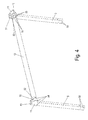
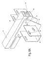
- FIG. 4 a mounting position for a support beam 12 is shown, which is to be mounted between two posts 5.
- each holder 10 are provided, which had a U-shaped receptacle 52 for insertion of an end portion of the supporting beam 12.
- the holders 10 are rotatably mounted together with the outer holders 11 about an axis 51 on the post 5, wherein the axis 51 can be formed by a screw bolt.
- After insertion of the support beam 12 in the downwardly open receptacle 52 of the supporting beam 12 can be fixed to the receptacles 52, for example via fastening bolts 55 which are inserted into the slots 53 on the receptacle 52 and the support beam 12.
- the support beam 12 is now fixed to the holders 10, wherein after mounting all support beams 12, these can now be pivoted upwards from the position shown until the U-shaped receptacle is open at the top, then the support bar 12 in a raised position to fix on the post 5.
- openings 54 are further formed, which can be penetrated by fastening means to mount the longitudinal members 13.
- the posts 5 are provided with four openings 50 into which fastening means in the form of bolts 9 can be inserted for mounting on the pedestals 4.
- the foundations 3 are poured and then the base 4 is fixed thereto.
- the posts 5, 6, 7, 8 loosely fixed to the sockets 4 in a V-shaped orientation
- the fastening means 9 are inserted in the form of bolts in the openings 50 of the posts 5 and the other posts 6, 7, 8 but not yet clamped.
- the posts 5, 6, 7, 8 can be pivoted relative to the base 4 with a certain play.
- the holders 10 and 11 are mounted on the posts 5, 6, 7, 8, which are rotatably mounted about the axis 51.
- the support beams 12 are now mounted, as in connection with FIG. 4 has been described.
- the support beams 12 are pivoted together with the holders 10 about a horizontal axis, to then be fixed in a raised position on the posts 5, 6, 7 and 8.
- the longitudinal members 13 are positioned on the holders 10 and 11, which can be inserted, for example, on the side of the shorter post 5 from below between the holder 10 and 11.
- the end-side holder 10 and 11 to the posts 5, 6, 7 and 8 are usually not exactly on a line, the side rails 13 can be fixed to the holders 10 and 11, since the posts 5, 6, 7, 8 to the Sockets 4 are still arranged movable to a certain extent.
- a self-teaching assembly is possible because the posts 5, 6, 7, 8 are aligned by the side members.
- the posts 5, 6, 7, 8 are fixed to the sockets 4 by clamping.
- the assembly thereby enables the compensation of tolerances with regard to the height of the base 4, the alignment of the posts 5, 6, 7, 8 and other influences.
- the support structure 1 is flexibly adaptable to such deviations.
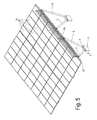
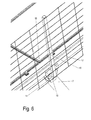
- FIG. 5 a support structure is shown, in which at the top of a solar system with photovoltaic modules 15 is mounted.
- 11 posts 16 are mounted on the outer holders, as well as from the enlarged view of FIG. 6 is recognizable.
- Each post 16 is fixed via a flange 18 to a holder 11 1, wherein the posts 16 hold a net 17, which secures persons located on the roof against falling.
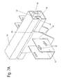
- FIGS. 7A and 7B is a further embodiment of a cross member 13 'for a support structure of FIG. 1 shown.
- the side members 13 via fastening screws 9 rigid with the Owners 10 and 11 connected.
- the side members 13 'according to the FIGS. 7A and 7B provide with lateral grooves 40 to which the holder 10 'are slidably mounted.
- the holders 10 ' have, as in the previous embodiment, a U-shaped receptacle 52, in which horizontal slots 53 are provided for the displaceable mounting of the support beams 12.
- the holders 10 'further include a mounting portion 44 which is bent angularly and engages in the groove 40 of the longitudinal member 13'.
- the groove 40 in this case has an outer slot 41, which is narrower than an inner space 42 of the groove into which the angled portion 44 of the holder 10 'engages.
- the holder 10 ' can be mounted by pivoting or pushing on the side member 13'.
- other components can be attached, for example, in FIG. 5 shown side posts 16 for mounting a fall protection.
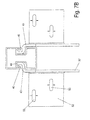
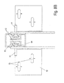
- FIGS. 8A and 8B is a further embodiment of a longitudinal member 13 "shown in the support structure of FIG. 1 can be mounted.
- the side member 13 includes a groove 60 which has a tapered neck portion 64 narrower than an interior of the groove 60.
- screw heads 62 slidably mounted along the groove 60 can be disposed in the groove 60.
- Screw bolts 62 62 are provided, which pass through the openings 54 in the holder 10 "and thus the holder 10" slidably on the longitudinal member 13 "store.
- the holder 10 is again provided with a U-shaped receptacle 52 with horizontal oblong holes 53 for fixing the supporting beams 12.
- the holder 10 can be” relative to the longitudinal carrier 13 ". can be tightened by nuts which are turned on the bolts 61. Further, further bolts 61 can be mounted on the groove 60 to fix other objects.
- the support structure according to the invention can also be adapted to a large extent flexible on the site, the use of the support structure 1 as a shelter, roof, solar system or green roofs is possible. Other purposes, such as carports or garages, are possible.
Landscapes
- Engineering & Computer Science (AREA)
- Architecture (AREA)
- Chemical & Material Sciences (AREA)
- Sustainable Development (AREA)
- Sustainable Energy (AREA)
- Thermal Sciences (AREA)
- Physics & Mathematics (AREA)
- Combustion & Propulsion (AREA)
- Mechanical Engineering (AREA)
- General Engineering & Computer Science (AREA)
- Life Sciences & Earth Sciences (AREA)
- Civil Engineering (AREA)
- Structural Engineering (AREA)
- Roof Covering Using Slabs Or Stiff Sheets (AREA)
- Buildings Adapted To Withstand Abnormal External Influences (AREA)
Abstract
Eine Tragkonstruktion (1), insbesondere für einen Unterstand, umfasst mindestens zwei bodenseitig festlegbare Träger (2), die jeweils zwei V-förmig angeordnete Pfosten (5, 6, 7, 8) umfassen, wobei zwei Prosten (5, 6, 7, 8) zweier beabstandeter Träger (2) über einen quer zur Ebene der Pfosten (5, 6, 7, 8) angeordneten Tragbalken (12) verbunden sind und der Tragbalken (12) an gegenüberliegenden Enden in einem Halter (10) aufgenommen ist, wobei die Halter (10) in einer Montageposition um eine horizontale Achse (51) drehbar an einem Pfosten (5, 6, 7, 8) gelagert sind und nach Ausrichtung des Tragbalkens (12) an dem Pfosten (5, 6, 7, 8) fixierbar sind. Ferner betrifft die Erfindung ein Verfahren zur Montage einer Tragkonstruktion (1).A support structure (1), in particular for a shelter, comprises at least two supports (2) which can be fixed on the bottom side, each comprising two V-shaped posts (5, 6, 7, 8), two prostheses (5, 6, 7, 8) of two spaced supports (2) are connected via a transversely to the plane of the posts (5, 6, 7, 8) arranged support beam (12) and the support beam (12) is received at opposite ends in a holder (10), wherein the holders (10) are rotatably mounted in a mounting position about a horizontal axis (51) on a post (5, 6, 7, 8) and after alignment of the support beam (12) on the post (5, 6, 7, 8) can be fixed. Furthermore, the invention relates to a method for mounting a supporting structure (1).
Description
Die vorliegende Erfindung betrifft eine Tragkonstruktion nach dem Oberbegriff des Anspruches 1 sowie ein Verfahren zur Montage einer Tragkonstruktion.The present invention relates to a support structure according to the preamble of claim 1 and a method for mounting a support structure.
Die
Es ist daher Aufgabe der vorliegenden Erfindung, eine Tragkonstruktion und ein Verfahren zur Montage einer Tragkonstruktion zu schaffen, die einfach zu montieren ist und Toleranzen bei der Montage ausgleichen kann.It is therefore an object of the present invention to provide a support structure and a method for mounting a support structure, which is easy to assemble and can compensate for tolerances in the assembly.
Diese Aufgabe wird mit einer Tragkonstruktion mit den Merkmalen des Anspruches 1 sowie einem Verfahren zur Montage einer Tragkonstruktion mit den Merkmalen des Anspruches 12 gelöst.This object is achieved with a support structure having the features of claim 1 and a method for mounting a support structure with the features of
Bei der erfindungsgemäßen Tragkonstruktion ist ein Tragbalken an gegenüberliegenden Enden an oder in einem Halter aufgenommen und ist in einer Montageposition um eine horizontale Achse drehbar an einem Pfosten gelagert, um dann nach Ausrichtung des Tragbalkens an dem Pfosten fixiert zu werden. Dadurch ist es möglich, den Tragbalken von unten an den Halter zu montieren, der dann um eine horizontale Achse verschwenkt und an den Pfosten festgelegt wird. Dies ermöglicht eine Montage der Tragbalken ohne schwere Hebegeräte, die erst mühsam zur Baustelle transportiert werden müssen. Je nach Länge des Tragbalkens kann dieser sogar manuell an oder in dem Halter festgelegt werden. Zudem ist eine selbstlehrende Ausrichtung der Pfosten und der Halter möglich.In the support structure according to the invention, a support beam is received at opposite ends on or in a holder and is rotatably mounted in a mounting position about a horizontal axis on a post to then be fixed after alignment of the support beam to the post. This makes it possible to mount the support beam from below to the holder, which is then pivoted about a horizontal axis and fixed to the post. This allows mounting of the support beams without heavy lifting equipment, which must be laboriously transported to the site. Depending on the length of the support beam, this can even be set manually on or in the holder. In addition, a self-teaching alignment of the posts and the holder is possible.
Vorzugsweise weisen die Halter eine U-förmige Aufnahme auf, in die ein Endabschnitt eines Tragbalkens einfügbar ist. Dabei kann in einer Montageposition die U-förmige Aufnahme nach unten geöffnet sein, um den Tragbalken einzuschieben, der dann an dem Halter vorfixiert wird. Anschließend kann der Halter zusammen mit den Tragbalken um die horizontale Achse gedreht und fixiert werden.Preferably, the holders have a U-shaped receptacle into which an end portion of a supporting beam can be inserted. In this case, in a mounting position, the U-shaped receptacle can be opened downwards in order to insert the support bar, which is then pre-fixed to the holder. Subsequently, the holder can be rotated together with the support beams about the horizontal axis and fixed.
Gemäß einer bevorzugten Ausgestaltung umfassen die Träger einen Sockel, an dem zwei Pfosten in einer V-Förmigen Ausrichtung festgelegt sind. Dadurch können die statischen Belastungen auf die Pfosten gering gehalten werden, da keine extreme Schrägstellung der Pfosten notwendig ist.According to a preferred embodiment, the carriers comprise a base on which two posts are fixed in a V-shaped orientation. As a result, the static loads on the posts can be kept low because no extreme inclination of the posts is necessary.
Für eine stabile Tragkonstruktion kann an zwei an einem Träger festgelegten Pfosten ein Längsträger vorgesehen sein, der an den Haltern am oberen Ende der Pfosten festgelegt ist. Der Längsträger kann dabei an den Haltern über Schraubverbindungen fixiert sein. Es ist auch möglich, den Längsträger an den Haltern verschiebbar zu lagern, um auch eine Ausrichtung des Längsträgers relativ zu den Haltern vornehmen zu können, was Belastungen durch Spannungen vermeidet.For a stable support structure can be provided on two fixed to a support post, a side rail, which is fixed to the holders at the top of the post. The longitudinal member can be fixed to the holders via screw. It is also possible to displaceably mount the longitudinal member to the holders in order to be able to align the longitudinal member relative to the holders, which avoids strains due to stresses.
Für die Herstellung einer größeren Tragkonstruktion ist es vorteilhaft, wenn in der Ebene der zwei an einem Träger angeordneten Pfosten mindestens ein weiterer Träger mit zwei V-förmig angeordneten Pfosten vorgesehen ist. Vorzugsweise sind die Pfosten eines ersten Trägers mit den Pfosten eines zweiten Trägers über einen Längsträger miteinander verbunden, wobei der Längsträger an den Haltern an den einzelnen Pfosten fixiert werden kann. Dadurch kann ein durchgängiger Längsträger an einer Vielzahl von Pfosten gehalten werden, beispielsweise zwei, vier oder mehr Pfosten. Die Pfosten können dabei eine unterschiedliche Länge aufweisen, so dass der Längsträger geneigt zur Horizontalen ausgerichtet wird, was die Montage eines Schrägdaches ermöglicht.For the production of a larger support structure, it is advantageous if at least one further support with two V-shaped posts is provided in the plane of the two posts arranged on a support. Preferably, the posts of a first carrier are connected to the posts of a second carrier via a longitudinal beam, wherein the longitudinal carrier can be fixed to the holders on the individual posts. As a result, a continuous side member can be held on a plurality of posts, for example two, four or more posts. The posts can have a different length, so that the longitudinal beam is aligned inclined to the horizontal, which allows the installation of a pitched roof.
Die Tragkonstruktion kann insbesondere als Unterstand eingesetzt werden, indem auf die Tragbalken und die Längsträger ein Dach montiert wird. Zusätzlich ist es möglich, die Tragkonstruktion auch für eine Solaranlage zu verwenden, beispielsweise wenn eine Unterkonstruktion an den Tragbalken oder dem Dach fixiert wird.The support structure can be used in particular as a shelter by a roof is mounted on the support beams and the side members. In addition, it is possible to use the support structure for a solar system, for example, when a substructure is fixed to the support beam or the roof.
Bei dem erfindungsgemäßen Verfahren zur Montage der Tragkonstruktion werden zunächst mindestens zwei beabstandete Träger mit Sockeln mit jeweils zwei V-förmig angeordneten Pfosten montiert, wobei jeweils ein drehbar gelagerter Halter an jedem oberen Ende eines Pfostens montiert wird. Anschließend wird ein Tragbalken an zwei Haltern, die an Pfosten der beabstandeten Träger vorgesehen sind, festgelegt. Die Halter werden dann mit dem Tragbalken um eine horizontale Achse gedreht, um dann mit dem Tragbalken an den Pfosten fixiert zu werden. Dies ermöglicht eine einfache Montage und eine einfache Ausrichtung des Tragbalkens auch bei Toleranzen bei der Montage der Sockel.In the method according to the invention for mounting the support structure, at least two spaced-apart supports are first mounted with pedestals each having two V-shaped posts, wherein in each case a rotatably mounted holder is mounted on each upper end of a post. Subsequently, a support beam is fixed to two brackets provided on posts of the spaced beams. The holders are then rotated with the support beam about a horizontal axis, to then be fixed with the support beam to the post. This allows easy installation and easy alignment of the support beam even with tolerances in the mounting of the base.
Vorzugsweise wird an den Haltern an den Pfosten eines Trägers ein Längsträger fixiert, bevor die Halter mit den Tragbalken festgelegt werden. Dies ermöglicht eine selbstlehrende Montage, da der Tragbalken zunächst an den Haltern ausgerichtet wird und dabei ein Ausrichten der Halter an den Pfosten möglich ist, bevor diese dann über Schraub- oder Klemmverbindungen aneinander fixiert werden. Gleichermaßen ist es möglich, dass die Pfosten an dem Sockel mit einem gewissen Spiel gehalten sind, beispielsweise durch lose Schraubverbindungen, damit erst nach der Montage eines Längsträgers ein Anziehen der Verbindungsstellen am Sockel erfolgt, um die Pfosten zu fixieren. Eine solche selbstlehrende Konstruktion vermeidet Spannungen aufgrund von Toleranzen bei der Ausrichtung der Sockel, der Pfosten und/oder der Halter.Preferably, a side rail is fixed to the brackets on the uprights of a carrier before the brackets are secured to the support beams. This allows a self-teaching assembly, since the support beam is first aligned with the holders while aligning the holder on the post is possible before they are then fixed via screw or clamp connections together. Similarly, it is possible that the posts are held on the base with a certain amount of play, for example by loose screw, so that only after mounting a side member tightening the joints on the base is done to fix the posts. Such a self-teaching construction avoids stresses due to tolerances in the alignment of the pedestals, the posts and / or the holders.
Die Erfindung wird nachfolgend anhand mehrerer Ausführungsbeispiele mit Bezug auf die beigefügten Zeichnungen näher erläutert. Es zeigen:
- Figur 1
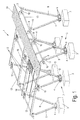
- eine perspektivische Explosionsdarstellung einer erfindungsgemäßen Tragkonstruktion;
Figur 2- eine perspektivische Ansicht eines Ausschnittes der Tragkonstruktion der
Figur 1 ; Figur 3- eine vergrößerte perspektivische Ansicht der Tragkonstruktion der
Figur 2 Figur 4- eine perspektivische Ansicht zweier Pfosten und eines Tragbalkens bei der Montage der erfindungsgemäßen Tragkonstruktion;
Figur 5- eine perspektivische Ansicht einer Tragkonstruktion mit Solaranlage;
Figur 6- eine perspektivische Detailansicht eines Seitenbereiches der Tragkonstruktion der
Figur 5 - Figuren 7A und 7B
- zwei Ansichten eines modifizierten Längsträgers für eine erfindungsgemäße Tragkonstruktion, und
- Figuren 8A und 8B
- zwei Ansichten eines weiteren Ausführungsbeispiels eines modifizierten Längsträgers für eine erfindungsgemäße Tragkonstruktion.
- FIG. 1
- an exploded perspective view of a support structure according to the invention;
- FIG. 2
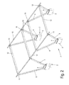
- a perspective view of a section of the support structure of
FIG. 1 ; - FIG. 3
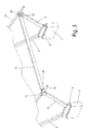
- an enlarged perspective view of the support structure of
FIG. 2 ; - FIG. 4
- a perspective view of two posts and a supporting beam during assembly of the support structure according to the invention;
- FIG. 5
- a perspective view of a support structure with solar system;
- FIG. 6
- a detailed perspective view of a side portion of the support structure of
FIG. 5 ; - FIGS. 7A and 7B
- two views of a modified longitudinal member for a support structure according to the invention, and
- Figures 8A and 8B
- two views of another embodiment of a modified side member for a support structure according to the invention.
Eine Tragkonstruktion 1 umfasst eine Vielzahl bodenseitig festlegbarer Träger 2, die ein bodenseitig festgelegtes Fundament 3, beispielsweise aus Beton, aufweisen, an dem ein Sockel 4 festgelegt ist. Der Sockel 4 ist als U-förmiges Metallprofil ausgebildet, das bodenseitig an dem Fundament 3 festgelegt ist und zwei Seitenwände besitzt, an denen Pfosten 5, 6, 7, 8 festgelegt werden. Dabei sind an jedem Sockel 4 zwei Pfosten 5 und 6 oder 7 und 8 in einer V-förmigen Anordnung fixiert. Die Pfosten 5, 6, 7, 8 weisen eine unterschiedliche Länge auf, damit die Tragkonstruktion zur Montage eines Schrägdaches eingesetzt werden kann. Es ist natürlich möglich, die Pfosten 5, 6, 7, 8 auch in gleicher Länge vorzusehen.A support structure 1 comprises a plurality of base-side
Die Pfosten 5, 6, 7, 8 sind über Befestigungsmittel in Form von Schraubbolzen 9 an dem Sockel 4 festgelegt.The
An den oberen Enden der Pfosten 5, 6, 7, 8 sind Halter 10 vorgesehen, die zur Festlegung von Tragbalken 12 dienen. Die Tragbalken 12 sind dabei im Wesentlichen senkrecht zu der Ebene angeordnet, die durch zwei Pfosten 5, 6, 7, 8 eines Trägers 2 aufgespannt wird. Neben den Haltern 10 sind äußere Halter 11 vorgesehen, die allerdings nicht zur Befestigung der Tragbalken 12 dienen, sondern lediglich zur Fixierung von Längsträgern 13 verwendet werden. Die Längsträger 13 sind jeweils in der von den Pfosten 5, 6, 7, 8 aufgespannten Ebene angeordnet, wobei in dem gezeigten Ausführungsbeispiel ein Längsträger 13 über vier Halter 10 und 11 endseitig an den Pfosten 5, 6, 7, 8 festgelegt ist. Es ist natürlich auch möglich, den Längsträger 13 nur an zwei Pfosten 5 und 6 oder mehr als vier Pfosten 5, 6, 7, 8 zu fixieren.At the upper ends of the
Die Tragbalken 12 und die Längsträger 13 sind in der montierten Position an ihrer Oberseite im Wesentlichen auf einer Ebene angeordnet, um die Montage eines Daches 19 zu erleichtern.The support beams 12 and the
Wie in
In
Für die Montage der Tragkonstruktion werden zunächst die Fundamente 3 gegossen und dann die Sockel 4 darauf fixiert. Anschließend werden die Pfosten 5, 6, 7, 8 an den Sockeln 4 in V-förmiger Ausrichtung lose fixiert, wobei die Befestigungsmittel 9 in Form von Schraubbolzen in die Öffnungen 50 der Pfosten 5 und der anderen Pfosten 6, 7, 8 eingesteckt werden, aber noch nicht festgeklemmt werden. Dadurch können die Pfosten 5, 6, 7, 8 mit einem gewissen Spiel relativ zu dem Sockel 4 verschwenkt werden. Anschließend werden die Halter 10 und 11 an den Pfosten 5, 6, 7, 8 montiert, die um die Achse 51 drehbar gelagert sind. An den Haltern 10 werden nun die Tragbalken 12 montiert, wie dies in Verbindung mit
Anschließend werden an den Haltern 10 und 11 die Längsträger 13 positioniert, die beispielsweise an der Seite der kürzeren Pfosten 5 von unten zwischen die Halter 10 und 11 eingeschoben werden können. Die endseitigen Halter 10 und 11 an den Pfosten 5, 6, 7 und 8 liegen meist nicht exakt auf einer Linie, wobei die Längsträger 13 an den Haltern 10 und 11 fixiert werden können, da die Pfosten 5, 6, 7, 8 an den Sockeln 4 noch in einem gewissen Maß beweglich angeordnet sind. Dadurch ist eine selbstlehrende Montage möglich, da die Pfosten 5, 6, 7, 8 durch die Längsträger ausgerichtet werden. Nach Montage der Längsträger 13 können dann die Pfosten 5, 6, 7, 8 an den Sockeln 4 klemmend festgelegt werden. Die Montage ermöglicht dadurch den Ausgleich von Toleranzen im Hinblick auf die Höhe der Sockel 4, der Ausrichtung der Pfosten 5, 6, 7, 8 und anderer Einflüsse. Die Tragkonstruktion 1 ist flexibel an solche Abweichungen anpassbar.Subsequently, the
In
In den
In den
Die erfindungsgemäße Tragkonstruktion kann auch auf der Baustelle noch weitgehend flexibel angepasst werden, wobei der Einsatz der Tragkonstruktion 1 als Unterstand, Dach, Solaranlage oder zur Dachbegrünung möglich ist. Auch andere Einsatzzwecke, beispielsweise für Carports oder Garagen, sind möglich.
Claims (15)
dadurch gekennzeichnet, dass die Halter (10) in einer Montageposition um eine horizontale Achse (51) drehbar an einem Pfosten (5, 6, 7, 8) gelagert sind und nach Ausrichtung des Tragbalkens (12) an dem Pfosten (5, 6, 7, 8) fixierbar sind.
characterized in that the holders (10) in a mounting position about a horizontal axis (51) are rotatably mounted on a post (5, 6, 7, 8) and after alignment of the support beam (12) on the post (5, 6, 7, 8) are fixable.
Applications Claiming Priority (1)
| Application Number | Priority Date | Filing Date | Title |
|---|---|---|---|
| DE102012104663A DE102012104663A1 (en) | 2012-05-30 | 2012-05-30 | Supporting structure and method for mounting a supporting structure |
Publications (2)
| Publication Number | Publication Date |
|---|---|
| EP2669451A2 true EP2669451A2 (en) | 2013-12-04 |
| EP2669451A3 EP2669451A3 (en) | 2015-11-25 |
Family
ID=48444211
Family Applications (1)
| Application Number | Title | Priority Date | Filing Date |
|---|---|---|---|
| EP13168233.8A Withdrawn EP2669451A3 (en) | 2012-05-30 | 2013-05-17 | Support structure and method for assembling a support structure |
Country Status (2)
| Country | Link |
|---|---|
| EP (1) | EP2669451A3 (en) |
| DE (1) | DE102012104663A1 (en) |
Cited By (11)
| Publication number | Priority date | Publication date | Assignee | Title |
|---|---|---|---|---|
| CN104329818A (en) * | 2014-11-05 | 2015-02-04 | 嘉兴四海通达新能源科技有限公司 | Solar water heater holder |
| CN106301165A (en) * | 2016-08-25 | 2017-01-04 | 广东南能新能源有限公司 | photovoltaic module mounting bracket |
| GB2567707A (en) * | 2017-10-23 | 2019-04-24 | Inside2Outside Ltd | Roof support structure |
| US10505492B2 (en) | 2016-02-12 | 2019-12-10 | Solarcity Corporation | Building integrated photovoltaic roofing assemblies and associated systems and methods |
| CN111779032A (en) * | 2020-07-08 | 2020-10-16 | 国网江苏省电力有限公司连云港供电分公司 | A prefabricated combined octagonal cable well and its construction method |
| CN115680181A (en) * | 2023-01-04 | 2023-02-03 | 北京市建筑工程研究院有限责任公司 | Material-saving and wind-resistant cable-membrane structure building and construction method thereof |
| WO2024160775A1 (en) * | 2023-02-02 | 2024-08-08 | Advanced Coatings & Construction Solutions | Systems for supporting a roof, e.g. for a carport or a canopy, wherein in particular the roof comprises at least one pv panel |
| AT18352U1 (en) * | 2023-05-23 | 2024-10-15 | Swietelsky Ag | Device for supporting a pair of beams combined with a roof to form a triangular structure |
| WO2024229483A1 (en) * | 2023-05-09 | 2024-11-14 | Anywhere.Solar GmbH | Vehicle shelter |
| PL448043A1 (en) * | 2024-03-19 | 2025-09-22 | Przedsiębiorstwo Robót Drogowych Lubartów Spółka Akcyjna | Bracket for the canopy structure |
| WO2025262131A1 (en) * | 2024-06-18 | 2025-12-26 | Free-e GmbH & Co. KG | Roof construction, first roof construction pair, construction extension and construction system |
Families Citing this family (5)
| Publication number | Priority date | Publication date | Assignee | Title |
|---|---|---|---|---|
| CH711867B1 (en) * | 2015-12-10 | 2021-01-15 | Klaus ming | Heat-insulating air dome. |
| US11005415B2 (en) * | 2018-08-23 | 2021-05-11 | Jesse Wolf Corsi Henson | Solar shade structure |
| US11088654B2 (en) * | 2019-10-15 | 2021-08-10 | Solar Foundations Usa, Inc. | Dual pile cap |
| DE102023105249A1 (en) * | 2023-03-03 | 2024-09-05 | Tubesolar Ag | Device and method for the outdoor installation of individual solar modules and solar modules on a substrate |
| FR3148449A1 (en) * | 2023-05-03 | 2024-11-08 | Azenco Groupe | Method of assembling a shelter, in particular a car shelter |
Citations (1)
| Publication number | Priority date | Publication date | Assignee | Title |
|---|---|---|---|---|
| DE202009006182U1 (en) | 2009-05-01 | 2009-10-29 | Schletter Gmbh | shelter |
Family Cites Families (9)
| Publication number | Priority date | Publication date | Assignee | Title |
|---|---|---|---|---|
| GB1420333A (en) * | 1972-03-09 | 1976-01-07 | Rayner L H | Roof supporting structures |
| IT1247183B (en) * | 1991-02-22 | 1994-12-12 | Renato Fontana | MODULAR AND MODULAR RETICULAR STRUCTURE |
| DE202006014047U1 (en) * | 2006-09-13 | 2006-12-07 | Leichtmetallbau Schletter Gmbh | Adjustment system for elevated solar systems |
| ES2369737T3 (en) * | 2009-01-27 | 2011-12-05 | Mounting Systems Gmbh | SET OF ASSEMBLY COMPONENTS TO ERIR SOLAR MODULES. |
| NL2002778C2 (en) * | 2009-04-23 | 2010-10-28 | Valk Systemen Bvvd | TILTABLE CARRYING DEVICE FOR SOLAR PANELS. |
| FR2949243A1 (en) * | 2009-08-18 | 2011-02-25 | Onet Technologies En | Photovoltaic parking shed for use in e.g. farm building, to protect cars from sunshine, has compass shaped side structures including inclined columns whose lower ends are attached to concrete base that forms parking spaces with another base |
| TWI414736B (en) * | 2010-02-02 | 2013-11-11 | Herng Jiunn Liao | One-axis solar tracker system and apparatus with wind lock devices |
| FR2961546B1 (en) * | 2010-06-18 | 2013-11-08 | Ingesun | SHADOW COMPRISED OF POSTS SUBJECT TO A STRUCTURE EQUIPPED WITH PROTECTIVE ELEMENTS AGAINST EXTERNAL ATMOSPHERIC AGENTS |
| DE202011107358U1 (en) * | 2011-10-29 | 2011-11-21 | Reinhard Stiebert | Self-supporting module carrier for solar and PV systems |
-
2012
- 2012-05-30 DE DE102012104663A patent/DE102012104663A1/en not_active Withdrawn
-
2013
- 2013-05-17 EP EP13168233.8A patent/EP2669451A3/en not_active Withdrawn
Patent Citations (1)
| Publication number | Priority date | Publication date | Assignee | Title |
|---|---|---|---|---|
| DE202009006182U1 (en) | 2009-05-01 | 2009-10-29 | Schletter Gmbh | shelter |
Cited By (15)
| Publication number | Priority date | Publication date | Assignee | Title |
|---|---|---|---|---|
| CN104329818A (en) * | 2014-11-05 | 2015-02-04 | 嘉兴四海通达新能源科技有限公司 | Solar water heater holder |
| CN104329818B (en) * | 2014-11-05 | 2016-01-06 | 嘉兴四海通达新能源科技有限公司 | A kind of solar water heater rack |
| US10505492B2 (en) | 2016-02-12 | 2019-12-10 | Solarcity Corporation | Building integrated photovoltaic roofing assemblies and associated systems and methods |
| CN106301165B (en) * | 2016-08-25 | 2019-03-08 | 广东南能新能源有限公司 | Photovoltaic module mounting bracket |
| CN106301165A (en) * | 2016-08-25 | 2017-01-04 | 广东南能新能源有限公司 | photovoltaic module mounting bracket |
| GB2567707A (en) * | 2017-10-23 | 2019-04-24 | Inside2Outside Ltd | Roof support structure |
| WO2019081896A1 (en) * | 2017-10-23 | 2019-05-02 | Inside2Outside Limited | Roof support structure |
| CN111779032A (en) * | 2020-07-08 | 2020-10-16 | 国网江苏省电力有限公司连云港供电分公司 | A prefabricated combined octagonal cable well and its construction method |
| CN115680181A (en) * | 2023-01-04 | 2023-02-03 | 北京市建筑工程研究院有限责任公司 | Material-saving and wind-resistant cable-membrane structure building and construction method thereof |
| WO2024160775A1 (en) * | 2023-02-02 | 2024-08-08 | Advanced Coatings & Construction Solutions | Systems for supporting a roof, e.g. for a carport or a canopy, wherein in particular the roof comprises at least one pv panel |
| WO2024229483A1 (en) * | 2023-05-09 | 2024-11-14 | Anywhere.Solar GmbH | Vehicle shelter |
| AT18352U1 (en) * | 2023-05-23 | 2024-10-15 | Swietelsky Ag | Device for supporting a pair of beams combined with a roof to form a triangular structure |
| PL448043A1 (en) * | 2024-03-19 | 2025-09-22 | Przedsiębiorstwo Robót Drogowych Lubartów Spółka Akcyjna | Bracket for the canopy structure |
| PL249269B1 (en) * | 2024-03-19 | 2026-03-16 | Przedsiębiorstwo Robót Drogowych Lubartów Spółka Akcyjna | Bracket for the canopy structure |
| WO2025262131A1 (en) * | 2024-06-18 | 2025-12-26 | Free-e GmbH & Co. KG | Roof construction, first roof construction pair, construction extension and construction system |
Also Published As
| Publication number | Publication date |
|---|---|
| EP2669451A3 (en) | 2015-11-25 |
| DE102012104663A1 (en) | 2013-12-05 |
Similar Documents
| Publication | Publication Date | Title |
|---|---|---|
| EP2669451A2 (en) | Support structure and method for assembling a support structure | |
| DE102018221183B3 (en) | Adjustment fitting and support system for solar modules | |
| DE102009019548A1 (en) | Assembling module for assembling solar collector at e.g. flat roof of house, has fastening devices displaced at holding rail and fixed in desired position, where holding rails are attached at upper side of columns | |
| EP3599323B1 (en) | Bearing head comprising a clamping device and corresponding ceiling formwork system | |
| EP1647782A2 (en) | Supporting device for at least one solar collector | |
| EP3978825B1 (en) | Device for supporting solar modules, kit, manufacturing method and solar module assembly | |
| EP3715561B1 (en) | Roofing system and support module for same | |
| EP2006613A2 (en) | Fixing device for framework components attachable to a framework, in particular solar modules | |
| DE202009015122U1 (en) | Device for supporting solar modules | |
| EP2378221A2 (en) | Mounting system for solar modules and method for mounting a solar assembly | |
| DE102005032859B3 (en) | Fixing system for solar modules has bent U-shaped holder with arm fixed to mounting rail and sprung bowed piece that can be bolted to press module against the rail | |
| EP2829745B1 (en) | Corner connector for a substructure frame, in particular for holding laying nests | |
| DE10307866B4 (en) | Glass facade of frameless laid glass panels | |
| EP2378563A2 (en) | Mounting system for solar modules | |
| EP2213961A2 (en) | Device for elevating solar modules | |
| EP2602862A1 (en) | Antenna holder | |
| AT523944B1 (en) | railing module | |
| DE102006053831B4 (en) | Fastening device for to be arranged on a frame structure frame members, in particular solar modules | |
| EP3216942A1 (en) | Floor construction system | |
| WO2016156382A1 (en) | Mounting system and mounting method | |
| DE9312108U1 (en) | Metal skeleton for the final expansion into a walk-in multi-purpose container | |
| WO2012055403A2 (en) | Module block for holding a photovoltaic module | |
| DE102018203080B4 (en) | FOUNDATION SYSTEM FOR THE STORAGE OF SOLAR PANELS ARRANGED ALONGSIDE | |
| CH711544B1 (en) | Solar module-carrying device. | |
| EP3970270B1 (en) | Longitudinal profile and module clamp for a mounting system for solar modules, and a mounting system of such a type |
Legal Events
| Date | Code | Title | Description |
|---|---|---|---|
| PUAI | Public reference made under article 153(3) epc to a published international application that has entered the european phase |
Free format text: ORIGINAL CODE: 0009012 |
|
| AK | Designated contracting states |
Kind code of ref document: A2 Designated state(s): AL AT BE BG CH CY CZ DE DK EE ES FI FR GB GR HR HU IE IS IT LI LT LU LV MC MK MT NL NO PL PT RO RS SE SI SK SM TR |
|
| AX | Request for extension of the european patent |
Extension state: BA ME |
|
| RAP1 | Party data changed (applicant data changed or rights of an application transferred) |
Owner name: VIESSMANN PHOTOVOLTAIK GMBH |
|
| PUAL | Search report despatched |
Free format text: ORIGINAL CODE: 0009013 |
|
| AK | Designated contracting states |
Kind code of ref document: A3 Designated state(s): AL AT BE BG CH CY CZ DE DK EE ES FI FR GB GR HR HU IE IS IT LI LT LU LV MC MK MT NL NO PL PT RO RS SE SI SK SM TR |
|
| AX | Request for extension of the european patent |
Extension state: BA ME |
|
| RIC1 | Information provided on ipc code assigned before grant |
Ipc: H01L 31/042 20140101ALI20151016BHEP Ipc: E04H 6/02 20060101AFI20151016BHEP Ipc: F24J 2/52 20060101ALI20151016BHEP Ipc: F24J 2/04 20060101ALI20151016BHEP |
|
| STAA | Information on the status of an ep patent application or granted ep patent |
Free format text: STATUS: THE APPLICATION IS DEEMED TO BE WITHDRAWN |
|
| 18D | Application deemed to be withdrawn |
Effective date: 20160526 |