EP4108848B1 - Terrace floor substructure with supports for floor coverings - Google Patents
Terrace floor substructure with supports for floor coverings Download PDFInfo
- Publication number
- EP4108848B1 EP4108848B1 EP21181392.8A EP21181392A EP4108848B1 EP 4108848 B1 EP4108848 B1 EP 4108848B1 EP 21181392 A EP21181392 A EP 21181392A EP 4108848 B1 EP4108848 B1 EP 4108848B1
- Authority
- EP
- European Patent Office
- Prior art keywords
- substructure
- terrace floor
- facing
- edge
- floor substructure
- Prior art date
- Legal status (The legal status is an assumption and is not a legal conclusion. Google has not performed a legal analysis and makes no representation as to the accuracy of the status listed.)
- Active
Links
- 125000006850 spacer group Chemical group 0.000 claims description 13
- 238000010079 rubber tapping Methods 0.000 claims description 9
- 230000000284 resting effect Effects 0.000 claims description 2
- 241000272165 Charadriidae Species 0.000 claims 2
- NJPPVKZQTLUDBO-UHFFFAOYSA-N novaluron Chemical compound C1=C(Cl)C(OC(F)(F)C(OC(F)(F)F)F)=CC=C1NC(=O)NC(=O)C1=C(F)C=CC=C1F NJPPVKZQTLUDBO-UHFFFAOYSA-N 0.000 description 9
- 230000007797 corrosion Effects 0.000 description 2
- 238000005260 corrosion Methods 0.000 description 2
- 238000007789 sealing Methods 0.000 description 2
- 230000001419 dependent effect Effects 0.000 description 1
- 230000001066 destructive effect Effects 0.000 description 1
- 210000003195 fascia Anatomy 0.000 description 1
- 238000003780 insertion Methods 0.000 description 1
- 230000037431 insertion Effects 0.000 description 1
- 238000004519 manufacturing process Methods 0.000 description 1
Images


Classifications
-
- E—FIXED CONSTRUCTIONS
- E04—BUILDING
- E04F—FINISHING WORK ON BUILDINGS, e.g. STAIRS, FLOORS
- E04F15/00—Flooring
- E04F15/02—Flooring or floor layers composed of a number of similar elements
- E04F15/024—Sectional false floors, e.g. computer floors
- E04F15/02447—Supporting structures
- E04F15/02458—Framework supporting the panels
-
- E—FIXED CONSTRUCTIONS
- E04—BUILDING
- E04F—FINISHING WORK ON BUILDINGS, e.g. STAIRS, FLOORS
- E04F15/00—Flooring
- E04F15/02—Flooring or floor layers composed of a number of similar elements
- E04F15/02177—Floor elements for use at a specific location
- E04F15/02183—Floor elements for use at a specific location for outdoor use, e.g. in decks, patios, terraces, verandas or the like
-
- E—FIXED CONSTRUCTIONS
- E04—BUILDING
- E04F—FINISHING WORK ON BUILDINGS, e.g. STAIRS, FLOORS
- E04F15/00—Flooring
- E04F15/02—Flooring or floor layers composed of a number of similar elements
- E04F15/024—Sectional false floors, e.g. computer floors
- E04F15/02447—Supporting structures
- E04F15/02464—Height adjustable elements for supporting the panels or a panel-supporting framework
-
- E—FIXED CONSTRUCTIONS
- E04—BUILDING
- E04F—FINISHING WORK ON BUILDINGS, e.g. STAIRS, FLOORS
- E04F15/00—Flooring
- E04F15/02—Flooring or floor layers composed of a number of similar elements
- E04F15/02044—Separate elements for fastening to an underlayer
- E04F2015/0205—Separate elements for fastening to an underlayer with load-supporting elongated furring elements between the flooring elements and the underlayer
- E04F2015/02066—Separate elements for fastening to an underlayer with load-supporting elongated furring elements between the flooring elements and the underlayer with additional fastening elements between furring elements and flooring elements
- E04F2015/02077—Separate elements for fastening to an underlayer with load-supporting elongated furring elements between the flooring elements and the underlayer with additional fastening elements between furring elements and flooring elements the additional fastening elements located in-between two adjacent flooring elements
Definitions
- the invention is based on a terrace floor substructure with the features of the preamble of claim 1.
- a terrace floor substructure is from CN 112 942 731 A known.
- Another patio floor substructure is from the DE 20 2015 105013 U1 known.
- Another terrace floor substructure is from the DE 20 2015 005 659 U1 known.
- a similar terrace floor substructure is also described in DE 10 2019 132 571 A1 .
- the terrace floor substructures known from the prior art have the disadvantage that the attachment of a transverse connector to the profile strut, which is required for the arrangement of a transverse profile which extends perpendicularly to the profile strut, is associated with a great deal of effort.
- several self-tapping screws must be screwed into the profile strut at a previously precisely measured position in the longitudinal direction of the profile strut. Subsequent readjustment of the position of the cross-connector is only possible to a limited extent without exposing the previously unsuccessful holes for fastening the cross-connector and thus creating points of attack for weather and corrosion.
- the slot nut faces the undercut retaining groove Page is rigidly connected and rotatably received in the retaining groove between a release position and a locking position.
- the cross connector is locked in an undercut groove on one of the opposite vertical sides of the profile strut.
- the locking can be done without tools due to the undercut of the groove.
- the cross-connector can be fastened in the undercut groove with a friction fit.
- the cross-connector can have a sliding block on its side facing the undercut groove, with which the cross-connector is locked in the undercut groove, for example during a 90° rotation after the sliding block has been previously inserted into the undercut groove.
- the release position and the locking position can be displaced relative to one another by a 90° rotation about an axis which extends perpendicularly to the vertical side having the undercut groove.
- the sliding block can engage behind the retaining groove in the locking position and be arranged completely in line with a clear opening of the undercut retaining groove in the release position.
- the sliding block In the locking position, the sliding block can rest with opposite, short end faces in a frictional connection on opposite inner sides of an undercut of the undercut retaining groove.
- the short end faces can have a radius or a run-on contour.
- the transverse connector can be designed as a retaining shoe open to the upper side of the lower support frame.
- the support shoe may have a horizontal bottom side and two side walls extending parallel to one another and perpendicular to the bottom side at opposite edges of the bottom side.
- the base side and the two side walls extending perpendicularly to the base side can be connected on their sides facing the undercut groove to the side of the cross connector or edge holder facing the undercut retaining groove, in particular extending perpendicular to the side facing the undercut retaining groove.
- At least one of the side walls can have an opening for a fastener, preferably for a self-tapping screw, with the opening preferably being in the form of an elongated hole with a horizontal direction of extension.
- the opening can be used to connect an end of a further profile strut extending perpendicularly to the profile strut to the holding shoe, for example by screwing a self-tapping screw through the slot-shaped opening into the further profile strut.
- screwing the additional profile strut to the retaining shoe, which is open at the top is optional.
- the additional profiled strut is simply inserted into the holding shoe and fixed or clamped there in a frictional connection.
- the at least one edge holder can be arranged on the outer circumference of the sub-support frame. At least one spacer can rest with a contact side on the edge holder and have a wall connection with a support surface at an end of the contact side facing away from the edge holder.
- the patio floor substructure according to the invention is therefore also suitable for being fastened without tools to any longitudinal position of the profile strut in the manner already described with reference to the cross connector, in order to position a wall connection to a building wall, for example.
- the terrace floor substructure can have a base holder, which rests with a bearing side on the edge holder and has a fastening means for a panel of a vertical facing of the terrace floor substructure at an end of the bearing side facing away from the edge holder.
- the spacer and the socket holder can be of identical design.
- the fastening means for the panels of a vertical facing of the patio floor substructure can be set up to engage over the panels of a vertical facing at their upper longitudinal edge.
- the fastening means can have a U-shaped receptacle for the panels on its underside facing the upper longitudinal edge of the panels.
- the fastening means can encompass the longitudinal edge of the panel with the U-shaped receptacle, so that the panel is held in the U-shaped receptacle.
- the base holder can have a cover strip, which extends in the vertical direction and is designed to cover on the one hand an upper longitudinal edge of a panel of a vertical cover of the terrace floor substructure and on the other hand a free edge of a floor covering lying on the supporting frame.
- the subframe can be supported at least on its outer circumference on at least one pedestal.
- a further fastening means can be fastened to the pedestal, which extends from the pedestal in the direction of the panels and has a further U-shaped receptacle for the panels on its upper side facing the lower longitudinal edge of the panels opposite the upper longitudinal edge.
- the U-shaped receptacle and the further U-shaped receptacle can be arranged with their openings aligned with one another facing one another.
- the support side can have a slot-shaped opening extending in the direction of connection between the wall connection and the undercut retaining groove.
- a profile system is described with which a terrace floor substructure of the type described above can be formed.
- the profile system can have a plurality of profile struts forming a supporting frame for floor coverings, each of which has a longitudinal groove open to its upper side, in which an element for fastening and/or aligning floor coverings is inserted in a longitudinally displaceable manner.
- the element is particularly preferably also adjustable in a direction that extends perpendicular to the longitudinal direction of the longitudinal groove and perpendicular to the depth of the longitudinal groove.
- the element for fastening and/or aligning the floor coverings can have an upper part with a spacer or a clamping element for engagement in a lateral groove of a floor covering and a lower part which is guided in the longitudinal groove in the longitudinal direction.
- the cross spacer and the clamping element can in principle for example in the from the DE 10 2016 000 829 A1 be formed known manner.
- the upper part and the lower part can be guided in the direction that extends perpendicular to the longitudinal direction of the longitudinal groove and perpendicular to the depth of the longitudinal groove so that they can be displaced relative to one another via a sliding guide in order to enable the element for fastening and/or aligning floor coverings to be displaced according to the invention in the two spatial directions extending perpendicular to one another, in particular in two horizontal spatial directions.
- One of the upper part and the lower part can have at least one elongated hole that extends in a direction that extends perpendicular to the longitudinal direction of the longitudinal groove and perpendicular to the depth of the longitudinal groove.
- the other of the upper part and the lower part can have at least one pin guided in the at least one elongated hole.
- the lower part can have three parallel elongated holes, which are preferably designed as through holes.
- the slots can preferably extend in the direction perpendicular to the longitudinal direction of the longitudinal groove and perpendicular to the depth of the longitudinal groove.
- the elongated holes can be part of the sliding guide, with the help of which the lower part and the upper part are guided to be displaceable relative to one another.
- the upper part can have a pin extending from its side facing the lower part, which is guided in a central one of the three parallel longitudinal holes.
- the upper part can have at least two openings which, in a target orientation of the upper part in relation to the lower part in the direction of rotation around the axis of symmetry of a pin of the upper part, with which the upper part is guided in a central one of the three elongated holes of the lower part, are aligned with the other two, outer elongated holes of the three elongated holes.
- one fastening means preferably a screw, can extend through the openings in the upper part into the respectively aligned elongated hole and thus fix the upper part to the lower part in a rotationally fixed manner in the direction of rotation.
- At least one of the fastening means can extend through the upper part and the lower part into a bottom profile side of the longitudinal groove.
- the fastening means can be a self-tapping screw, for example.
- the upper part may have a clamping element for engaging a lateral groove of a floor covering, from which at least one spigot extends into an elongated hole in the lower part, such as two parallel spigots which extend into the two outer ones of the three parallel elongated holes in the lower part.
- the at least one pin can extend through the at least one elongated hole and be supported on the bottom profile side of the longitudinal groove.
- a spacing of the clamping element from the bottom profile side can be adjusted by the length of the pin.
- the pin can have a length that is dimensioned such that the clamping element is at a distance from the lower part, which corresponds to a vertical distance of a lateral groove of a floor covering from a support side with which the floor covering rests on the terrace floor substructure.
- the clamping element can have a through hole which is aligned with the middle of the three elongated holes in the lower part, so that the upper part can be fastened to the lower part and optionally to a bottom profile side of the longitudinal groove using a fastener, preferably a screw, which extends through the upper part and the middle elongated hole and optionally into the bottom profile side.
- the fastening means can particularly preferably be a self-tapping screw.
- the lower part can have a sliding base which is positively received in the longitudinal groove in the direction which extends perpendicular to the longitudinal direction of the longitudinal groove and perpendicular to the depth of the longitudinal groove.
- the longitudinal groove can preferably have a U-shaped cross section and thus be designed without an undercut.
- the longitudinal groove can be a bottom profile side of the profile strut, which delimits the longitudinal groove on the bottom side. Two parallel, spaced, opposite side walls of the longitudinal groove can extend from the bottom side of the profile in a direction perpendicular to the bottom side of the profile.
- the figure 1 shows an exemplary embodiment of a profile strut 3 in the cross-sectional view.
- This is designed as a hollow profile with a substantially rectangular cross section.
- the profile strut 3 can be designed, for example, as an extruded profile and accordingly have a constant cross section over its entire length.
- figure 2 shows, on the other hand, a profile strut that basically has the same functionality as in figure 1 has shown profile strut 3, but is designed to be more compact in terms of their height in the direction of insertion into the groove 5.
- the profile strut 3 has a receptacle 21 for a cross connector (not shown) on its two opposite vertical sides 20 .
- the receptacle 21 is designed as an undercut retaining groove 24 .
- the undercut retaining groove 24 has a Undercut 29 on opposite vertical sides.
- a slot nut can engage behind the undercut 29 in order to lock a transverse connector and/or an edge holder.
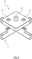
- a suitable cross-connector 22 is in figure 3 shown.
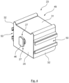
- a suitable edge holder 23 is in figure 4 shown.
- the components 22 , 23 have the sliding block 46 on their side 25 facing the undercut groove 5 .
- the sliding block 46 extends from the side 25 and is arranged at end faces 27 spaced from the side 25 to allow the sliding block 46 to engage the undercut 29 .
- the end faces 27 can be embodied as spherical or circularly contoured friction surfaces, via which the sliding block 46 rests in frictional engagement on the inner sides 28 of the undercut 29 in order to lock the respective component 22, 23 in a locking position in which the sliding block 46 is screwed into the undercut groove 5 in a vertical orientation.
- the locking position and the release position of the sliding block or the respective component 22, 23 are positions rotated by 90° to one another.
- the retaining shoe 30 of the connector 22 can be aligned with its clear opening upwards when the cross connector 22 is in the locking position, in which the two end faces 27 of the sliding block 46 are arranged vertically one above the other and accordingly bear against the inner sides 28 of the undercut 29 with a friction fit.
- the sliding block 46 lies completely in the clear opening 26 of the undercut groove 5, so that the component 22, 23 with its sliding block 46 can be removed from the undercut groove 5.
- the profile strut 3 also has a longitudinal groove 5 on its upper side for receiving an element 4 for fastening and/or aligning floor coverings.
- exemplary embodiments for an upper part 6 and a lower part 10 of such an element 4 are shown in FIGS figures 5 and 6 shown.
- the groove 5 has a bottom profile side 15 and parallel opposite side walls 17, the dimensions of the groove 5 being dimensioned such that, for example, in a form-fitting manner, the lower part 10 according to FIG figure 5 can record, so this only in the vertical to the plane of the drawing figure 1 aligned direction within the longitudinal groove 5 is displaceable.
- the side walls 17 each have a further undercut groove 47 for receiving a sealing element 45 (cf. figure 8 ).
- the transverse connector 22 and the edge holder 23 each have a bottom side 31 and side walls 32 which are spaced apart in parallel.
- the two components 22, 23 also differ in particular in terms of their mounting position in relation to a profile strut 3, as is shown, for example, in figure 8 is shown.
- the cross connector 22 with its retaining shoe 30 is set up to accommodate a profiled strut 3 or one end of a profiled strut 3
- the edge holder 23 serves, for example, to accommodate a spacer 34 (cf. figure 8 ) or a base holder 38 (cf. figure 9 ).
- the transverse connector 22 On each of its opposite side walls 32, the transverse connector 22 has an opening 33 in the form of an elongated hole, which serves as a passage for a fastener, for example a self-tapping screw 14 (cf. figure 8 ) is designed to hold the locking of one end of a profile strut 3 perpendicular to a further profile strut 3, in which the cross connector 22 is suspended via the undercut groove 5.
- the edge holder 23 has a depression 49 on its upper side, in which a support side 35, for example of a spacer 34 or a base holder 38, can be accommodated.
- the edge holder 23 has on each of its parallel, opposite side walls 32 an undercut groove open to the outside or a top-hat rail 50 placed thereon.
- the undercut groove or the fitted top-hat rail 50 can be used to fix a cross-connector, for example the cross-connector 22 according to FIG figure 3 .
- the undercut groove or the attached top hat rail 50 can be aligned with the undercut retaining groove 24 of a profile strut, so that the same mounting height of the undercut groove or the attached top hat rail 50 and the retaining groove 24 is provided.
- figure 5 12 illustrates an exemplary embodiment of a base 10 of an element 4 for fastening and/or aligning floor coverings.
- the lower part 10 has three parallel elongated holes 12 and is otherwise designed in such a way that it is essentially form-fitting in a groove 5 (cf. figures 1 and 2 ) a profile strut 3 to be included.
- the lower part 10 has a sliding surface 19 on opposite longitudinal sides 18, via which the Lower part 10 on the side walls 17 of the groove 5 slidably comes to rest. Both the side walls 17 and the sliding surfaces 19 are preferably designed without contours in order to achieve the best possible sliding behavior of the lower part 10 in the groove 5 .
- the figure 6 shows an upper part 6, which has a spacer 7.
- the upper part 6 can also be set up to have a clamping element 8 which is set up to engage in the lateral groove of a floor covering in order to fix the floor covering to the profile system 2 (cf. figure 7 ).
- the upper part 6 has on its side facing the lower part 10 a pin 13 with which the upper part 6 can engage in the middle of the three grooves 12 of the lower part 10 .
- the pin 13 and thus the upper part 6 can be displaced along the middle groove 12 .
- the width of the middle groove 12 can correspond to the diameter of the pin 13 .
- the adjustability of the pin 13 along the central groove 12 means that the upper part 6 can be adjusted in the direction perpendicular to the longitudinal direction of the groove 5 and thus the position of the spacer cross 7 on the upper side of the upper part 6 is adjustable both in the longitudinal direction of the groove and perpendicular to it, for example to be able to react to manufacturing tolerances of large floor covering formats.
- the upper part 6 has a through hole 9 on opposite sides of the pin 13, which is aligned with the two outer elongated holes 12 of the lower part 10 in a clear orientation in the direction of rotation about the longitudinal axis of the pin 13 in relation to the lower part 10, so that an exact positioning of the upper part 6 in relation to the lower part 10 in the direction of rotation is specified.
- fastening means for example self-tapping screws, can be screwed through the upper part 6, the lower part 10 and into the bottom profile side 15 of the profile strut 3 in order to lock the upper part to the lower part and to fasten the element 4 consisting of the upper part 6 and lower part 10 to the profile 3.
- FIG 8 can also be seen that at the top of the profile strut 3 another undercut groove 47 on the opposite longitudinal sides of the Profile strut 3 is designed to accommodate a plug-in seal 45.
- a spacer 34 is inserted into the depression 49 of the edge holder 23 and is supported with a wall connection 36 via its support surface 37 on a building wall, for example.
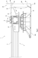
- the figure 9 finally shows a patio floor substructure 1, in which a profile system 2 of the type described above is supported on a pedestal 200.
- the sub-support frame formed from the profile struts 3 has a pedestal bearing 200 at least on its outer circumference, on which the sub-support frame is supported.
- a further fastening means 42 is fastened to the pedestal bearing 200 and extends from the pedestal bearing 200 in the direction of a panel 100 .
- the terrace floor substructure 1 also has a base holder 38 which rests on the edge holder 23 with its support side 35 . At the end of the support side facing away from the edge holder 23 , the base holder has a fastening means 39 for a panel 100 of a vertical facing of the terrace floor substructure 1 .
- the fastening means 39 is set up to engage over the panels 100 at their upper longitudinal edge 101 .
- the fastening means has a U-shaped receptacle 40 for the panels 100 on its underside facing the upper longitudinal edge 101 of the panels 100 .
- the base holder 38 also has, at the end of the support side 35 facing away from the edge holder 23, a cover strip 41 which extends in the vertical direction.
- the cover strip covers on the one hand an upper longitudinal edge 101 of the panels 100 and on the other hand a free edge of a floor covering (not shown) resting on the supporting frame.
- the further fastening means 42 extends from the pedestal bearing 200 in the direction of the panels 100 and has a further receptacle 43 for the panels 100 on its upper side facing the lower longitudinal edge 102 of the panels 100 .
- the U-shaped receptacle 40 and the further receptacle 43 are aligned with one another and are thus prepared to cover the panels 100 in a vertical orientation in an upper edge of the terrace floor substructure 100 and an underside of the pedestal bearing 200 .
Description
Die Erfindung geht aus von einer Terrassenbodenunterkonstruktion mit den Merkmalen des Oberbegriffs des Anspruchs 1. Eine derartige Terrassenbodenunterkonstruktion ist aus der
Die aus dem Stand der Technik bekannten Terrassenbodenunterkonstruktionen haben den Nachteil, dass die für die Anordnung eines Querprofils, welches sich senkrecht zu der Profilstrebe erstreckt, erforderliche Befestigung eines Querverbinders an der Profilstrebe mit hohem Aufwand verbunden ist. Insbesondere müssen dazu mehrere selbstschneidende Schrauben an einer zuvor genau ausgemessenen Position in Längsrichtung der Profilstrebe in die Profilstrebe hineingeschraubt werden. Dabei ist das nachträgliche Nachjustieren der Position des Querverbinders nur bedingt möglich, ohne dabei die zuvor vergeblich eingebrachten Bohrungen für die Befestigung des Querverbinders nicht freizulegen und damit Angriffsstellen für Witterung und Korrosion zu erzeugen.The terrace floor substructures known from the prior art have the disadvantage that the attachment of a transverse connector to the profile strut, which is required for the arrangement of a transverse profile which extends perpendicularly to the profile strut, is associated with a great deal of effort. In particular, several self-tapping screws must be screwed into the profile strut at a previously precisely measured position in the longitudinal direction of the profile strut. Subsequent readjustment of the position of the cross-connector is only possible to a limited extent without exposing the previously unsuccessful holes for fastening the cross-connector and thus creating points of attack for weather and corrosion.
Es ist daher die Aufgabe der Erfindung, eine Terrassenbodenunterkonstruktion der eingangs beschriebenen Art derart weiterzuentwickeln, dass sie die möglichst werkzeuglose Montage des Querverbinders in einer beliebigen Position in Längsrichtung der Profilstrebe erlaubt und im übrigen auch zerstörungsfrei in Bezug auf die Profilstrebe ist, sodass Korrosion der Terrassenbodenunterkonstruktion vorgebeugt wird.It is therefore the object of the invention to further develop a terrace floor substructure of the type described above in such a way that it allows the cross connector to be installed in any position in the longitudinal direction of the profile strut with as few tools as possible and is also non-destructive in relation to the profile strut, so that corrosion of the terrace floor substructure is prevented.
Diese Aufgabe wird durch eine Terrassenbodenunterkonstruktion mit den Merkmalen des Anspruchs 1 gelöst. Vorteilhafte Ausführungsformen sind jeweils Gegenstand der abhängigen Ansprüche.This problem is solved by a patio floor substructure having the features of
Demgemäß ist bei einer Terrassenbodenunterkonstruktion der eingangs beschriebenen Art vorgesehen, dass der Nutenstein mit der der hinterschnittigen Haltenut zugewandten Seite starr verbunden und in der Haltenut zwischen einer Freigabeposition und einer Verriegelungsposition verdrehbar aufgenommen ist.Accordingly, in a patio floor substructure of the type described above, it is provided that the slot nut faces the undercut retaining groove Page is rigidly connected and rotatably received in the retaining groove between a release position and a locking position.
Anstelle der Verschraubung des Querverbinders an der Profilstrebe mit Hilfe mehrerer selbstschneidender Schrauben ist somit vorgesehen, dass der Querverbinder in eine hinterschnittige Nut an einer der gegenüber liegenden Vertikalseiten der Profilstrebe arretiert wird. Die Arretierung kann aufgrund des Hinterschnitts der Nut werkzeugfrei erfolgen. Der Querverbinder kann im Reibschluss in der hinterschnittigen Nut befestigt sein. Dazu kann der Querverbinder an seiner der hinterschnittigen Nut zugewandten Seite einen Nutenstein aufweisen, mit dem der Querverbinder beispielsweise im Zuge einer 90°-Drehung nach zuvorigem Einsetzen des Nutensteins in die hinterschnittige Nut in der hinterschnittigen Nut arretiert wird.Instead of screwing the cross connector to the profile strut with the help of several self-tapping screws, it is therefore provided that the cross connector is locked in an undercut groove on one of the opposite vertical sides of the profile strut. The locking can be done without tools due to the undercut of the groove. The cross-connector can be fastened in the undercut groove with a friction fit. For this purpose, the cross-connector can have a sliding block on its side facing the undercut groove, with which the cross-connector is locked in the undercut groove, for example during a 90° rotation after the sliding block has been previously inserted into the undercut groove.
Die Freigabeposition und die Verriegelungsposition können um eine 90°-Drehung um eine Achse, die sich senkrecht zu der die hinterschnittige Nut aufweisenden Vertikalseite erstreckt, zueinander verlagert sein.The release position and the locking position can be displaced relative to one another by a 90° rotation about an axis which extends perpendicularly to the vertical side having the undercut groove.
Der Nutenstein kann die Haltenut in der Verriegelungsposition hintergreifen und in der Freigabeposition vollständig in der Flucht einer lichten Öffnung der hinterschnittigen Haltenut angeordnet sein.The sliding block can engage behind the retaining groove in the locking position and be arranged completely in line with a clear opening of the undercut retaining groove in the release position.
Der Nutenstein kann in der Verriegelungsposition mit gegenüberliegenden, kurzen Stirnseiten im Reibschluss an gegenüberliegenden Innenseiten eines Hinterschnitts der hinterschnittigen Haltenut anliegen. Dazu können die kurzen Stirnseiten einen Radius oder eine Anlaufkontur aufweisen.In the locking position, the sliding block can rest with opposite, short end faces in a frictional connection on opposite inner sides of an undercut of the undercut retaining groove. For this purpose, the short end faces can have a radius or a run-on contour.
Der Querverbinder kann als ein zur Oberseite des Untertragrahmens offener Halteschuh ausgebildet sein. Der Halteschuh kann eine horizontale Bodenseite und zwei sich an gegenüberliegenden Kanten der Bodenseite parallel zueinander und senkrecht zu der Bodenseite erstreckende Seitenwände aufweisen. Die Bodenseite und die beiden sich senkrecht zu der Bodenseite erstreckenden Seitenwände können an ihren der hinterschnittigen Nut zugewandten Seiten mit der der hinterschnittigen Haltenut zugewandten Seite des Querverbinders bzw. des Randhalters in Verbindung stehen, insbesondere sich senkrecht zu der der hinterschnittenen Haltenut zugewandten Seite erstrecken.The transverse connector can be designed as a retaining shoe open to the upper side of the lower support frame. The support shoe may have a horizontal bottom side and two side walls extending parallel to one another and perpendicular to the bottom side at opposite edges of the bottom side. The base side and the two side walls extending perpendicularly to the base side can be connected on their sides facing the undercut groove to the side of the cross connector or edge holder facing the undercut retaining groove, in particular extending perpendicular to the side facing the undercut retaining groove.
Mindestens eine der Seitenwände kann einen Durchbruch für ein Befestigungsmittel, vorzugsweise für eine selbstschneidende Schraube, aufweisen, wobei der Durchbruch vorzugsweise langlochförmig mit horizontaler Erstreckungsrichtung ausgebildet ist. Der Durchbruch kann dazu verwendet werden, um ein in den Halteschuh eingesetztes Ende einer sich senkrecht zu der Profilstrebe erstreckenden weiteren Profilstrebe mit dem Halteschuh zu verbinden, beispielsweise indem eine selbstschneidende Schraube durch den langlochförmigen Durchbruch hindurch in die weitere Profilstrebe eingeschraubt wird. Die Verschraubung der weiteren Profilstrebe mit dem nach oben offenen Halteschuh ist jedoch optional. Beispielsweise kann auch vorgesehen sein, dass die weitere Profilstrebe in den Halteschuh lediglich eingelegt und dort im Reibschluss fixiert oder eingeklemmt ist.At least one of the side walls can have an opening for a fastener, preferably for a self-tapping screw, with the opening preferably being in the form of an elongated hole with a horizontal direction of extension. The opening can be used to connect an end of a further profile strut extending perpendicularly to the profile strut to the holding shoe, for example by screwing a self-tapping screw through the slot-shaped opening into the further profile strut. However, screwing the additional profile strut to the retaining shoe, which is open at the top, is optional. For example, it can also be provided that the additional profiled strut is simply inserted into the holding shoe and fixed or clamped there in a frictional connection.
Der mindestens eine Randhalter kann am Außenumfang des Untertragrahmens angeordnet sein. Dabei kann mindestens ein Abstandshalter mit einer Auflageseite auf dem Randhalter aufliegen und an einem von dem Randhalter abgewandten Ende der Auflageseite einen Wandanschluss mit einer Stützfläche aufweisen. Die erfindungsgemäße Terrassenbodenunterkonstruktion ist daher weiterhin dazu geeignet, um werkzeuglos in der bereits mit Bezug auf den Querverbinder beschriebenen Weise an einer beliebigen Längsposition der Profilstrebe befestigt zu werden, um einen Wandanschluss beispielsweise zu einer Gebäudewand zu positionieren.The at least one edge holder can be arranged on the outer circumference of the sub-support frame. At least one spacer can rest with a contact side on the edge holder and have a wall connection with a support surface at an end of the contact side facing away from the edge holder. The patio floor substructure according to the invention is therefore also suitable for being fastened without tools to any longitudinal position of the profile strut in the manner already described with reference to the cross connector, in order to position a wall connection to a building wall, for example.
Alternativ oder zusätzlich kann die Terrassenbodenunterkonstruktion einen Sockelhalter aufweisen, der mit einer Auflageseite auf dem Randhalter aufliegt und an einem von dem Randhalter abgewandten Ende der Auflageseite ein Befestigungsmittel für eine Paneele einer Vertikalverblendung der Terrassenbodenunterkonstruktion aufweist. Der Abstandshalter und der Sockelhalter können bei einer Ausführungsform der Erfindung identisch ausgebildet sein.Alternatively or additionally, the terrace floor substructure can have a base holder, which rests with a bearing side on the edge holder and has a fastening means for a panel of a vertical facing of the terrace floor substructure at an end of the bearing side facing away from the edge holder. In one embodiment of the invention, the spacer and the socket holder can be of identical design.
Das Befestigungsmittel für die Paneele einer Vertikalverblendung der Terrassenbodenunterkonstruktion kann dazu eingerichtet sein, die Paneele einer Vertikalverblendung an ihrer oberen Längskante zu übergreifen. Dazu kann das Befestigungsmittel an seiner der oberen Längskante der Paneele zugewandten Unterseite eine U-förmige Aufnahme für die Paneele aufweisen. Das Befestigungsmittel kann die Längskante der Paneele mit der U-förmigen Aufnahme umgreifen, sodass die Paneele in der U-förmigen Aufnahme gehalten ist.The fastening means for the panels of a vertical facing of the patio floor substructure can be set up to engage over the panels of a vertical facing at their upper longitudinal edge. For this purpose, the fastening means can have a U-shaped receptacle for the panels on its underside facing the upper longitudinal edge of the panels. The fastening means can encompass the longitudinal edge of the panel with the U-shaped receptacle, so that the panel is held in the U-shaped receptacle.
Der Sockelhalter kann an seinem von dem Randhalter abgewandten Ende der Auflageseite eine Blendleiste aufweisen, die sich in vertikaler Richtung erstreckt und dazu eingerichtet ist, einerseits eine obere Längskante einer Paneele einer Vertikalverblendung der Terrassenbodenunterkonstruktion und anderseits eine freie Kante eines auf dem Untertragrahmen aufliegenden Bodenbelags zu verdecken.At the end of the support side facing away from the edge holder, the base holder can have a cover strip, which extends in the vertical direction and is designed to cover on the one hand an upper longitudinal edge of a panel of a vertical cover of the terrace floor substructure and on the other hand a free edge of a floor covering lying on the supporting frame.
Der Untertragrahmen kann zumindest an seinem Außenumfang auf mindestens einem Stelzlager abgestützt sein. An dem Stelzlager kann ein weiteres Befestigungsmittel befestigt sein, das sich von dem Stelzlager in Richtung der Paneele erstreckt und an seiner einer der oberen Längskante gegenüberliegenden unteren Längskante der Paneele zugewandten Oberseite eine weitere U-förmige Aufnahme für die Paneele aufweist. Die U-förmige Aufnahme und die weitere U-förmige Aufnahme können mit ihren miteinander fluchtenden Öffnungen einander zugewandt angeordnet sein.The subframe can be supported at least on its outer circumference on at least one pedestal. A further fastening means can be fastened to the pedestal, which extends from the pedestal in the direction of the panels and has a further U-shaped receptacle for the panels on its upper side facing the lower longitudinal edge of the panels opposite the upper longitudinal edge. The U-shaped receptacle and the further U-shaped receptacle can be arranged with their openings aligned with one another facing one another.
Die Auflageseite kann einen sich in Verbindungsrichtung zwischen dem Wandanschluss und der hinterschnittigen Haltenut erstreckenden langlochförmigen Durchbruch aufweisen.The support side can have a slot-shaped opening extending in the direction of connection between the wall connection and the undercut retaining groove.
Gemäß einem anderen Aspekt wird ein Profilsystem beschrieben, mit dem eine Terrassenbodenunterkonstruktion der zuvor geschriebenen Art ausgebildet werden kann. Demgemäß kann das Profilsystem eine Mehrzahl einen Untertragrahmen für Bodenbeläge bildende Profilstreben aufweisen, die jeweils eine zu ihrer Oberseite offene Längsnut aufweisen, in der ein Element zur Befestigung und/oder Ausrichtung von Bodenbelägen längsverschieblich eingesetzt ist. Das Element ist besonders bevorzugt weiterhin in einer Richtung, die sich senkrecht zur Längsrichtung der Längsnut und senkrecht zur Tiefe der Längsnut erstreckt, verstellbar. Aufgrund der Verstellbarkeit sowohl in der Längsrichtung der Profilstreben als auch in der Horizontalebene senkrecht dazu kann insbesondere für große, plattenförmige Bodenbelagselemente, beispielsweise großformatige Fliesen, eine Kalibrierung der Position der Elemente für die Befestigung und/oder Ausrichtung der Bodenbeläge für beide Erstreckungsrichtungen der Bodenbelagselemente geschaffen werden.According to another aspect, a profile system is described with which a terrace floor substructure of the type described above can be formed. Accordingly, the profile system can have a plurality of profile struts forming a supporting frame for floor coverings, each of which has a longitudinal groove open to its upper side, in which an element for fastening and/or aligning floor coverings is inserted in a longitudinally displaceable manner. The element is particularly preferably also adjustable in a direction that extends perpendicular to the longitudinal direction of the longitudinal groove and perpendicular to the depth of the longitudinal groove. Due to the adjustability both in the longitudinal direction of the profile struts and in the horizontal plane perpendicular thereto, a calibration of the position of the elements for the attachment and/or alignment of the floor coverings for both directions of extension of the floor covering elements can be created, especially for large, plate-shaped floor covering elements, for example large-format tiles.
Das Element zur Befestigung und/oder Ausrichtung der Bodenbeläge kann ein Oberteil mit einem Fugenkreuz oder ein Klemmelement für den Eingriff in eine seitliche Nut eines Bodenbelags und ein Unterteil, das in der Längsnut in der Längsrichtung geführt ist, aufweisen. Das Fugenkreuz und das Klemmelement können grundsätzlich beispielsweise in der aus der
Das Oberteil und das Unterteil können in der Richtung, die sich senkrecht zur Längsrichtung der Längsnut und senkrecht zur Tiefe der Längsnut erstreckt, über eine Schiebeführung relativ zueinander verschieblich geführt sein, um die erfindungsgemäße Verschieblichkeit des Elements zur Befestigung und/oder Ausrichtung von Bodenbelägen in den beiden sich senkrecht zueinander erstreckenden Raumrichtungen, insbesondere in zwei horizontalen Raumrichtungen, zu ermöglichen.The upper part and the lower part can be guided in the direction that extends perpendicular to the longitudinal direction of the longitudinal groove and perpendicular to the depth of the longitudinal groove so that they can be displaced relative to one another via a sliding guide in order to enable the element for fastening and/or aligning floor coverings to be displaced according to the invention in the two spatial directions extending perpendicular to one another, in particular in two horizontal spatial directions.
Eines von Oberteil und Unterteil kann mindestens ein Langloch aufweisen, das sich in einer Richtung erstreckt, die sich senkrecht zur Längsrichtung der Längsnut und senkrecht zur Tiefe der Längsnut erstreckt. Das andere von Oberteil und Unterteil kann mindestens einen in dem mindestens einen Langloch geführten Zapfen aufweisen.One of the upper part and the lower part can have at least one elongated hole that extends in a direction that extends perpendicular to the longitudinal direction of the longitudinal groove and perpendicular to the depth of the longitudinal groove. The other of the upper part and the lower part can have at least one pin guided in the at least one elongated hole.
Das Unterteil kann drei parallele Langlöcher aufweisen, die vorzugsweise als Durchgangslöcher ausgebildet sind. Die Langlöcher können sich vorzugsweise in der Richtung erstrecken, die sich senkrecht zur Längsrichtung der Längsnut und senkrecht zur Tiefe der Längsnut erstreckt. Die Langlöcher können ein Bestandteil der Schiebeführung sein, mit Hilfe welcher das Unterteil und das Oberteil zueinander verschieblich geführt sind.The lower part can have three parallel elongated holes, which are preferably designed as through holes. The slots can preferably extend in the direction perpendicular to the longitudinal direction of the longitudinal groove and perpendicular to the depth of the longitudinal groove. The elongated holes can be part of the sliding guide, with the help of which the lower part and the upper part are guided to be displaceable relative to one another.
Das Oberteil kann einen sich von seiner dem Unterteil zugewandten Seite erstreckenden Zapfen aufweisen, der in einem mittleren der drei parallelen Längenlöcher geführt ist.The upper part can have a pin extending from its side facing the lower part, which is guided in a central one of the three parallel longitudinal holes.
Das Oberteil kann mindestens zwei Durchbrüche aufweisen, die in einer Sollausrichtung des Oberteils in Bezug auf das Unterteil in Rotationsrichtung um die Symmetrieachse eines Zapfens des Oberteils, mit dem das Oberteil in einem mittleren der drei Langlöcher des Unterteils geführt ist, mit den anderen beiden, äußeren Langlöchern der drei Langlöcher fluchten.The upper part can have at least two openings which, in a target orientation of the upper part in relation to the lower part in the direction of rotation around the axis of symmetry of a pin of the upper part, with which the upper part is guided in a central one of the three elongated holes of the lower part, are aligned with the other two, outer elongated holes of the three elongated holes.
Jeweils ein Befestigungsmittel, vorzugsweise eine Schraube, kann sich durch die Durchbrüche des Oberteils in das jeweils fluchtende Langloch hinein erstrecken und damit das Oberteil in der Rotationsrichtung drehfest an dem Unterteil festlegen.In each case one fastening means, preferably a screw, can extend through the openings in the upper part into the respectively aligned elongated hole and thus fix the upper part to the lower part in a rotationally fixed manner in the direction of rotation.
Mindestens eines der Befestigungsmittel kann sich durch das Oberteil und das Unterteil hindurch bis in eine bodenseitige Profilseite der Längsnut hinein erstrecken. Das Befestigungsmittel kann beispielsweise eine selbstschneidende Schraube sein.At least one of the fastening means can extend through the upper part and the lower part into a bottom profile side of the longitudinal groove. The fastening means can be a self-tapping screw, for example.
Das Oberteil kann ein Klemmelement für den Eingriff in eine seitliche Nut eines Bodenbelags aufweisen, von dem sich mindestens ein Zapfen in ein Langloch in dem Unterteil hinein erstreckt, etwa zwei parallele Zapfen, die sich in die beiden äußeren der drei parallelen Langlöcher in dem Unterteil hinein erstrecken.The upper part may have a clamping element for engaging a lateral groove of a floor covering, from which at least one spigot extends into an elongated hole in the lower part, such as two parallel spigots which extend into the two outer ones of the three parallel elongated holes in the lower part.
Der mindesten eine Zapfen kann sich durch das mindestens eine Langloch hindurch erstrecken und auf der bodenseitigen Profilseite der Längsnut abgestützt sein. Durch die Länge des Zapfens kann ein Abstand des Klemmelements zu der bodenseitigen Profilseite eingestellt sein. Beispielsweise kann der Zapfen eine Länge aufweisen, die derart bemessen ist, dass das Klemmelement zu dem Unterteil einen Abstand aufweist, welcher einem Höhenabstand einer seitlichen Nut eines Bodenbelags von einer Auflageseite entspricht, mit welcher der Bodenbelag auf der Terrassenbodenunterkonstruktion aufliegt.The at least one pin can extend through the at least one elongated hole and be supported on the bottom profile side of the longitudinal groove. A spacing of the clamping element from the bottom profile side can be adjusted by the length of the pin. For example, the pin can have a length that is dimensioned such that the clamping element is at a distance from the lower part, which corresponds to a vertical distance of a lateral groove of a floor covering from a support side with which the floor covering rests on the terrace floor substructure.
Das Klemmelement kann eine Durchgangsbohrung aufweisen, die mit dem mittleren der drei Langlöcher in dem Unterteil fluchtet, sodass das Oberteil an dem Unterteil sowie gegebenenfalls an einer bodenseitigen Profilseite der Längsnut mithilfe eines Befestigungsmittels, vorzugsweise mit einer Schraube, das sich durch das Oberteil und das mittlere Langloch sowie gegebenenfalls bis in die bodenseitige Profilseite hinein erstreckt, befestigt werden kann. Das Befestigungsmittel kann besonders bevorzugt eine selbstschneidende Schraube sein.The clamping element can have a through hole which is aligned with the middle of the three elongated holes in the lower part, so that the upper part can be fastened to the lower part and optionally to a bottom profile side of the longitudinal groove using a fastener, preferably a screw, which extends through the upper part and the middle elongated hole and optionally into the bottom profile side. The fastening means can particularly preferably be a self-tapping screw.
Das Unterteil kann einen Gleitsockel aufweisen, der in der Richtung, die sich senkrecht zur Längsrichtung der Längsnut und senkrecht zur Tiefe der Längsnut erstreckt, formschlüssig in der Längsnut aufgenommen ist. Dabei kann die Längsnut vorzugsweise im Querschnitt U-förmig und damit hinterschnittsfrei ausgebildet sein. Die Längsnut kann eine bodenseitige Profilseite der Profilstrebe sein, welche die Längsnut bodenseitig begrenzt. Von der bodenseitigen Profilseite können sich in senkrechter Richtung zu der bodenseitigen Profilseite zwei parallel beabstandet gegenüberliegende Seitenwände der Längsnut erstrecken, welche die Längsnut seitlich begrenzen und an welchen der Gleitsockel mit gegenüberliegenden Längsseiten gleitend anliegt.The lower part can have a sliding base which is positively received in the longitudinal groove in the direction which extends perpendicular to the longitudinal direction of the longitudinal groove and perpendicular to the depth of the longitudinal groove. In this case, the longitudinal groove can preferably have a U-shaped cross section and thus be designed without an undercut. The longitudinal groove can be a bottom profile side of the profile strut, which delimits the longitudinal groove on the bottom side. Two parallel, spaced, opposite side walls of the longitudinal groove can extend from the bottom side of the profile in a direction perpendicular to the bottom side of the profile.
Der Gleitsockel kann mit Gleitflächen an seinen gegenüberliegenden Längsseiten an den parallelen Seitenwänden der Längsnut anliegen. Dabei können die gegenüberliegenden Längsseiten im Übrigen konturlos ausgebildet sein, sodass der Gleitsockel im Wesentlichen widerstandsfrei in der Längsnut verschieblich ist. Weitere Einzelheiten der Erfindung werden anhand der nachstehenden Figuren erläutert. Dabei zeigt:
Figur 1- eine Querschnittsansicht einer beispielhaften Profilstrebe;
Figur 2- eine Querschnittsansicht einer weiteren Ausführungsform einer Profilstrebe;
Figur 3- eine beispielhafte Ausführungsform eines Querverbinders;
Figur 4- eine beispielhafte Ausführungsform eines Randhalters;
Figur 5- eine beispielhafte Ausführungsform eines Unterteils;
Figur 6- eine beispielhafte Ausführungsform eines Oberteils;
Figur 7- die Seitenansicht einer beispielhaften Ausführungsform für ein Profilsystem;
Figur 8- eine weitere Ausführungsform eines Profilsystems; und
Figur 9- eine beispielhafte Ausführungsform für eine Terrassenbodenunterkonstruktion.
- figure 1
- a cross-sectional view of an exemplary channel strut;
- figure 2
- a cross-sectional view of a further embodiment of a profile strut;
- figure 3
- an exemplary embodiment of a cross-connector;
- figure 4
- an exemplary embodiment of an edge holder;
- figure 5
- an exemplary embodiment of a base;
- figure 6
- an exemplary embodiment of a top;
- figure 7
- the side view of an exemplary embodiment for a profile system;
- figure 8
- another embodiment of a profile system; and
- figure 9
- an exemplary embodiment for a terrace floor substructure.
Die
Die Profilstrebe 3 weist an ihren beiden gegenüberliegenden Vertikalseiten 20 eine Aufnahme 21 für einen Querverbinder (nicht dargestellt) auf. Die Aufnahme 21 ist als hinterschnittige Haltenut 24 ausgebildet. Die hinterschnittige Haltenut 24 weist einen Hinterschnitt 29 an gegenüberliegenden Vertikalseiten auf. Der Hinterschnitt 29 kann von einem Nutenstein hintergriffen werden, um einen Querverbinder und/oder einen Randhalter zu arretieren.The
Ein geeigneter Querverbinder 22 ist in
Der Geometrie der hinterschnittigen Nut 5 und des Nutensteins 46 folgend sind die Verriegelungsposition und die Freigabeposition des Nutensteins bzw. der jeweiligen Komponente 22, 23 um 90° zueinander verdrehte Positionen. Insbesondere kann der Halteschuh 30 des Verbinders 22 mit seiner lichten Öffnung nach oben ausgerichtet sein, wenn sich der Querverbinder 22 in der Verriegelungsposition befindet, in welcher die beiden Stirnseiten 27 des Nutensteins 46 vertikal übereinander angeordnet sind und dementsprechend an den Innenseiten 28 des Hinterschnitts 29 im Reibschluss anliegen. In der demgegenüber um 90° verdrehten Freigabeposition liegt der Nutenstein 46 vollständig in der lichten Öffnung 26 der hinterschnittigen Nut 5, sodass die Komponente 22, 23 mit ihrem Nutenstein 46 aus der hinterschnittigen Nut 5 entnommen werden kann.Following the geometry of the undercut
Die Profilstrebe 3 weist weiterhin an ihrer Oberseite eine Längsnut 5 für die Aufnahme eines Elements 4 zur Befestigung und/oder Ausrichtung von Bodenbelägen auf. Beispielhafte Ausführungsformen für ein Oberteil 6 und ein Unterteil 10 eines derartigen Elements 4 sind in den
Der Querverbinder 22 und der Randhalter 23 weisen jeweils eine Bodenseite 31 sowie parallel beabstandete Seitenwände 32 auf. Die beiden Komponenten 22, 23 unterscheiden sich jedoch insbesondere auch durch ihre Montageposition in Bezug auf eine Profilstrebe 3, wie dies beispielsweise in
Der Querverbinder 22 weist an seinen gegenüberliegenden Seitenwänden 32 jeweils einen langlochförmigen Durchbruch 33 auf, welcher als ein Durchlass für ein Befestigungsmittel, beispielsweise eine selbstschneidende Schraube 14 (vgl.
Der Randhalter 23 weist an seinen parallelen, einander gegenüberliegenden Seitenwänden 32 jeweils eine nach außen geöffnete, hinterschnittige Nut bzw. eine aufgesetzte Hutschiene 50 auf. Die hinterschnittige Nut bzw. die aufgesetzte Hutschiene 50 kann dazu verwendet werden, einen Querverbinder festzulegen, Beispielsweise den Querverbinder 22 gemäß
Die
Da sich die Nuten 12 und insbesondere die mittlere Nut 12 senkrecht zu Längsseiten 18 bzw. den Gleitflächen 19 des Unterteils 10 erstrecken, entlang welcher das Unterteil 10 in der Längsrichtung des Profils 3 in der Nut 5 verschieblich ist, wird über die Verstellbarkeit des Zapfens 13 entlang der mittleren Nut 12 erreicht, dass das Oberteil 6 in der Richtung senkrecht zur Längsrichtung der Nut 5 verstellbar ist und damit die Position des Fugenkreuzes 7 an der Oberseite des Oberteils 6 sowohl in der Längsrichtung der Nut als auch senkrecht dazu justierbar ist, etwa um auf Fertigungstoleranzen großflächiger Bodenbelagsformate reagieren zu können.Since the
Darüber hinaus weist das Oberteil 6 an gegenüberliegenden Seiten des Zapfens 13 jeweils eine Durchgangsbohrung 9 auf, die in einer in Rotationsrichtung um die Längsachse des Zapfens 13 eindeutigen Ausrichtung in Bezug auf das Unterteil 10 mit den äußeren beiden Langlöchern 12 des Unterteils 10 fluchten, sodass eine exakte Positionierung des Oberteils 6 in Bezug auf das Unterteil 10 in der Rotationsrichtung vorgegeben ist. In der fluchtenden Ausrichtung der Durchbrüche 9 mit den äußeren Langlöchern 12 können Befestigungsmittel, beispielsweise selbstschneidende Schrauben durch das Oberteil 6, das Unterteil 10 und bis in die bodenseitige Profilseite 15 der Profilstrebe 3 eingeschraubt werden, um das Oberteil zu dem Unterteil zu arretieren und das aus Oberteil 6 und Unterteil 10 bestehende Element 4 an dem Profil 3 zu befestigen.In addition, the
Die
Die
Der Sockelhalter 38 weist weiterhin an seinem von dem Randhalter 23 abgewandten Ende der Auflageseite 35 eine Blendleiste 41 auf, die sich in vertikaler Richtung erstreckt. Die Blendleiste verdeckt einerseits eine obere Längskante 101 der Paneele 100 und andererseits eine freie Kante eines auf dem Untertragrahmen aufliegenden Bodenbelags (nicht dargestellt).The
Das weitere Befestigungsmittel 42 erstreckt sich von dem Stelzlager 200 in Richtung der Paneele 100 und weist an seiner der unteren Längskante 102 der Paneele 100 zugewandten Oberseite eine weitere Aufnahme 43 für die Paneele 100 auf. Die U-förmige Aufnahme 40 und die weitere Aufnahme 43 fluchten miteinander und sind damit dazu vorbereitet, die Paneele 100 in vertikaler Ausrichtung in einer Oberkante der Terrassenbodenunterkonstruktion 100 und einer Unterseite der Stelzlager 200 zu verdecken.The further fastening means 42 extends from the pedestal bearing 200 in the direction of the
- 11
- TerrassenbodenunterkonstruktionTerrace floor substructure
- 22
- Profilsystemprofile system
- 33
- Profilstrebeprofile brace
- 44
- Elementelement
- 55
- Längsnutlongitudinal groove
- 66
- Oberteiltop
- 77
- Fugenkreuzspacer
- 88th
- Klemmelementclamping element
- 99
- Durchgangsbohrungthrough hole
- 1010
- Unterteillower part
- 1111
- Schiebeführungsliding guide
- 1212
- LanglochLong hole
- 1313
- Zapfencones
- 1414
- Befestigungsmittelfasteners
- 1515
- bodenseitige Profilseitebottom profile side
- 1616
- Gleitsockelsliding socket
- 1717
- SeitenwandSide wall
- 1818
- Längsseitelong side
- 1919
- Gleitflächesliding surface
- 2020
- Vertikalseitevertical side
- 2121
- AufnahmeRecording
- 2222
- Querverbindercross connector
- 2323
- Randhalteredge holder
- 2424
- Haltenutretaining groove
- 2525
- SeitePage
- 2626
- lichte Öffnungclear opening
- 2727
- Stirnseiteface
- 2828
- Innenseiteinside
- 2929
- Hinterschnittundercut
- 3030
- Halteschuhretaining shoe
- 3131
- horizontale Bodenseitehorizontal bottom side
- 3232
- SeitenwandSide wall
- 3333
- Durchbruchbreakthrough
- 3434
- Abstandshalterspacers
- 3535
- Auflageseitebearing side
- 3636
- Wandanschlusswall connection
- 3737
- Stützflächesupport surface
- 3838
- Sockelhaltersocket holder
- 3939
- Befestigungsmittelfasteners
- 4040
- U-förmige AufnahmeU-shaped mount
- 4141
- Blendleistefascia bar
- 4242
- Befestigungsmittelfasteners
- 4343
- weitere Aufnahmefurther recording
- 4444
- Öffnungopening
- 4545
- Dichtelementsealing element
- 4646
- Nutensteinslot nut
- 4747
- weitere hinterschnittige Nutanother undercut groove
- 4848
- Profiladapterprofile adapter
- 4949
- Vertiefungdeepening
- 5050
- hinterschnittige Nut/Hutschieneundercut groove/top hat rail
- 100100
- Paneelepanels
- 101101
- obere Längskanteupper longitudinal edge
- 102102
- untere Längskantelower longitudinal edge
- 200200
- Stelzlagerpedestals
Claims (13)
- A terrace floor substructure (1) with a sub-support frame for floor coverings, the sub-support frame comprising profiled struts (3) and a cross connector (22) for arranging a profiled strut as a cross profile and/or an edge holder (23) on the outer periphery of the sub-support frame for supporting a spacer, the profile struts (3) having, on at least one of two opposite vertical sides (20), a receptacle (21) for the cross connector (22) and/or the edge holder (23), the receptacle (21) being or having an undercut retaining groove (24) in which the cross connector (22) and/or the edge holder (23) is locked,wherein the cross connector (22) or the edge holder (23) has a sliding block (46) on a side (25) facing the undercut retaining groove (24),characterized in that the sliding block (46) is rigidly connected to the side (25) facing the undercut retaining groove (24) and is rotatably received in the retaining groove (24) between a release position and a locking position.
- The terrace floor substructure (1) of claim 1, wherein the sliding block (46) engages behind the retaining groove (24) in the locking position and is fully aligned with a clear opening (26) of the undercut retaining groove (24) in the release position.
- The terrace floor substructure (1) according to any one of claims 1 to 2, wherein the sliding block (46), in the locking position, has opposite short end faces (27) frictionally engaging opposite inner faces (28) of an undercut (29) of the undercut retaining groove (24).
- The terrace floor substructure (1) according to any one of the preceding claims, wherein the cross connector (22) is formed as a retaining shoe (30) open to the top of the subframe.
- The terrace floor substructure (1) of claim 4, wherein the retaining shoe (30) has a horizontal bottom side (31) and two side walls (32) extending parallel to each other and perpendicular to the bottom side (31) at opposite edges of the bottom side (31).
- The terrace floor substructure (1) according to claim 5, wherein at least one of the side walls (32) has an aperture (33) for a fastener (14), preferably a self-tapping screw, the aperture (33) preferably being elongated hole-shaped with a horizontal direction of extension.
- The terrace floor substructure (1) according to any one of claims 1 to 3, wherein the at least one edge holder (23) is arranged on the outer periphery of the subframe.
- The terrace floor substructure (1) according to claim 7, wherein at least one spacer (34) rests with a support side (35) on the edge holder (23) and has a wall connection (36) with a support surface (37) at an end of the support side (35) facing away from the edge holder (23).
- The terrace floor substructure (1) according to any one of claims 1 to 3 or 7, which has a base holder (38) which rests with a support side (35) on the edge holder (23) and, at an end of the support side (35) facing away from the edge holder (23), has a fastening means (39) for a panel (100) of a vertical facing of the terrace floor substructure (1).
- The terrace floor substructure (1) according to claim 9, wherein the fastening means (39) is adapted to engage over a panel (100) of a vertical facing at its upper longitudinal edge (101), for which purpose the fastening means (39) has a U-shaped receptacle (40) for the panel (100) on its underside facing the upper longitudinal edge (101) of the panel (100).
- The terrace floor substructure (1) according to claim 10, wherein the base holder (38) has, at its end of the support side (35) facing away from the edge holder (23), a cover strip (41) which extends in the vertical direction and is arranged to cover, on the one hand, an upper longitudinal edge (101) of a panel (100) of a vertical facing of the terrace floor substructure (1) and, on the other hand, a free edge of a floor covering resting on the substructure.
- The terrace floor substructure (1) according to claim 10 or 11, wherein the substructure frame is supported at least at its outer circumference on at least one stilt bearing (200), to which a further fastening means (42) is attached, which extends from the stilt bearing (200) in the direction of the panels (100) and, on its upper side facing a lower longitudinal edge (102) of the panels (100) opposite the upper longitudinal edge (101), has a further U-shaped receptacle (43) for the panels (100), the U-shaped receptacle (40) and the further U-shaped receptacle (43) being arranged with their mutually aligned openings (44) facing one another.
- The terrace floor substructure (1) according to any one of claims 8 to 12, wherein the support side (35) has an elongated hole-shaped aperture extending in the direction of connection between the wall connection (36) and the undercut retaining groove (24).
Priority Applications (1)
| Application Number | Priority Date | Filing Date | Title |
|---|---|---|---|
| EP21181392.8A EP4108848B1 (en) | 2021-06-24 | 2021-06-24 | Terrace floor substructure with supports for floor coverings |
Applications Claiming Priority (1)
| Application Number | Priority Date | Filing Date | Title |
|---|---|---|---|
| EP21181392.8A EP4108848B1 (en) | 2021-06-24 | 2021-06-24 | Terrace floor substructure with supports for floor coverings |
Publications (3)
| Publication Number | Publication Date |
|---|---|
| EP4108848A1 EP4108848A1 (en) | 2022-12-28 |
| EP4108848B1 true EP4108848B1 (en) | 2023-07-26 |
| EP4108848C0 EP4108848C0 (en) | 2023-07-26 |
Family
ID=76623880
Family Applications (1)
| Application Number | Title | Priority Date | Filing Date |
|---|---|---|---|
| EP21181392.8A Active EP4108848B1 (en) | 2021-06-24 | 2021-06-24 | Terrace floor substructure with supports for floor coverings |
Country Status (1)
| Country | Link |
|---|---|
| EP (1) | EP4108848B1 (en) |
Family Cites Families (9)
| Publication number | Priority date | Publication date | Assignee | Title |
|---|---|---|---|---|
| EP3224426B1 (en) * | 2014-11-26 | 2020-01-08 | Nmc S.A. | Lockable connection means and method of using it |
| DE202015005659U1 (en) | 2015-08-08 | 2015-10-07 | Blauform Gmbh | Profile system for forming a sub-frame for receiving floorboards and rail |
| DE202015105013U1 (en) * | 2015-09-22 | 2015-10-30 | Ips Gmbh Industrial Polymer Solutions | Substructure system for terraces with profile bars and connectors |
| DE102016000829A1 (en) | 2016-01-27 | 2017-07-27 | Blauform Gmbh | Device for fixing and / or aligning floor coverings |
| DE102018127006A1 (en) * | 2017-10-27 | 2019-05-02 | Achim Stiehler Gmbh & Co. Kg | Substructure for plate-shaped covering elements of a floor covering, for example of balconies or terraces, floor construction and components thereof |
| FR3078086B1 (en) * | 2018-02-20 | 2020-02-14 | Architecture Du Bois | FLOORING SYSTEM COMPRISING MEANS FOR FIXING A VERTICAL PERIPHERAL STRIP. |
| KR200490331Y1 (en) * | 2018-02-27 | 2019-10-29 | 주식회사 광동에이치디 | The synthetic resine panel frame for architecture |
| DE202019101409U1 (en) | 2019-03-12 | 2019-03-19 | Blauform Gmbh | Profile system for forming a sub-frame for receiving floor coverings and connecting element |
| CN112942731A (en) * | 2020-10-19 | 2021-06-11 | 浙江亚厦装饰股份有限公司 | Assembled overhead ground frame for height adjustment |
-
2021
- 2021-06-24 EP EP21181392.8A patent/EP4108848B1/en active Active
Also Published As
| Publication number | Publication date |
|---|---|
| EP4108848A1 (en) | 2022-12-28 |
| EP4108848C0 (en) | 2023-07-26 |
Similar Documents
| Publication | Publication Date | Title |
|---|---|---|
| EP1878847B1 (en) | Curtain wall construction | |
| DE3910158C2 (en) | Adjustable door frame | |
| EP2672034B1 (en) | Support leg for the introduction and distribution of forces acting on a pressure-sensitive base and stand system with such a support leg | |
| EP1647782A2 (en) | Supporting device for at least one solar collector | |
| DE102009019548A1 (en) | Assembling module for assembling solar collector at e.g. flat roof of house, has fastening devices displaced at holding rail and fixed in desired position, where holding rails are attached at upper side of columns | |
| EP2495508A2 (en) | Retaining clip | |
| EP3235983A1 (en) | Sliding door assembly and rail device | |
| WO2020049374A1 (en) | Adjustment fitting and support system for solar panels | |
| EP2669451A2 (en) | Support structure and method for assembling a support structure | |
| DE202007018765U1 (en) | Bracket for cladding elements or a substructure for cladding elements | |
| EP3636844B1 (en) | Drywall construction frame for a sliding door | |
| EP2159345B1 (en) | Mount for covering elements | |
| EP3241974B1 (en) | Assembly for a seal, in particular for a contact seal or for an automatically lowerable floor seal for doors | |
| DE3841179C2 (en) | ||
| EP2636970A1 (en) | Fastening system | |
| DE202018106077U1 (en) | Glass carrier construction and frame construction | |
| EP4108848B1 (en) | Terrace floor substructure with supports for floor coverings | |
| EP3594427B1 (en) | System and method for fixing facade elements | |
| DE3527224A1 (en) | Fastening device for a facade cladding | |
| EP4108849B1 (en) | Profile system for forming a terrace floor structure | |
| EP1647649A2 (en) | Façade fixing system | |
| DE102009056332A1 (en) | Connection element for supports, has spring element and pin arranged such that connection element is fastened at joint by insertion of support on connection element and locking receiving device corresponding to spring element and pin | |
| EP3854955B1 (en) | Fastening device and facade | |
| DE102010022415A1 (en) | Mounting strap for fixing and stepless adjustment of massive ceiling, has housing provided with length-adjustable latch body and hanger, where strap forms length-adjustable connection between hanging plate and fastening unit at ceiling | |
| DE3209746A1 (en) | Ventilated outer-wall covering |
Legal Events
| Date | Code | Title | Description |
|---|---|---|---|
| PUAI | Public reference made under article 153(3) epc to a published international application that has entered the european phase |
Free format text: ORIGINAL CODE: 0009012 |
|
| STAA | Information on the status of an ep patent application or granted ep patent |
Free format text: STATUS: REQUEST FOR EXAMINATION WAS MADE |
|
| 17P | Request for examination filed |
Effective date: 20220407 |
|
| AK | Designated contracting states |
Kind code of ref document: A1 Designated state(s): AL AT BE BG CH CY CZ DE DK EE ES FI FR GB GR HR HU IE IS IT LI LT LU LV MC MK MT NL NO PL PT RO RS SE SI SK SM TR |
|
| RIC1 | Information provided on ipc code assigned before grant |
Ipc: E04F 15/02 20060101ALI20230116BHEP Ipc: E04F 15/024 20060101AFI20230116BHEP |
|
| GRAP | Despatch of communication of intention to grant a patent |
Free format text: ORIGINAL CODE: EPIDOSNIGR1 |
|
| STAA | Information on the status of an ep patent application or granted ep patent |
Free format text: STATUS: GRANT OF PATENT IS INTENDED |
|
| INTG | Intention to grant announced |
Effective date: 20230329 |
|
| RIN1 | Information on inventor provided before grant (corrected) |
Inventor name: DOMMERMUTH, JOHANNES Inventor name: PFUND, ERIC Inventor name: PRATT, GREGORY |
|
| GRAS | Grant fee paid |
Free format text: ORIGINAL CODE: EPIDOSNIGR3 |
|
| P01 | Opt-out of the competence of the unified patent court (upc) registered |
Effective date: 20230516 |
|
| GRAA | (expected) grant |
Free format text: ORIGINAL CODE: 0009210 |
|
| STAA | Information on the status of an ep patent application or granted ep patent |
Free format text: STATUS: THE PATENT HAS BEEN GRANTED |
|
| AK | Designated contracting states |
Kind code of ref document: B1 Designated state(s): AL AT BE BG CH CY CZ DE DK EE ES FI FR GB GR HR HU IE IS IT LI LT LU LV MC MK MT NL NO PL PT RO RS SE SI SK SM TR |
|
| REG | Reference to a national code |
Ref country code: CH Ref legal event code: EP |
|
| REG | Reference to a national code |
Ref country code: DE Ref legal event code: R096 Ref document number: 502021001071 Country of ref document: DE |
|
| REG | Reference to a national code |
Ref country code: IE Ref legal event code: FG4D Free format text: LANGUAGE OF EP DOCUMENT: GERMAN |
|
| U01 | Request for unitary effect filed |
Effective date: 20230726 |
|
| U07 | Unitary effect registered |
Designated state(s): AT BE BG DE DK EE FI FR IT LT LU LV MT NL PT SE SI Effective date: 20230731 |
|
| P04 | Withdrawal of opt-out of the competence of the unified patent court (upc) registered |
Effective date: 20230726 |
|
| REG | Reference to a national code |
Ref country code: LT Ref legal event code: MG9D |
|
| PG25 | Lapsed in a contracting state [announced via postgrant information from national office to epo] |
Ref country code: GR Free format text: LAPSE BECAUSE OF FAILURE TO SUBMIT A TRANSLATION OF THE DESCRIPTION OR TO PAY THE FEE WITHIN THE PRESCRIBED TIME-LIMIT Effective date: 20231027 |
|
| PG25 | Lapsed in a contracting state [announced via postgrant information from national office to epo] |
Ref country code: IS Free format text: LAPSE BECAUSE OF FAILURE TO SUBMIT A TRANSLATION OF THE DESCRIPTION OR TO PAY THE FEE WITHIN THE PRESCRIBED TIME-LIMIT Effective date: 20231126 |
|
| PG25 | Lapsed in a contracting state [announced via postgrant information from national office to epo] |
Ref country code: RS Free format text: LAPSE BECAUSE OF FAILURE TO SUBMIT A TRANSLATION OF THE DESCRIPTION OR TO PAY THE FEE WITHIN THE PRESCRIBED TIME-LIMIT Effective date: 20230726 Ref country code: NO Free format text: LAPSE BECAUSE OF FAILURE TO SUBMIT A TRANSLATION OF THE DESCRIPTION OR TO PAY THE FEE WITHIN THE PRESCRIBED TIME-LIMIT Effective date: 20231026 Ref country code: IS Free format text: LAPSE BECAUSE OF FAILURE TO SUBMIT A TRANSLATION OF THE DESCRIPTION OR TO PAY THE FEE WITHIN THE PRESCRIBED TIME-LIMIT Effective date: 20231126 Ref country code: HR Free format text: LAPSE BECAUSE OF FAILURE TO SUBMIT A TRANSLATION OF THE DESCRIPTION OR TO PAY THE FEE WITHIN THE PRESCRIBED TIME-LIMIT Effective date: 20230726 Ref country code: GR Free format text: LAPSE BECAUSE OF FAILURE TO SUBMIT A TRANSLATION OF THE DESCRIPTION OR TO PAY THE FEE WITHIN THE PRESCRIBED TIME-LIMIT Effective date: 20231027 |
|
| PG25 | Lapsed in a contracting state [announced via postgrant information from national office to epo] |
Ref country code: PL Free format text: LAPSE BECAUSE OF FAILURE TO SUBMIT A TRANSLATION OF THE DESCRIPTION OR TO PAY THE FEE WITHIN THE PRESCRIBED TIME-LIMIT Effective date: 20230726 |