EP2667588A2 - Appareil de capture d'image de vision nocturne et appareil à rayonnement infrarouge et système de capture d'image de vision nocturne - Google Patents
Appareil de capture d'image de vision nocturne et appareil à rayonnement infrarouge et système de capture d'image de vision nocturne Download PDFInfo
- Publication number
- EP2667588A2 EP2667588A2 EP12173924.7A EP12173924A EP2667588A2 EP 2667588 A2 EP2667588 A2 EP 2667588A2 EP 12173924 A EP12173924 A EP 12173924A EP 2667588 A2 EP2667588 A2 EP 2667588A2
- Authority
- EP
- European Patent Office
- Prior art keywords
- wavelength
- infrared radiation
- signal
- infrared
- night vision
- Prior art date
- Legal status (The legal status is an assumption and is not a legal conclusion. Google has not performed a legal analysis and makes no representation as to the accuracy of the status listed.)
- Withdrawn
Links
Images

Classifications
-
- H—ELECTRICITY
- H04—ELECTRIC COMMUNICATION TECHNIQUE
- H04N—PICTORIAL COMMUNICATION, e.g. TELEVISION
- H04N5/00—Details of television systems
- H04N5/30—Transforming light or analogous information into electric information
- H04N5/33—Transforming infrared radiation
-
- H—ELECTRICITY
- H04—ELECTRIC COMMUNICATION TECHNIQUE
- H04N—PICTORIAL COMMUNICATION, e.g. TELEVISION
- H04N23/00—Cameras or camera modules comprising electronic image sensors; Control thereof
- H04N23/70—Circuitry for compensating brightness variation in the scene
- H04N23/74—Circuitry for compensating brightness variation in the scene by influencing the scene brightness using illuminating means
-
- H—ELECTRICITY
- H04—ELECTRIC COMMUNICATION TECHNIQUE
- H04N—PICTORIAL COMMUNICATION, e.g. TELEVISION
- H04N25/00—Circuitry of solid-state image sensors [SSIS]; Control thereof
- H04N25/10—Circuitry of solid-state image sensors [SSIS]; Control thereof for transforming different wavelengths into image signals
- H04N25/11—Arrangement of colour filter arrays [CFA]; Filter mosaics
- H04N25/13—Arrangement of colour filter arrays [CFA]; Filter mosaics characterised by the spectral characteristics of the filter elements
- H04N25/134—Arrangement of colour filter arrays [CFA]; Filter mosaics characterised by the spectral characteristics of the filter elements based on three different wavelength filter elements
Definitions
- the present invention relates to a night vision image capturing system, and a night vision image capturing apparatus and an infrared radiating apparatus employed in the night vision image capturing system.
- Japanese Patent Application Publication No. 2011-50049 discloses a night vision image capturing system capable of reproducing color images having a natural tone.
- the night vision image capturing system includes an infrared radiating apparatus and a night vision image capturing apparatus.
- the infrared radiating apparatus emits an infrared radiation having a first wavelength, an infrared radiation having a second wavelength and an infrared radiation having a third wavelength, for example, toward an object.
- the night vision image capturing apparatus captures images for the respective infrared radiations.
- the intensity distribution of the infrared radiation can be obtained for the individual images. Red (R), green (G) and blue (B) are respectively assigned to the individual images as display colors. The superimposition of the intensity distributions of the assigned display colors results in a quasi color image having a natural tone.
- the respective display colors should be assigned to the infrared radiations respectively having the first wavelength, the second wavelength and the third wavelength. Accordingly, the wavelength of the infrared radiation should be identified for the individual images.
- a control line is connected between the infrared radiating apparatus and the night vision image capturing apparatus to identify the wavelength of the infrared radiation. If the infrared radiating apparatus and the night vision image capturing apparatus are placed at remote locations from each other, a long control line is required. This results in a restricted installation and a restricted arrangement.
- One aspect of the present invention may contribute to omission of a control line directly connecting an infrared radiating apparatus and a night vision image capturing apparatus to each other.
- a night vision image capturing apparatus comprising: an imaging device including pixels configured to sequentially receive an infrared radiation having a first wavelength, an infrared radiation having a second wavelength and an infrared radiation having a third wavelength and to output an image signal for the infrared radiation having the first wavelength, an image signal for the infrared radiation having the second wavelength and an image signal for the infrared radiation having the third wavelength, the pixels including a first pixel and a second pixel, the first pixel having sensitivity to a first color of a primary color and outputting a first signal in response to reception of the infrared radiation having a shortest wavelength of the first wavelength, the second wavelength and the third wavelength, the second pixel having sensitivity to a second color of the primary color and outputting a second signal in response to the reception of the infrared radiation having the shortest wavelength; and a discriminating circuit configured to compare the first signal and the second signal with each other to discriminate a reception timing of an infrared radiation
- the imaging device captures an image of the infrared radiation for the respective wavelengths that are switched over.
- An intensity distribution of the infrared radiation can be obtained for the individual image.
- Specific display colors can be assigned to the respective wavelengths. The superimposition of the intensity distributions of the assigned display colors results in a quasi color image having a natural tone.
- the inventor has observed a change in the relative sensitivity ratio between the first signal and the second signal depending on the wavelength of the infrared radiations. Accordingly, when the relative sensitivity ratio between the first signal and the second signal exceeds the predetermined threshold at the infrared discriminating circuit, the reception timing can be discriminated for the infrared radiation having the selected wavelength. Since the infrared radiation having the first wavelength, the infrared radiation having the second wavelength and the infrared radiation having the third wavelength are received in the predetermined sequence, the discrimination of the reception timing of the infrared radiation having the selected wavelength results in determination of the reception timings for all the infrared radiations.
- the red color, the blue color and the green color can reliably be assigned to the images of the infrared radiation having the first wavelength, the images of the infrared radiation having the second wavelength and the images of the infrared radiation having the third wavelength, respectively.
- the night vision image capturing apparatus may further comprise: a controlling circuit configured to supply a driving signal to the imaging device based on electric power having a predetermined frequency supplied from a commercial power supply; and an image synthesis processing circuit configured to assign display colors to the image signals in a predetermined sequence in a manner synchronized with the predetermined frequency of the electric power.
- the commercial power supply enables the supply of the electric power of the identical phase not only to the night vision image capturing apparatus but also to the infrared radiating apparatus.
- the capturing timings of the infrared radiations can be synchronized with the switchover of the infrared radiations having the different wavelengths. Synchronization can be accomplished without a direct control line between the infrared radiating apparatus and the night vision image capturing apparatus. Accordingly, the infrared radiating apparatus and the night vision image capturing apparatus can be placed at remote locations from each other without any restrictions for installation and arrangements.
- Red may be assigned as one of the display colors to the image signal for the infrared radiation having the first wavelength
- blue may be assigned as one of the display colors to the image signal for the infrared radiation having the second wavelength longer than the first wavelength
- green may be assigned as one of the display colors to the image signal for the infrared radiation having the third wavelength longer than the second wavelength.
- the first color may be red and the second color may be blue or green.
- the relative sensitivity ratio is large between the output of the first pixel corresponding to the red color and the output of the second pixel corresponding to the blue or green color.
- the outputs of the pixels corresponding to the primary color get equal to one another.
- the relative sensitivity ratio gets closer to "1". Accordingly, the comparison between the red color and the blue or green color enables a reliable discrimination of the reception timing of the infrared radiation having the selected wavelength.
- a night vision image capturing system comprising: an infrared radiating apparatus; and a night vision image capturing apparatus, wherein the infrared radiating apparatus includes: a first illuminant emitting an infrared radiation having a first wavelength; a second illuminant emitting an infrared radiation having a second wavelength; a third illuminant emitting an infrared radiation having a third wavelength; and a controller circuit configured to switch over emissions of the infrared radiation having the first wavelength, the infrared radiation having the second wavelength and the infrared radiation having the third wavelength in a predetermined sequence in a manner synchronized with a frequency signal having a predetermined frequency, wherein the night vision image capturing apparatus includes: an imaging device including pixels configured to sequentially receive the infrared radiation having the first wavelength, the infrared radiation having the second wavelength and the infrared radiation having the third wavelength in a manner synchronized with the frequency signal having the predetermined
- the infrared radiating apparatus is capable of emitting the infrared radiation having the first wavelength, the infrared radiation having the second wavelength and the infrared radiation having the third wavelength in the predetermined sequence at predetermined periods.
- the imaging device is capable of capturing an image of the infrared radiation for the respective wavelengths that are switched over. An intensity distribution of the infrared radiation can be obtained for the individual image. Specific display colors can be assigned to the respective wavelengths. The superimposition of the intensity distributions of the assigned display colors results in a quasi color image having a natural tone.
- the reception timing can be discriminated for the infrared radiation having the selected wavelength depending on the relative sensitivity ratio. Since the infrared radiations having the different wavelengths are received in the predetermined sequence, the discrimination of the reception timing of the infrared radiation having the selected wavelength results in determination of the reception timings for all the infrared radiations. Even when a direct control line is omitted between the infrared radiating apparatus and the night vision image capturing apparatus, Specific display colors can reliably be assigned to the respective wavelengths.
- an infrared radiating apparatus comprising: a first illuminant emitting an infrared radiation having a first wavelength; a second illuminant emitting an infrared radiation having a second wavelength; a third illuminant emitting an infrared radiation having a third wavelength; and a controller circuit configured to switch over emissions of the infrared radiation having the first wavelength, the infrared radiation having the second wavelength and the infrared radiation having the third wavelength in a predetermined sequence in a manner synchronized with a frequency signal having a predetermined frequency.
- the infrared radiating apparatus is capable of emitting the infrared radiation having the first wavelength, the infrared radiation having the second wavelength and the infrared radiation having the third wavelength in the predetermined sequence at predetermined periods.
- the infrared radiating apparatus may further comprise a driver circuit configured to supply driving signals, respectively, to the first illuminant, the second illuminant and the third illuminant based on electric power as the frequency signal supplied from a commercial power supply.
- the commercial power supply enables the supply of the electric power of the identical phase not only to the night vision image capturing apparatus but also to the infrared radiating apparatus.
- the capturing timings of the infrared radiations can be synchronized with the switchover of the infrared radiations having the different wavelengths. Synchronization can be accomplished without a direct control line between the infrared radiating apparatus and the night vision image capturing apparatus. Accordingly, the infrared radiating apparatus and the night vision image capturing apparatus can be placed at remote locations from each other without any restrictions for installation and arrangements.
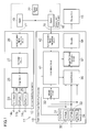
- FIG. 1 schematically illustrates a night vision image capturing system 11 according to one embodiment.
- the night vision image capturing system 11 includes an infrared radiating apparatus 12 and a night vision image capturing apparatus 13.
- the infrared radiating apparatus 12 emits, toward an object, an infrared radiation 14a having a first wavelength, an infrared radiation 14b having a second wavelength and an infrared radiation 14c having a third wavelength, for example.
- the night vision image capturing apparatus 13 captures images for the respective infrared radiations 14a, 14b, 14c.
- the intensity distribution of the infrared radiations 14a, 14b, 14c can be obtained for the individual images. Red (R), green (G) and blue (B) are respectively assigned to the individual images as display colors.
- red is assigned to the images generated based on the infrared radiation 14a having the first wavelength.
- Blue is assigned to the images generated based on the infrared radiation 14b having the second wavelength.
- Green is assigned to the images generated based on the infrared radiation 14c having the third wavelength.
- the superimposition of the intensity distributions of the assigned display colors results in a quasi color image having a natural tone.
- a display unit 15 may be connected to the night vision image capturing apparatus 13.
- the color image can be displayed on the screen of the display unit 15.
- a storage apparatus not depicted, may be connected to the night vision image capturing apparatus 13. The color image can be stored in the storage apparatus.
- the infrared radiating apparatus 12 and the night vision image capturing apparatus 13 are connected to a commercial power supply 16.
- the infrared radiating apparatus 12 and the night vision image capturing apparatus 13 respectively include power supply cords 17, 18.
- the plugs of the power supply cords 17, 18 are coupled to outlets 19, 21, respectively.
- the alternating current is supplied to the outlets 19, 21 from a generator of a power plant 22.
- the alternating current has a specific frequency such as 50Hz or 60Hz, for example.
- the infrared radiating apparatus 12 and the night vision image capturing apparatus 13 operate in response to the supply of the alternating current.
- the alternating current may optionally be converted to the direct current for the operation of the infrared radiation apparatus 12 and the night vision image capturing apparatus 13.
- AD/DC circuits may be incorporated in the infrared radiating apparatus 12 and the night vision image capturing apparatus 13. Electric power may be supplied to the outlets 19, 21 from a home generator, for example, in place of the generator of the power plant 22. Otherwise, electric power may be supplied to the outlets 19, 21 from a common generator in any form.
- the infrared radiating apparatus 12 includes a first infrared radiation illuminant 23, a second infrared radiation illuminant 24 and a third infrared radiation illuminant 25.
- the first infrared radiation illuminant 23 is configured to emit the infrared radiation 14a having the first wavelength for the peak intensity.
- the first wavelength may be set at 780nm, for example.
- the first infrared radiation illuminant 23 may comprise a light-emitting diode (LED), for example.
- the second infrared radiation illuminant 24 is configured to emit the infrared radiation 14b having the second wavelength for the peak intensity.
- the second wavelength is set longer than the first wavelength.
- the second wavelength may be set at 870nm, for example.
- the second infrared radiation illuminant 24 may comprise a light-emitting diode (LED), for example.
- the third infrared radiation illuminant 25 is configured to emit the infrared radiation 14c having the third wavelength for the peak intensity.
- the third wavelength is set longer than the second wavelength.
- the third wavelength may be set at 940nm, for example.
- the third infrared radiation illuminant 25 may comprise a light-emitting diode (LED), for example.
- the individual infrared radiation illuminants 23, 24, 25 may have the half value width of 40nm, for example.
- the infrared radiating apparatus 12 includes a driver circuit 26.
- the driver circuit 26 is connected to the first infrared radiation illuminant 23, the second infrared radiation illuminant 24 and the third infrared radiation illuminant 25.
- the driver circuit 26 is configured to supply driving signals to the first infrared radiation illuminant 23, the second infrared radiation illuminant 24 and the third infrared radiation illuminant 25, respectively.
- the infrared radiations 14a, 14b, 14c are respectively emitted from the first infrared radiation illuminant 23, the second infrared radiation illuminant 24 and the third infrared radiation illuminant 25 toward an object in response to the supply of the driving signals.
- the driving signals serve to determine the illuminating periods of the first, second and third infrared radiation illuminants 23, 24, 25. While the driving signals are not supplied, the first infrared radiation illuminant 23, the second infrared radiation illuminant 24 and the third infrared radiation illuminant 25 do not emit infrared radiations. The first infrared radiation illuminant 23, the second infrared radiation illuminant 24 and the third infrared radiation illuminant 25 are extinguished.
- the driving signals may be generated based on the direct current converted from the alternating current.
- the separate driver circuits 26 may be connected to the first infrared radiation illuminant 23, the second infrared radiation illuminant 24 and the third infrared radiation illuminant 25, respectively.
- the infrared radiating apparatus 12 includes a controller circuit 27.
- the controller circuit 27 is connected to the driver circuit 26.
- the controller circuit 27 is configured to supply control signals to the driver circuit 26.
- the controller circuit 27 serves to determine the illuminating period of the first infrared radiation illuminant 23, the illuminating period of the second infrared radiation illuminant 24 and the illuminating period of the third infrared radiation illuminant 25 in a predetermined sequence.
- the control signals enable the switchover of the emission of the infrared radiations 14a, 14b, 14c from the first infrared radiation illuminant 23, the second infrared radiation illuminant 24 and the third infrared radiation illuminant 25 in the predetermined sequence.
- the infrared radiating apparatus 12 includes a synchronization signal generating circuit 28.
- the synchronization signal generating circuit 28 is connected to the controller circuit 27.
- the alternating current is supplied to the synchronization signal generating circuit 28 from the outlet 19.
- the synchronization signal generating circuit 28 is configured to detect the zero crossing point of the alternating voltage.
- the synchronization signal generating circuit 28 serves to identify the phase of the alternating voltage in response to the detection of the zero crossing point.
- the synchronization signal generating circuit 28 generates a synchronization signal having a frequency of the alternating voltage in a manner synchronized with the phase of the alternating voltage.
- the synchronization signal is supplied to the controller circuit 27.
- the controller circuit 27 switches over the illumination of the first infrared radiation illuminant 23, the second infrared radiation illuminant 24 and the third infrared radiation illuminant 25 in a manner synchronized with the synchronization signal.
- the night vision image capturing apparatus 13 includes an imaging device 31.
- the imaging device 31 includes an array of pixels in a predetermined arrangement.
- the pixels are categorized in red color pixels (R pixels) 32, green color pixels (G pixels) 33 and blue color pixels (B pixels) 34.
- the red color pixels 32, the green color pixels 33 and the blue color pixels 34 may be arranged in accordance with the Bayer pattern, for example.
- the red color pixels 32 have the sensitivity to red of the primary color.
- the green color pixels 33 have the sensitivity to green of the primary color.
- the blue color pixels 34 have the sensitivity to blue of the primary color.
- An on-chip color filter may be formed on the individual pixels to establish the red color pixels 32, the green color pixels 33 and the blue color pixels 34.
- the individual pixels 32, 33, 34 are configured to output electric voltage corresponding to the intensity of the light or electromagnetic waves in a predetermined frequency band. Any of the pixels 32, 33, 34 has the sensitivity to the infrared radiation, in this case, to a near-infrared radiation. Accordingly, any of the pixels 32, 33, 34 outputs electric voltage in response to the reception of the infrared radiation.
- the intensity distribution can be detected for the light of the respective frequency bands.
- the intensity distribution forms an image signal.
- the imaging device 31 may comprise a solid-state imaging element such as a charge-coupled device (CCD) imaging sensor, a CMOS imaging sensor, and the like. The imaging device 31 is configured to generate images at predetermined periods.
- the night vision image capturing apparatus 13 includes an image memory 36.
- the image memory 36 is connected to the imaging device 31.
- the image memory 36 is configured to temporarily store image data.
- the individual image data serves to specify the image generated at the imaging device 31.
- the image memory 36 is configured to simultaneously hold the image data corresponding to at least three images, as described later in detail.
- the night vision image capturing apparatus 13 includes an image synthesis processing circuit 37.
- the image synthesis processing circuit 37 is connected to the image memory 36.
- the image synthesis processing circuit 37 is configured to obtain the image data from the image memory 36.
- the image synthesis processing circuit 37 synthesizes three temporally consecutive images into an image.
- the display colors are respectively assigned to the individual images in a predetermined sequence.
- the intensity distribution of the infrared radiation is converted into the intensity distribution of the display color in accordance with a predetermined rule.
- the rule may be derived from an experiment and/or actual measurements, for example.
- the conversion rules may be stored in an internal memory of the image synthesis processing circuit 37, for example. Here, red, blue and green line up in this sequence in a single period. Accordingly, the synthesis of three temporally consecutive images results in generation of a color image.
- the night vision image capturing apparatus 13 includes an encoder 38.
- the encoder 38 is connected to the image synthesis processing circuit 37.
- the image signals are supplied to the encoder 38 from the image synthesis processing circuit 37.
- the image signals specify color images.
- the encoder 38 is configured to convert the image signals into the composite signals for displaying equipment.
- the output signals of the encoder 38 may be supplied to the display unit 15 and/or the storage apparatus, for example.
- the night vision image capturing apparatus 13 includes an infrared discriminating circuit 39.
- the infrared discriminating circuit 39 is connected to the imaging device 31.
- the output (a "first signal” hereinafter) of the red color pixel 32, the output (a "second signal” hereinafter) of the blue color pixel 34 and the output of the green color pixel 33 are individually supplied to the infrared discriminating circuit 39.
- the infrared discriminating circuit 39 is configured to compare the first signal and the second signal with each other.
- the infrared discriminating circuit 39 enables discrimination of an infrared radiation having a specific wavelength, namely the infrared radiation 14a having the first wavelength, based on the ratio of the first signal and the second signal.
- the first signal and the second signal may be derived from a single one of the red color pixels 32 and a single one of the blue color pixels 34 located side by side, or the same number of the red color pixels 32 and the blue color pixels 34 in a predetermined local area, or the same number of the red color pixels 32 and the blue color pixels 34 in the entire imaging device 31.
- the night vision image capturing apparatus 13 includes a controlling circuit 41.
- the controlling circuit 41 is connected to the imaging device 31, the image memory 36, the image synthesis processing circuit 37 and the infrared discriminating circuit 39.
- the controlling circuit 41 is configured to supply a driving signal to the imaging device 31.
- the controlling circuit 41 outputs the vertical synchronizing signal or pulses to the imaging device 31 at predetermined periods.
- the imaging device 31 captures an image in a manner synchronized with the vertical synchronizing signal.
- the image memory 36 serves to hold the latest three image data in a manner synchronized with the output of the imaging device 31.
- the image memory 36 updates the image data every time the imaging device 31 outputs the image signal.
- the controlling circuit 41 supplies a control signal to the image synthesis processing circuit 37.
- the control signal is synchronized with the reception timing of the infrared radiation having a selected wavelength.
- the control signal is synchronized with the reception timing of the infrared radiation 14a having the first wavelength.
- the reception timing is determined based on the output of the infrared discriminating circuit 39.
- the image synthesis processing circuit 37 specifies which is the image resulting from the infrared radiation 14a having the first wavelength among the images stored in the image memory 36.
- the image resulting from the infrared radiation 14a having the first wavelength is identified in this manner, the image resulting from the infrared radiation 14b having the second wavelength and the image resulting from the infrared radiation 14c having the third wavelength can sequentially be identified since the infrared radiations 14a, 14b, 14c are emitted in a predetermined sequence.
- the night vision image capturing apparatus 13 includes a synchronization signal generating circuit 42.
- the synchronization signal generating circuit 42 is connected to the controlling circuit 41.
- the alternating current is supplied to the synchronization signal generating circuit 42 from the outlet 21.
- the synchronization signal generating circuit 42 is configured to detect the zero crossing point of the alternating voltage.
- the synchronization signal generating circuit 42 serves to identify the phase of the alternating voltage in response to the detection of the zero crossing point.
- the synchronization signal generating circuit 42 generates a synchronization signal having a frequency of the alternating voltage in a manner synchronized with the phase of the alternating voltage.
- the synchronization signal is supplied to the controlling circuit 41.
- the controlling circuit 41 controls the operation of the imaging device 31, the image memory 36 and the image synthesis processing circuit 37 in a manner synchronized with the synchronization signal.
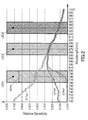
- the red color pixels 32, the green color pixels 33 and the blue color pixels 34 have different sensitivity to the infrared radiation depending on the wavelength of the infrared radiation.
- the difference of the sensitivity gets larger as the wavelength of the infrared radiation gets shorter.
- the red color pixels 32 exhibit a higher sensitivity to the infrared radiation 14a having the first wavelength than the green color pixels 33 and the blue color pixels 34 do.
- the red color pixels 32, the green color pixels 33 and the blue color pixels 34 exhibit a similar sensitivity to the infrared radiation 14b having the second wavelength and the infrared radiation 14c having the third wavelength.
- the relative sensitivity ratio between the first signal (the red color pixels 32) and the second signal (the blue color pixels 34) exceeds a predetermined value such that the ratio of the sensitivity to the first signal to the sensitivity to the second signal becomes equal to or larger than "2", for example, the corresponding image can be discriminated as an image resulting from the infrared radiation 14a having the first wavelength.
- the relative sensitivity ratio between the first signal and the second signal is close to "1 ", the corresponding image can be discriminated as images resulting from the infrared radiation 14b, 14c having the second or third wavelength.
- the output to the green color pixels 33 may be employed as the second signal in place of the blue color pixels 34.
- the infrared radiating apparatus 12 sequentially switches over the illumination of the first infrared radiation illuminant (LED1) 23, the second infrared radiation illuminant (LED2) 24 and the third infrared radiation illuminant (LED3).
- An object is sequentially irradiated with the infrared radiation 14a having the first wavelength, the infrared radiation 14b having the second wavelength and the infrared radiation 14c having the third wavelength.
- the synchronization signal generating circuit 28 generates the synchronization signal in a manner synchronized with the alternating current of the commercial power supply 16.
- the driving signals are respectively supplied from the driver circuit 26 to the first infrared radiation illuminant 23, the second infrared radiation illuminant 24 and the third infrared radiation illuminant 25 in this sequence in response to the leading edge or rise of the synchronization signal.
- the illuminating period of the first infrared radiation illuminant 23, the second infrared radiation illuminant 24 and the third infrared radiation illuminant 25 corresponds to one period of the commercial power supply 16.
- the infrared radiations 14a, 14b, 14c reflect from the object to the night vision image capturing apparatus 13 respectively during the corresponding illuminating periods.
- the reflected infrared radiations 14a, 14b, 14c are imaged on the imaging device 31 through a lens, not depicted.
- the night vision image capturing apparatus 13 captures the images of the infrared radiations 14a, 14b, 14c.
- the red color pixels 32, the green color pixels 33 and the blue color pixels 34 respectively output voltages corresponding to the intensities of the infrared radiations 14a, 14b, 14c.
- the magnitude of the voltages of the individual pixels 32, 33, 34 forms the intensity distribution for the respective infrared radiations 14a, 14b, 14c.
- the synchronization signal generating circuit 42 generates the synchronization signal in a manner synchronized with the alternating voltage of the commercial power supply 16.
- the imaging device 31 captures images in response to the leading edge or rise of the synchronization signal.
- the capturing period of the imaging device 31 corresponds to one period of the commercial power supply 16.
- the synchronization signal generating circuits 28, 42 are configured to generate the synchronization signal based on the common alternating voltage, the capturing action of the imaging device 31 is synchronized with the switchover of the infrared radiations 14a, 14b, 14c.
- the capturing periods of the imaging device 31 always coincides with any of the illuminating periods of the infrared radiation illuminants 23, 24, 25.
- the infrared discriminating circuit 39 compares the first signal and the second signal with each other for the individual images.
- the voltage of the red color pixel 32 and the voltage of the blue color pixel 34 are detected in a manner synchronized with the synchronization signal.
- the ratio is calculated of the first signal to the second signal. If the ratio is larger than a predetermined threshold, the infrared discriminating circuit 39 labels the image as the image resulting from the infrared radiation 14a having the first wavelength.
- the image synthesis processing circuit 37 assigns the red color of the display colors to the labeled image.
- the intensity distribution of the infrared radiation 14a having the first wavelength is converted into the intensity distribution of the red color.
- the image synthesis processing circuit 37 then assigns the blue color of the display colors to the subsequent image.
- the intensity distribution of the infrared radiation 14b having the second wavelength is converted into the intensity distribution of the blue color.
- the image synthesis processing circuit 37 thereafter assigns the green color of the display colors to the further subsequent image.
- the intensity distribution of the infrared radiation 14c having the third wavelength is converted into the intensity distribution of the green color.
- the intensity distribution of the red color, the intensity distribution of the blue color and the intensity distribution of the green color are superimposed on one another so as to generate a color image.
- Any one of the red color image, the green color image and the blue color image is updated at periods of the alternating current in response to the corresponding one of the infrared radiations 14a, 14b, 14c.
- the updated color image is combined with the non-updated color images resulting from the infrared radiations 14a, 14b, 14c having the other wavelengths, so that a color image is generated.
- the encoder 38 converts the image signals of the color images into the composite signals for displaying equipment.
- the composite signals are supplied to the display unit 15.
- the color images of the object are displayed on the screen of the display unit 15 in a relatively natural tone.
- the inventor has observed a change in the relative sensitivity ratio between the first signal and the second signal depending on the wavelength of the infrared radiations 14a, 14b, 14c. Accordingly, when the relative sensitivity ratio between the first signal and the second signal exceeds the predetermined threshold at the infrared discriminating circuit 39, the reception timing can be discriminated for the infrared radiation 14a having the first wavelength. Since the infrared radiations 14a, 14b, 14c are received in the predetermined sequence, the discrimination of the reception timing of the infrared radiation 14a having the first wavelength results in determination of the reception timings for all the infrared radiations 14a, 14b, 14c.
- the red color, the blue color and the green color can reliably be related to the images of the infrared radiation 14a having the first wavelength, the images of the infrared radiation 14b having the second wavelength and the images of the infrared radiation 14c having the third wavelength.
- the infrared radiating apparatus 12 and the night vision image capturing apparatus 13 receive the electric power from the outlets 19, 21, respectively, during their operations.
- the outlets 19, 21 enable the supply of the electric power of the identical phase not only to the night vision image capturing apparatus 13 but also to the infrared radiating apparatus 12.
- the capturing timings of the imaging device 31 can be synchronized with the switchover of the infrared radiations 14a, 14b, 14c having the different wavelengths. Synchronization can be accomplished without a direct control line between the infrared radiating apparatus 12 and the night vision image capturing apparatus 13. Accordingly, the infrared radiating apparatus 12 and the night vision image capturing apparatus 13 can be placed at remote locations from each other without any restrictions for installation and arrangements. Any supplementary infrared radiating apparatus 12 and/or night vision image capturing apparatus 13 may be added into the night vision image capturing system 11 in a facilitated manner.
- the night vision image capturing apparatus 13 assigns the red color as one of the display colors to the image signals resulting from the infrared radiation 14a having the first wavelength.
- the blue color is assigned as one of the display colors to the image signals resulting from the infrared radiation 14b having the second wavelength longer than the first wavelength.
- the green color is assigned as one of the display colors to the image signals resulting from the infrared radiation 14c having the third wavelength longer than the second wavelength.
- the red color may be assigned to the image signals resulting from the infrared radiation 14a having the first wavelength
- the green color may be assigned to the image signals resulting from the infrared radiation 14b having the second wavelength
- the blue color may be assigned to the image signals resulting from the infrared radiation 14c having the third wavelength.
- the relative sensitivity ratio gets to "1". Accordingly, the comparison of the voltage between the red color and the blue color enables a reliable discrimination of the reception timing of the infrared radiation 14a having the first wavelength.
- the comparison of the voltage between the red color and the green color, in place of the blue color also enables discrimination of the reception timing of the infrared radiation 14a having the first wavelength.
- the night vision image capturing system 11 may employ oscillators in place of the synchronization signal generating circuits 28, 42. Any quartz crystal oscillator may be employed as the oscillator, for example. A frequency divider may be combined with the quartz crystal oscillator. The oscillators may generate local synchronization signals for the infrared radiating apparatus 12 and the night vision image capturing apparatus 13. If oscillators having a predetermined frequency are incorporated into the infrared radiating apparatus 12 and the night vision image capturing apparatus 13, respectively, the period of the switchover of the infrared radiations 14a, 14b, 14c coincides with the period of the capture of the images.
- the timing of a change is derived for the ratio of the sensitivity between the red color pixel 32 and the blue color pixel 34, the timing is discovered for the beginning of the infrared radiation 14a having the first wavelength or the beginning of the infrared radiation 14b having the second wavelength.
- the red color, the blue color and the green color as the display colors can in this manner be assigned to the images resulting from the infrared radiations 14a, 14b, 14c, respectively.
- the infrared discriminating circuit 39 is preferably configured to compare the first signal and the second signal with each other in a period sufficiently shorter than the period for the switchover and the capture of the images.
- the night vision image capturing system 11 may be utilized as a security camera system.
- the night vision image capturing apparatus 13 in the security camera system may function as a day/night camera capable of receiving a visible radiation to capture images in the daytime and of receiving a visible radiation and an infrared radiation to capture images in the nighttime.
- An infrared cut filter may be combined with the imaging device 31 so as to realize the day/night camera, for example.
- the infrared cut filter serves to cut off the infrared radiations directed toward the imaging device 31 during the capture of images.
- the individual red color pixels 32 output the voltage corresponding to the intensity of the red light
- the individual green color pixels 33 output the voltage corresponding to the intensity of the green light
- the individual blue color pixels 34 output the voltage corresponding to the intensity of the blue light.
- a single capturing action possibly results in generation of a color image.
- the infrared cut filter is removed during the night vision image capturing action.
- the infrared cut filter may removably be disposed in an optical path between the lens and the imaging device 31.
- a driving mechanism may be connected to the infrared cut filter for insertion and withdrawal of the infrared cut filter.
- An imaging device includes pixels configured to sequentially output image signals for an infrared radiation having a first wavelength, an infrared radiation having a second wavelength and an infrared radiation having a third wavelength.
- a first pixel has the sensitivity to a first color of a primary color and outputting a first signal in response to reception of the infrared radiation having the shortest wavelength of the first wavelength, the second wavelength and the third wavelength.
- a second pixel has the sensitivity to a second color of the primary color and outputting a second signal in response to the reception of the infrared radiation having the shortest wavelength.
- a discriminating circuit is configured to compare the first signal and the second signal with each other to discriminate a reception timing of an infrared radiation having a selected wavelength in response to a relative sensitivity ratio.
Landscapes
- Engineering & Computer Science (AREA)
- Multimedia (AREA)
- Signal Processing (AREA)
- Physics & Mathematics (AREA)
- Spectroscopy & Molecular Physics (AREA)
- Color Television Image Signal Generators (AREA)
- Studio Devices (AREA)
- Transforming Light Signals Into Electric Signals (AREA)
Applications Claiming Priority (1)
| Application Number | Priority Date | Filing Date | Title |
|---|---|---|---|
| JP2012116569A JP6011778B2 (ja) | 2012-05-22 | 2012-05-22 | 暗視撮像装置および赤外線照射装置および暗視撮像システム |
Publications (2)
| Publication Number | Publication Date |
|---|---|
| EP2667588A2 true EP2667588A2 (fr) | 2013-11-27 |
| EP2667588A3 EP2667588A3 (fr) | 2013-12-11 |
Family
ID=46650358
Family Applications (1)
| Application Number | Title | Priority Date | Filing Date |
|---|---|---|---|
| EP12173924.7A Withdrawn EP2667588A3 (fr) | 2012-05-22 | 2012-06-27 | Appareil de capture d'image de vision nocturne et appareil à rayonnement infrarouge et système de capture d'image de vision nocturne |
Country Status (4)
| Country | Link |
|---|---|
| US (1) | US20130314544A1 (fr) |
| EP (1) | EP2667588A3 (fr) |
| JP (1) | JP6011778B2 (fr) |
| CN (1) | CN103428505A (fr) |
Cited By (2)
| Publication number | Priority date | Publication date | Assignee | Title |
|---|---|---|---|---|
| CN105744241A (zh) * | 2016-04-07 | 2016-07-06 | 珠海格力电器股份有限公司 | 一种拍摄方法、拍摄装置及电子设备 |
| US10482361B2 (en) | 2015-07-05 | 2019-11-19 | Thewhollysee Ltd. | Optical identification and characterization system and tags |
Families Citing this family (30)
| Publication number | Priority date | Publication date | Assignee | Title |
|---|---|---|---|---|
| US9071740B1 (en) | 2011-10-28 | 2015-06-30 | Google Inc. | Modular camera system |
| US9197686B1 (en) | 2012-01-06 | 2015-11-24 | Google Inc. | Backfill of video stream |
| US9537968B1 (en) | 2012-01-06 | 2017-01-03 | Google Inc. | Communication of socket protocol based data over a storage protocol based interface |
| JP2014241584A (ja) * | 2013-05-14 | 2014-12-25 | パナソニックIpマネジメント株式会社 | 画像処理方法、及び画像処理システム |
| JP6160546B2 (ja) * | 2013-11-25 | 2017-07-12 | 株式会社Jvcケンウッド | 映像処理装置、撮像装置、映像処理方法、及び映像処理プログラム |
| JP6318789B2 (ja) * | 2013-11-25 | 2018-05-09 | 株式会社Jvcケンウッド | 映像処理装置、映像処理方法、及び映像処理プログラム |
| JP6264029B2 (ja) * | 2013-12-26 | 2018-01-24 | 株式会社Jvcケンウッド | 撮像装置、撮像装置の制御方法及び制御プログラム |
| JP6136948B2 (ja) * | 2014-01-24 | 2017-05-31 | 株式会社Jvcケンウッド | 撮像装置、映像信号処理方法及び映像信号処理プログラム |
| WO2015118911A1 (fr) * | 2014-02-06 | 2015-08-13 | 株式会社Jvcケンウッド | Dispositif de capture d'image, son procédé de commande, système de capture d'image et son procédé de commande |
| JP6183238B2 (ja) * | 2014-02-06 | 2017-08-23 | 株式会社Jvcケンウッド | 撮像装置及び撮像装置の制御方法 |
| JP6090191B2 (ja) * | 2014-02-06 | 2017-03-08 | 株式会社Jvcケンウッド | 撮像装置及び撮像装置の制御方法 |
| JP6090217B2 (ja) * | 2014-03-26 | 2017-03-08 | 株式会社Jvcケンウッド | 撮像システム及び撮像システムの制御方法 |
| DE112015001741T5 (de) * | 2014-04-08 | 2016-12-29 | Tk Holdings Inc. | System und Verfahren für Nachtvisionsobjektdetektion und Fahrerassistenz |
| JP5655969B1 (ja) * | 2014-07-01 | 2015-01-21 | 株式会社Jvcケンウッド | 撮像装置、撮像装置の制御方法及び制御プログラム |
| JP5692446B1 (ja) * | 2014-07-01 | 2015-04-01 | 株式会社Jvcケンウッド | 撮像装置、撮像装置の制御方法及び制御プログラム |
| JP6264234B2 (ja) * | 2014-09-02 | 2018-01-24 | 株式会社Jvcケンウッド | 撮像装置、撮像装置の制御方法及び制御プログラム |
| JP6264233B2 (ja) * | 2014-09-02 | 2018-01-24 | 株式会社Jvcケンウッド | 撮像装置、撮像装置の制御方法及び制御プログラム |
| JP6633268B2 (ja) * | 2014-09-03 | 2020-01-22 | グローリー株式会社 | センサモジュール及び紙葉類処理装置 |
| DE102014217750A1 (de) * | 2014-09-04 | 2016-03-10 | Conti Temic Microelectronic Gmbh | Kamerasystem und Verfahren zur Umfelderfassung eines Fahrzeugs |
| US9544485B2 (en) | 2015-05-27 | 2017-01-10 | Google Inc. | Multi-mode LED illumination system |
| US9886620B2 (en) | 2015-06-12 | 2018-02-06 | Google Llc | Using a scene illuminating infrared emitter array in a video monitoring camera to estimate the position of the camera |
| US9613423B2 (en) | 2015-06-12 | 2017-04-04 | Google Inc. | Using a depth map of a monitored scene to identify floors, walls, and ceilings |
| US9626849B2 (en) | 2015-06-12 | 2017-04-18 | Google Inc. | Using scene information from a security camera to reduce false security alerts |
| US9454820B1 (en) * | 2015-06-12 | 2016-09-27 | Google Inc. | Using a scene illuminating infrared emitter array in a video monitoring camera for depth determination |
| US9489745B1 (en) | 2015-06-12 | 2016-11-08 | Google Inc. | Using depth maps of a scene to identify movement of a video camera |
| US9235899B1 (en) | 2015-06-12 | 2016-01-12 | Google Inc. | Simulating an infrared emitter array in a video monitoring camera to construct a lookup table for depth determination |
| US9554063B2 (en) | 2015-06-12 | 2017-01-24 | Google Inc. | Using infrared images of a monitored scene to identify windows |
| US9386230B1 (en) | 2015-06-12 | 2016-07-05 | Google Inc. | Day and night detection based on one or more of illuminant detection, lux level detection, and tiling |
| US10180615B2 (en) | 2016-10-31 | 2019-01-15 | Google Llc | Electrochromic filtering in a camera |
| JP7005317B2 (ja) * | 2017-12-04 | 2022-01-21 | キヤノン株式会社 | 撮像装置、撮像装置の制御方法およびプログラム |
Citations (1)
| Publication number | Priority date | Publication date | Assignee | Title |
|---|---|---|---|---|
| JP2011050049A (ja) | 2009-07-30 | 2011-03-10 | National Institute Of Advanced Industrial Science & Technology | 画像撮影装置および画像撮影方法 |
Family Cites Families (11)
| Publication number | Priority date | Publication date | Assignee | Title |
|---|---|---|---|---|
| JPS5952228A (ja) * | 1982-09-17 | 1984-03-26 | Sharp Corp | 複写装置の駆動方式 |
| JPH047991A (ja) * | 1990-04-25 | 1992-01-13 | Sony Corp | 暗視カラー撮像装置 |
| JP3485623B2 (ja) * | 1994-03-28 | 2004-01-13 | 三洋電機株式会社 | ビデオカメラ |
| JP4782277B2 (ja) * | 2000-11-29 | 2011-09-28 | 株式会社ユーテック | 赤外線カラー画像形成装置 |
| JP4839432B2 (ja) * | 2003-12-17 | 2011-12-21 | 国立大学法人静岡大学 | 瞳孔位置検出によるポインティング装置及び方法 |
| JP4630781B2 (ja) * | 2005-09-26 | 2011-02-09 | キヤノン株式会社 | 波長成分の割合検出装置及びそれを用いた撮像装置 |
| CN100579324C (zh) * | 2006-11-24 | 2010-01-06 | 安提亚科技股份有限公司 | 可同步控制及切换变化模式的led变色装置 |
| JP4407707B2 (ja) * | 2007-03-02 | 2010-02-03 | 日産自動車株式会社 | 撮像装置、画像表示システム、撮像装置の制御方法 |
| US8810651B2 (en) * | 2007-09-26 | 2014-08-19 | Honeywell International, Inc | Pseudo-color covert night vision security digital camera system |
| CN201388319Y (zh) * | 2009-02-27 | 2010-01-20 | 上海宝康电子控制工程有限公司 | 可多种同步的led光源控制装置 |
| KR101072901B1 (ko) * | 2009-11-06 | 2011-10-17 | 박경아 | 엘이디 조명장치용 스위칭 시스템의 무선통신 제어방법 |
-
2012
- 2012-05-22 JP JP2012116569A patent/JP6011778B2/ja not_active Expired - Fee Related
- 2012-06-27 US US13/535,347 patent/US20130314544A1/en not_active Abandoned
- 2012-06-27 EP EP12173924.7A patent/EP2667588A3/fr not_active Withdrawn
- 2012-09-10 CN CN2012103336091A patent/CN103428505A/zh active Pending
Patent Citations (1)
| Publication number | Priority date | Publication date | Assignee | Title |
|---|---|---|---|---|
| JP2011050049A (ja) | 2009-07-30 | 2011-03-10 | National Institute Of Advanced Industrial Science & Technology | 画像撮影装置および画像撮影方法 |
Cited By (2)
| Publication number | Priority date | Publication date | Assignee | Title |
|---|---|---|---|---|
| US10482361B2 (en) | 2015-07-05 | 2019-11-19 | Thewhollysee Ltd. | Optical identification and characterization system and tags |
| CN105744241A (zh) * | 2016-04-07 | 2016-07-06 | 珠海格力电器股份有限公司 | 一种拍摄方法、拍摄装置及电子设备 |
Also Published As
| Publication number | Publication date |
|---|---|
| JP6011778B2 (ja) | 2016-10-19 |
| EP2667588A3 (fr) | 2013-12-11 |
| JP2013243589A (ja) | 2013-12-05 |
| CN103428505A (zh) | 2013-12-04 |
| US20130314544A1 (en) | 2013-11-28 |
Similar Documents
| Publication | Publication Date | Title |
|---|---|---|
| EP2667588A2 (fr) | Appareil de capture d'image de vision nocturne et appareil à rayonnement infrarouge et système de capture d'image de vision nocturne | |
| US10419693B2 (en) | Imaging apparatus, endoscope apparatus, and microscope apparatus | |
| US9148581B2 (en) | Multi-function control illumination device | |
| US9860521B2 (en) | Image processing system | |
| JP4316629B2 (ja) | 画像処理システム、画像取得方法及びプログラム | |
| US10171759B2 (en) | Imaging device, method for controlling imaging device, imaging system, and method for controlling imaging system | |
| US20100254692A1 (en) | Camera illumination device | |
| KR20110065530A (ko) | 복수의 광원의 자동 커미셔닝을 위한 시스템 및 방법 | |
| JP2022097664A (ja) | 可視光通信システム | |
| US9451667B2 (en) | Optical sensor circuit, luminous panel and method of operating an optical sensor circuit | |
| US9961276B2 (en) | Camera apparatus and image processing method | |
| JP5989284B1 (ja) | 撮像システム及び光源装置 | |
| RU2447471C2 (ru) | Цветная последовательная вспышка для получения цифровых изображений | |
| WO2010049578A1 (fr) | Traitement vidéo | |
| KR20210049853A (ko) | 광통신 장치 및 정보 송수신 방법 | |
| US9319575B2 (en) | Illumination apparatus with integrated power provision | |
| US20110221899A1 (en) | Lighting apparatus and lighting control method for a closed-circuit television camera, and lighting control system interlocked with the closed-circuit television camera | |
| KR101101779B1 (ko) | 폐쇄회로텔레비젼 카메라 연동형 조명 제어시스템 | |
| KR101524278B1 (ko) | 기준광원을 이용한 카메라 통신 시스템 및 통신 방법 | |
| KR101201781B1 (ko) | 차량번호 식별이 용이한 씨씨티브이용 카메라의 조명제어장치 | |
| JP4969336B2 (ja) | カメラおよびカメラを用いた監視装置 | |
| JP2015216629A (ja) | リモコン信号認識機、リモコン信号認識システム、電気機器システム、及びリモコン信号認識プログラム | |
| JP2015073208A (ja) | 撮像装置、情報表示装置及び情報処理システム | |
| US9219892B2 (en) | Camera apparatus and image processing method with synchronous detection processing | |
| WO2019003361A1 (fr) | Dispositif et système d'imagerie |
Legal Events
| Date | Code | Title | Description |
|---|---|---|---|
| PUAL | Search report despatched |
Free format text: ORIGINAL CODE: 0009013 |
|
| PUAI | Public reference made under article 153(3) epc to a published international application that has entered the european phase |
Free format text: ORIGINAL CODE: 0009012 |
|
| AK | Designated contracting states |
Kind code of ref document: A2 Designated state(s): AL AT BE BG CH CY CZ DE DK EE ES FI FR GB GR HR HU IE IS IT LI LT LU LV MC MK MT NL NO PL PT RO RS SE SI SK SM TR |
|
| AX | Request for extension of the european patent |
Extension state: BA ME |
|
| AK | Designated contracting states |
Kind code of ref document: A3 Designated state(s): AL AT BE BG CH CY CZ DE DK EE ES FI FR GB GR HR HU IE IS IT LI LT LU LV MC MK MT NL NO PL PT RO RS SE SI SK SM TR |
|
| AX | Request for extension of the european patent |
Extension state: BA ME |
|
| RIC1 | Information provided on ipc code assigned before grant |
Ipc: H04N 5/235 20060101ALI20131101BHEP Ipc: H04N 5/33 20060101AFI20131101BHEP |
|
| STAA | Information on the status of an ep patent application or granted ep patent |
Free format text: STATUS: THE APPLICATION IS DEEMED TO BE WITHDRAWN |
|
| 18D | Application deemed to be withdrawn |
Effective date: 20140612 |