EP2667408A2 - Kühlvorrichtung mit natürlicher Zirkulation - Google Patents
Kühlvorrichtung mit natürlicher Zirkulation Download PDFInfo
- Publication number
- EP2667408A2 EP2667408A2 EP12183408.9A EP12183408A EP2667408A2 EP 2667408 A2 EP2667408 A2 EP 2667408A2 EP 12183408 A EP12183408 A EP 12183408A EP 2667408 A2 EP2667408 A2 EP 2667408A2
- Authority
- EP
- European Patent Office
- Prior art keywords
- coolant
- heat
- condenser
- radiator
- cooling apparatus
- Prior art date
- Legal status (The legal status is an assumption and is not a legal conclusion. Google has not performed a legal analysis and makes no representation as to the accuracy of the status listed.)
- Granted
Links
Images





Classifications
-
- H—ELECTRICITY
- H10—SEMICONDUCTOR DEVICES; ELECTRIC SOLID-STATE DEVICES NOT OTHERWISE PROVIDED FOR
- H10W—GENERIC PACKAGES, INTERCONNECTIONS, CONNECTORS OR OTHER CONSTRUCTIONAL DETAILS OF DEVICES COVERED BY CLASS H10
- H10W40/00—Arrangements for thermal protection or thermal control
- H10W40/70—Fillings or auxiliary members in containers or in encapsulations for thermal protection or control
- H10W40/73—Fillings or auxiliary members in containers or in encapsulations for thermal protection or control for cooling by change of state
-
- F—MECHANICAL ENGINEERING; LIGHTING; HEATING; WEAPONS; BLASTING
- F28—HEAT EXCHANGE IN GENERAL
- F28D—HEAT-EXCHANGE APPARATUS, NOT PROVIDED FOR IN ANOTHER SUBCLASS, IN WHICH THE HEAT-EXCHANGE MEDIA DO NOT COME INTO DIRECT CONTACT
- F28D15/00—Heat-exchange apparatus with the intermediate heat-transfer medium in closed tubes passing into or through the conduit walls ; Heat-exchange apparatus employing intermediate heat-transfer medium or bodies
- F28D15/02—Heat-exchange apparatus with the intermediate heat-transfer medium in closed tubes passing into or through the conduit walls ; Heat-exchange apparatus employing intermediate heat-transfer medium or bodies in which the medium condenses and evaporates, e.g. heat pipes
- F28D15/0266—Heat-exchange apparatus with the intermediate heat-transfer medium in closed tubes passing into or through the conduit walls ; Heat-exchange apparatus employing intermediate heat-transfer medium or bodies in which the medium condenses and evaporates, e.g. heat pipes with separate evaporating and condensing chambers connected by at least one conduit; Loop-type heat pipes; with multiple or common evaporating or condensing chambers
-
- H—ELECTRICITY
- H05—ELECTRIC TECHNIQUES NOT OTHERWISE PROVIDED FOR
- H05K—PRINTED CIRCUITS; CASINGS OR CONSTRUCTIONAL DETAILS OF ELECTRIC APPARATUS; MANUFACTURE OF ASSEMBLAGES OF ELECTRICAL COMPONENTS
- H05K7/00—Constructional details common to different types of electric apparatus
- H05K7/20—Modifications to facilitate cooling, ventilating, or heating
- H05K7/2029—Modifications to facilitate cooling, ventilating, or heating using a liquid coolant with phase change in electronic enclosures
- H05K7/20327—Accessories for moving fluid, for connecting fluid conduits, for distributing fluid or for preventing leakage, e.g. pumps, tanks or manifolds
-
- H—ELECTRICITY
- H05—ELECTRIC TECHNIQUES NOT OTHERWISE PROVIDED FOR
- H05K—PRINTED CIRCUITS; CASINGS OR CONSTRUCTIONAL DETAILS OF ELECTRIC APPARATUS; MANUFACTURE OF ASSEMBLAGES OF ELECTRICAL COMPONENTS
- H05K7/00—Constructional details common to different types of electric apparatus
- H05K7/20—Modifications to facilitate cooling, ventilating, or heating
- H05K7/2089—Modifications to facilitate cooling, ventilating, or heating for power electronics, e.g. for inverters for controlling motor
- H05K7/20936—Liquid coolant with phase change
Definitions
- Embodiments described herein relate generally to a cooling apparatus applied with a natural circulation liquid cooling method, in which a coolant circulation pump for providing an external driving force is not used, and which cools an exothermic body such as a semiconductor device that is used in a power converter for a railway vehicle.
- a power converter for a railway vehicle comprises an exothermic body such as a semiconductor device, and a cooling apparatus for cooling such an exothermic body.
- a cooling method of a large-capacity cooling apparatus a boiling cooling method and a forced circulation liquid cooling method are applied.
- a cooling apparatus to which the former cooling method is applied there are, because of the device structure, such restrictions on disposition that a high-temperature unit is disposed on a lower side and a low-temperature unit is disposed on an upper side.
- a heat exchanger for condensing a generated vapor is disposed on an upper side of a heat receiver to which the exothermic body is attached, and a radiator is disposed on a lateral side of the heat receiver.
- a natural circulation type cooling apparatus comprises: a heat receiver comprising a heat receiving surface on which an exothermic body is mounted, and containing therein a coolant in a liquid phase; a condenser provided on a horizontally lateral side of the heat receiver, and configured to condense a vapor which is generated by the heat receiver; a radiator disposed on a horizontally lateral side of the heat receiver and on a vertically downward side of the condenser, and configured to cool the coolant which is fed from the heat receiver and is heated; a vapor conduit configured to feed the vapor of the coolant, which is generated by the heat receiver, to an inlet of the condenser; a condensed liquid conduit configured to feed the coolant, which is condensed, from an outlet of the condenser to a coolant inlet of the heat receiver; a coolant conduit configured to feed the coolant, which is heated in the heat receiver,
- FIG. 1 and FIG. 2 are, respectively, a side view and a plan view which schematically illustrate a railway vehicle including a natural circulation type cooling apparatus according to a first embodiment.
- the railway vehicle comprises a truck 12 provided with wheels 14, and a vehicle body 16 supported on the truck 12.
- a traction motor 18 is mounted on the truck 12 in the vicinity of the wheels 14.
- the traction motor 18 transmits a torque to the wheels 14 via a gear box and a coupling, which are not shown.
- the wheels 14 are placed on rails 13.
- Various devices including a power converter 20 are equipped under the floor of the vehicle body 16.
- a natural circulation type cooling apparatus 10 according to the embodiment is configured, for example, as a cooling apparatus for cooling semiconductor devices (exothermic body) which constitute the power converter 20, and is disposed under the floor of the vehicle body 16.
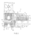
- FIG. 3 is a front view schematically showing the structure of the entirety of the cooling apparatus 10.
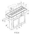
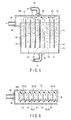
- FIG. 4 , FIG. 5 and FIG. 6 are, respectively, a perspective view and cross-sectional views showing a heat receiver of the cooling apparatus 10.
- the cooling apparatus 10 comprises a heat receiver 22 which cools semiconductor devices by receiving heat from the semiconductor devices, a condenser 24, a radiator 26, and a plurality of conduits which interconnect these components.
- the cooling apparatus 10 further comprises an air blower 28.
- the heat receiver 22 is provided, for example, within a housing 21 of the power converter 20, and is positioned in a substantially vertical plane.
- the condenser 24 and radiator 26 are arranged in the vertical plane common with the heat receiver 22, or in another vertical plane parallel to this vertical plane.
- the condenser 24 is provided on a horizontally lateral side of the heat receiver 22.
- the radiator 26 is arranged on the horizontally lateral side of the heat receiver 22, and on a vertically downward side of the condenser 24.
- the air blower 28 is opposed to the rear side of the condenser 24 and radiator 26.
- the heat receiver 22 includes a container body 30 having an elongated rectangular box shape, and an upper container 32 of a rectangular box shape, which covers an upper part of the container body 30 and forms a sub-flow passage which will be described later.
- a heat receiving surface 30a One or both of major surfaces of the container body 30 constitute a heat receiving surface 30a.
- a plurality of semiconductor devices 36 for example, two semiconductor devices 36, which are exothermic bodies, are mounted on the heat receiving surface 30a.
- the semiconductor devices 36 constitute a part of the power converter 20.
- the container body 30 is formed in a predetermined size in accordance with the cooling capability of the cooling apparatus, and a predetermined amount of liquid-phase coolant 34 is sealed in the container body 30.
- the coolant 34 use is made of pure water, a hydrocarbon-based coolant, an ammonia aqueous solution, an antifreeze liquid (ethylene glycol aqueous solution, propylene glycol aqueous solution, etc.), or a heat-accumulation microcapsule.
- a chemically stable coolant is used, and the coolant preferably has thermophysical properties of high evaporation latent heat and thermal conductivity, and a low viscosity coefficient.
- the material for forming the heat receiving surface 30a of the heat receiver 22 aluminum or brass is used in accordance with the coolant that is applied.
- a plurality of partition plates 38 are provided in the container body 30 of the heat receiver 22, so as to form desired flow passages or containing chambers.
- the partition plates 38 are arranged in the vertical direction within the container body 30, and at predetermined intervals in the horizontal direction.
- Containing chambers 40 which contain the coolant 34, or passages, are formed between mutually neighboring partition plates 38 or between the partition plates and side walls of the container body 30.
- a lower end of each partition plate 38 is slightly spaced apart from a bottom wall of the container body 30, and thereby the plural containing chambers 40 communicate with each other in the lower part within the container body 30.
- each partition plate 38 extends upward, beyond an upper opening 30b of the container body 30, and is located within the upper container 32.
- the upper end portions of the partition plates 38 form baffle pates 42.
- the baffle plates 42 restrain the coolant 34, which flows out of each containing chamber 40 of the container body 30, from flowing into the neighboring containing chambers 40.
- the structure of the baffle plate 42 is not limited to the structure in which the baffle plate 42 is formed integral with the partition plate 38.
- the baffle plate 42 may be configured such that a separately formed baffle plate is fixed to the partition plate 38.
- a sub-flow passage 44 is formed around the upper opening 30b of the container body 30.
- the coolant 34 which is heated and flows out of each containing chamber 40, flows into the sub-flow passage 44, and is fed to a coolant outlet (to be described later) through the sub-flow passage 44.
- the sub-flow passage 44 may be configured to be inclined at a desired angle to the coolant outlet side, so that the coolant may efficiently be fed to the coolant outlet.
- a vapor exhaust port 46 is formed in a ceiling wall of the upper container 32, and this vapor exhaust port 46 communicates with the plural containing chambers 40 via a space within the upper container 32.
- a coolant outlet 48 is formed in a side wall of the upper container 32, and this coolant outlet 48 communicates with the sub-flow passage 44.
- a coolant inlet 50 is formed in a bottom wall of the container body 30, and this coolant inlet 50 communicates with the plural containing chambers 40.
- the condenser 24 includes a conduit 52 which extends in a bellows shape and flows vapor, and a plurality of radiation fins 54 which are disposed directly or indirectly on the periphery of the conduit 52.
- the conduit 52 includes an inlet 56a which is located at one end of the conduit 52, and an outlet 56b which is located at the other end of the conduit 52.
- the outlet 56b is located on a vertically downward side of the inlet 56a.
- the inlet 56a of the conduit 52 is connected to the vapor exhaust port 46 of the heat receiver 22 via a vapor conduit 58.
- the outlet 56b of the conduit 52 is directly connected to the coolant inlet 50 of the heat receiver 22 via a condensed liquid conduit 60, or is connected to the coolant inlet 50 via a coolant circulation conduit 70 (to be described later).
- the condenser 24 cools the vapor which flows in the conduit 52, condenses the vapor into a coolant liquid, and discharges the coolant liquid from the outlet 56b to the condensed liquid conduit 60.
- the discharged coolant liquid is returned to the heat receiver 22 through the condensed liquid conduit 60.
- the condenser 24 may be configured or shaped such that the inside of the condenser 24 is coated with a paint with high water repellency in order to promote heat transfer with condensation, and an inclination is provided make it easier for the generated condensed liquid to flow downward.
- the radiator 26 includes a plurality of radiation tubes 62 which extend in the vertical direction and are juxtaposed in the horizontal direction, an inflow portion 64a which communicates with lower ends of the radiation tubes 62, an outflow portion 64b which communicates with upper ends of the radiation tubes 62, an inlet 66a which is provided at the inflow portion 64a, and an outlet 66b which is provided at the outflow portion 64b.
- Radiation fins may be provided on peripheries of the radiation tubes 62.
- the inlet 66a of the inflow portion 64a is connected to the coolant outlet 48 of the heat receiver 22 via a coolant conduit 68.
- the inlet 66a is located on a vertically downward side of the coolant outlet 48 of the heat receiver 22.
- the outlet 66b of the outflow portion 46b is connected to the coolant inlet 50 of the heat receiver 22 via the coolant circulation conduit 70.
- the radiator 26 flows the coolant upward from the inflow portion 64a through the plural radiation tubes 62 and, during this time, releases the heat of the coolant to the outside air and cools the coolant via the radiation tubes. Further, the radiator 26 feeds out the cooled coolant to the coolant circulation conduit 70 via the outflow portion 64b. The discharged coolant is returned to the heat receiver 22 through the coolant circulation conduit 70.
- the condensed liquid conduit 60 is connected to an intermediate portion of the coolant circulation conduit 70. Thereby, the coolant liquid, which has been discharged from the condenser 24, is fed to the heat receiver 22 via the condensed liquid conduit 60 and coolant circulation conduit 70.
- the air blower 28 is disposed to be opposed to the rear side of the condenser 24 and radiator 26, and the air blower 28 may be configured to be directly attached to the condenser 24 and radiator 26, or may be configured to be connected to the condenser 24 and radiator 26 via an air duct 72.
- the air blower 28 feeds a cooling wind to the condenser 24 and radiator 26, and facilitates cooling of the condenser 24 and radiator 26.
- the air duct 72 is disposed, the amount of air of the air blower 28 can be increased.
- the condenser 24 and radiator 26 may be configured to be disposed in a manner to protrude to the outside of the vehicle body, thereby to make use of a traveling wind, which is caused by traveling, as a cooling wind.
- the coolant 34 when the semiconductor devices 36 mounted on the heat receiving surface 30a of the heat receiver 22 are activated and produce heat, the heat conducts through the heat receiving surface 30a and heats, by heat transfer, the coolant 34 that is sealed in the container body 30 of the heat receiver 22. As the amount of loss in the semiconductor devices 36 increases, the coolant 34 reaches a saturation temperature and starts boiling. Bubbles 101, which are generated by boiling, produce a driving force by a difference in density from an ambient liquid. Specifically, buoyancy by the bubbles 101 generates an upward stream in the container body 30. With the bubbles 101 rising, the ambient coolant 34 also rises accordingly. In the upper part of the container body 30, the coolant 34 has a mixed phase of a gas phase and a liquid phase, that is, a gas/liquid two-phase fluid state.
- a vapor 102 which is generated by the heat receiver 22, is fed to the condenser 24 via the vapor conduit 58.
- heat exchange is performed by the radiation fins 54 that are disposed on the periphery thereof, and the vapor 102 is condensed into liquid.
- the condensed liquid of coolant is fed to the lower part of the heat receiver 22 via the condensed liquid conduit 60 and coolant circulation conduit 70.
- the high-temperature, gas/liquid two-phase coolant 34 at the upper part of the heat receiver 22 flows out of the upper opening 30b of the container body 30, with the upward stream thereof becoming a circulation driving stream.
- the outflow coolant 34 is guided to the sub-flow passage 44, and is further fed to the inflow portion 64a of the radiator 26 from the sub-flow passage 44 via the coolant conduit 68.
- the baffle plates 42 which are provided at the upper part of the container body 30, prevent the high-temperature coolant from flowing back into the heat receiver, that is, from flowing back into the neighboring containing chamber 40. Thereby, the coolant, which flows out of the heat receiver 22, can efficiently be fed to the coolant conduit 68 via the sub-flow passage 44.
- the high-temperature coolant 34 which has flowed in the radiator 26, flows upward through the radiation tubes 62 and is fed to the outflow portion 64b, and, during this time, the heat is dissipated and the coolant 34 is cooled.
- the temperature of the coolant, which flows in from the lower part of the radiator 26, is high, and the temperature of the upper part within the radiator 26 is relatively low.
- a heat current moves from the lower part to the upper part within the radiation tubes 62 of the radiator 26, and the coolant also flows upward.
- the cooled coolant is fed out to the coolant circulation conduit 70 from the outflow portion 64b, and is fed to the heat receiver 22 via the coolant circulation conduit 70.
- the condenser 24 and radiator 26 are forcibly air-cooled as one body by cooling air 31 from the air blower 28 which is disposed outside. In this manner, in the cooling apparatus 10, a natural circulation stream is induced by the circulation loop structure, without external driving. As has been described above, the heat of the semiconductor devices 36 is absorbed by the heat receiver 22 and coolant 34, and the semiconductor devices 36 are cooled.
- the heat produced from the semiconductor devices 36, which are attached to the heat receiving surface 30a of the heat receiver 22 is transferred to the coolant 34 within the heat receiver 22 by heat conduction and heat transfer.
- the coolant 34 in the heat receiver 22 has reached a predetermined saturation temperature due to an increase of loss in the semiconductor devices 36, the coolant 34 starts boiling.
- the evaporation latent heat that is, the latent heat that is removed when the coolant evaporates
- high-level heat transfer can be performed.
- the generated vapor 102 is fed to the condenser 24 via the vapor conduit 58, and is condensed. Thereby, it is possible to suppress an increase in pressure within the apparatus due to the generation of vapor, and an increase in saturation temperature value of the coolant 34 due to the increase in pressure, and to maintain a circulation stream of coolant at a desired temperature level.
- the inside of the cooling apparatus is kept in a reduced-pressure sealed state, the saturation temperature value of the coolant 34 is lowered, and boiling is started earlier. Thereby, it is possible to satisfy a tolerable temperature or below of the semiconductor devices 36. Furthermore, the coolant 34, which has been fed out via the coolant conduit 68, is subjected to heat exchange by the radiator 26, is reduced in temperature, and is circulated once again into the heat receiver 22 in a state in which the coolant 34 has a desired subcool degree. Thus, it is also possible to suppress burn-out on the heat conduction surface within the heat receiver 22, and to increase a heat-removal limit value. Thereby, the cooling apparatus can exhibit a good radiation capability.
- the condenser and radiator By disposing the condenser and radiator on the horizontally lateral side of the heat receiver 22, it is possible to relax restrictions on disposition of the cooling apparatus and to reduce the size of the cooling apparatus.
- the inflow portion of the condenser 24 is in a high-temperature state due to the vapor. Conversely, the outflow portion of the condenser 24 communicates with the coolant circulation conduit through which the coolant cooled by the radiator 26 flows.
- a pressure difference tends to easily occur between the inlet and outlet of the condenser 24, the amount of inflow vapor to the condenser can be increased, the coolant can efficiently be condensed and circulated, and the cooling capability can be enhanced.
- the flow amount of coolant is small, the heat transfer is promoted within the radiator, and the circulation of coolant can be stabilized.
- FIG. 7 shows a natural circulation type cooling apparatus 10 according to a second embodiment.
- the natural circulation type cooling apparatus 10 is configured to adapt to a case of cooling a plurality of semiconductor devices 36.
- the cooling apparatus 10 includes two heat receivers 22, and the heat receivers 22 are juxtaposed on the same plane.
- Semiconductor devices 36 are mounted on the heat receiving surface 30a of each heat receiver 22.
- the heat receiving surfaces 30a of the two heat receivers 22 are located on the same plane.
- the condenser 24 and radiator 26 are disposed between the two heat receivers 22, and are located on substantially the same plane as the heat receiving surfaces 30a of the heat receivers 22.
- Each heat receiver 22 is connected to the condenser 24 and radiator 26 via the vapor conduit 58 and coolant circulation conduit.
- Two outlets of the condenser 24 are connected to coolant circulation conduits via condensed liquid conduits 60.
- one condenser 24 and one radiator 26 are provided for the two heat receivers 22.
- the condenser 24 and radiator 26 are handled as one body, and the air blower 28 is disposed on the outside, immediately near them, or via an air duct.
- cooling apparatuses 10 are disposed in parallel, these cooling apparatuses 10 are assembled as one module, and the air blower 28 is disposed on the outside thereof.
- the two heat receivers 22 are disposed on both sides of the condenser 24 and radiator 26.
- the vapors 102 which are fed out of the heat receivers 22, come together from the two vapor conduits 58 and flow in the condenser 24.
- the high-temperature coolants 34 which flow out of the heat receivers 22, flow in the radiator 26 via two condensed liquid conduits 60, and are subjected to heat exchange by the radiator 26. Thereafter, the coolant 34 in the subcool state branches into two, and the branched coolants 34 return to the heat receivers 22 via coolant circulation conduits 70, thus performing a circulation loop operation.
- the condenser 24 and radiator 26, which are disposed at the central part can be forcibly air-cooled in the state in which the condenser 24 and radiator 26 are integrated as one body.
- control is executed by varying the output of the air blower 28 in accordance with the magnitude in amount of radiation heat.
- the other operations are the same as in the first embodiment.
- one condenser 24 and one radiator 26 are disposed for two heat receivers 22, and thereby an efficient and good radiation capability can be exhibited.
- the volume of the apparatus that is, the space for mounting, relative to the radiation capability of the cooling apparatus, can be reduced.
- the cooling efficiency of the cooling apparatuses, relative to the number of semiconductor devices 36 can be improved, and the size and cost of the cooling apparatus can be reduced.
- the same advantageous effects as with the above-described first embodiment can be obtained.
- FIG. 8 is a side view which illustrates a natural circulation type cooling apparatus according to a third embodiment
- FIG. 9 is a cross-sectional view showing a structure of an upper part of a heat receiver.
- the condenser 24 and radiator 26 of the cooling apparatus 10 are disposed on the rear side of the heat receiver 22, the condenser 24 is disposed on the upper side, and the radiator 26 is disposed under the condenser 24.
- the air blower 28 for cooling the condenser 24 and radiator 26 is disposed to be opposed to the condenser 24 and radiator 26, and the air blower 28 air-cools the condenser 24 and radiator 26 as one body.
- the condenser 24 and radiator 26 are laterally arranged in parallel, relative to the heat receiving surface 30a of the heat receiver 22 on which the semiconductor devices 36 are mounted, and the condensed liquid, which flows out of the condenser 24, directly flows down into the coolant circulation conduit 70.
- a check vale may be disposed in the coolant circulation conduit 70.
- the vapor generated by the heat receiver 22 and the high-temperature gas/liquid two-phase coolant 34 are fed out, respectively, to the condenser 24 and radiator 26 which are disposed on the rear side of the heat receiver 22.
- the coolant 34 flows only a sub-flow passage 44 which faces an opposite surface to the heat receiving surface 30a to which the semiconductor devices 36 are attached.
- the outflow coolant 34 can easily be caused to flow into the radiator 26 via the coolant conduit 68.
- the air blower 28 for air-cooling the condenser 24 and radiator 26 as one body is disposed on the rear side of the condenser 24 and radiator 26.
- the cooling air 31 is blown not only to the condenser 24 and radiator 26, but also to that surface of the heat receiver 22, which is opposite to the heat receiving surface 30a to which the semiconductor devices 36 are attached.
- the operations of the other elements are the same as in the first embodiment.
- the condenser 24 and radiator 26 are disposed on the rear side of the heat receiver 22.
- the size of the apparatus in the horizontal direction, relative to the heat receiving surface 30a for semiconductor devices 36 of the heat receiver 22, can be reduced.
- the baffle plates 42 project from the liquid level in the heat receiver 22, the high-temperature gas/liquid two-phase coolant 34 is prevented from flowing back to the heat receiver 22, and can be fed out to the radiator 26 via the coolant conduit 68.
- baffle plates, which are provided at the upper part of the heat receiver 22, are needless, the local pressure loss within the apparatus can be reduced, and the circulation efficiency of the coolant 34 can be improved. Therefore, the apparatus, as a whole, can maintain a desired radiation capability, and can suppress an increase in pressure within the apparatus.
- the same advantageous effects as with the above-described first embodiment can be obtained.
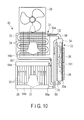
- FIG. 10 schematically illustrates a natural circulation type cooling apparatus according to a fourth embodiment.
- the condenser 24 and radiator 26 are disposed on the rear side of the heat receiver 22, and the condenser 24 is disposed at the upper part and the radiator 26 is disposed at the lower part.
- the condenser 24 and radiator 26 are provided on a plane which is perpendicular to the heat receiver 22.
- the air blower 28 is disposed to be opposed to the condenser 24 and radiator 26 on the rear side of the heat receiver 22, so that cooling air may flow through both the condenser 24 and radiator 26.
- a plurality of cooling apparatuses 10 may be arranged in parallel, so that each individual condenser 24 and radiator 26 may be air-cooled as one body by one air blower 28, and the plural individual condensers 24 and radiators 26 may be air-cooled batchwise at the same time.
- the condenser 24 and radiator 26 are air-cooled as one body, and the cooling air 31 by the air blower 28 flows through the condenser 24 and radiator 26, and flows in a plane direction which is parallel to the rear surface of the heat receiver 22 and to the heat receiving surface 30a to which the semiconductor devices 36 are attached.
- the cooling air 31 flows through each condenser 24 and radiator 26.
- the same advantageous effects as with the above-described third embodiment can be obtained, and the cooling air 31 can be flown to the heat receiver 22 from the lateral surface side.
- many similar cooling apparatuses can easily be arranged in parallel on this lateral surface side.
- the same advantageous effects as with the first embodiment can be obtained.
- FIG. 11 schematically illustrates a natural circulation type cooling apparatus according to a fifth embodiment.
- a cooling apparatus 10 according to the fifth embodiment includes two heat receivers 22 which are disposed to be opposed to each other, and a condenser 24 and a radiator 26 which are provided between the heat receivers 22, that is, on the rear sides of both heat receivers 22.
- the condenser 24 and radiator 26 are provided on a plane which is perpendicular to the heat receivers 22, and the condenser is 24 is disposed at the upper part and the radiator 26 is disposed at the lower part.
- no semiconductor device 36 is mounted on that surface of the heat receiver 22, which is located on the side facing the condenser 24 and radiator 26, that is, on the rear surface of the heat receiver 22.
- Semiconductor devices 36 are mounted on only the heat receiving surface 30a on the opposite side. The same applies to the structure of the other heat receiver 22.
- the air blower 28 is disposed to be opposed to the condenser 24 and radiator 26.
- vapors 102 which are generated from two heat receivers 22, are condensed into liquid in the condenser 24 and the liquid flows down to the inlets of the heat receivers 22.
- the coolant 34 which has become a high-temperature gas/liquid two-phase fluid in the heat receivers 22, is fed out to the inlet of radiator 26 via coolant conduits 68, and is subjected to heat exchange in the radiator.
- the coolant which has transitioned into a subcool state by the lowering in temperature, flows back to both heat receivers 22.
- the air blower 28 is disposed and heat exchange with outside air is performed by forced air-cooling.
- the air blower 28 is disposed on the lateral side and caused to blow air, and exhaust air is let to escape to the outside of the lateral parts of the apparatuses.
- the condenser 24 and radiator 26 are disposed on the rear sides of the two heat receivers 22, that is, the condenser 24 and radiator 26 are interposed between the two heat receivers 22.
- the apparatus size in the horizontal direction can be reduced.
- many apparatuses may be disposed in parallel in the horizontal direction or vertical direction, and the degree of freedom of design can be enhanced, relative to the increase in number of semiconductor devices.
- the air blower 28 by disposing the air blower 28 on the lateral surface side or bottom surface side of the condenser 24 and radiator 26, the degree of freedom of disposition of the external air blower can also be enhanced.
- the condenser 24 and radiator 26 can be cooled, but also air can be blown to the heat receivers 22.
- the temperature level in the cooling apparatus can be lowered, and the tolerable temperature of semiconductor devices can further be lowered.
- the heat-removal limit value can also be increased.
- the same advantageous effects as with the first embodiment can be obtained.
- FIG. 12 schematically illustrates a natural circulation type cooling apparatus according to a sixth embodiment.
- a cooling apparatus 10 according to the sixth embodiment includes a heat receiver 22, a condenser 24 and a radiator 26, which are provided on the same plane. These components are disposed closer to each other and are constructed as a unit.
- the other structure of the cooling apparatus and the structure of each structural element are identical to those in the above-described first embodiment.
- the same advantageous effects as with the above-described first embodiment can be obtained, and the size and weight of the apparatus can be reduced by constructing the apparatus as a single unit.
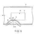
- FIG. 13 schematically illustrates a railway vehicle in which a natural circulation type cooling apparatus according to a seventh embodiment is mounted.
- a heat receiver 22 of a cooling apparatus 10 is disposed within a housing 21 of a power converter 20 which is provided under the floor of the vehicle body 16, and a plurality of semiconductor devices, which are exothermic bodies, are mounted on the heat receiving surface of the heat receiver 22.
- a condenser 24 and a radiator 26 of the cooling apparatus 10 are disposed on a horizontally lateral side of the heat receiver 22, on the outside of the housing 21.
- the vehicle body 16 includes an air duct 80 for guiding a traveling wind caused by traveling, and the condenser 24 and radiator 26 are disposed in the air duct 80. Thereby, the condenser 24 and radiator 26 are cooled as one body by the traveling wind flowing in the air duct 80. In this case, the air blower 28 may be dispensed with.
- the other structure of the cooling apparatus 10 is identical to that of the above-described first embodiment. According to the cooling apparatus having this structure, the same advantageous effects as with the first embodiment can be obtained. Moreover, the air blower can be dispensed with, and the manufacturing cost and the space for installation can be reduced.
- the exothermic body which is a target of cooling of the cooling apparatus, is not limited to a semiconductor device of a power converter, and may be other exothermic bodies.
- the material, of which the heat receiver and heat receiving surface are formed, is not limited to the examples in the above-described embodiment, and may be selected from various materials.
Landscapes
- Engineering & Computer Science (AREA)
- Microelectronics & Electronic Packaging (AREA)
- Physics & Mathematics (AREA)
- Thermal Sciences (AREA)
- Life Sciences & Earth Sciences (AREA)
- Sustainable Development (AREA)
- Mechanical Engineering (AREA)
- General Engineering & Computer Science (AREA)
- Cooling Or The Like Of Semiconductors Or Solid State Devices (AREA)
- Cooling Or The Like Of Electrical Apparatus (AREA)
- Heat-Exchange Devices With Radiators And Conduit Assemblies (AREA)
Applications Claiming Priority (1)
| Application Number | Priority Date | Filing Date | Title |
|---|---|---|---|
| JP2012117812A JP2013247148A (ja) | 2012-05-23 | 2012-05-23 | 自然循環型冷却装置 |
Publications (3)
| Publication Number | Publication Date |
|---|---|
| EP2667408A2 true EP2667408A2 (de) | 2013-11-27 |
| EP2667408A3 EP2667408A3 (de) | 2014-12-31 |
| EP2667408B1 EP2667408B1 (de) | 2019-04-10 |
Family
ID=46851836
Family Applications (1)
| Application Number | Title | Priority Date | Filing Date |
|---|---|---|---|
| EP12183408.9A Not-in-force EP2667408B1 (de) | 2012-05-23 | 2012-09-07 | Kühlvorrichtung mit natürlicher zirkulation |
Country Status (4)
| Country | Link |
|---|---|
| US (1) | US20130312937A1 (de) |
| EP (1) | EP2667408B1 (de) |
| JP (1) | JP2013247148A (de) |
| CN (1) | CN103424019B (de) |
Cited By (2)
| Publication number | Priority date | Publication date | Assignee | Title |
|---|---|---|---|---|
| US20220232734A1 (en) * | 2021-01-15 | 2022-07-21 | Microsoft Technology Licensing, Llc | Systems and methods for immersion cooling with an air-cooled condenser |
| WO2023235244A1 (en) * | 2022-05-31 | 2023-12-07 | GE Grid GmbH | Hybrid thermosyphon with immersion cooled evaporator |
Families Citing this family (15)
| Publication number | Priority date | Publication date | Assignee | Title |
|---|---|---|---|---|
| US9863302B2 (en) * | 2011-12-09 | 2018-01-09 | Mitsubishi Electric Corporation | Cooling device for under-floor device for vehicle |
| TWI494051B (zh) * | 2012-11-19 | 2015-07-21 | 宏碁股份有限公司 | 流體熱交換裝置 |
| US10364043B2 (en) * | 2014-07-02 | 2019-07-30 | Embraer S.A. | Passive aircraft cooling systems and methods |
| CN105451503B (zh) * | 2014-07-21 | 2019-03-08 | 联想(北京)有限公司 | 一种电子设备 |
| US10638648B2 (en) * | 2016-04-28 | 2020-04-28 | Ge Energy Power Conversion Technology Ltd. | Cooling system with pressure regulation |
| US10124681B2 (en) * | 2016-05-31 | 2018-11-13 | Fuji Electric Co., Ltd. | Railway vehicle power converter |
| US11252847B2 (en) * | 2017-06-30 | 2022-02-15 | General Electric Company | Heat dissipation system and an associated method thereof |
| JP6914776B2 (ja) * | 2017-08-04 | 2021-08-04 | 株式会社東芝 | 電力変換装置及び鉄道車両 |
| KR102393486B1 (ko) * | 2017-09-13 | 2022-05-04 | 한온시스템 주식회사 | 냉각 장치 |
| GB201815626D0 (en) * | 2018-09-25 | 2018-11-07 | Hughes Safety Showers Ltd | Water cooler |
| TWI718485B (zh) * | 2019-02-27 | 2021-02-11 | 雙鴻科技股份有限公司 | 熱交換裝置 |
| JP7250584B2 (ja) * | 2019-03-27 | 2023-04-03 | 日立Astemo株式会社 | 冷却システム |
| CN112584676B (zh) * | 2020-12-01 | 2022-04-15 | 敖立鸿 | 一种半浸没式溶液蒸发散热器 |
| CN112776839B (zh) * | 2021-02-25 | 2022-02-01 | 郑州铁路职业技术学院 | 一种铁路机车的低温除雾装置 |
| US12336152B2 (en) * | 2021-12-15 | 2025-06-17 | Baidu Usa Llc | Hybrid system for servers |
Family Cites Families (15)
| Publication number | Priority date | Publication date | Assignee | Title |
|---|---|---|---|---|
| US4061131A (en) * | 1975-11-24 | 1977-12-06 | Acme Engineering And Manufacturing Corporation | Heat transfer system particularly applicable to solar heating installations |
| US4270521A (en) * | 1979-08-15 | 1981-06-02 | Brekke Carroll Ellerd | Solar heating system |
| JPS61119997A (ja) * | 1984-11-15 | 1986-06-07 | Sumitomo Electric Ind Ltd | ル−プ式ヒ−トパイプ |
| US5257660A (en) * | 1992-06-30 | 1993-11-02 | Aaron J. Cargile | Thermal transport oscillator |
| JP3908369B2 (ja) * | 1997-12-29 | 2007-04-25 | 株式会社フジクラ | 熱駆動型冷却装置 |
| JP3964580B2 (ja) * | 1999-09-03 | 2007-08-22 | 富士通株式会社 | 冷却ユニット |
| US20050115698A1 (en) * | 2003-12-02 | 2005-06-02 | Jung-Yen Hsu | Structure of heat sink |
| EP1702360A2 (de) * | 2003-12-08 | 2006-09-20 | Noise Limit ApS | Kühlsystem mit einer blasenpumpe |
| JP2005268658A (ja) * | 2004-03-19 | 2005-09-29 | Denso Corp | 沸騰冷却装置 |
| RU2007129729A (ru) * | 2005-01-03 | 2009-02-10 | НОЙЗ ЛИМИТ АпС (DK) | Многоориентационная система охлаждения с пузырьковым насосом |
| JP4882699B2 (ja) * | 2005-12-20 | 2012-02-22 | 株式会社デンソー | 排熱回収装置 |
| US8107241B2 (en) * | 2006-03-31 | 2012-01-31 | Mitsubishi Electric Corporation | Electric power conversion apparatus including cooling units |
| MX2008012650A (es) * | 2006-04-13 | 2009-01-16 | Mitsubishi Electric Corp | Aparato de enfriamiento y convertidor de energia. |
| JP4666084B2 (ja) * | 2009-03-13 | 2011-04-06 | 三菱電機株式会社 | 電車用の電力変換装置 |
| JP5210997B2 (ja) * | 2009-08-28 | 2013-06-12 | 株式会社日立製作所 | 冷却システム、及び、それを用いる電子装置 |
-
2012
- 2012-05-23 JP JP2012117812A patent/JP2013247148A/ja active Pending
- 2012-09-07 EP EP12183408.9A patent/EP2667408B1/de not_active Not-in-force
- 2012-09-07 US US13/607,424 patent/US20130312937A1/en not_active Abandoned
- 2012-09-14 CN CN201210342325.9A patent/CN103424019B/zh not_active Expired - Fee Related
Non-Patent Citations (1)
| Title |
|---|
| None |
Cited By (3)
| Publication number | Priority date | Publication date | Assignee | Title |
|---|---|---|---|---|
| US20220232734A1 (en) * | 2021-01-15 | 2022-07-21 | Microsoft Technology Licensing, Llc | Systems and methods for immersion cooling with an air-cooled condenser |
| WO2023235244A1 (en) * | 2022-05-31 | 2023-12-07 | GE Grid GmbH | Hybrid thermosyphon with immersion cooled evaporator |
| US11943904B2 (en) | 2022-05-31 | 2024-03-26 | GE Grid GmbH | Hybrid thermosyphon with immersion cooled evaporator |
Also Published As
| Publication number | Publication date |
|---|---|
| EP2667408A3 (de) | 2014-12-31 |
| JP2013247148A (ja) | 2013-12-09 |
| EP2667408B1 (de) | 2019-04-10 |
| CN103424019B (zh) | 2016-02-17 |
| US20130312937A1 (en) | 2013-11-28 |
| CN103424019A (zh) | 2013-12-04 |
Similar Documents
| Publication | Publication Date | Title |
|---|---|---|
| EP2667408B1 (de) | Kühlvorrichtung mit natürlicher zirkulation | |
| US8879259B2 (en) | Cooling system for onboard electrical power converter, and electrical power converter for railway vehicle | |
| CA2820330C (en) | Two-phase cooling system for electronic components | |
| US6527045B1 (en) | Cooling apparatus boiling and condensing refrigerant | |
| CN104704934B (zh) | 冷却装置以及具备该冷却装置的电力转换装置 | |
| US10828582B2 (en) | Passive air bleed for improved cooling systems | |
| US20160209120A1 (en) | Boiling heat transfer device | |
| MX2008012650A (es) | Aparato de enfriamiento y convertidor de energia. | |
| WO2007116894A1 (ja) | 冷却器 | |
| JP2015055380A (ja) | 冷却装置 | |
| US20130255920A1 (en) | Ebullient cooling device | |
| JP5786132B2 (ja) | 電気自動車 | |
| US20090065182A1 (en) | Cooling device | |
| JP3181289U (ja) | 放熱装置 | |
| JP2014154683A (ja) | 冷却装置 | |
| EP2802832B1 (de) | Wärmetauscher | |
| JP3924674B2 (ja) | 発熱素子用沸騰冷却器 | |
| JP3887857B2 (ja) | 沸騰冷却装置及びそれを用いた筐体冷却装置 | |
| CN114340304A (zh) | 具有冷却系统的电功率模块 | |
| JP2010206098A (ja) | 冷却装置 | |
| CN119342751A (zh) | 散热组件及功率变换设备 | |
| KR101867458B1 (ko) | 차량용 열전발전 시스템 | |
| JP3893651B2 (ja) | 沸騰冷却装置及びそれを用いた筐体冷却装置 | |
| JP2014048002A (ja) | 冷却装置およびこれを搭載した電気自動車および電子機器 | |
| JP2017112189A (ja) | サーモサイフォン冷却装置 |
Legal Events
| Date | Code | Title | Description |
|---|---|---|---|
| PUAI | Public reference made under article 153(3) epc to a published international application that has entered the european phase |
Free format text: ORIGINAL CODE: 0009012 |
|
| 17P | Request for examination filed |
Effective date: 20120907 |
|
| AK | Designated contracting states |
Kind code of ref document: A2 Designated state(s): AL AT BE BG CH CY CZ DE DK EE ES FI FR GB GR HR HU IE IS IT LI LT LU LV MC MK MT NL NO PL PT RO RS SE SI SK SM TR |
|
| AX | Request for extension of the european patent |
Extension state: BA ME |
|
| PUAL | Search report despatched |
Free format text: ORIGINAL CODE: 0009013 |
|
| AK | Designated contracting states |
Kind code of ref document: A3 Designated state(s): AL AT BE BG CH CY CZ DE DK EE ES FI FR GB GR HR HU IE IS IT LI LT LU LV MC MK MT NL NO PL PT RO RS SE SI SK SM TR |
|
| AX | Request for extension of the european patent |
Extension state: BA ME |
|
| RIC1 | Information provided on ipc code assigned before grant |
Ipc: F28D 15/02 20060101ALN20141127BHEP Ipc: H01L 23/427 20060101AFI20141127BHEP Ipc: H05K 7/20 20060101ALI20141127BHEP |
|
| GRAP | Despatch of communication of intention to grant a patent |
Free format text: ORIGINAL CODE: EPIDOSNIGR1 |
|
| STAA | Information on the status of an ep patent application or granted ep patent |
Free format text: STATUS: GRANT OF PATENT IS INTENDED |
|
| INTG | Intention to grant announced |
Effective date: 20181029 |
|
| GRAS | Grant fee paid |
Free format text: ORIGINAL CODE: EPIDOSNIGR3 |
|
| GRAA | (expected) grant |
Free format text: ORIGINAL CODE: 0009210 |
|
| STAA | Information on the status of an ep patent application or granted ep patent |
Free format text: STATUS: THE PATENT HAS BEEN GRANTED |
|
| AK | Designated contracting states |
Kind code of ref document: B1 Designated state(s): AL AT BE BG CH CY CZ DE DK EE ES FI FR GB GR HR HU IE IS IT LI LT LU LV MC MK MT NL NO PL PT RO RS SE SI SK SM TR |
|
| REG | Reference to a national code |
Ref country code: GB Ref legal event code: FG4D |
|
| REG | Reference to a national code |
Ref country code: CH Ref legal event code: EP Ref country code: AT Ref legal event code: REF Ref document number: 1119834 Country of ref document: AT Kind code of ref document: T Effective date: 20190415 |
|
| REG | Reference to a national code |
Ref country code: DE Ref legal event code: R096 Ref document number: 602012058762 Country of ref document: DE |
|
| REG | Reference to a national code |
Ref country code: IE Ref legal event code: FG4D |
|
| REG | Reference to a national code |
Ref country code: NL Ref legal event code: MP Effective date: 20190410 |
|
| REG | Reference to a national code |
Ref country code: LT Ref legal event code: MG4D |
|
| REG | Reference to a national code |
Ref country code: AT Ref legal event code: MK05 Ref document number: 1119834 Country of ref document: AT Kind code of ref document: T Effective date: 20190410 |
|
| PG25 | Lapsed in a contracting state [announced via postgrant information from national office to epo] |
Ref country code: NL Free format text: LAPSE BECAUSE OF FAILURE TO SUBMIT A TRANSLATION OF THE DESCRIPTION OR TO PAY THE FEE WITHIN THE PRESCRIBED TIME-LIMIT Effective date: 20190410 |
|
| PG25 | Lapsed in a contracting state [announced via postgrant information from national office to epo] |
Ref country code: AL Free format text: LAPSE BECAUSE OF FAILURE TO SUBMIT A TRANSLATION OF THE DESCRIPTION OR TO PAY THE FEE WITHIN THE PRESCRIBED TIME-LIMIT Effective date: 20190410 Ref country code: FI Free format text: LAPSE BECAUSE OF FAILURE TO SUBMIT A TRANSLATION OF THE DESCRIPTION OR TO PAY THE FEE WITHIN THE PRESCRIBED TIME-LIMIT Effective date: 20190410 Ref country code: LT Free format text: LAPSE BECAUSE OF FAILURE TO SUBMIT A TRANSLATION OF THE DESCRIPTION OR TO PAY THE FEE WITHIN THE PRESCRIBED TIME-LIMIT Effective date: 20190410 Ref country code: PT Free format text: LAPSE BECAUSE OF FAILURE TO SUBMIT A TRANSLATION OF THE DESCRIPTION OR TO PAY THE FEE WITHIN THE PRESCRIBED TIME-LIMIT Effective date: 20190910 Ref country code: HR Free format text: LAPSE BECAUSE OF FAILURE TO SUBMIT A TRANSLATION OF THE DESCRIPTION OR TO PAY THE FEE WITHIN THE PRESCRIBED TIME-LIMIT Effective date: 20190410 Ref country code: SE Free format text: LAPSE BECAUSE OF FAILURE TO SUBMIT A TRANSLATION OF THE DESCRIPTION OR TO PAY THE FEE WITHIN THE PRESCRIBED TIME-LIMIT Effective date: 20190410 Ref country code: NO Free format text: LAPSE BECAUSE OF FAILURE TO SUBMIT A TRANSLATION OF THE DESCRIPTION OR TO PAY THE FEE WITHIN THE PRESCRIBED TIME-LIMIT Effective date: 20190710 Ref country code: ES Free format text: LAPSE BECAUSE OF FAILURE TO SUBMIT A TRANSLATION OF THE DESCRIPTION OR TO PAY THE FEE WITHIN THE PRESCRIBED TIME-LIMIT Effective date: 20190410 |
|
| PG25 | Lapsed in a contracting state [announced via postgrant information from national office to epo] |
Ref country code: LV Free format text: LAPSE BECAUSE OF FAILURE TO SUBMIT A TRANSLATION OF THE DESCRIPTION OR TO PAY THE FEE WITHIN THE PRESCRIBED TIME-LIMIT Effective date: 20190410 Ref country code: PL Free format text: LAPSE BECAUSE OF FAILURE TO SUBMIT A TRANSLATION OF THE DESCRIPTION OR TO PAY THE FEE WITHIN THE PRESCRIBED TIME-LIMIT Effective date: 20190410 Ref country code: BG Free format text: LAPSE BECAUSE OF FAILURE TO SUBMIT A TRANSLATION OF THE DESCRIPTION OR TO PAY THE FEE WITHIN THE PRESCRIBED TIME-LIMIT Effective date: 20190710 Ref country code: GR Free format text: LAPSE BECAUSE OF FAILURE TO SUBMIT A TRANSLATION OF THE DESCRIPTION OR TO PAY THE FEE WITHIN THE PRESCRIBED TIME-LIMIT Effective date: 20190711 Ref country code: RS Free format text: LAPSE BECAUSE OF FAILURE TO SUBMIT A TRANSLATION OF THE DESCRIPTION OR TO PAY THE FEE WITHIN THE PRESCRIBED TIME-LIMIT Effective date: 20190410 |
|
| PG25 | Lapsed in a contracting state [announced via postgrant information from national office to epo] |
Ref country code: IS Free format text: LAPSE BECAUSE OF FAILURE TO SUBMIT A TRANSLATION OF THE DESCRIPTION OR TO PAY THE FEE WITHIN THE PRESCRIBED TIME-LIMIT Effective date: 20190810 Ref country code: AT Free format text: LAPSE BECAUSE OF FAILURE TO SUBMIT A TRANSLATION OF THE DESCRIPTION OR TO PAY THE FEE WITHIN THE PRESCRIBED TIME-LIMIT Effective date: 20190410 |
|
| REG | Reference to a national code |
Ref country code: DE Ref legal event code: R097 Ref document number: 602012058762 Country of ref document: DE |
|
| PG25 | Lapsed in a contracting state [announced via postgrant information from national office to epo] |
Ref country code: RO Free format text: LAPSE BECAUSE OF FAILURE TO SUBMIT A TRANSLATION OF THE DESCRIPTION OR TO PAY THE FEE WITHIN THE PRESCRIBED TIME-LIMIT Effective date: 20190410 Ref country code: CZ Free format text: LAPSE BECAUSE OF FAILURE TO SUBMIT A TRANSLATION OF THE DESCRIPTION OR TO PAY THE FEE WITHIN THE PRESCRIBED TIME-LIMIT Effective date: 20190410 Ref country code: EE Free format text: LAPSE BECAUSE OF FAILURE TO SUBMIT A TRANSLATION OF THE DESCRIPTION OR TO PAY THE FEE WITHIN THE PRESCRIBED TIME-LIMIT Effective date: 20190410 Ref country code: DK Free format text: LAPSE BECAUSE OF FAILURE TO SUBMIT A TRANSLATION OF THE DESCRIPTION OR TO PAY THE FEE WITHIN THE PRESCRIBED TIME-LIMIT Effective date: 20190410 Ref country code: SK Free format text: LAPSE BECAUSE OF FAILURE TO SUBMIT A TRANSLATION OF THE DESCRIPTION OR TO PAY THE FEE WITHIN THE PRESCRIBED TIME-LIMIT Effective date: 20190410 |
|
| PLBE | No opposition filed within time limit |
Free format text: ORIGINAL CODE: 0009261 |
|
| STAA | Information on the status of an ep patent application or granted ep patent |
Free format text: STATUS: NO OPPOSITION FILED WITHIN TIME LIMIT |
|
| PG25 | Lapsed in a contracting state [announced via postgrant information from national office to epo] |
Ref country code: SM Free format text: LAPSE BECAUSE OF FAILURE TO SUBMIT A TRANSLATION OF THE DESCRIPTION OR TO PAY THE FEE WITHIN THE PRESCRIBED TIME-LIMIT Effective date: 20190410 Ref country code: IT Free format text: LAPSE BECAUSE OF FAILURE TO SUBMIT A TRANSLATION OF THE DESCRIPTION OR TO PAY THE FEE WITHIN THE PRESCRIBED TIME-LIMIT Effective date: 20190410 |
|
| 26N | No opposition filed |
Effective date: 20200113 |
|
| PG25 | Lapsed in a contracting state [announced via postgrant information from national office to epo] |
Ref country code: TR Free format text: LAPSE BECAUSE OF FAILURE TO SUBMIT A TRANSLATION OF THE DESCRIPTION OR TO PAY THE FEE WITHIN THE PRESCRIBED TIME-LIMIT Effective date: 20190410 |
|
| PG25 | Lapsed in a contracting state [announced via postgrant information from national office to epo] |
Ref country code: SI Free format text: LAPSE BECAUSE OF FAILURE TO SUBMIT A TRANSLATION OF THE DESCRIPTION OR TO PAY THE FEE WITHIN THE PRESCRIBED TIME-LIMIT Effective date: 20190410 Ref country code: MC Free format text: LAPSE BECAUSE OF FAILURE TO SUBMIT A TRANSLATION OF THE DESCRIPTION OR TO PAY THE FEE WITHIN THE PRESCRIBED TIME-LIMIT Effective date: 20190410 |
|
| REG | Reference to a national code |
Ref country code: CH Ref legal event code: PL |
|
| PG25 | Lapsed in a contracting state [announced via postgrant information from national office to epo] |
Ref country code: LU Free format text: LAPSE BECAUSE OF NON-PAYMENT OF DUE FEES Effective date: 20190907 Ref country code: IE Free format text: LAPSE BECAUSE OF NON-PAYMENT OF DUE FEES Effective date: 20190907 Ref country code: CH Free format text: LAPSE BECAUSE OF NON-PAYMENT OF DUE FEES Effective date: 20190930 Ref country code: LI Free format text: LAPSE BECAUSE OF NON-PAYMENT OF DUE FEES Effective date: 20190930 |
|
| REG | Reference to a national code |
Ref country code: BE Ref legal event code: MM Effective date: 20190930 |
|
| PG25 | Lapsed in a contracting state [announced via postgrant information from national office to epo] |
Ref country code: BE Free format text: LAPSE BECAUSE OF NON-PAYMENT OF DUE FEES Effective date: 20190930 |
|
| GBPC | Gb: european patent ceased through non-payment of renewal fee |
Effective date: 20190907 |
|
| PG25 | Lapsed in a contracting state [announced via postgrant information from national office to epo] |
Ref country code: GB Free format text: LAPSE BECAUSE OF NON-PAYMENT OF DUE FEES Effective date: 20190907 |
|
| PG25 | Lapsed in a contracting state [announced via postgrant information from national office to epo] |
Ref country code: CY Free format text: LAPSE BECAUSE OF FAILURE TO SUBMIT A TRANSLATION OF THE DESCRIPTION OR TO PAY THE FEE WITHIN THE PRESCRIBED TIME-LIMIT Effective date: 20190410 |
|
| PG25 | Lapsed in a contracting state [announced via postgrant information from national office to epo] |
Ref country code: HU Free format text: LAPSE BECAUSE OF FAILURE TO SUBMIT A TRANSLATION OF THE DESCRIPTION OR TO PAY THE FEE WITHIN THE PRESCRIBED TIME-LIMIT; INVALID AB INITIO Effective date: 20120907 Ref country code: MT Free format text: LAPSE BECAUSE OF FAILURE TO SUBMIT A TRANSLATION OF THE DESCRIPTION OR TO PAY THE FEE WITHIN THE PRESCRIBED TIME-LIMIT Effective date: 20190410 |
|
| PGFP | Annual fee paid to national office [announced via postgrant information from national office to epo] |
Ref country code: FR Payment date: 20210812 Year of fee payment: 10 |
|
| PGFP | Annual fee paid to national office [announced via postgrant information from national office to epo] |
Ref country code: DE Payment date: 20210727 Year of fee payment: 10 |
|
| PG25 | Lapsed in a contracting state [announced via postgrant information from national office to epo] |
Ref country code: MK Free format text: LAPSE BECAUSE OF FAILURE TO SUBMIT A TRANSLATION OF THE DESCRIPTION OR TO PAY THE FEE WITHIN THE PRESCRIBED TIME-LIMIT Effective date: 20190410 |
|
| REG | Reference to a national code |
Ref country code: DE Ref legal event code: R119 Ref document number: 602012058762 Country of ref document: DE |
|
| PG25 | Lapsed in a contracting state [announced via postgrant information from national office to epo] |
Ref country code: FR Free format text: LAPSE BECAUSE OF NON-PAYMENT OF DUE FEES Effective date: 20220930 Ref country code: DE Free format text: LAPSE BECAUSE OF NON-PAYMENT OF DUE FEES Effective date: 20230401 |