EP2802832B1 - Wärmetauscher - Google Patents
Wärmetauscher Download PDFInfo
- Publication number
- EP2802832B1 EP2802832B1 EP12822981.2A EP12822981A EP2802832B1 EP 2802832 B1 EP2802832 B1 EP 2802832B1 EP 12822981 A EP12822981 A EP 12822981A EP 2802832 B1 EP2802832 B1 EP 2802832B1
- Authority
- EP
- European Patent Office
- Prior art keywords
- chamber
- panel
- fluid
- heat
- duct
- Prior art date
- Legal status (The legal status is an assumption and is not a legal conclusion. Google has not performed a legal analysis and makes no representation as to the accuracy of the status listed.)
- Active
Links
Images

Classifications
-
- F—MECHANICAL ENGINEERING; LIGHTING; HEATING; WEAPONS; BLASTING
- F28—HEAT EXCHANGE IN GENERAL
- F28D—HEAT-EXCHANGE APPARATUS, NOT PROVIDED FOR IN ANOTHER SUBCLASS, IN WHICH THE HEAT-EXCHANGE MEDIA DO NOT COME INTO DIRECT CONTACT
- F28D15/00—Heat-exchange apparatus with the intermediate heat-transfer medium in closed tubes passing into or through the conduit walls ; Heat-exchange apparatus employing intermediate heat-transfer medium or bodies
- F28D15/02—Heat-exchange apparatus with the intermediate heat-transfer medium in closed tubes passing into or through the conduit walls ; Heat-exchange apparatus employing intermediate heat-transfer medium or bodies in which the medium condenses and evaporates, e.g. heat pipes
- F28D15/0266—Heat-exchange apparatus with the intermediate heat-transfer medium in closed tubes passing into or through the conduit walls ; Heat-exchange apparatus employing intermediate heat-transfer medium or bodies in which the medium condenses and evaporates, e.g. heat pipes with separate evaporating and condensing chambers connected by at least one conduit; Loop-type heat pipes; with multiple or common evaporating or condensing chambers
-
- F—MECHANICAL ENGINEERING; LIGHTING; HEATING; WEAPONS; BLASTING
- F28—HEAT EXCHANGE IN GENERAL
- F28D—HEAT-EXCHANGE APPARATUS, NOT PROVIDED FOR IN ANOTHER SUBCLASS, IN WHICH THE HEAT-EXCHANGE MEDIA DO NOT COME INTO DIRECT CONTACT
- F28D15/00—Heat-exchange apparatus with the intermediate heat-transfer medium in closed tubes passing into or through the conduit walls ; Heat-exchange apparatus employing intermediate heat-transfer medium or bodies
- F28D15/02—Heat-exchange apparatus with the intermediate heat-transfer medium in closed tubes passing into or through the conduit walls ; Heat-exchange apparatus employing intermediate heat-transfer medium or bodies in which the medium condenses and evaporates, e.g. heat pipes
- F28D15/025—Heat-exchange apparatus with the intermediate heat-transfer medium in closed tubes passing into or through the conduit walls ; Heat-exchange apparatus employing intermediate heat-transfer medium or bodies in which the medium condenses and evaporates, e.g. heat pipes having non-capillary condensate return means
Definitions
- the present invention relates to a heat exchanger and particularly, but not exclusively to a heat exchanger for exchanging heat with a medium, across a substantially planar surface.
- a heat pipe is a hermetically sealed, evacuated tube comprising a working fluid in both the liquid and vapour phase.
- the liquid turns to vapour upon absorbing the latent heat of vaporization.
- the hot vapour subsequently passes to the cooler end of the tube where it condenses and gives out the latent heat to the tube.
- the condensed liquid then flows back to the hot end of the tube and the vaporization-condensation cycle repeats. Since the latent heat of vaporization is usually very large, considerable quantities of heat can be transferred along the tube and a substantially uniform temperature distribution can be achieved along the heat pipe.
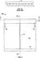
- the exchanger 10 comprises a plurality of heat pipes 11 which are coupled along a proximal portion 11a thereof to a rear face of a panel 12.
- the heat pipes 11 are arranged in a substantially parallel configuration and extend along the length of the panel 12.
- the panel 12 is arranged to absorb heat from the planar surface (not shown) and the heat absorbed is communicated to the proximal portion 11a of the heat pipes 11 which causes the fluid (not shown) disposed therein to turn to a vapour.
- the distal portion 11b of the pipes 11 are arranged to extend within a flow duct 13 along which a cooling fluid (not shown) is arranged to pass, so that the vapour which passes to the distal portion 11b of the pipes 11 can condense.
- the condensate, namely the cooled working fluid can subsequently return to the proximal portion 11a of the heat pipes 11 for further absorption of heat from the panel 12.
- the cooling fluid (not shown) is arranged to extract the heat absorbed by the working fluid so that the heat pipes 11, and in particular, the fluid disposed within the heat pipes 11 can continue to absorb heat.
- a problem with this arrangement is that the temperature of the working fluid within the heat pipes 11 rises during use, which reduces the ability of the fluid to absorb further heat from the panel 12. Furthermore, it is often difficult to separately seal the distal portion 11b of each heat pipe 11 to the flow duct 13, with the result that the cooling fluid can leak out of the duct.
- DE9101673U discloses a heat exchanger according to the preamble of claim 1.
- a heat exchanger for absorbing heat from a medium across a substantially planar surface comprising:
- circuit provides for a separate return path, namely the duct, for the fluid so that thermal state of the fluid can recover for further heat exchange with the panel.
- a separate return path namely the duct
- the fluid so that thermal state of the fluid can recover for further heat exchange with the panel.
- the panel absorbs heat
- the heat is transferred to the fluid within the passages.
- the absorbed heat is arranged to cause the fluid to evaporate and this evaporate is arranged to pass to the second chamber where it can condense.
- the condensed, i.e. cooled, fluid can then return to the first chamber along the duct for subsequent heat exchange with the panel.
- the panel is preferably arranged to exchange heat with the fluid disposed within the passages and the passages are preferably arranged to extend within the panel.
- the disposition of the passages within the panel provides for an intimate contact of the side walls of the passage and thus the fluid with the panel and maximises the surface area of the passage which is in contact with the panel. It is also found that the formation of the passages within the panel facilitates an improved sealing of the chambers to the passages, compared with the prior art, since the chambers are only required to form a single seal and with a planar surface, namely the panel, as opposed to a number of separate seals to each passage.
- the duct is arranged to extend between the first and second chambers in spaced relation to the panel. This minimises the exposure of the duct to the thermal state, for example the heated state, of the panel.
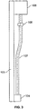
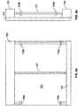
- the exchanger 100 for facilitating the exchange of heat with a planar surface (not shown), such as a wall of a heated body, a casing of a refrigeration unit, circuit boards and the like.
- the exchanger 100 comprises a substantially planar, heat exchanging panel 101 which is arranged to form a thermal contact along a front surface 101a thereof with the surface with which heat exchange is desirable.
- the planar form of the panel 101 is arranged to conform with the planar surface (not shown) to maximise the contact area with the planar surface and thus the exchange of heat therewith.
- the exchanger 100 further comprises a fluid transfer circuit for circulating a fluid 102 disposed therein, around the exchanger 100.
- the circuit comprises a plurality of passages 103 which are arranged to extend along the panel 101 in a direction which is within the plane of the panel 101.
- the passages 103 may be formed integrally with the panel 101 by casting in a mould for example.
- the passages 103 may extend along a rear surface 101b of the panel 101, in thermal contact therewith, although the skilled reader will recognise that this may reduce the thermal exchange with the fluid 102, compared with passages 103 which extend within the panel 101.
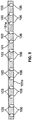
- the circuit further comprises a first and second chamber 104, 105, disposed at a first and second end of the panel 101, respectively.
- the passages 103 are arranged to extend in a substantially parallel orientation, between the first end of the panel 101 and the second end of the panel 101, which is substantially opposite the first end.
- Each passage 103 is coupled to the first and second chamber 104, 105 by a respective transfer duct 106 which is orientated substantially perpendicular to the respective passage 103 and which is arranged to extend rearwardly of the panel 101 toward the respective chamber 104, 105.
- the first and second chambers 104, 105 are disposed upon the rear face 101b of the panel 101 and extend along the panel 101 in a direction which is substantially perpendicular to the passages 103.
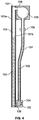
- the circuit further comprises a duct 107, which extends between the first and second chambers 104, 105, substantially perpendicular thereto and in spaced relation to the panel 101.
- the heat exchanger 100 is orientated so that the first chamber 104 is arranged at a vertical height which is below the second chamber 105 and the duct 107 is arranged to extend from an underside of the second chamber 105 to an upper region of the first chamber 104.
- the second chamber 105 comprises a substantially circular cross-sectional shape so that any fluid 102 which passes to the second chamber 105 can settle at a lower region thereof, proximate the duct 107, and pass under gravity back to the first chamber 104.
- the front surface 101a of the panel 101 is first disposed in thermal contact with the receptacle (not shown). This contact may be enhanced using a thermal paste (not shown) as an interface medium between the panel 101 and the receptacle (not shown), for example.
- the panel 101 is orientated with the first chamber 104 disposed at a vertical height below the second chamber 105 and in an idle state in which no heat exchange takes place, the fluid 102 within the circuit is arranged to fill the first chamber 104 and extend partly along the passages 103 and the duct 107.
- the first chamber 104 serves as a reservoir for the fluid 102.
- the panel 101 absorbs heat from the receptacle (not shown), which may be via conduction, convection, radiation or a combination thereof, the heat will become conducted to the passages 103 and thus the fluid 102 within the passages 103.
- the fluid 102 in the passages 103 Upon absorbing the heat from the panel 101, the fluid 102 in the passages 103 is arranged to turn to a vapour and the vapour subsequently passes along the passages 103 to the second chamber 105 disposed at the rear 101b of the panel 100, via the respective transfer ducts 106, where it cools and condenses.
- the condensate subsequently collects in the chamber 105 and passes to the bottom of the chamber 105 into the duct 107 and becomes returned to the first chamber 104.
- the spaced relation of the duct 107 from the panel 101 substantially insulates the duct 107 and the fluid 102 therein from the heat associated with the panel 101, so that the fluid 102 within the duct 107 can recover to its original thermal state for subsequent absorption of heat from the panel 101.
- the second chamber 105 comprises a cooler (not shown) which is arranged to cool the fluid 102 within the circuit and in particular the condensate in the second chamber 105.
- the cooler comprises a cooling duct (not shown) which extends along the second chamber 105 and which comprises an inlet 108 disposed at one end of the chamber 105 and an outlet 109 disposed at an opposite end of the chamber 105.
- the cooling duct (not shown) is arranged to communicate a cooling fluid (not shown) between the inlet 108 and the outlet 109 thereof, within the chamber 105, so that the cooling fluid (not shown) can absorb heat associated with the fluid 102 within the chamber 105 and thus cool the fluid 102 within the chamber 105.
- the first and second chamber 104, 105 separately comprise a cooler (not shown) which are separately arranged to cool the fluid 102 within the first and second chambers 104, 105.
- the coolers (not shown) separately comprise a cooling duct (not shown) which are arranged to communicate a cooling fluid (not shown) between an inlet 108a, 108b and an outlet 109a, 109b thereof, within the respective chamber 104, 105, so that the cooling fluid (not shown) can absorb heat associated with the fluid 102 within the respective chamber 104, 105 and thus cool the fluid 102.
- the outlet 109a of the cooling duct within the first chamber 104 is coupled to the inlet 108b of the cooling duct (not shown) within the second chamber 105 via a conduit 110, so that the cooling fluid 102 can circulate from the cooler (not shown) disposed within the first chamber 104 to the cooler (not shown) disposed within the second chamber 105.
- the coolers are arranged to cool the fluid 102 within the fluid transfer circuit to reduce the working temperature of the fluid 102 and thus increase the capacity of the fluid to absorb heat from the panel 101. This therefore provides for an improved heat exchange with the receptacle (not shown), for example.
- the heat exchanger provides for an improved heat exchanger with a planar surface.
Landscapes
- Engineering & Computer Science (AREA)
- Life Sciences & Earth Sciences (AREA)
- Sustainable Development (AREA)
- Physics & Mathematics (AREA)
- Thermal Sciences (AREA)
- Mechanical Engineering (AREA)
- General Engineering & Computer Science (AREA)
- Heat-Exchange Devices With Radiators And Conduit Assemblies (AREA)
Claims (3)
- Wärmetauscher (100) zum Absorbieren von Wärme aus einem Medium über eine im Wesentlichen ebene Oberfläche, wobei der Wärmetauscher (100) umfasst:eine Wärmetauschplatte (101);einen Fluidkreislauf, der eine erste Kammer (104) umfasst, die an einem ersten Ende der Platte (101) angeordnet ist, eine zweite Kammer (105), die an einem zweiten Ende der Platte (101) angeordnet ist, eine Vielzahl von Durchgängen (103), die sich entlang der Platte (101) zwischen der ersten und zweiten Kammer (104, 105) erstrecken, und einen Kanal (107), der sich zwischen der ersten und der zweiten Kammer (104, 105) erstreckt;ein Fluid (102), das innerhalb des Kreislaufs angeordnet ist; wobei die Vielzahl von Durchgängen (103) in thermischer Verbindung mit der Platte (101) und so angeordnet ist, dass sie das Fluid von der ersten Kammer (104) zur zweiten Kammer (105) durchleitet, und der Kanal (107) so angeordnet ist, dass er das Fluid (102) von der zweiten Kammer (105) zur ersten Kammer (104) durchleitet, und wobei die Platte (101) eine Wärmetauscherfläche (101a) umfasst, die so angeordnet ist, dass sie sich angrenzend an das Medium erstreckt, wobei die erste Kammer (104) so angeordnet ist, dass sie sich in einer vertikalen Höhe erstreckt, die unterhalb der zweiten Kammer (105) liegt, so dass das Fluid (102) unter dem Einfluss der Schwerkraft von der zweiten Kammer (105) zur ersten Kammer (104) entlang des Kanals (107) durchfließen kann, und wobei die zweite Kammer (105) einen Kühler zum Kühlen des innerhalb der Kammer angeordneten Fluids umfasst, wobei der Kühler einen Kühlkanal umfasst, der so angeordnet ist, dass er sich innerhalb der Kammer erstreckt, um ein Kühlfluid zwischen einem Einlass (108b) und einem Auslass (109b) des Kühlkanals durchzuleiten, dadurch gekennzeichnet, dass die erste und zweite Kammer (104, 105) so angeordnet sind, dass sie sich von der Platte (101) weg von der der Wärmetauscherfläche gegenüberliegenden Seite erstrecken, und dass auch die erste Kammer (104) einen Kühler zum Kühlen des in der Kammer angeordneten Fluids umfasst, wobei der Kühler einen Kühlkanal umfasst, der so angeordnet ist, dass er sich innerhalb der Kammer erstreckt, um ein Kühlfluid zwischen einem Einlass (108a) und einem Auslass (109a) des Kühlkanals durchzuleiten, und wobei der Auslass (109a) des einen Kühlkanals mit dem Einlass (108b) des anderen Kühlkanals gekoppelt ist.
- Wärmetauscher nach Anspruch 1, wobei die Durchgänge (103) so angeordnet sind, dass sie sich innerhalb der Platte (101) erstrecken.
- Wärmetauscher nach einem vorhergehenden Anspruch, wobei der Kanal (107) so angeordnet ist, dass er sich zwischen der ersten und zweiten Kammer (104, 105) in beabstandeter Beziehung zu der Platte (101) erstreckt.
Applications Claiming Priority (2)
| Application Number | Priority Date | Filing Date | Title |
|---|---|---|---|
| GB1200480.0A GB2498373B (en) | 2012-01-12 | 2012-01-12 | Heat exchanger |
| PCT/GB2012/053199 WO2013104884A1 (en) | 2012-01-12 | 2012-12-20 | Heat exchanger |
Publications (2)
| Publication Number | Publication Date |
|---|---|
| EP2802832A1 EP2802832A1 (de) | 2014-11-19 |
| EP2802832B1 true EP2802832B1 (de) | 2019-05-08 |
Family
ID=45788821
Family Applications (1)
| Application Number | Title | Priority Date | Filing Date |
|---|---|---|---|
| EP12822981.2A Active EP2802832B1 (de) | 2012-01-12 | 2012-12-20 | Wärmetauscher |
Country Status (5)
| Country | Link |
|---|---|
| US (1) | US20150020999A1 (de) |
| EP (1) | EP2802832B1 (de) |
| ES (1) | ES2741474T3 (de) |
| GB (1) | GB2498373B (de) |
| WO (1) | WO2013104884A1 (de) |
Families Citing this family (5)
| Publication number | Priority date | Publication date | Assignee | Title |
|---|---|---|---|---|
| GB2527338B (en) | 2014-06-19 | 2018-11-07 | ECONOTHERM UK Ltd | Heat transfer apparatus |
| EP3229015B1 (de) * | 2014-12-02 | 2019-10-30 | Beijing Institute of Spacecraft System Engineering | Vakuumwärmeleistungstestvorrichtung für zweiphasigen fluidkreislauf und verfahren |
| NO341387B1 (en) * | 2015-04-24 | 2017-10-30 | Goodtech Recovery Tech As | Heat Tube With Channel Structure |
| JP6737241B2 (ja) * | 2017-06-16 | 2020-08-05 | 株式会社デンソー | サーモサイフォン |
| FR3075350B1 (fr) * | 2017-12-18 | 2019-11-08 | Larth Havlu Radyatör Sanayi Ve Ticaret Anonim Sirketi | Radiateur a fluide caloporteur avec distribution uniforme de chaleur en facade |
Citations (1)
| Publication number | Priority date | Publication date | Assignee | Title |
|---|---|---|---|---|
| US20030070792A1 (en) * | 2001-01-16 | 2003-04-17 | Hiroshi Tanaka | Cooling device |
Family Cites Families (13)
| Publication number | Priority date | Publication date | Assignee | Title |
|---|---|---|---|---|
| US3933198A (en) * | 1973-03-16 | 1976-01-20 | Hitachi, Ltd. | Heat transfer device |
| JPS58198648A (ja) * | 1982-05-13 | 1983-11-18 | Matsushita Electric Ind Co Ltd | ル−プ型ヒ−トパイプ式太陽熱温水器 |
| FI68462C (fi) * | 1983-04-12 | 1985-09-10 | Heinz Ekman | Radiator |
| US4599994A (en) * | 1983-04-15 | 1986-07-15 | Cole S Warren | Thermosiphon solar water heater having freeze rupture protection |
| DE9101673U1 (de) * | 1991-02-14 | 1991-06-06 | Peperle, Wolfram, Dr., 2991 Börger | Integrierter Wärmetauscher für Solarkollektoren |
| JPH1137678A (ja) * | 1997-07-22 | 1999-02-12 | Showa Alum Corp | ヒートパイプ式放熱器 |
| US6220337B1 (en) * | 1998-04-27 | 2001-04-24 | Shi-Li Chen | Heat pipe circuit type thermal battery |
| DE10308993A1 (de) * | 2003-03-01 | 2004-09-09 | Wittenberger, Ernoe, Dipl.-Ing. | Sonnenlichtkollektor mit Wärmerohr-Wärmeaustauscher |
| DE112007000046B4 (de) * | 2006-06-08 | 2012-03-29 | Denso Corporation | Abgaswärmerückgewinnungsvorrichtung |
| CN100433392C (zh) * | 2006-12-01 | 2008-11-12 | 王双玲 | 半导体致冷设备专用翼管形散热器及其制备方法 |
| EP2246654B1 (de) * | 2009-04-29 | 2013-12-11 | ABB Research Ltd. | Mehrreihiger Thermosyphon-Wärmetauscher |
| CN102317732A (zh) * | 2009-06-17 | 2012-01-11 | 华为技术有限公司 | 散热装置和具有散热装置的射频模块 |
| KR100970861B1 (ko) * | 2009-10-21 | 2010-07-16 | 유한회사 지오선 | 이중진공관을 이용한 평판형 집열기 |
-
2012
- 2012-01-12 GB GB1200480.0A patent/GB2498373B/en active Active
- 2012-12-20 EP EP12822981.2A patent/EP2802832B1/de active Active
- 2012-12-20 WO PCT/GB2012/053199 patent/WO2013104884A1/en not_active Ceased
- 2012-12-20 ES ES12822981T patent/ES2741474T3/es active Active
- 2012-12-20 US US14/371,024 patent/US20150020999A1/en not_active Abandoned
Patent Citations (1)
| Publication number | Priority date | Publication date | Assignee | Title |
|---|---|---|---|---|
| US20030070792A1 (en) * | 2001-01-16 | 2003-04-17 | Hiroshi Tanaka | Cooling device |
Also Published As
| Publication number | Publication date |
|---|---|
| WO2013104884A1 (en) | 2013-07-18 |
| US20150020999A1 (en) | 2015-01-22 |
| ES2741474T3 (es) | 2020-02-11 |
| GB2498373B (en) | 2016-08-31 |
| GB201200480D0 (en) | 2012-02-22 |
| GB2498373A (en) | 2013-07-17 |
| EP2802832A1 (de) | 2014-11-19 |
Similar Documents
| Publication | Publication Date | Title |
|---|---|---|
| CN103424019B (zh) | 自然循环型冷却装置 | |
| CN101876517B (zh) | 多行热虹吸热交换器 | |
| EP2802832B1 (de) | Wärmetauscher | |
| TW200643362A (en) | Loop-type heat exchange apparatus | |
| WO2007119783A1 (ja) | 冷却装置および電力変換装置 | |
| TW201641910A (zh) | 冷媒式散熱裝置 | |
| CN106488687B (zh) | 用于对封闭的机柜进行冷却的装置 | |
| US20200029466A1 (en) | Liquid-heat-transmission device | |
| US10222132B2 (en) | Heat transfer apparatus | |
| KR20130064936A (ko) | 차량용 열교환기 | |
| US20130255920A1 (en) | Ebullient cooling device | |
| JP5786132B2 (ja) | 電気自動車 | |
| CN109392283A (zh) | 相变化蒸发器及相变化散热装置 | |
| CN114916192A (zh) | 胶囊换热器、液冷罐及液冷系统 | |
| CN105188324A (zh) | 一种液冷散热器 | |
| CN111076577A (zh) | 一种新型均温式液冷板 | |
| CN117971020A (zh) | 塔型加t型冷媒两相变化虹吸式散热器 | |
| JP3890795B2 (ja) | 沸騰冷却装置 | |
| CN107087375A (zh) | 一种蒸发室和蒸汽管道不直接连通的平板式环路热管 | |
| KR200319217Y1 (ko) | 분리형 히트파이프에 의한 통신기기 함체 냉각장치 | |
| CN221127806U (zh) | 一种散热器及散热系统 | |
| TWI888109B (zh) | 立體均溫板散熱裝置 | |
| TWM513991U (zh) | 冷媒式散熱裝置 | |
| CN220402207U (zh) | 一种换热装置及散热设备 | |
| JP5252230B2 (ja) | 自然循環式沸騰冷却装置 |
Legal Events
| Date | Code | Title | Description |
|---|---|---|---|
| PUAI | Public reference made under article 153(3) epc to a published international application that has entered the european phase |
Free format text: ORIGINAL CODE: 0009012 |
|
| 17P | Request for examination filed |
Effective date: 20140807 |
|
| AK | Designated contracting states |
Kind code of ref document: A1 Designated state(s): AL AT BE BG CH CY CZ DE DK EE ES FI FR GB GR HR HU IE IS IT LI LT LU LV MC MK MT NL NO PL PT RO RS SE SI SK SM TR |
|
| DAX | Request for extension of the european patent (deleted) | ||
| STAA | Information on the status of an ep patent application or granted ep patent |
Free format text: STATUS: EXAMINATION IS IN PROGRESS |
|
| 17Q | First examination report despatched |
Effective date: 20170705 |
|
| GRAP | Despatch of communication of intention to grant a patent |
Free format text: ORIGINAL CODE: EPIDOSNIGR1 |
|
| STAA | Information on the status of an ep patent application or granted ep patent |
Free format text: STATUS: GRANT OF PATENT IS INTENDED |
|
| INTG | Intention to grant announced |
Effective date: 20181123 |
|
| GRAS | Grant fee paid |
Free format text: ORIGINAL CODE: EPIDOSNIGR3 |
|
| GRAA | (expected) grant |
Free format text: ORIGINAL CODE: 0009210 |
|
| STAA | Information on the status of an ep patent application or granted ep patent |
Free format text: STATUS: THE PATENT HAS BEEN GRANTED |
|
| AK | Designated contracting states |
Kind code of ref document: B1 Designated state(s): AL AT BE BG CH CY CZ DE DK EE ES FI FR GB GR HR HU IE IS IT LI LT LU LV MC MK MT NL NO PL PT RO RS SE SI SK SM TR |
|
| REG | Reference to a national code |
Ref country code: GB Ref legal event code: FG4D |
|
| REG | Reference to a national code |
Ref country code: AT Ref legal event code: REF Ref document number: 1130826 Country of ref document: AT Kind code of ref document: T Effective date: 20190515 Ref country code: CH Ref legal event code: EP |
|
| REG | Reference to a national code |
Ref country code: DE Ref legal event code: R096 Ref document number: 602012059975 Country of ref document: DE Ref country code: IE Ref legal event code: FG4D |
|
| REG | Reference to a national code |
Ref country code: NL Ref legal event code: FP |
|
| REG | Reference to a national code |
Ref country code: LT Ref legal event code: MG4D |
|
| PG25 | Lapsed in a contracting state [announced via postgrant information from national office to epo] |
Ref country code: SE Free format text: LAPSE BECAUSE OF FAILURE TO SUBMIT A TRANSLATION OF THE DESCRIPTION OR TO PAY THE FEE WITHIN THE PRESCRIBED TIME-LIMIT Effective date: 20190508 Ref country code: FI Free format text: LAPSE BECAUSE OF FAILURE TO SUBMIT A TRANSLATION OF THE DESCRIPTION OR TO PAY THE FEE WITHIN THE PRESCRIBED TIME-LIMIT Effective date: 20190508 Ref country code: AL Free format text: LAPSE BECAUSE OF FAILURE TO SUBMIT A TRANSLATION OF THE DESCRIPTION OR TO PAY THE FEE WITHIN THE PRESCRIBED TIME-LIMIT Effective date: 20190508 Ref country code: NO Free format text: LAPSE BECAUSE OF FAILURE TO SUBMIT A TRANSLATION OF THE DESCRIPTION OR TO PAY THE FEE WITHIN THE PRESCRIBED TIME-LIMIT Effective date: 20190808 Ref country code: PT Free format text: LAPSE BECAUSE OF FAILURE TO SUBMIT A TRANSLATION OF THE DESCRIPTION OR TO PAY THE FEE WITHIN THE PRESCRIBED TIME-LIMIT Effective date: 20190908 Ref country code: HR Free format text: LAPSE BECAUSE OF FAILURE TO SUBMIT A TRANSLATION OF THE DESCRIPTION OR TO PAY THE FEE WITHIN THE PRESCRIBED TIME-LIMIT Effective date: 20190508 Ref country code: LT Free format text: LAPSE BECAUSE OF FAILURE TO SUBMIT A TRANSLATION OF THE DESCRIPTION OR TO PAY THE FEE WITHIN THE PRESCRIBED TIME-LIMIT Effective date: 20190508 |
|
| PG25 | Lapsed in a contracting state [announced via postgrant information from national office to epo] |
Ref country code: RS Free format text: LAPSE BECAUSE OF FAILURE TO SUBMIT A TRANSLATION OF THE DESCRIPTION OR TO PAY THE FEE WITHIN THE PRESCRIBED TIME-LIMIT Effective date: 20190508 Ref country code: GR Free format text: LAPSE BECAUSE OF FAILURE TO SUBMIT A TRANSLATION OF THE DESCRIPTION OR TO PAY THE FEE WITHIN THE PRESCRIBED TIME-LIMIT Effective date: 20190809 Ref country code: BG Free format text: LAPSE BECAUSE OF FAILURE TO SUBMIT A TRANSLATION OF THE DESCRIPTION OR TO PAY THE FEE WITHIN THE PRESCRIBED TIME-LIMIT Effective date: 20190808 Ref country code: LV Free format text: LAPSE BECAUSE OF FAILURE TO SUBMIT A TRANSLATION OF THE DESCRIPTION OR TO PAY THE FEE WITHIN THE PRESCRIBED TIME-LIMIT Effective date: 20190508 |
|
| REG | Reference to a national code |
Ref country code: AT Ref legal event code: MK05 Ref document number: 1130826 Country of ref document: AT Kind code of ref document: T Effective date: 20190508 |
|
| PG25 | Lapsed in a contracting state [announced via postgrant information from national office to epo] |
Ref country code: DK Free format text: LAPSE BECAUSE OF FAILURE TO SUBMIT A TRANSLATION OF THE DESCRIPTION OR TO PAY THE FEE WITHIN THE PRESCRIBED TIME-LIMIT Effective date: 20190508 Ref country code: SK Free format text: LAPSE BECAUSE OF FAILURE TO SUBMIT A TRANSLATION OF THE DESCRIPTION OR TO PAY THE FEE WITHIN THE PRESCRIBED TIME-LIMIT Effective date: 20190508 Ref country code: AT Free format text: LAPSE BECAUSE OF FAILURE TO SUBMIT A TRANSLATION OF THE DESCRIPTION OR TO PAY THE FEE WITHIN THE PRESCRIBED TIME-LIMIT Effective date: 20190508 Ref country code: EE Free format text: LAPSE BECAUSE OF FAILURE TO SUBMIT A TRANSLATION OF THE DESCRIPTION OR TO PAY THE FEE WITHIN THE PRESCRIBED TIME-LIMIT Effective date: 20190508 Ref country code: CZ Free format text: LAPSE BECAUSE OF FAILURE TO SUBMIT A TRANSLATION OF THE DESCRIPTION OR TO PAY THE FEE WITHIN THE PRESCRIBED TIME-LIMIT Effective date: 20190508 Ref country code: RO Free format text: LAPSE BECAUSE OF FAILURE TO SUBMIT A TRANSLATION OF THE DESCRIPTION OR TO PAY THE FEE WITHIN THE PRESCRIBED TIME-LIMIT Effective date: 20190508 |
|
| PGFP | Annual fee paid to national office [announced via postgrant information from national office to epo] |
Ref country code: DE Payment date: 20191206 Year of fee payment: 8 Ref country code: NL Payment date: 20191209 Year of fee payment: 8 |
|
| REG | Reference to a national code |
Ref country code: DE Ref legal event code: R097 Ref document number: 602012059975 Country of ref document: DE Ref country code: ES Ref legal event code: FG2A Ref document number: 2741474 Country of ref document: ES Kind code of ref document: T3 Effective date: 20200211 |
|
| PG25 | Lapsed in a contracting state [announced via postgrant information from national office to epo] |
Ref country code: SM Free format text: LAPSE BECAUSE OF FAILURE TO SUBMIT A TRANSLATION OF THE DESCRIPTION OR TO PAY THE FEE WITHIN THE PRESCRIBED TIME-LIMIT Effective date: 20190508 Ref country code: IT Free format text: LAPSE BECAUSE OF FAILURE TO SUBMIT A TRANSLATION OF THE DESCRIPTION OR TO PAY THE FEE WITHIN THE PRESCRIBED TIME-LIMIT Effective date: 20190508 |
|
| PGFP | Annual fee paid to national office [announced via postgrant information from national office to epo] |
Ref country code: FR Payment date: 20191211 Year of fee payment: 8 |
|
| PLBE | No opposition filed within time limit |
Free format text: ORIGINAL CODE: 0009261 |
|
| STAA | Information on the status of an ep patent application or granted ep patent |
Free format text: STATUS: NO OPPOSITION FILED WITHIN TIME LIMIT |
|
| PG25 | Lapsed in a contracting state [announced via postgrant information from national office to epo] |
Ref country code: TR Free format text: LAPSE BECAUSE OF FAILURE TO SUBMIT A TRANSLATION OF THE DESCRIPTION OR TO PAY THE FEE WITHIN THE PRESCRIBED TIME-LIMIT Effective date: 20190508 |
|
| 26N | No opposition filed |
Effective date: 20200211 |
|
| PG25 | Lapsed in a contracting state [announced via postgrant information from national office to epo] |
Ref country code: PL Free format text: LAPSE BECAUSE OF FAILURE TO SUBMIT A TRANSLATION OF THE DESCRIPTION OR TO PAY THE FEE WITHIN THE PRESCRIBED TIME-LIMIT Effective date: 20190508 |
|
| PGFP | Annual fee paid to national office [announced via postgrant information from national office to epo] |
Ref country code: ES Payment date: 20200116 Year of fee payment: 8 |
|
| PG25 | Lapsed in a contracting state [announced via postgrant information from national office to epo] |
Ref country code: SI Free format text: LAPSE BECAUSE OF FAILURE TO SUBMIT A TRANSLATION OF THE DESCRIPTION OR TO PAY THE FEE WITHIN THE PRESCRIBED TIME-LIMIT Effective date: 20190508 |
|
| REG | Reference to a national code |
Ref country code: CH Ref legal event code: PL |
|
| REG | Reference to a national code |
Ref country code: BE Ref legal event code: MM Effective date: 20191231 |
|
| PG25 | Lapsed in a contracting state [announced via postgrant information from national office to epo] |
Ref country code: MC Free format text: LAPSE BECAUSE OF FAILURE TO SUBMIT A TRANSLATION OF THE DESCRIPTION OR TO PAY THE FEE WITHIN THE PRESCRIBED TIME-LIMIT Effective date: 20190508 |
|
| PG25 | Lapsed in a contracting state [announced via postgrant information from national office to epo] |
Ref country code: IE Free format text: LAPSE BECAUSE OF NON-PAYMENT OF DUE FEES Effective date: 20191220 Ref country code: LU Free format text: LAPSE BECAUSE OF NON-PAYMENT OF DUE FEES Effective date: 20191220 |
|
| PG25 | Lapsed in a contracting state [announced via postgrant information from national office to epo] |
Ref country code: BE Free format text: LAPSE BECAUSE OF NON-PAYMENT OF DUE FEES Effective date: 20191231 Ref country code: CH Free format text: LAPSE BECAUSE OF NON-PAYMENT OF DUE FEES Effective date: 20191231 Ref country code: LI Free format text: LAPSE BECAUSE OF NON-PAYMENT OF DUE FEES Effective date: 20191231 |
|
| PG25 | Lapsed in a contracting state [announced via postgrant information from national office to epo] |
Ref country code: CY Free format text: LAPSE BECAUSE OF FAILURE TO SUBMIT A TRANSLATION OF THE DESCRIPTION OR TO PAY THE FEE WITHIN THE PRESCRIBED TIME-LIMIT Effective date: 20190508 |
|
| PG25 | Lapsed in a contracting state [announced via postgrant information from national office to epo] |
Ref country code: IS Free format text: LAPSE BECAUSE OF FAILURE TO SUBMIT A TRANSLATION OF THE DESCRIPTION OR TO PAY THE FEE WITHIN THE PRESCRIBED TIME-LIMIT Effective date: 20190908 |
|
| REG | Reference to a national code |
Ref country code: DE Ref legal event code: R119 Ref document number: 602012059975 Country of ref document: DE |
|
| PG25 | Lapsed in a contracting state [announced via postgrant information from national office to epo] |
Ref country code: HU Free format text: LAPSE BECAUSE OF FAILURE TO SUBMIT A TRANSLATION OF THE DESCRIPTION OR TO PAY THE FEE WITHIN THE PRESCRIBED TIME-LIMIT; INVALID AB INITIO Effective date: 20121220 Ref country code: MT Free format text: LAPSE BECAUSE OF FAILURE TO SUBMIT A TRANSLATION OF THE DESCRIPTION OR TO PAY THE FEE WITHIN THE PRESCRIBED TIME-LIMIT Effective date: 20190508 |
|
| REG | Reference to a national code |
Ref country code: NL Ref legal event code: MM Effective date: 20210101 |
|
| PG25 | Lapsed in a contracting state [announced via postgrant information from national office to epo] |
Ref country code: NL Free format text: LAPSE BECAUSE OF NON-PAYMENT OF DUE FEES Effective date: 20210101 |
|
| PG25 | Lapsed in a contracting state [announced via postgrant information from national office to epo] |
Ref country code: FR Free format text: LAPSE BECAUSE OF NON-PAYMENT OF DUE FEES Effective date: 20201231 |
|
| PG25 | Lapsed in a contracting state [announced via postgrant information from national office to epo] |
Ref country code: DE Free format text: LAPSE BECAUSE OF NON-PAYMENT OF DUE FEES Effective date: 20210701 |
|
| REG | Reference to a national code |
Ref country code: ES Ref legal event code: FD2A Effective date: 20220412 |
|
| PG25 | Lapsed in a contracting state [announced via postgrant information from national office to epo] |
Ref country code: MK Free format text: LAPSE BECAUSE OF FAILURE TO SUBMIT A TRANSLATION OF THE DESCRIPTION OR TO PAY THE FEE WITHIN THE PRESCRIBED TIME-LIMIT Effective date: 20190508 |
|
| PG25 | Lapsed in a contracting state [announced via postgrant information from national office to epo] |
Ref country code: ES Free format text: LAPSE BECAUSE OF NON-PAYMENT OF DUE FEES Effective date: 20201221 |
|
| PGFP | Annual fee paid to national office [announced via postgrant information from national office to epo] |
Ref country code: GB Payment date: 20241212 Year of fee payment: 13 |