EP2666919B1 - Method and mounting system for attaching insulation panels to a support surface - Google Patents
Method and mounting system for attaching insulation panels to a support surface Download PDFInfo
- Publication number
- EP2666919B1 EP2666919B1 EP13002663.6A EP13002663A EP2666919B1 EP 2666919 B1 EP2666919 B1 EP 2666919B1 EP 13002663 A EP13002663 A EP 13002663A EP 2666919 B1 EP2666919 B1 EP 2666919B1
- Authority
- EP
- European Patent Office
- Prior art keywords
- sleeve
- retaining element
- fastening system
- top plate
- material layer
- Prior art date
- Legal status (The legal status is an assumption and is not a legal conclusion. Google has not performed a legal analysis and makes no representation as to the accuracy of the status listed.)
- Active
Links
- 238000000034 method Methods 0.000 title claims description 8
- 238000009413 insulation Methods 0.000 title description 29
- 239000000463 material Substances 0.000 claims description 25
- 229920002522 Wood fibre Polymers 0.000 claims description 15
- 239000002025 wood fiber Substances 0.000 claims description 15
- 239000000835 fiber Substances 0.000 claims description 12
- 238000009434 installation Methods 0.000 claims description 10
- 230000008878 coupling Effects 0.000 claims description 9
- 238000010168 coupling process Methods 0.000 claims description 9
- 238000005859 coupling reaction Methods 0.000 claims description 9
- 239000011810 insulating material Substances 0.000 claims description 6
- 238000005553 drilling Methods 0.000 claims 1
- 230000010006 flight Effects 0.000 claims 1
- 239000010410 layer Substances 0.000 description 36
- 239000000758 substrate Substances 0.000 description 14
- 238000010079 rubber tapping Methods 0.000 description 6
- 239000002023 wood Substances 0.000 description 5
- 230000006835 compression Effects 0.000 description 4
- 238000007906 compression Methods 0.000 description 4
- 230000000295 complement effect Effects 0.000 description 3
- 239000011505 plaster Substances 0.000 description 3
- 239000004033 plastic Substances 0.000 description 2
- 230000006978 adaptation Effects 0.000 description 1
- 238000004873 anchoring Methods 0.000 description 1
- 239000002131 composite material Substances 0.000 description 1
- 239000007822 coupling agent Substances 0.000 description 1
- 239000012510 hollow fiber Substances 0.000 description 1
- 238000001746 injection moulding Methods 0.000 description 1
- 238000003780 insertion Methods 0.000 description 1
- 230000037431 insertion Effects 0.000 description 1
- 239000011490 mineral wool Substances 0.000 description 1
- 239000007779 soft material Substances 0.000 description 1
- 239000002344 surface layer Substances 0.000 description 1
Images

Classifications
-
- E—FIXED CONSTRUCTIONS
- E04—BUILDING
- E04D—ROOF COVERINGS; SKY-LIGHTS; GUTTERS; ROOF-WORKING TOOLS
- E04D3/00—Roof covering by making use of flat or curved slabs or stiff sheets
- E04D3/36—Connecting; Fastening
- E04D3/3601—Connecting; Fastening of roof covering supported by the roof structure with interposition of a insulating layer
- E04D3/3603—Connecting; Fastening of roof covering supported by the roof structure with interposition of a insulating layer the fastening means being screws or nails
-
- E—FIXED CONSTRUCTIONS
- E04—BUILDING
- E04B—GENERAL BUILDING CONSTRUCTIONS; WALLS, e.g. PARTITIONS; ROOFS; FLOORS; CEILINGS; INSULATION OR OTHER PROTECTION OF BUILDINGS
- E04B1/00—Constructions in general; Structures which are not restricted either to walls, e.g. partitions, or floors or ceilings or roofs
- E04B1/62—Insulation or other protection; Elements or use of specified material therefor
- E04B1/74—Heat, sound or noise insulation, absorption, or reflection; Other building methods affording favourable thermal or acoustical conditions, e.g. accumulating of heat within walls
- E04B1/76—Heat, sound or noise insulation, absorption, or reflection; Other building methods affording favourable thermal or acoustical conditions, e.g. accumulating of heat within walls specifically with respect to heat only
- E04B1/762—Exterior insulation of exterior walls
- E04B1/7629—Details of the mechanical connection of the insulation to the wall
Definitions
- the invention relates to a method and a fastening system for attaching insulation boards or the like insulating material to a substrate according to the preamble of claim 1 and the preamble of claim 3.
- the assembly tool with simultaneous rotational movement thereby acting on the cutting helix in the insulation board retaining plate and while the dowel spreading fastener acts, on the one hand, the dowel spread and thus rotatably anchored in the ground and on the other hand, the holding plate is displaced relative to the dowel up to a rotationally fixed connection with the dowel, wherein the holding plate also can not rotate when reaching the rotationally fixed connection and in the Sequence with continued rotational movement of the fastener with telescopic mobility and thereby displaced relative to the fixed dowel in an end position with compression of the insulating or insulating material.
- insulation come in the insulation boards with different structural strength, for example, plates made of mineral wool, wood fiber boards or in particular also Holzmaschinekombinationsdämmplatten used.
- the first, outer hard layer has a thickness of about 30 to 50 mm.
- the invention is therefore an object of the invention to provide a method and a fastening system of the type mentioned, on the one hand allows easy, easy installation of a Holzmaschinekombinationsdämmplatte and on the other hand is inexpensive to produce.
- This object is achieved with a method according to the invention in that in an insulating plate with an outer, harder material layer and an inner, softer fiber layer in a first step, a hole in the measure of the soul of the sleeve-like holding element and having the same outer diameter, connected to the holding element Tube piece is introduced into the outer, harder material layer, then in a second step, the holding element connected to the pipe piece is inserted so far into the pre-drilled hole until the front in the screwing, free threaded end of the spiral thread on the outer, harder material layer comes to rest, and in a third step, the holding element is screwed by means of the mounting tool in the outer, harder material layer until a formed on the holding element top plate rests on the outer, harder material layer, wherein the pipe piece to bear against the Unt reason is brought.
- the top plate represents a screw-in and the pipe section is a depth stop limit, but the top plate can nevertheless still so far into the outer, harder material layer can be introduced so that it is flush with the surface of the wood fiber combination insulation board.
- the head plate screwed into the outer, harder material layer assumes the function of a cover disc which would otherwise close the fastening system to the outside, which consequently is no longer necessary.
- a fastener in the form of a self-tapping wood screw is now inserted through a screwing complementary to the screw head rotary tool as a mounting tool to the ground until the screw head, preferably a countersunk, arrives at the intended investment in the sleeve-like support member.
- a hole corresponding to the diameter of a dowel is first drilled through the outer, harder material layer of the hollow fiber combination insulation board and into the masonry, as otherwise previously described assembly steps.
- the fastening screw is inserted together with the anchor through the retaining element and the coupled pipe section through into the pre-drilled in the masonry-like underground hole.
- the fastening screw is screwed by means of the turning tool for Mauentechnikartigeh underground until the countersunk head of the fastening screw for complementary trained system in the sleeve-like holding element passes and thus the fixing screw spreads the dowel and anchored firmly in the masonry-like ground.
- the coupled pipe piece prevents compression of the inner, softer layer of the insulation board and the large diameter head plate favors it to counteract wind suction can, which thus contributes to the strength.
- the support surface is improved or increased.
- the cutting helical spiral thread is advantageously formed without connection to the top plate, ie only at a distance below attaching, on the one hand the risk of tearing is reduced and on the other hand, when plastering the insulation board, the plaster between the top plate and the Spiralgewindebeginn arrive.
- the fastening system can be extended by a dowel expandable by a fastening screw, which fixes the fastening system and the wood fiber combination insulation board to the masonry.
- the adaptation to the respective Dämmmaterialdicke done by the pipe sections advantageously available as rod material tubes, especially plastic pipes that can be brought in a simple manner by cutting to the desired length.
- the sleeve-like holding elements can be produced in a simple manner from plastic by injection molding.
- the sleeve-like holding element is seen from the top plate in Einschraub- or mounting direction formed multi-level and in a first area the polygon socket for receiving the mounting tool, in a second area a receiving seat for a screw head of the fastener and end the coupling element having.
- the thus preassembled fastening unit is inserted so far with the pipe section in the pre-drilled in the outer, harder material layer of Holzfaserkombinationsdämmplatte hole until the front end of the spiral thread system on the outer, harder material layer finds, simultaneously with the pipe section penetrates the inner, softer fiber layer the wood fiber combination insulation board.
- the retaining element is introduced via its spiral thread into the outer, harder material layer by means of the assembly tool or rotary tool which engages in the hexagon recess of the retaining plate until its top plate rests against the outer, harder material layer and the pipe section on the wooden base.
- the self-tapping fastening screw is passed through the sleeve-like holding element and the pipe section and screwed into the wooden base until the trained example as a countersunk screw head system in the complementarily shaped recording of the holding element finds.
- the holding element with the pipe section is thus screwed firmly against the wood surface.
- the dowel immersed after insertion into the central passage of the sleeve-like support member and the pipe section in a pre-drilled in the masonry-like underground hole and is spread by screwing the mounting screw.
- the outer top plate of the holding element can be closed with a plugged into the core diameter or inner polygon Abdeckstopfen.
- FIG. 6 One after Fig. 6 prefabricated, multipart fastening system 1 for attaching a wood fiber combination insulation board 2, which has an outer, harder material layer 3 and an inner, softer fiber layer 4, on a wooden substrate 5, consists of a sleeve-like support member 6 with a top plate 7, a distance therefrom on the outer periphery its sleeve part 8 formed spiral thread 9, a coupled at the lower end of the support member 6 pipe section 10 and from above through the support member 6 and the pipe section 10 inserted, screwed into the wooden substrate 5, seibstrichden fastening screw 11th
- this has an outer polygonal coupling piece 12 which engages in an inner polygon socket 13 formed inside the pipe section 10 (cf. Fig. 1a, b and 2 ).
- the countersunk head 16 of the fastening screw 11 has likewise a rotary tool holder 17, for example designed as a cross slot (cf. Fig. 1a and 3 ).
- the wood fiber combination insulation panel 2 is attached to the wooden substrate 5 as explained in more detail below.
- a hole 18 in the measure of the core diameter or the core 19 of the sleeve-like holding element 6 or its sleeve part 8 and the coupled pipe section 10 is drilled in the outer, harder material layer 3.
- the sleeve-like holding element 6 is screwed by its spiral thread 9 in the outer, harder material layer 3 by inserting a non-illustrated assembly or rotary tool in the hexagon socket or the polygonal bushing 14 until the top plate 7 on the outer, harder material layer to the plant comes.
- the pipe section 10 has pushed through the inner, softer fiber layer 4 of the wood fiber combination insulation board 2 and abuts against the wood substrate 5, without causing the inner, softer fiber layer 4 can be compressed.
- the self-tapping screw 11 is inserted through the sleeve-like support member 6 and the pipe section 10 and screwed so far into the wood substrate 5 by a Phillips screwdriver, not shown here, until the countersunk head 16 in the conical seat 15 rests and the sleeve-like support member 6 is screwed to the pipe section 10 firmly against the wooden substrate 5.
- a hole 23 corresponding to the diameter of a dowel 24 is drilled in addition to the hole 18 of the wood fiber combination insulation board 2 in the plaster layer 21 and in the masonry-like substrate 22.
- the fastening screw 11 is inserted together with the dowel 24 through the already introduced sleeve-like holding element 6 together with pipe section 10, wherein the dowel 24 dips into the pre-drilled hole 23.
- the provided with a trained in its countersunk head 16 Phillips screw 11 is screwed by means of a Phillips screwdriver or the like assembly tool in the dowel 24, which spreads this anchoring in the masonry-like substrate 22.
- the wood fiber combination insulation board 2 is secured against movement between the head plate 7 and the masonry-like substrate 22 or the surface-covering layer 21.
- the bushing 14 of the top plate 7 can be fitted with a cover stopper 25 which can be pushed into its hexagon socket, as in FIG Fig. 5 shown to be closed to the outside, which is so alike in the execution Fig. 6 applies.
Description
Die Erfindung betrifft ein Verfahren und ein Befestigungssystem zum Anbringen von Dämmstoffplatten oder dergleichen Isoliermaterial an einen Untergrund gemäß dem Oberbegriff des Anspruchs 1 und des Oberbegriffs des Anspruchs 3.The invention relates to a method and a fastening system for attaching insulation boards or the like insulating material to a substrate according to the preamble of
Ein derartiges Verfahren und Befestigungssystem ist aus der Druckschrift
Ein derartiges Befestigungssystem ist auch durch die
Bei diesem Befestigungssystem zur ortsfesten Anbringung von Dämmstoffplatten ist vorgesehen, dass das Montagewerkzeug mit gleichzeitiger Drehbewegung den sich dabei mit der Schneidwendel in die Dämmstoffplatte einschneidenden Halteteller und das dabei den Dübel spreizende Befestigungsmittel beaufschlagt, wobei einerseits der Dübel gespreizt und somit drehfest im Untergrund verankert wird und wonach andererseits der Halteteller bis zu einer drehfesten Verbindung mit dem Dübel relativ zum Dübel verschoben wird, wobei der Halteteller sich bei Erreichen der drehfesten Verbindung ebenfalls nicht mehr drehen kann und in der Folge bei fortgesetzter Drehbewegung des Befestigungsmittels mit teleskopierbarer Beweglichkeit und dabei mit Verpressung des Dämm- bzw. Isoliermaterials relativ zum festliegenden Dübel in eine Endposition verschoben wird.In this fastening system for stationary attachment of insulation boards is provided that the assembly tool with simultaneous rotational movement thereby acting on the cutting helix in the insulation board retaining plate and while the dowel spreading fastener acts, on the one hand, the dowel spread and thus rotatably anchored in the ground and on the other hand, the holding plate is displaced relative to the dowel up to a rotationally fixed connection with the dowel, wherein the holding plate also can not rotate when reaching the rotationally fixed connection and in the Sequence with continued rotational movement of the fastener with telescopic mobility and thereby displaced relative to the fixed dowel in an end position with compression of the insulating or insulating material.
Dieses Verpressen des Dämm- bzw. Isoliermaterials ist bei Dämmplatten mit unterschiedlicher Strukturfestigkeit nicht erwünscht.This compression of the insulating or insulating material is not desirable for insulation boards with different structural strength.
Als Dämmmaterial kommen bei den Dämmplatten mit unterschiedlicher Strukturfestigkeit beispielsweise Platten aus Mineralwolle, Platten aus Holzfaser oder insbesondere auch Holzfaserkombinationsdämmplatten zum Einsatz.As insulation come in the insulation boards with different structural strength, for example, plates made of mineral wool, wood fiber boards or in particular also Holzfaserkombinationsdämmplatten used.
Bei den Holzfaserkombinationsdämmplatten besteht die erste, äußere Schicht aus einer verhältnismäßig harten Faserschicht und die zweite untere, dem Untergrund zugewandte Schicht aus einer sehr weichen Faserschicht. Solche Dämmplatten sind üblich im Handel mit Dicken von 80 mm bis 280 mm in Dickenabstufungen von jeweils 20 mm erhältlich, wobei Dämmplatten aber auch eine noch größere Materialdicke aufweisen können.In the Holzfaserkombinationsdämmplatten the first, outer layer of a relatively hard fiber layer and the second lower, the ground-facing layer of a very soft fiber layer. Such insulation boards are commonly available in the trade with thicknesses of 80 mm to 280 mm in thickness increments of 20 mm available, but insulation boards can also have an even greater material thickness.
Bei einer 280 mm dicken Dämmplatte hat die erste, äußere harte Schicht eine Dicke von etwa 30 bis 50 mm. Der größere Dickenbereich der Dämmplatte, nämlich der unteren, zweiten Faserschicht, besteht daher aus demgegenüber sehr weichem Material.In a 280 mm thick insulation board, the first, outer hard layer has a thickness of about 30 to 50 mm. The larger thickness range of the insulating board, namely the lower, second fiber layer, therefore, consists of contrast very soft material.
Bei der Montage dürfen solche Holzfaserkombinationsdämmplatten nicht durch das Befestigungsmittel im Bereich der unteren, weichen Faserschicht zusammengedrückt bzw. -gepresst werden, da dann die gewollte und gewünschte Dämmstärke nicht mehr vorhanden ist.During assembly such Holzfaserkombinationsdämmplatten must not be compressed or pressed by the fastener in the lower, soft fiber layer, since then the desired and desired insulation thickness is no longer available.
Zudem muss sichergestellt werden, dass ein Befestigungssystem die Dämmplatten sicher gegen auftretende Windsogkräfte, wie auch sicher gegen Winddruckkräfte an dem Untergrund festlegt, ohne dass Verschiebungen auftreten können.In addition, it must be ensured that a fastening system securely secures the insulation panels against wind suction forces as well as against wind pressure forces on the substrate without shifts occurring.
Der Erfindung liegt daher die Aufgabe zugrunde, ein Verfahren und ein Befestigungssystem der eingangs genannten Art zu schaffen, das einerseits eine problemlose, einfache Montage einer Holzfaserkombinationsdämmplatte ermöglicht und andererseits kostengünstig herstellbar ist.The invention is therefore an object of the invention to provide a method and a fastening system of the type mentioned, on the one hand allows easy, easy installation of a Holzfaserkombinationsdämmplatte and on the other hand is inexpensive to produce.
Diese Aufgabe wird mit einem Verfahren erfindungsgemäß dadurch gelöst, dass bei einer Dämmstoffplatte mit einer äußeren, härteren Materialschicht und einer inneren, weicheren Faserschicht in einem ersten Schritt ein Loch im Maß der Seele des hülsenartigen Halteelementes und eines den gleichen Außendurchmesser aufweisenden, mit dem Halteelement verbundenen Rohrstücks in die äußere, härtere Materialschicht eingebracht wird, anschließend in einem zweiten Schritt das mit dem Rohrstück verbundene Halteelement so weit in das vorgebohrte Loch eingesteckt wird, bis das in Einschraubrichtung vordere, freie Gewindeende des Spiralgewindes auf der äußeren, härteren Materialschicht zur Anlage kommt, und in einem dritten Schritt das Halteelement mittels des Montagewerkzeugs in die äußere, härtere Materialschicht eingeschraubt wird, bis eine an dem Halteelement angeformte Kopfplatte auf der äußeren, härteren Materialschicht aufliegt, wobei das Rohrstück zur Anlage an den Untergrund gebracht wird.This object is achieved with a method according to the invention in that in an insulating plate with an outer, harder material layer and an inner, softer fiber layer in a first step, a hole in the measure of the soul of the sleeve-like holding element and having the same outer diameter, connected to the holding element Tube piece is introduced into the outer, harder material layer, then in a second step, the holding element connected to the pipe piece is inserted so far into the pre-drilled hole until the front in the screwing, free threaded end of the spiral thread on the outer, harder material layer comes to rest, and in a third step, the holding element is screwed by means of the mounting tool in the outer, harder material layer until a formed on the holding element top plate rests on the outer, harder material layer, wherein the pipe piece to bear against the Unt reason is brought.
Die Kopfplatte stellt eine Einschraub- und das Rohrstück eine Tiefenanschlagbegrenzung dar, wobei die Kopfplatte aber gleichwohl noch geringfügig so weit in die äußere, härtere Materialschicht eingebracht werden kann, dass sie bündig mit der Oberfläche der Holzfaserkombinationsdämmplatte abschließt. In diesem Fall übernimmt die in die äußere, härtere Materialschicht eingedrehte Kopfplatte die Funktion einer ansonsten das Befestigungssystem nach außen verschließenden Abdeckscheibe, die folglich nicht mehr erforderlich ist.The top plate represents a screw-in and the pipe section is a depth stop limit, but the top plate can nevertheless still so far into the outer, harder material layer can be introduced so that it is flush with the surface of the wood fiber combination insulation board. In this case, the head plate screwed into the outer, harder material layer assumes the function of a cover disc which would otherwise close the fastening system to the outside, which consequently is no longer necessary.
In die solchermaßen vormontierten Teile des Befestigungssystems wird bei einem beispielsweise Holzuntergrund nun ein Befestigungsmittel in Form einer selbstschneidenden Holzschraube hindurchgesteckt und mittels eines zum Schraubenkopf komplementären Drehwerkzeugs als Montagewerkzeug zum Untergrund festgeschraubt, bis der Schraubenkopf, vorzugsweise ein Senkkopf, zur vorgesehenen Anlage im hülsenartigen Halteelement gelangt.In the thus preassembled parts of the fastening system, a fastener in the form of a self-tapping wood screw is now inserted through a screwing complementary to the screw head rotary tool as a mounting tool to the ground until the screw head, preferably a countersunk, arrives at the intended investment in the sleeve-like support member.
Bei der Befestigung der Holzfaserkombinationsdämmplatte an einem mauerwerkartigen Untergrund wird bei wie ansonsten vorbeschriebenen Montageschritten zunächst ein dem Durchmesser eines dabei zum Einsatz kommenden Dübels entsprechendes Loch durch die äußere, härtere Materialschicht der Holfaserkombinationsdämmplatte und bis in das Mauerwerk gebohrt.When fixing the wood fiber combination insulation board to a masonry-like substrate, a hole corresponding to the diameter of a dowel is first drilled through the outer, harder material layer of the hollow fiber combination insulation board and into the masonry, as otherwise previously described assembly steps.
Anschließend wird die Befestigungsschraube zusammen mit dem Dübel durch das Halteelement und das angekoppelte Rohrstück hindurch bis in das in dem mauerwerkartigen Untergrund vorgebohrte Loch gesteckt.Subsequently, the fastening screw is inserted together with the anchor through the retaining element and the coupled pipe section through into the pre-drilled in the masonry-like underground hole.
Abschließend wird die Befestigungsschraube mittels des Drehwerkzeugs zum mauenwerkartigeh Untergrund festgeschraubt, bis der Senkkopf der Befestigungsschraube zur komplementär dazu ausgebildeten Anlage im hülsenartigen Halteelement gelangt und einhergehend damit die Befestigungsschraube den Dübel spreizt und fest im mauerwerkartigen Untergrund verankert.Finally, the fastening screw is screwed by means of the turning tool for Mauenwerkartigeh underground until the countersunk head of the fastening screw for complementary trained system in the sleeve-like holding element passes and thus the fixing screw spreads the dowel and anchored firmly in the masonry-like ground.
Ganz gleich, ob mit oder ohne einen Dübel montiert, stützt sich das einen wesentlich größeren Durchmesser als die Befestigungsschraube und der Dübel aufweisende Rohrstück in jedem Fall gegen den Untergrund, Holz oder Mauerwerk, ab und verhindert ein nicht gewünschtes Zusammenpressen der inneren, weicheren Faserschicht der Holzfaserkombinationsdämmplatte. Ein Befestigungssystem gemäß Anspruch 3 zur Lösung der der Erfindung zugrundeliegenden Aufgabe ist vorgesehen.No matter whether mounted with or without a dowel, this supports a much larger diameter than the fixing screw and the dowel pipe piece in any case against the ground, wood or masonry, from and prevents unwanted compression of the inner, softer fiber layer of the wood fiber combination insulation panel. An attachment system according to
Das angekuppelte Rohrstück verhindert ein Zusammenpressen der inneren, weicheren Schicht der Dämmstoffplatte und die im Durchmesser große Kopfplatte begünstigt es, einem Windsog entgegen wirken zu können, was somit zur Festigkeit beiträgt. Außerdem wird die Auflagefläche verbessert bzw. vergrößert.The coupled pipe piece prevents compression of the inner, softer layer of the insulation board and the large diameter head plate favors it to counteract wind suction can, which thus contributes to the strength. In addition, the support surface is improved or increased.
Wenn das schneidwendelartige Spiralgewinde vorteilhaft ohne Anbindung an die Kopfplatte ausgebildet ist, d. h. erst in einem Abstand darunter ansetzt, wird einerseits die Reißgefahr verringert und andererseits kann beim Verputzen der Dämmstoffplatte der Putz zwischen die Kopfplatte und dem Spiralgewindebeginn gelangen.If the cutting helical spiral thread is advantageously formed without connection to the top plate, ie only at a distance below attaching, on the one hand the risk of tearing is reduced and on the other hand, when plastering the insulation board, the plaster between the top plate and the Spiralgewindebeginn arrive.
Sollte es sich bei dem Untergrund um ein Mauerwerk handeln, kann das Befestigungssystem durch einen von einer Befestigungsschraube aufspreizbaren Dübel erweitert werden, über den das Befestigungssystem und die Holzfaserkombinationsdämmplatte am Mauerwerk festgelegt wird.If the substrate is a masonry, the fastening system can be extended by a dowel expandable by a fastening screw, which fixes the fastening system and the wood fiber combination insulation board to the masonry.
Das Halteelement, dessen äußere Gewindegänge bzw. Wendeln erfindungsgemäß von oben nach unten, d.h. in Einschraubrichtung gesehen sich konisch verjüngend ausgebildet sind, besitzt unabhängig von der Dicke der zu befestigenden Holzfaserkombinationsdämmplatte immer die gleiche Länge, während das Rohrstück in seiner Länge entsprechend der jeweiligen Dämmmaterialdicke variabel ausgelegt wird. Damit lassen sich beliebig verschiedene Dämmmaterialdicken verarbeiten, ohne dass dazu stets angepasste Halteelemente benötigt werden, die vielmehr für jeden Anwendungsfall in gleicher Länge und Ausbildung einsetzbar sind. Die Anpassung an die jeweilige Dämmmaterialdicke erfolgt durch die Rohrstücke, vorteilhaft als Stangenmaterial erhältliche Rohre, insbesondere Kunststoffrohre, die sich in einfacher Weise durch Zuschneiden auf die gewünschte Länge bringen lassen. Auch die hülsenartigen Halteelemente lassen sich in einfacher Weise aus Kunststoff durch Spritzgießen herstellen.The retaining element, the outer threads or spirals according to the invention from top to bottom, i. seen in the screwing conically tapered, regardless of the thickness of the wood fiber combination insulation board to be fastened always has the same length, while the pipe section is designed variable in length according to the respective Dämmmaterialdicke. This allows any number of different thicknesses of insulating material to be processed without the need for always adapted holding elements, which can be used for each application in the same length and training. The adaptation to the respective Dämmmaterialdicke done by the pipe sections, advantageously available as rod material tubes, especially plastic pipes that can be brought in a simple manner by cutting to the desired length. The sleeve-like holding elements can be produced in a simple manner from plastic by injection molding.
Ferner ist erfindungsgemäß vorgesehen, dass das hülsenartige Halteelement von der Kopfplatte ausgehend in Einschraub- bzw. Montagerichtung gesehen mehrstufig ausgebildet ist und in einem ersten Bereich den Innenmehrkant zur Aufnahme des Montagewerkzeugs, in einem zweiten Bereich einen Aufnahmesitz für einen Schraubenkopf des Befestigungsmittels und endseitig das Kupplungselement aufweist. Nach dem Zusammenfügen der beiden Befestigungsteile, d.h. nach der Ankopplung des Rohrstücks an das hülsenartige Halteelement, wozu das Kupplungselement des Halteelements beispielsweise als Vierkant oder als Sechskant und das Rohrstück komplementär dazu mit einer innenliegenden Vierkant- bzw. Sechskantaufnahme ausgebildet ist, entspricht deren Gesamtlänge der Solldicke der Dämmplatte.It is further provided according to the invention that the sleeve-like holding element is seen from the top plate in Einschraub- or mounting direction formed multi-level and in a first area the polygon socket for receiving the mounting tool, in a second area a receiving seat for a screw head of the fastener and end the coupling element having. After joining the two fasteners, ie after the coupling of the pipe section to the sleeve-like holding element, including the coupling element of the holding element, for example as a square or hexagon and the pipe section complementary thereto with an internal square or Hexagonal receptacle is formed corresponds to the total length of the desired thickness of the insulation board.
Die solchermaßen vormontierte Befestigungseinheit wird mit dem Rohrstück voran in das in der äußeren, härteren Materialschicht der Holzfaserkombinationsdämmplatte vorgebohrte Loch so weit eingesteckt, bis das vordere Ende des Spiralgewindes Anlage an der äußeren, härteren Materialschicht findet, gleichzeitig damit durchtaucht das Rohrstück die innere, weichere Faserschicht der Holzfaserkombinationsdämmplatte.The thus preassembled fastening unit is inserted so far with the pipe section in the pre-drilled in the outer, harder material layer of Holzfaserkombinationsdämmplatte hole until the front end of the spiral thread system on the outer, harder material layer finds, simultaneously with the pipe section penetrates the inner, softer fiber layer the wood fiber combination insulation board.
Anschließend wird mittels des Montagewerkzeugs bzw. Drehwerkzeugs, das in die Innensechskant-Ausnehmung des Haltetellers eingreift, das Halteelement über sein Spiralgewinde in die äußere, härtere Materialschicht eingebracht, bis seine Kopfplatte an der äußeren, härteren Materialschicht und das Rohrstück an dem Holzuntergrund anliegt.Subsequently, the retaining element is introduced via its spiral thread into the outer, harder material layer by means of the assembly tool or rotary tool which engages in the hexagon recess of the retaining plate until its top plate rests against the outer, harder material layer and the pipe section on the wooden base.
Abschließend wird die selbstschneidende Befestigungsschraube durch das hülsenartige Halteelement und das Rohrstück hindurchgeführt und in den Holzuntergrund geschraubt, bis der beispielsweise als Senkkopf ausgebildete Schraubenkopf Anlage in der komplementär dazu geformten Aufnahme des Halteelementes findet. Das Halteelement mit dem Rohrstück ist damit fest gegen den Holzuntergrund verschraubt.Finally, the self-tapping fastening screw is passed through the sleeve-like holding element and the pipe section and screwed into the wooden base until the trained example as a countersunk screw head system in the complementarily shaped recording of the holding element finds. The holding element with the pipe section is thus screwed firmly against the wood surface.
Wenn die Holzfaserkombinationsdämmplatte unter Verwendung eines Dübels auf einem mauerwerkartigen Untergrund angebracht werden soll, taucht der Dübel nach dem Einführen in den zentralen Durchgang des hülsenartigen Halteelementes und das Rohrstück in ein in dem mauerwerkartigen Untergrund entsprechend vorgebohrtes Loch ein und wird durch Eindrehen der Befestigungsschraube gespreizt.When the Holzfaserkombinationsdämmplatte is to be mounted using a dowel on a masonry-like surface, the dowel immersed after insertion into the central passage of the sleeve-like support member and the pipe section in a pre-drilled in the masonry-like underground hole and is spread by screwing the mounting screw.
Nach der Fertigmontage der Holzfaserkombinationsdämmplatte an dem Untergrund kann die außenliegende Kopfplatte des Halteelementes mit einem in den Kerndurchmesser bzw. Innenmehrkant eingesteckten Abdeckstopfen verschlossen werden.After the final assembly of the Holzfaserkombinationsdämmplatte on the ground, the outer top plate of the holding element can be closed with a plugged into the core diameter or inner polygon Abdeckstopfen.
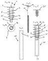
Weitere Einzelheiten und Merkmale der Erfindung ergeben sich aus den Ansprüchen und der nachfolgenden Beschreibung eines in den Zeichnungen dargestellten Ausführungsbeispiels der Erfindung. Es zeigen:
- Fig. 1a
- als Einzelheit eines mehrteiligen Befestigungssystems ein hülsenartiges Halteelement mit oben einer Kopfplatte und unten einem Kupplungsmittel sowie dazwischen liegend einem äußeren Spiralgewinde;
- Fig. 1b
- das hülsenartige Halteelement gemäß
Fig. 1 a in der Draufsicht dargestellt; - Fig. 2
- als Einzelheit des mehrteiligen Befestigungssystems ein an das hülsenartige Halteelement gemäß den Fig. der
Fig. 1 a und 1b zu koppelndes Rohrstück; - Fig. 3
- in einer Gesamtansicht eine selbstschneidende Befestigungsschraube mit im Schraubenkopf ausgebildeter Drehwerkzeugaufnehme;
- Fig. 4
- in einer Gesamtansicht das vorgefertigte Befestigungssystem, bestehend aus dem hülsenartigen Halteelement gemäß den
Fig. 1a und 1b sowie dem Rohrstück gemäßFig. 2 ; - Fig. 5
- einen Verschlussstopfen;
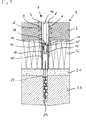
- Fig. 6
- in einem Teillängsschnitt eine mit den Bauteilen der
Fig. 4 mittels der Befestigungsschraube gemäßFig. 3 auf einem Holzuntergrund montierte Holzfaserkombinationsdämmplatte; und - Fig. 7
- in einem Teillängsschnitt eine mit den Bauteilen der
Fig. 4 mittels einer verdübelten Befestigungsschraube auf einem mauerwerkartigen Untergrund montierte Holzfaserkombinationsdämmplatte.
- Fig. 1a
- as a detail of a multi-part fastening system, a sleeve-like holding element with a top plate top and bottom coupling means and intervening an external spiral thread;
- Fig. 1b
- the sleeve-like holding element according to
Fig. 1 a is shown in plan view; - Fig. 2
- as a detail of the multi-part fastening system to the sleeve-like holding element according to the Fig. The
Fig. 1 a and 1b to be coupled pipe section; - Fig. 3
- in an overall view a self-tapping screw with trained trained in the screw head rotary tool;
- Fig. 4
- in an overall view of the prefabricated fastening system, consisting of the sleeve-like holding element according to the
Fig. 1a and 1b and the pipe section according toFig. 2 ; - Fig. 5
- a stopper;
- Fig. 6
- in a partial longitudinal section one with the components of
Fig. 4 by means of the fastening screw according toFig. 3 wood fiber composite insulation board mounted on a wooden background; and - Fig. 7
- in a partial longitudinal section one with the components of
Fig. 4 by means of a dowelled fastening screw on a masonry-like surface mounted Holzfaserkombinationsdämmplatte.
Ein nach
Zum verdrehsicheren Ankoppeln des Rohrstücks 10 an das hülsenartige Halteelement 6 weist dieses ein Außenmehrkant-Kupplungsstück 12 auf, das in eine innerhalb des Rohrstücks 10 ausgebildete Innenmehrkant-Aufnahme 13 eingreift (vgl. hierzu
Des weiteren ist das hülsenartige Halteelement 6, ausgehend von seiner Kopfplatte 7, im Inneren mit einem Innensechskant 14 zur Drehwerkzeugaufnahme ausgebildet (vgl. hierzu
Am unteren Ende ist das hülsenartige Halteelement 6 innenliegend mit einem konischen Aufnahmesitz 15 für einen Senkkopf 16 der selbstschneidenden Befestigungsschraube 11 versehen. Der Senkkopf 16 der Befestigungsschraube 11 weist ebenfalls eine Drehwerkzeugaufnahme 17, beispielsweise ausgebildet als Kreuzschlitz, auf (vgl. hierzu
Mit dem vorstehend beschriebenen, mehrteiligen Befestigungssystem 1 wird die Holzfaserkombinationsdämmplatte 2 wie nachstehend näher erläutert auf dem Holzuntergrund 5 angebracht.With the
Zuerst wird ein Loch 18 im Maß des Kerndurchmessers bzw. der Seele 19 des hülsenartigen Halteelementes 6 bzw. dessen Hülsenteils 8 und des angekoppelten Rohrstücks 10 in die äußere, härtere Materialschicht 3 gebohrt.First, a
Anschließend wird das mit dem Rohrstück 10 gekoppelte Halteelement 6 so weit in das vorgebohrte Loch 18 eingesteckt, bis das in Einschraubrichtung vordere Gewindeende 20 des sich von der Kopfplatte 7 nach unten hin konisch verjüngenden Spiralgewindes 9 auf der äußeren, härteren Materialschicht 3 zur Anlage kommt.Subsequently, the coupled with the
Nachfolgend wird durch Einsetzen eines nicht dargestellten Montage- bzw. Drehwerkzeugs in den Innensechskant bzw. die mehrkantige Durchführung 14 das hülsenartige Halteelement 6 über sein Spiralgewinde 9 in die äußere, härtere Materialschicht 3 eingeschraubt, bis die Kopfplatte 7 auf der äußeren, härteren Materialschicht zur Anlage kommt. Einhergehend damit hat sich das Rohrstück 10 durch die innere, weichere Faserschicht 4 der Holzfaserkombinationsdämmplatte 2 hindurchgedrückt und liegt am Holzuntergrund 5 an, ohne dass dabei die innere, weichere Faserschicht 4 zusammengepresst werden kann.Subsequently, the sleeve-
Abschließend wird die selbstschneidende Befestigungsschraube 11 durch das hülsenartige Halteelement 6 und das Rohrstück 10 hindurchgesteckt und mittels eines hier nicht dargestellten Kreuzschraubendrehers oder dergleichen so weit in den Holzuntergrund 5 eingeschraubt, bis der Senkkopf 16 in dem konischen Aufnahmesitz 15 aufliegt und das hülsenartige Halteelement 6 mit dem Rohrstück 10 fest gegen den Holzuntergrund 5 verschraubt ist.Finally, the self-tapping
Die in
Hierzu wird ergänzend zu dem Loch 18 der Holzfaserkombinationsdämmplatte 2 in die Aufputzschicht 21 und in den mauerwerkartigen Untergrund 22 ein Loch 23 entsprechend dem Durchmesser eines Dübels 24 gebohrt. Anschließend wird die Befestigungsschraube 11 zusammen mit dem Dübel 24 durch das schon eingebrachte hülsenartige Halteelement 6 samt Rohrstück 10 hindurchgesteckt, wobei der Dübel 24 in das vorgebohrte Loch 23 eintaucht. Nachfolgend wird die mit einem in ihrem Senkkopf 16 ausgebildeten Kreuzschlitz versehene Befestigungsschraube 11 mittels eines Kreuzschraubendrehers oder dergleichen Montagewerkzeug in den Dübel 24 hineingedreht, wodurch sich dieser verankernd im mauerwerkartigen Untergrund 22 aufspreizt.For this purpose, a
Nach dem vollständigen Eindrehen der Befestigungsschraube 11, wobei der Senkkopf 16 in dem konischen Aufnahmesitz 15 aufliegt, ist die Holzfaserkombinationsdämmplatte 2 bewegungssicher zwischen der Kopfplatte 7 und dem mauerwerkartigen Untergrund 22 bzw. der Aufputzschicht 21 festgelegt.After complete screwing in the
Abschließend kann die Durchführung 14 der Kopfplatte 7 mit einem in ihren Innensechskant hineindrückbaren Abdeckstopfen 25, wie in
- 11
- mehrteiliges Befestigungssystemmulti-part fastening system
- 22
- Holzfaserkombinationsdämmplatte/DämmstoffplatteHolzfaserkombinationsdämmplatte / insulation board
- 33
- äußere, härtere Materialschichtouter, harder material layer
- 44
- innere, weichere Faserschichtinner, softer fiber layer
- 55
- HolzuntergrundWooden background
- 66
- hülsenartiges Halteelementsleeve-like holding element
- 77
- Kopfplatteheadstock
- 88th
- Hülsenteilsleeve part
- 99
- Spiralgewindespiral thread
- 1010
- Rohrstückpipe section
- 1111
- selbstschneidende Befestigungsschraubeself-tapping fastening screw
- 1212
- Außenmehrkant-Kupplungsstück/KupplungsmittelExternal polygon-coupler / coupling agent
- 1313
- Innenmehrkant-AufnahmeInternal polygon Recording
- 1414
- Innensechskant/DurchführungAllen / implementation
- 1515
- konischer Aufnahmesitzconical seat
- 1616
- Senkkopf/SchraubenkopfCountersunk / screw head
- 1717
- DrehwerkzeugaufnahmeRotary tool holder
- 1818
- Lochhole
- 1919
- Kerndurchmesser/SeeleCore diameter / soul
- 2020
- vorderes Gewindeendefront threaded end
- 2121
- AufputzschichtSurface layer
- 2222
- mauerwerkartiger Untergrundmasonry-like background
- 2323
- Lochhole
- 2424
- Dübeldowel
- 2525
- AbdeckstopfenCover plug
Claims (8)
- A method for mounting insulating boards (2) or similar insulating materials on a substructure (5, 22), with a fastening system comprising a sleeve element (6) that is realized with a top plate (7) and a cutting helix in the form of a spiral screw thread (9), which is integrally formed on the sleeve element, wherein the sleeve element (6) is provided with a multi-sided screw driving socket (14) for attaching an installation tool in a torque-proof fashion on its upper end referred to the installation direction, and a fastening means (11) that extends through the sleeve element (6) and can be anchored in the substructure (5, 22), if applicable, with the aid of an anchor fitting (24), wherein the top of said fastening means is also designed for attaching the installation tool in a torque-proof fashion,
characterized in
that an insulating board (2) with a harder outer material layer (3) and a softer inner fiber layer (4) is mounted by initially producing a hole (18) with the dimension of the bore (19) of the sleeve-like retaining element (6) and a tube section (10), which has the same outside diameter and is connected to the retaining element (6), in the harder outer material layer (3) in a first step, subsequently inserting the retaining element (6) connected to the tube section (10) into the pre-drilled hole (18) until the free front end (20) of the spiral screw thread (9) referred to the screw-in direction comes in contact with the harder outer material layer (3) in a second step, and ultimately screwing the retaining element (6) into the harder outer material layer (3) by means of the installation tool until the top plate (7) integrally formed on the retaining element (6) bears on the harder outer material layer (3) in a third step, wherein the tube section (10) is brought in contact with the substructure (5, 22). - The method according to claim 1,
characterized in
that the wood fiber combination insulating board (2) is mounted on a masonry-like substructure (22) by initially drilling a hole (23) corresponding to the diameter of an anchor fitting (24) used as far as into the masonry (22). - A fastening system for mounting insulating boards (2) or similar insulating materials on a substructure (5, 22), comprising a sleeve element (6) that is realized with a top plate (7) and a cutting helix in the form of a spiral screw thread (9), which is integrally formed on the sleeve element, wherein the sleeve element (6) is provided with a multi-sided screw driving socket (14) for attaching an installation tool in a torque-proof fashion on its upper end referred to the installation direction, and a fastening means (11) that extends through the sleeve element (6) and can be anchored in the substructure (5, 22), if applicable, with the aid of an anchor fitting (24), wherein the top of said fastening means is also realized for attaching the installation tool in a torque-proof fashion, particularly for carrying out the method according to claim 1,
characterized in
that the fastening system (1) for mounting wood fiber combination insulating boards (2) is composed of multiple parts and comprises the sleeve-like retaining element (6) provided with the top plate (7) on its upper end, wherein the retaining element (6) is on the one hand designed without a connection to the cutting helix in the form of a spiral screw thread (9) and on the other hand realized with a coupling element (12) on its front end referred to the screw-in direction, a tube section (10) that is coupled to the retaining element (6) by means of the coupling element (12) and a fastening means (11) that can be inserted through the sleeve-like retaining element (6) with the coupled tube section (10). - The fastening system according to claim 3,
characterized in
that the cutting helix in the form of a spiral screw thread (9) is designed without a connection to the top plate (7). - The fastening system according to claim 3 or 4,
characterized in
that the multi-part fastening system (1) can be supplemented with an anchor fitting (24) that can be expanded by the fastening means (11). - The fastening system according to one of claims 3-5,
characterized in
that the outer flights of the spiral screw thread (9) are conically tapered from the top toward the bottom. - The fastening system according to one of claims 3 to 6,
characterized in
that the sleeve-like retaining element (6) is starting at the top plate (7) designed with multiple stages referred to the screw-in or installation direction and features the multi-sided socket (14) for receiving the installation tool in a first region, a receptacle seat (15) for a screw head (16) of the fastening means (11) in a second region and the coupling element (12) on its end. - The fastening system according to one of claims 3 to 7,
characterized in
that the top plate (7) of the sleeve-like retaining element (6) can be sealed with a plug (25).
Applications Claiming Priority (1)
| Application Number | Priority Date | Filing Date | Title |
|---|---|---|---|
| DE102012010009 | 2012-05-22 |
Publications (3)
| Publication Number | Publication Date |
|---|---|
| EP2666919A2 EP2666919A2 (en) | 2013-11-27 |
| EP2666919A3 EP2666919A3 (en) | 2014-06-18 |
| EP2666919B1 true EP2666919B1 (en) | 2015-12-16 |
Family
ID=48534116
Family Applications (1)
| Application Number | Title | Priority Date | Filing Date |
|---|---|---|---|
| EP13002663.6A Active EP2666919B1 (en) | 2012-05-22 | 2013-05-22 | Method and mounting system for attaching insulation panels to a support surface |
Country Status (1)
| Country | Link |
|---|---|
| EP (1) | EP2666919B1 (en) |
Cited By (1)
| Publication number | Priority date | Publication date | Assignee | Title |
|---|---|---|---|---|
| EP3150773B1 (en) * | 2015-10-02 | 2024-01-31 | URSA Insulation, S.A. | Improved method for fixation of an insulation element to a structural element of a building, and spacer fastening device suitable for use in such a method |
Families Citing this family (7)
| Publication number | Priority date | Publication date | Assignee | Title |
|---|---|---|---|---|
| FI128405B (en) * | 2014-10-23 | 2020-04-30 | Sk Tuote Oy | Method for fastening insulation materials using a sleeve, and sleeve and fastening system |
| EP3101188B1 (en) * | 2015-06-02 | 2019-11-20 | RANIT-Befestigungssysteme GmbH | Insulation mount for fastening insulation panels to a substrate |
| ES2955352T3 (en) | 2015-10-02 | 2023-11-30 | Ursa Insulation Sa | Improved building roof or wall system comprising fibrous insulation |
| CN106193472B (en) * | 2016-08-29 | 2018-07-13 | 河南农业大学 | A kind of thermal insulation of roof waterproof fixed structure |
| ES2790595T3 (en) | 2017-01-13 | 2020-10-28 | Ursa Insulation Sa | Insulation system with glass wool insulating elements and method for their separate fixing |
| EP4006246A1 (en) | 2020-11-30 | 2022-06-01 | URSA Insulation, S.A. | Insulating structure and method for manufacturing such an insulating structure |
| EP4006247A1 (en) | 2020-11-30 | 2022-06-01 | URSA Insulation, S.A. | Method for modifying the insulation of an insulated rigid construction |
Family Cites Families (5)
| Publication number | Priority date | Publication date | Assignee | Title |
|---|---|---|---|---|
| WO1993016291A1 (en) * | 1992-02-11 | 1993-08-19 | Ramset Fasteners (Aust.) Pty. Limited | Masonry anchors |
| DE4407349A1 (en) * | 1994-03-05 | 1995-09-07 | Toge Duebel A Gerhard Gmbh | Expansion fixing for holding insulation board on to brickwork |
| EP2068007B1 (en) | 2007-12-05 | 2012-02-01 | RANIT-Befestigungssysteme GmbH | Method and fixing system for attaching insulating boards, a dowel and a retainer |
| DE102008010606A1 (en) * | 2008-02-22 | 2009-08-27 | Fischerwerke Gmbh & Co. Kg | Fastening element for wood fiber insulation panels |
| DE202009012420U1 (en) * | 2009-09-15 | 2009-11-19 | Sieber, Dieter | Mounting system for insulating panels |
-
2013
- 2013-05-22 EP EP13002663.6A patent/EP2666919B1/en active Active
Cited By (1)
| Publication number | Priority date | Publication date | Assignee | Title |
|---|---|---|---|---|
| EP3150773B1 (en) * | 2015-10-02 | 2024-01-31 | URSA Insulation, S.A. | Improved method for fixation of an insulation element to a structural element of a building, and spacer fastening device suitable for use in such a method |
Also Published As
| Publication number | Publication date |
|---|---|
| EP2666919A3 (en) | 2014-06-18 |
| EP2666919A2 (en) | 2013-11-27 |
Similar Documents
| Publication | Publication Date | Title |
|---|---|---|
| EP2666919B1 (en) | Method and mounting system for attaching insulation panels to a support surface | |
| EP1978177B1 (en) | Spacer for fixing a supporting element to a wall | |
| DE102005022449A1 (en) | Spacer for the attachment of an object to a substrate having an insulating layer | |
| DE102006017459A1 (en) | Spacer for attaching e.g. mailbox to wall, has insulating layer with anchor bolt having retainer for fastening part, where anchor bolt is made of fiber-reinforced plastic and retainer is formed by borehole | |
| EP2992226B1 (en) | Anchor system | |
| DE102012101320A1 (en) | Screw and thin sheet metal connection made therewith | |
| EP2068007A2 (en) | Method and fixing system for attaching insulating boards, a dowel and a retainer | |
| DE19846204C2 (en) | Fastening element and method for fastening insulation sheets or panels on a solid substructure, in particular in the roof area of buildings | |
| EP2397705B1 (en) | Anchoring system for distanced tension-free mounting of an element to an anchoring base | |
| EP3540160B1 (en) | Fastening arrangement for fastening a door hinge on a hollow profile | |
| EP3421678B1 (en) | Method for the application of insulating panels and fixing system for the same | |
| EP2466024B1 (en) | Anchor and fastening device for thermally insulated walls | |
| DE202007009225U1 (en) | bridge plugs | |
| DE102006003172A1 (en) | Anchor plug used for fixings to concrete has threaded external profile and internal threaded bore | |
| EP2251555A1 (en) | Dowel | |
| DE102008058512A1 (en) | Insulation board attaching method for use in underground, involves moving retaining plate to end position with pressing of insulation boards relative to dowel during rotary motion of fastening unit, where movement of plate is limited | |
| DE202009012420U1 (en) | Mounting system for insulating panels | |
| DE102007053740B3 (en) | Fixing element for assembling in an insulating material comprises a plastic spiral having a two-channel holding chamber | |
| DE102007044981B4 (en) | Supporting structure and method for anchoring supporting structures | |
| DE19537000C1 (en) | Method for the adjustable fastening of slats, rails, plates or the like to a solid surface and fastening element for carrying out the method | |
| DE3611873A1 (en) | Fastening element for the adjustable fastening of structural elements on structures | |
| DE102009044229B3 (en) | A fitting for adjusting a distance between a component and a substructure, and a system and method therefor | |
| DE102007001426A1 (en) | Fastening device for guttering and lightening rods on fronts of buildings has a strong thermal protection and a rubber sleeve | |
| DE102007043568A1 (en) | Fixing element for fixing rawlplug in hollow building material i.e. brick, has screwing element comprising spreading thread section that is provided between screwing element head and screwing element shaft of screwing element | |
| EP2784243A1 (en) | Method and fastening system for attaching an insulating panel to masonry |
Legal Events
| Date | Code | Title | Description |
|---|---|---|---|
| PUAI | Public reference made under article 153(3) epc to a published international application that has entered the european phase |
Free format text: ORIGINAL CODE: 0009012 |
|
| AK | Designated contracting states |
Kind code of ref document: A2 Designated state(s): AL AT BE BG CH CY CZ DE DK EE ES FI FR GB GR HR HU IE IS IT LI LT LU LV MC MK MT NL NO PL PT RO RS SE SI SK SM TR |
|
| AX | Request for extension of the european patent |
Extension state: BA ME |
|
| PUAL | Search report despatched |
Free format text: ORIGINAL CODE: 0009013 |
|
| AK | Designated contracting states |
Kind code of ref document: A3 Designated state(s): AL AT BE BG CH CY CZ DE DK EE ES FI FR GB GR HR HU IE IS IT LI LT LU LV MC MK MT NL NO PL PT RO RS SE SI SK SM TR |
|
| AX | Request for extension of the european patent |
Extension state: BA ME |
|
| RIC1 | Information provided on ipc code assigned before grant |
Ipc: E04B 1/76 20060101AFI20140509BHEP |
|
| 17P | Request for examination filed |
Effective date: 20141204 |
|
| RBV | Designated contracting states (corrected) |
Designated state(s): AL AT BE BG CH CY CZ DE DK EE ES FI FR GB GR HR HU IE IS IT LI LT LU LV MC MK MT NL NO PL PT RO RS SE SI SK SM TR |
|
| REG | Reference to a national code |
Ref country code: DE Ref legal event code: R079 Ref document number: 502013001621 Country of ref document: DE Free format text: PREVIOUS MAIN CLASS: E04B0001760000 Ipc: E04D0003360000 |
|
| GRAP | Despatch of communication of intention to grant a patent |
Free format text: ORIGINAL CODE: EPIDOSNIGR1 |
|
| INTG | Intention to grant announced |
Effective date: 20150611 |
|
| RIC1 | Information provided on ipc code assigned before grant |
Ipc: E04B 1/76 20060101ALI20150529BHEP Ipc: E04D 3/36 20060101AFI20150529BHEP |
|
| GRAS | Grant fee paid |
Free format text: ORIGINAL CODE: EPIDOSNIGR3 |
|
| GRAA | (expected) grant |
Free format text: ORIGINAL CODE: 0009210 |
|
| AK | Designated contracting states |
Kind code of ref document: B1 Designated state(s): AL AT BE BG CH CY CZ DE DK EE ES FI FR GB GR HR HU IE IS IT LI LT LU LV MC MK MT NL NO PL PT RO RS SE SI SK SM TR |
|
| REG | Reference to a national code |
Ref country code: GB Ref legal event code: FG4D Free format text: NOT ENGLISH |
|
| REG | Reference to a national code |
Ref country code: CH Ref legal event code: EP |
|
| REG | Reference to a national code |
Ref country code: IE Ref legal event code: FG4D Free format text: LANGUAGE OF EP DOCUMENT: GERMAN |
|
| REG | Reference to a national code |
Ref country code: AT Ref legal event code: REF Ref document number: 765636 Country of ref document: AT Kind code of ref document: T Effective date: 20160115 |
|
| REG | Reference to a national code |
Ref country code: DE Ref legal event code: R096 Ref document number: 502013001621 Country of ref document: DE |
|
| REG | Reference to a national code |
Ref country code: NL Ref legal event code: MP Effective date: 20151216 |
|
| REG | Reference to a national code |
Ref country code: LT Ref legal event code: MG4D |
|
| PG25 | Lapsed in a contracting state [announced via postgrant information from national office to epo] |
Ref country code: LT Free format text: LAPSE BECAUSE OF FAILURE TO SUBMIT A TRANSLATION OF THE DESCRIPTION OR TO PAY THE FEE WITHIN THE PRESCRIBED TIME-LIMIT Effective date: 20151216 Ref country code: NO Free format text: LAPSE BECAUSE OF FAILURE TO SUBMIT A TRANSLATION OF THE DESCRIPTION OR TO PAY THE FEE WITHIN THE PRESCRIBED TIME-LIMIT Effective date: 20160316 Ref country code: HR Free format text: LAPSE BECAUSE OF FAILURE TO SUBMIT A TRANSLATION OF THE DESCRIPTION OR TO PAY THE FEE WITHIN THE PRESCRIBED TIME-LIMIT Effective date: 20151216 |
|
| PG25 | Lapsed in a contracting state [announced via postgrant information from national office to epo] |
Ref country code: RS Free format text: LAPSE BECAUSE OF FAILURE TO SUBMIT A TRANSLATION OF THE DESCRIPTION OR TO PAY THE FEE WITHIN THE PRESCRIBED TIME-LIMIT Effective date: 20151216 Ref country code: LV Free format text: LAPSE BECAUSE OF FAILURE TO SUBMIT A TRANSLATION OF THE DESCRIPTION OR TO PAY THE FEE WITHIN THE PRESCRIBED TIME-LIMIT Effective date: 20151216 Ref country code: SE Free format text: LAPSE BECAUSE OF FAILURE TO SUBMIT A TRANSLATION OF THE DESCRIPTION OR TO PAY THE FEE WITHIN THE PRESCRIBED TIME-LIMIT Effective date: 20151216 Ref country code: GR Free format text: LAPSE BECAUSE OF FAILURE TO SUBMIT A TRANSLATION OF THE DESCRIPTION OR TO PAY THE FEE WITHIN THE PRESCRIBED TIME-LIMIT Effective date: 20160317 Ref country code: FI Free format text: LAPSE BECAUSE OF FAILURE TO SUBMIT A TRANSLATION OF THE DESCRIPTION OR TO PAY THE FEE WITHIN THE PRESCRIBED TIME-LIMIT Effective date: 20151216 Ref country code: NL Free format text: LAPSE BECAUSE OF FAILURE TO SUBMIT A TRANSLATION OF THE DESCRIPTION OR TO PAY THE FEE WITHIN THE PRESCRIBED TIME-LIMIT Effective date: 20151216 |
|
| PG25 | Lapsed in a contracting state [announced via postgrant information from national office to epo] |
Ref country code: ES Free format text: LAPSE BECAUSE OF FAILURE TO SUBMIT A TRANSLATION OF THE DESCRIPTION OR TO PAY THE FEE WITHIN THE PRESCRIBED TIME-LIMIT Effective date: 20151216 Ref country code: CZ Free format text: LAPSE BECAUSE OF FAILURE TO SUBMIT A TRANSLATION OF THE DESCRIPTION OR TO PAY THE FEE WITHIN THE PRESCRIBED TIME-LIMIT Effective date: 20151216 |
|
| PG25 | Lapsed in a contracting state [announced via postgrant information from national office to epo] |
Ref country code: BE Free format text: LAPSE BECAUSE OF NON-PAYMENT OF DUE FEES Effective date: 20160531 Ref country code: SK Free format text: LAPSE BECAUSE OF FAILURE TO SUBMIT A TRANSLATION OF THE DESCRIPTION OR TO PAY THE FEE WITHIN THE PRESCRIBED TIME-LIMIT Effective date: 20151216 Ref country code: PT Free format text: LAPSE BECAUSE OF FAILURE TO SUBMIT A TRANSLATION OF THE DESCRIPTION OR TO PAY THE FEE WITHIN THE PRESCRIBED TIME-LIMIT Effective date: 20160418 Ref country code: RO Free format text: LAPSE BECAUSE OF FAILURE TO SUBMIT A TRANSLATION OF THE DESCRIPTION OR TO PAY THE FEE WITHIN THE PRESCRIBED TIME-LIMIT Effective date: 20151216 Ref country code: IS Free format text: LAPSE BECAUSE OF FAILURE TO SUBMIT A TRANSLATION OF THE DESCRIPTION OR TO PAY THE FEE WITHIN THE PRESCRIBED TIME-LIMIT Effective date: 20160416 Ref country code: EE Free format text: LAPSE BECAUSE OF FAILURE TO SUBMIT A TRANSLATION OF THE DESCRIPTION OR TO PAY THE FEE WITHIN THE PRESCRIBED TIME-LIMIT Effective date: 20151216 Ref country code: SM Free format text: LAPSE BECAUSE OF FAILURE TO SUBMIT A TRANSLATION OF THE DESCRIPTION OR TO PAY THE FEE WITHIN THE PRESCRIBED TIME-LIMIT Effective date: 20151216 |
|
| REG | Reference to a national code |
Ref country code: DE Ref legal event code: R097 Ref document number: 502013001621 Country of ref document: DE |
|
| PLBE | No opposition filed within time limit |
Free format text: ORIGINAL CODE: 0009261 |
|
| STAA | Information on the status of an ep patent application or granted ep patent |
Free format text: STATUS: NO OPPOSITION FILED WITHIN TIME LIMIT |
|
| PG25 | Lapsed in a contracting state [announced via postgrant information from national office to epo] |
Ref country code: PL Free format text: LAPSE BECAUSE OF FAILURE TO SUBMIT A TRANSLATION OF THE DESCRIPTION OR TO PAY THE FEE WITHIN THE PRESCRIBED TIME-LIMIT Effective date: 20151216 Ref country code: DK Free format text: LAPSE BECAUSE OF FAILURE TO SUBMIT A TRANSLATION OF THE DESCRIPTION OR TO PAY THE FEE WITHIN THE PRESCRIBED TIME-LIMIT Effective date: 20151216 |
|
| 26N | No opposition filed |
Effective date: 20160919 |
|
| PG25 | Lapsed in a contracting state [announced via postgrant information from national office to epo] |
Ref country code: LU Free format text: LAPSE BECAUSE OF FAILURE TO SUBMIT A TRANSLATION OF THE DESCRIPTION OR TO PAY THE FEE WITHIN THE PRESCRIBED TIME-LIMIT Effective date: 20160522 |
|
| REG | Reference to a national code |
Ref country code: CH Ref legal event code: PL |
|
| PG25 | Lapsed in a contracting state [announced via postgrant information from national office to epo] |
Ref country code: CH Free format text: LAPSE BECAUSE OF NON-PAYMENT OF DUE FEES Effective date: 20160531 Ref country code: LI Free format text: LAPSE BECAUSE OF NON-PAYMENT OF DUE FEES Effective date: 20160531 |
|
| REG | Reference to a national code |
Ref country code: IE Ref legal event code: MM4A |
|
| PG25 | Lapsed in a contracting state [announced via postgrant information from national office to epo] |
Ref country code: SI Free format text: LAPSE BECAUSE OF FAILURE TO SUBMIT A TRANSLATION OF THE DESCRIPTION OR TO PAY THE FEE WITHIN THE PRESCRIBED TIME-LIMIT Effective date: 20151216 |
|
| REG | Reference to a national code |
Ref country code: FR Ref legal event code: ST Effective date: 20170131 |
|
| PG25 | Lapsed in a contracting state [announced via postgrant information from national office to epo] |
Ref country code: FR Free format text: LAPSE BECAUSE OF NON-PAYMENT OF DUE FEES Effective date: 20160531 |
|
| PG25 | Lapsed in a contracting state [announced via postgrant information from national office to epo] |
Ref country code: IE Free format text: LAPSE BECAUSE OF NON-PAYMENT OF DUE FEES Effective date: 20160522 |
|
| GBPC | Gb: european patent ceased through non-payment of renewal fee |
Effective date: 20170522 |
|
| PG25 | Lapsed in a contracting state [announced via postgrant information from national office to epo] |
Ref country code: GB Free format text: LAPSE BECAUSE OF NON-PAYMENT OF DUE FEES Effective date: 20170522 |
|
| PG25 | Lapsed in a contracting state [announced via postgrant information from national office to epo] |
Ref country code: HU Free format text: LAPSE BECAUSE OF FAILURE TO SUBMIT A TRANSLATION OF THE DESCRIPTION OR TO PAY THE FEE WITHIN THE PRESCRIBED TIME-LIMIT; INVALID AB INITIO Effective date: 20130522 Ref country code: CY Free format text: LAPSE BECAUSE OF FAILURE TO SUBMIT A TRANSLATION OF THE DESCRIPTION OR TO PAY THE FEE WITHIN THE PRESCRIBED TIME-LIMIT Effective date: 20151216 |
|
| PG25 | Lapsed in a contracting state [announced via postgrant information from national office to epo] |
Ref country code: TR Free format text: LAPSE BECAUSE OF FAILURE TO SUBMIT A TRANSLATION OF THE DESCRIPTION OR TO PAY THE FEE WITHIN THE PRESCRIBED TIME-LIMIT Effective date: 20151216 Ref country code: MC Free format text: LAPSE BECAUSE OF FAILURE TO SUBMIT A TRANSLATION OF THE DESCRIPTION OR TO PAY THE FEE WITHIN THE PRESCRIBED TIME-LIMIT Effective date: 20151216 Ref country code: MT Free format text: LAPSE BECAUSE OF FAILURE TO SUBMIT A TRANSLATION OF THE DESCRIPTION OR TO PAY THE FEE WITHIN THE PRESCRIBED TIME-LIMIT Effective date: 20151216 Ref country code: MK Free format text: LAPSE BECAUSE OF FAILURE TO SUBMIT A TRANSLATION OF THE DESCRIPTION OR TO PAY THE FEE WITHIN THE PRESCRIBED TIME-LIMIT Effective date: 20151216 |
|
| PG25 | Lapsed in a contracting state [announced via postgrant information from national office to epo] |
Ref country code: BG Free format text: LAPSE BECAUSE OF FAILURE TO SUBMIT A TRANSLATION OF THE DESCRIPTION OR TO PAY THE FEE WITHIN THE PRESCRIBED TIME-LIMIT Effective date: 20151216 |
|
| PG25 | Lapsed in a contracting state [announced via postgrant information from national office to epo] |
Ref country code: AL Free format text: LAPSE BECAUSE OF FAILURE TO SUBMIT A TRANSLATION OF THE DESCRIPTION OR TO PAY THE FEE WITHIN THE PRESCRIBED TIME-LIMIT Effective date: 20151216 |
|
| PGFP | Annual fee paid to national office [announced via postgrant information from national office to epo] |
Ref country code: IT Payment date: 20221026 Year of fee payment: 10 |
|
| P01 | Opt-out of the competence of the unified patent court (upc) registered |
Effective date: 20230517 |
|
| PGFP | Annual fee paid to national office [announced via postgrant information from national office to epo] |
Ref country code: AT Payment date: 20231002 Year of fee payment: 11 |
|
| PGFP | Annual fee paid to national office [announced via postgrant information from national office to epo] |
Ref country code: DE Payment date: 20230929 Year of fee payment: 11 |