DE102007044981B4 - Supporting structure and method for anchoring supporting structures - Google Patents
Supporting structure and method for anchoring supporting structures Download PDFInfo
- Publication number
- DE102007044981B4 DE102007044981B4 DE200710044981 DE102007044981A DE102007044981B4 DE 102007044981 B4 DE102007044981 B4 DE 102007044981B4 DE 200710044981 DE200710044981 DE 200710044981 DE 102007044981 A DE102007044981 A DE 102007044981A DE 102007044981 B4 DE102007044981 B4 DE 102007044981B4
- Authority
- DE
- Germany
- Prior art keywords
- supporting structure
- thread
- ground
- screwed
- fastening bolt
- Prior art date
- Legal status (The legal status is an assumption and is not a legal conclusion. Google has not performed a legal analysis and makes no representation as to the accuracy of the status listed.)
- Active
Links
Classifications
-
- E—FIXED CONSTRUCTIONS
- E04—BUILDING
- E04F—FINISHING WORK ON BUILDINGS, e.g. STAIRS, FLOORS
- E04F13/00—Coverings or linings, e.g. for walls or ceilings
- E04F13/07—Coverings or linings, e.g. for walls or ceilings composed of covering or lining elements; Sub-structures therefor; Fastening means therefor
- E04F13/08—Coverings or linings, e.g. for walls or ceilings composed of covering or lining elements; Sub-structures therefor; Fastening means therefor composed of a plurality of similar covering or lining elements
- E04F13/0801—Separate fastening elements
- E04F13/0803—Separate fastening elements with load-supporting elongated furring elements between wall and covering elements
-
- E—FIXED CONSTRUCTIONS
- E04—BUILDING
- E04F—FINISHING WORK ON BUILDINGS, e.g. STAIRS, FLOORS
- E04F10/00—Sunshades, e.g. Florentine blinds or jalousies; Outside screens; Awnings or baldachins
- E04F10/02—Sunshades, e.g. Florentine blinds or jalousies; Outside screens; Awnings or baldachins of flexible canopy materials, e.g. canvas ; Baldachins
- E04F10/06—Sunshades, e.g. Florentine blinds or jalousies; Outside screens; Awnings or baldachins of flexible canopy materials, e.g. canvas ; Baldachins comprising a roller-blind with means for holding the end away from a building
- E04F10/0662—Sunshades, e.g. Florentine blinds or jalousies; Outside screens; Awnings or baldachins of flexible canopy materials, e.g. canvas ; Baldachins comprising a roller-blind with means for holding the end away from a building with arrangements for fastening the blind to the building
Abstract
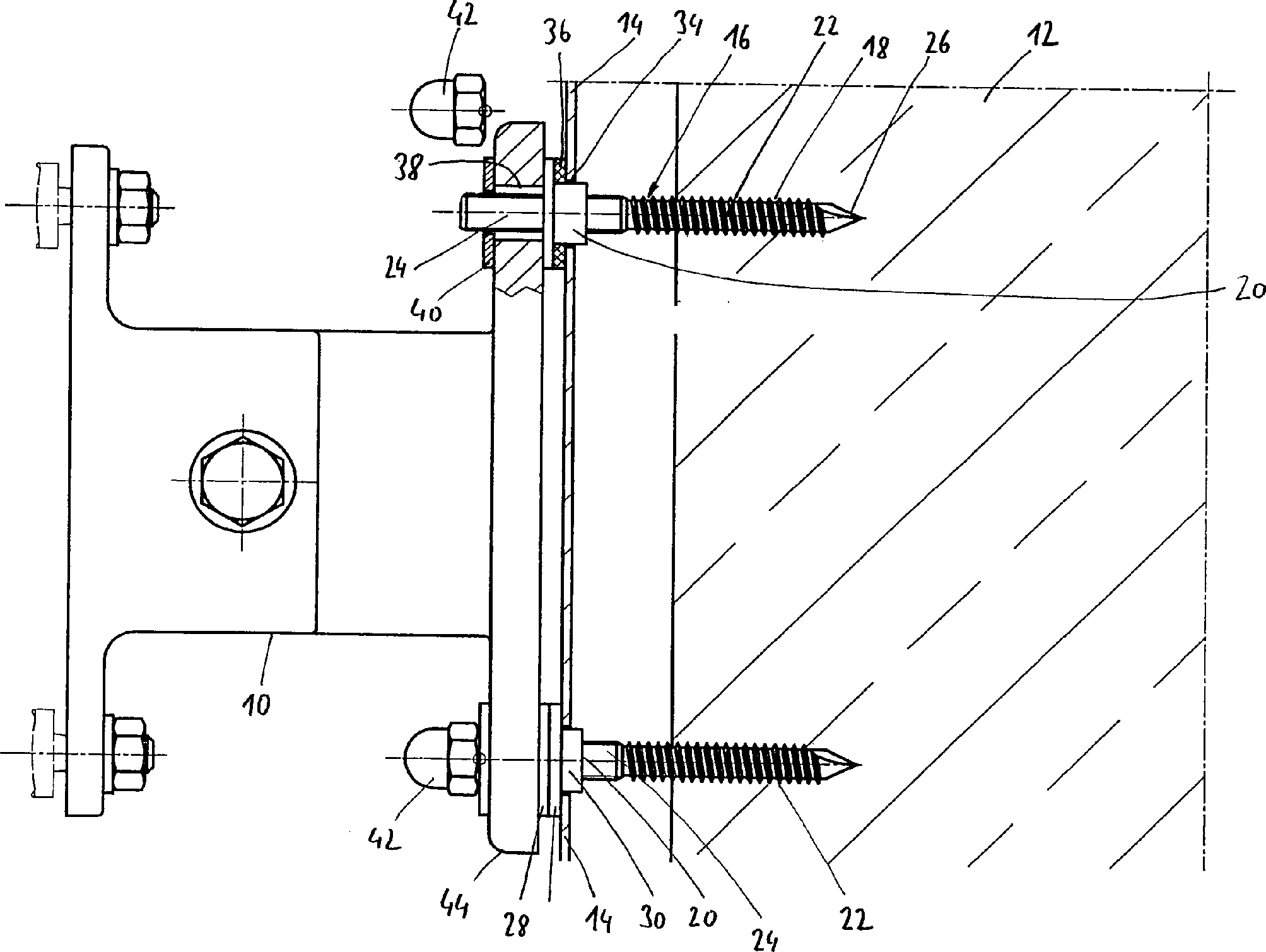
Tragkonstruktion (10, 44) mit einem Befestigungsbolzen und einem mit einer Blende (14) verkleideten Untergrund (12), wobei die Blende (14) in einem bestimmten Abstand zum Untergrund (12) liegt und der Befestigungsbolzen (16) einen ersten Gewindeabschnitt (22) zum Einschrauben in den Untergrund (12) und an seinem entgegensetzten Ende einen zweiten Gewindeabschnitt (24) in der Form eines Maschinengewindes zum Anschrauben der Tragkonstruktion (10, 44) aufweist, dadurch gekennzeichnet, dass der Befestigungsbolzen (16) einen sich über den Umfang erstreckenden Anschlag (28) aufweist, der auf einer Seite zur Anlage an der Blendenoberfläche ein Dichtelement (36) aufweist, mit welchem eine Durchgangsbohrung (34) in der Blende (14) abdichtbar ist, durch welche der Befestigungsbolzen (16) in den Untergrund (12) einschraubbar ist, wobei der Anschlag (28) an einem separaten Element (20) mit einem Innengewinde (32) ausgebildet ist, mit welchem dieses auf das Maschinengewinde (24) des Befestigungsbolzens (16) aufdrehbar ist.Supporting structure (10, 44) having a fastening bolt and a base (12) clad with a panel (14), the panel (14) being at a certain distance from the ground (12) and the fastening bolt (16) having a first threaded portion (22 ) for screwing into the base (12) and at its opposite end a second threaded portion (24) in the form of a machine thread for screwing the support structure (10, 44), characterized in that the fastening bolt (16) extends over the circumference extending stop (28) having on one side to rest against the diaphragm surface, a sealing element (36), with which a through hole (34) in the diaphragm (14) is sealable, through which the fastening bolt (16) into the ground ( 12) can be screwed, wherein the stop (28) on a separate element (20) with an internal thread (32) is formed, with which this on the machine thread (24) of the Befestigungsb olzens (16) is aufdrehbar.
Description
Die vorliegende Erfindung befasst sich mit einer Tragkonstruktion mit Befestigungsbolzen und einem mit einer Blende verkleideten Untergrund, wobei die Blende in einem bestimmten Abstand zum Untergrund liegt und der Befestigungsbolzen einen ersten Gewindeabschnitt zum Einschrauben in den Untergrund und an seinem entgegengesetzten Ende einen zweiten Geschwindeabschnitt in der Form eines Maschinengewindes zum Anschrauben der Tragkonstruktion aufweist.The The present invention is concerned with a support structure Fixing bolts and a panel clad with a panel, the aperture is at a certain distance from the ground and the fastening bolt a first threaded portion for screwing in the underground and at its opposite end a second Velocity section in the form of a machine thread for screwing having the support structure.
Insbesondere im Bereich von Fassaden begegnet man häufig dem Problem, dass der Fassadenuntergrund, beispielsweise Beton, Stahlkonstruktionen oder Holzuntergrund durch eine Blende verkleidet ist, die in einem bestimmten Abstand zum Untergrund liegt und selbst nicht durch Kräfte belastet werden darf. Gleichwohl ist es gewünscht, die Durchdringstellen in der Blende abzudichten, um das Eindringen von Feuchtigkeit zu verhindern, die in dem geschlossenen Raum zwischen der Blende und dem Untergrund auf die Dauer beträchtlichen Schaden anrichten kann.Especially In the field of facades one often encounters the problem that the Facade substructure, for example concrete, steel structures or Wooden background is covered by a panel, which in a particular Distance to the ground is located and not burdened by forces may be. Nevertheless, it is desirable to have the penetration points in the panel to prevent the ingress of moisture prevent in the closed space between the aperture and cause considerable damage to the subsoil in the long term can.
Als Lösung ist es bekannt, einen einfachen Gewindebolzen, dessen eines Ende in seiner Gewindeform an den Untergrund angepasst sein kann, durch eine Durchgangsbohrung in der Blende in der Untergrund einzuschrauben und an dem hervorstehenden Maschinengewinde schließlich die Tragkonstruktion zwischen zwei Kontermuttern zu verklemmen. Problematisch ist zum einen das Abdichten der an die Blende angrenzenden Kontermutter, der durch handelsübliche Mutternhöhen bedingte relativ große Abstand zwischen der Tragkonstruktion und der Blende und die Gefahr, dass die auf der Blende liegende Kontermutter zu stark angezogen wird und die Blende deformiert. Das Problem besteht hierbei darin, dass die Kontermutter in ihren Dimensionen den Befestigungsbolzen angepasst ist und mit entsprechend großem Werkzeug aufgedreht wird, wobei es dann leicht zu einer unerwünschten Überbeanspruchung der Blende kommen kann.When solution It is known a simple threaded bolt, one end in its thread form can be adapted to the ground through screw a through hole in the panel into the ground and on the protruding machine thread finally the Clamp support structure between two locknuts. Problematic on the one hand is the sealing of the counter nut adjacent to the panel, the by commercial mother heights conditional relatively large distance between the supporting structure and the aperture and the danger of that the lock nut on the panel is over tightened and the panel deformed. The problem here is that the counter nut is adapted in its dimensions to the fastening bolts is and with correspondingly large Tool is turned on, and then it is easy to unwanted overuse the aperture can come.
Aus
der
Die Aufgabe der vorliegenden Erfindung besteht darin, einen Befestigungsbolzen der eingangs genannten Art zu schaffen, der das Anbringen von Tragkonstruktionen an mit Blenden verkleidetem Untergrund vereinfacht, wobei zwischen Blende und Untergrund ein bestimmter Abstand vorgesehen sein soll.The The object of the present invention is a fastening bolt of the type mentioned above, the attachment of supporting structures simplified with dazzled cladding substrate, with between Aperture and ground a certain distance should be provided.
Erfindungsgemäß wird die Aufgabe durch eine Tragkonstruktion der eingangs genannten Art gelöst, bei welcher der Befestigungsbolzen einen sich über den Umfang erstreckenden Anschlag aufweist, der auf einer Seite zur Anlage an der Blendenoberfläche ein Dichtelement aufweist, mit welchem eine Durchgangsbohrung in der Blende abdichtbar ist, durch welche der Befestigungsbolzen in den Untergrund einschraubbar ist, wobei der Anschlag auch an einem separaten Element mit einem Innengewinde ausgebildet ist, mit welchem dieses auf das Maschinengewinde des Befestigungsbolzens aufdrehbar ist.According to the invention Problem solved by a support structure of the type mentioned, at which of the fastening bolts extending over the circumference Stop, which on one side to engage the diaphragm surface Has sealing element, with which a through hole in the Aperture is sealable, through which the fastening bolts in the Substrate is screwed, the stop also on a separate Element is formed with an internal thread with which this on the machine thread of the fastening bolt is aufdrehbar.
Der erfindungsgemäße Befestigungsbolzen bietet den Vorteil, dass der Anschlag unmittelbar dem Befestigungsbolzen zugeord net ist und insbesondere nicht aus einer handelsüblichen Mutter besteht, bei deren Anziehen mit entsprechendem Werkzeug immer die Gefahr einer Überlastung der Blendenoberfläche besteht.Of the inventive fastening bolt provides the advantage that the stop directly to the fastening bolt is zugeord net and in particular not from a commercial Mother always insists when putting on with appropriate tool the danger of overloading the aperture surface consists.
Der Anschlag selbst kann gegenüber einer herkömmlichen Mutter, die an den Gewindedurchmesser des Befestigungsbolzens angepasst ist, erheblich flacher ausgeführt sein, d. h. der Abstand zwischen der Tragkonstruktion und der Blendenoberfläche lässt sich deutlich verringern, was zum einen aus optischen Gründen wünschenswert sein kann und zum anderen auch den Lastangriffspunkt näher an den Untergrund heranrückt.Of the Stroke itself can be opposite a conventional one Nut adapted to the thread diameter of the fastening bolt is considerably flatter be, d. H. The distance between the support structure and the diaphragm surface can be significantly lower, which is desirable for visual reasons and on the other hand, the load application point closer to the Substrate moves up.
Das separate Element selbst sollte über keinen Werkzeugansatz sondern allenfalls über eine manuelle Handhabe verfügen, so dass beim Aufdrehen zum Abdichten der Durchgangsbohrung mithilfe des Dichtelements lediglich kleine Handkräfte aufgebracht werden können, die die Blende nicht beschädigen können. Das separate Element kann aber auch zylindrisch oder, im Hinblick auf seine Außenkontur, sogar streng rotationssymmetrisch ausgebildet sein. Damit ist das Aufbringen zu hoher Anzugskräfte nahezu ausgeschlossen.The separate item itself should be over no tool approach but possibly via a manual handle feature, so when unscrewing to seal the through hole using the Sealing element only small hand forces can be applied, the do not damage the bezel can. The separate element can also be cylindrical or, with regard to on its outer contour, even be designed strictly rotationally symmetrical. This is the application too high suit forces almost impossible.
Da die gewünschte geringe axiale Höhe des Anschlages und das Abstützen der Klemmkräfte beim Anschrauben der Tragkonstruktion über ein Innengewinde einen Zielkonflikt darstellen kann, ist in einer besonders bevorzugten Ausführungsform der Erfindung vorgesehen, dass das zylindrische Element einen scheibenartigen Abschnitt mit größerem Durchmesser, der den Anschlag bildet, und einen länglichen Abschnitt mit kleinerem Durchmesser aufweist, der in die Durchgangsbohrung der Blende einführbar ist, wobei sich das Innengewinde wenigstens über den länglichen Abschnitt erstreckt.There the desired low axial height of the stop and the bracing the clamping forces at Screw on the supporting structure via an internal thread Target conflict is in a particularly preferred embodiment the invention provides that the cylindrical element is a disc-like Section of larger diameter, which forms the stop, and an elongated section with a smaller one Diameter, which is insertable into the through hole of the aperture, wherein the internal thread extends at least over the elongated portion.
Durch diese Maßnahme wird für das Innengewinde auch ein Bereich unterhalb der Blendenoberfläche ausgenutzt, was bei der Verwendung handelsüblicher Kontermuttern ausgeschlossen ist. Der scheibenförmige Anschlag lässt sich bei dieser Ausführungsform auf ein Maß reduzieren, wie es von herkömmlichen Unterlegscheiben her bekannt ist.By this measure, an area below the diaphragm surface is exploited for the internal thread, which han in use delsüblicher lock nuts is excluded. The disc-shaped stop can be reduced in this embodiment to an extent as it is known from conventional washers ago.
Wie bereits erwähnt, ist der erste Gewindeabschnitt an den Untergrund angepasst, in welchen der Befestigungsbolzen eingeschraubt werden soll. Bei Holzkonstruktionen ist entsprechend der erste Gewindeabschnitt als Holzgewinde ausgebildet, an dessen Ende eine selbstschneidende Bohrspitze ausgebildet sein kann, während beim Einschrauben in einen Blechuntergrund der erste Gewindeabschnitt als Blechschraubengewinde oder, beim Eindrehen in massive Stahlkonstruktionen auch als Maschinengewinde ausgebildet sein kann.As already mentioned, is the first threaded section adapted to the ground, in which the Fixing bolts to be screwed. For wooden structures is formed according to the first threaded portion as a wood thread, be formed at the end of a self-tapping drill bit can, while when screwing into a sheet metal base, the first threaded section as Tapping screw thread or, when screwing into solid steel structures can also be designed as a machine thread.
Da es auch wünschenswert sein kann, die Anschraubbohrungen im Untergrund abzudichten, ist der Befestigungsbolzen in einer weiteren bevorzugten Ausführungsform im Bereich des ersten Gewindeabschnitts wenigstens teilweise mit einem Dichtmittel überzogen, das sich beim Eindrehen in den Untergrund ablöst, so dass das Einschraubloch mit dem abgescherten, sich ansammelnden Dichtmittel gegen das Eindringen von Feuchtigkeit abgedichtet ist.There it also desirable may be to seal the Anschraubbohrungen in the underground is the Fixing bolts in a further preferred embodiment in the region of the first threaded portion at least partially coated with a sealant, which dissolves when screwed into the ground, so that the screw hole with the sheared, accumulating sealant against penetration sealed by moisture.
Zweckmäßigerweise ist am Schaftende des Befestigungsbolzens im Bereich des Maschinengewindes ein Innenansatz für einen Schraubenschlüssel eingearbeitet. Mithilfe eines solchen Innensechskants lässt sich der Befestigungsbolzen in den Untergrund eindrehen, während andererseits über diesen Werkzeugansatz auch das Eindrehmoment fein dosiert werden kann, so dass im Falle eines feststehenden Anschlages eine Überbeanspruchung der Blende leicht vermieden werden kann.Conveniently, is at the shank end of the fastening bolt in the area of the machine thread an inner approach for a wrench incorporated. With the help of such a hexagon can be screw the fastening bolt into the ground, while on the other hand this tool approach Also, the insertion torque can be finely dosed, so that in case a fixed stop overstressing the aperture can be easily avoided.
Gegenstand der vorliegenden Erfindung ist auch ein Verfahren zum Anbringen einer Tragkonstruktion, an einem mit einer Blende verkleideten Untergrund, bei welchem zunächst eine Anzahl von Löchern in der mit Abstand zum Untergrund liegenden Blende zum Durchstecken von Befestigungsbolzen und, je nach Beschaffenheit des Untergrundes, eine entsprechende Anzahl fluchtender Löcher in dem Untergrund ausgebildet wird, die Befestigungsbolzen in den Untergrund eingeschraubt werden, wobei die in den Untergrund eingedrehten Enden der Befestigungsbolzen mit angepassten ersten Gewindeabschnitten versehen sind, und anschließend an den vorstehenden Enden der Befestigungsbolzen, die mit Maschinengewinden versehen sind, die Tragkonstruktion angeschraubt wird, wobei die Durchgangsbohrungen abgedichtet werden.object The present invention also provides a method of attachment a supporting structure, on a subfloor clad with a panel, at which first a number of holes in the distance to the background lying aperture for insertion fixing bolts and, depending on the nature of the substrate, a corresponding number of aligned holes formed in the ground is, the fastening bolts are screwed into the ground, wherein the screwed into the ground ends of the fastening bolts are provided with adapted first threaded sections, and then to the protruding ends of the fastening bolts, with machine threads are provided, the support structure is screwed, the Through holes are sealed.
Zur Vermeidung einer Überbeanspruchung der Blende bei einfacher Montage ist erfindungsgemäß vorgesehen, dass bei einem solchen Verfahren nach dem Einschrauben der Befestigungsbolzen in den Untergrund Anschläge tragende separate Elemente mit Innengewinden auf die Maschinengewinde aufgedreht werden, wobei zwischenliegende Dichtelemente gegen die Ränder der Durchgangsbohrungen angedrückt werden, und abschließend die Tragkonstruktion verschraubt wird, wobei die Anschläge durch die Verschraubung verklemmt und gegen Verdrehen gesichert werden.to Avoid overuse of the Aperture with simple installation is inventively provided that at a Such methods after screwing the mounting bolts in the Underground stops carrying separate elements with internal threads turned on the machine thread be, with intermediate sealing elements against the edges of the Through holes pressed be, and finally the support structure is screwed, the attacks by the screw connection jammed and secured against twisting.
In einer bevorzugten Weiterbildung des Verfahrens ist vorgesehen, dass die Durchgangsbohrungen mit derart großen Durchmessern ausgeführt sind, dass längliche Abschnitte der separaten Elemente in sie eingeführt werden, während scheibenför mige Abschnitte der separaten Elemente mit größeren Durchmessern die Anschläge bilden. Auf diese Weise wird eine gute Krafteinleitung in den Befestigungsbolzen an einer Stelle unterhalb der Blendenoberfläche erreicht, wobei der scheibenförmige Anschlag sehr flach sein kann und so die Tragkonstruktion sehr nahe an die Blendenoberfläche herangerückt werden kann.In a preferred embodiment of the method is provided that the through holes are made with such large diameters, that elongated Sections of the separate elements are introduced into them while scheibenför shaped sections the separate elements with larger diameters the attacks form. In this way, a good force is introduced into the mounting bolts reached at a point below the diaphragm surface, wherein the disc-shaped stop can be very flat and so the support structure very close to the aperture surface moved up can be.
Das Abdichten der Einschraublöcher im Untergrund erfolgt in der Weise, dass bei einer bevorzugten Weiterbildung des Verfahrens Beschichtungen aus Dichtmaterial im Bereich der ersten Gewindeabschnitte beim Einschrauben in den Untergrund abgeschabt werden, wobei sich das Material an den Rändern der Einschraublöcher im Untergrund ansammelt und verdichtet wird, so dass die gewünschte Dichtwirkung erreicht wird.The Sealing the screw holes in the underground takes place in such a way that in a preferred development of the process coatings of sealing material in the area of the first Scraped off threaded sections when screwed into the substrate be with the material at the edges of the screw holes in the Subsurface accumulates and compacts, giving the desired sealing effect is reached.
Nachfolgend wird anhand der beigefügten Zeichnungen näher auf ein Ausführungsbeispiel der Erfindung eingegangen. Es zeigen:following will become apparent from the attached drawings closer up an embodiment the invention received. Show it:
In
Bislang
ist es üblich,
einen Befestigungsbolzen ähnlich
Abschließend wird
die Tragkonstruktion bei der bekannten Lösung mit einer Hutmutter, wie
sie auch in
Zur
Verbesserung der Befestigungssituation und Vereinfachung der Montage
kommt der in
Das
Anschlagelement
Am
Stirnende des zweiten Gewindeabschnittes
Zur
Anbringung der Tragkonstruktion an dem Untergrund
Nach
dem Eindrehen der Gewindebolzen
Die
Anschlagelemente werden durch das Anziehen der Hubmuttern
Schließlich ist
durch die rotationssymmetrische Form der Anschlagelemente
Während die
Dichtelemente
Hierzu
sind die ersten Gewindeabschnitte wenigstens teilweise mit einem
Dichtmittel beschichtet, das sich beim Eindrehen in den Untergrund
abschabt und im Randbereich der Einschraubbohrungen ansammelt. Durch
das weiter folgende Eindrehen wird das Dichtmittel dort verdichtet
und dichtet somit den Bereich zwischen der Einschraubbohrung und
dem ersten Gewindeabschnitt
Claims (11)
Priority Applications (1)
| Application Number | Priority Date | Filing Date | Title |
|---|---|---|---|
| DE200710044981 DE102007044981B4 (en) | 2007-09-19 | 2007-09-19 | Supporting structure and method for anchoring supporting structures |
Applications Claiming Priority (1)
| Application Number | Priority Date | Filing Date | Title |
|---|---|---|---|
| DE200710044981 DE102007044981B4 (en) | 2007-09-19 | 2007-09-19 | Supporting structure and method for anchoring supporting structures |
Publications (2)
| Publication Number | Publication Date |
|---|---|
| DE102007044981A1 DE102007044981A1 (en) | 2009-04-23 |
| DE102007044981B4 true DE102007044981B4 (en) | 2009-10-08 |
Family
ID=40458595
Family Applications (1)
| Application Number | Title | Priority Date | Filing Date |
|---|---|---|---|
| DE200710044981 Active DE102007044981B4 (en) | 2007-09-19 | 2007-09-19 | Supporting structure and method for anchoring supporting structures |
Country Status (1)
| Country | Link |
|---|---|
| DE (1) | DE102007044981B4 (en) |
Cited By (1)
| Publication number | Priority date | Publication date | Assignee | Title |
|---|---|---|---|---|
| DE102011001377A1 (en) * | 2011-03-17 | 2012-09-20 | Michael Korff | Console with a bearing surface bearing support anchor |
Families Citing this family (2)
| Publication number | Priority date | Publication date | Assignee | Title |
|---|---|---|---|---|
| FR3073262B1 (en) * | 2017-11-06 | 2019-11-15 | Adrenature | ANCHORING ASSEMBLY FOR TREE |
| IT201900020817A1 (en) * | 2019-11-11 | 2021-05-11 | Rubner Holzbau S R L | PROCEDURE FOR FIXING A COMPONENT TO A WATERPROOF SUPPORT |
Citations (5)
| Publication number | Priority date | Publication date | Assignee | Title |
|---|---|---|---|---|
| US2625815A (en) * | 1943-10-23 | 1953-01-20 | Eric A Black | Adjustable anchorage |
| DE9216791U1 (en) * | 1992-12-10 | 1994-04-07 | Itw Befestigungssysteme | Thread forming screw for thread forming in rock or concrete |
| EP0921252A2 (en) * | 1997-12-02 | 1999-06-09 | SFS Industrie Holding AG | Fastening element for distance-fixing of slats, profiles, panels, or the like on a solid base, drilling jig for holes in a foundation for inserting fastening elements and process for distance-fixing by using such fastening elements |
| DE20208960U1 (en) * | 2002-06-10 | 2002-09-19 | Dahlmanns Kurt | fixing screw |
| EP1881210A1 (en) * | 2006-07-21 | 2008-01-23 | HILTI Aktiengesellschaft | Fastening element |
-
2007
- 2007-09-19 DE DE200710044981 patent/DE102007044981B4/en active Active
Patent Citations (5)
| Publication number | Priority date | Publication date | Assignee | Title |
|---|---|---|---|---|
| US2625815A (en) * | 1943-10-23 | 1953-01-20 | Eric A Black | Adjustable anchorage |
| DE9216791U1 (en) * | 1992-12-10 | 1994-04-07 | Itw Befestigungssysteme | Thread forming screw for thread forming in rock or concrete |
| EP0921252A2 (en) * | 1997-12-02 | 1999-06-09 | SFS Industrie Holding AG | Fastening element for distance-fixing of slats, profiles, panels, or the like on a solid base, drilling jig for holes in a foundation for inserting fastening elements and process for distance-fixing by using such fastening elements |
| DE20208960U1 (en) * | 2002-06-10 | 2002-09-19 | Dahlmanns Kurt | fixing screw |
| EP1881210A1 (en) * | 2006-07-21 | 2008-01-23 | HILTI Aktiengesellschaft | Fastening element |
Cited By (1)
| Publication number | Priority date | Publication date | Assignee | Title |
|---|---|---|---|---|
| DE102011001377A1 (en) * | 2011-03-17 | 2012-09-20 | Michael Korff | Console with a bearing surface bearing support anchor |
Also Published As
| Publication number | Publication date |
|---|---|
| DE102007044981A1 (en) | 2009-04-23 |
Similar Documents
| Publication | Publication Date | Title |
|---|---|---|
| EP1710453B1 (en) | Anchoring bar | |
| EP2382395B1 (en) | Device for aligning a body relative to a support or contact surface | |
| EP2666919B1 (en) | Method and mounting system for attaching insulation panels to a support surface | |
| DE3100804C2 (en) | "Injection packer for borehole closures in masonry or natural rock" | |
| DE19846204C2 (en) | Fastening element and method for fastening insulation sheets or panels on a solid substructure, in particular in the roof area of buildings | |
| AT392331B (en) | FASTENING ELEMENT FOR FIXING INSULATING SHEETS OR PANELS ON A FIXED BASE | |
| DE102007044981B4 (en) | Supporting structure and method for anchoring supporting structures | |
| DE102012215645C5 (en) | Screw and its uses | |
| EP1907714A1 (en) | Thread-cutting concrete anchor | |
| DE19715496C1 (en) | Adjuster element for window and door frames etc. | |
| DE10253888A1 (en) | Fastening device for components on thin sheet metal has head of screw split in radial direction, with outer section lying upon extension, and inner section rotatable relative to outer section and acting upon it in axial direction | |
| EP1574725B1 (en) | Connection of profiles | |
| DE10034740B4 (en) | fastener | |
| DE19944217A1 (en) | Bolt anchor | |
| EP2112383A2 (en) | Fastening element | |
| EP1680606B1 (en) | Fixing element | |
| DE102014222891A1 (en) | Self-tapping screw for screwing into a borehole in a material, arrangement with such a screw and method for screwing such a screw into a borehole | |
| DE102014219116A1 (en) | Self-tapping screw for screwing into a borehole in a material, arrangement with such a screw and method for screwing such a screw into a borehole | |
| DE102008045414B4 (en) | Fastener and system for securing a component | |
| DE19702838A1 (en) | Fasteners for fixing panels to a substructure | |
| DE202009018413U1 (en) | tensioning device | |
| DE102006047673A1 (en) | Screwing-in tool for driving in screws has head with two parts one behind other, connecting device for fixing element and device to alter axial spacing between parts | |
| DE19855891C1 (en) | Fastening element for the mutual connection of butt or miter cut wooden profiles and use of the fastening device | |
| DE19621870C2 (en) | Device for anchoring scaffolding or the like to a building | |
| EP2108852B1 (en) | Screw |
Legal Events
| Date | Code | Title | Description |
|---|---|---|---|
| OP8 | Request for examination as to paragraph 44 patent law | ||
| 8364 | No opposition during term of opposition | ||
| R082 | Change of representative |
Representative=s name: PATENTANWAELTE OLBRICHT, BUCHHOLD, KEULERTZ PA, DE |
|
| R082 | Change of representative |
Representative=s name: BOULT WADE TENNANT LLP, DE |