EP4006247A1 - Method for modifying the insulation of an insulated rigid construction - Google Patents
Method for modifying the insulation of an insulated rigid construction Download PDFInfo
- Publication number
- EP4006247A1 EP4006247A1 EP20383036.9A EP20383036A EP4006247A1 EP 4006247 A1 EP4006247 A1 EP 4006247A1 EP 20383036 A EP20383036 A EP 20383036A EP 4006247 A1 EP4006247 A1 EP 4006247A1
- Authority
- EP
- European Patent Office
- Prior art keywords
- insulating layer
- insulation
- rigid construction
- distal
- insulation element
- Prior art date
- Legal status (The legal status is an assumption and is not a legal conclusion. Google has not performed a legal analysis and makes no representation as to the accuracy of the status listed.)
- Withdrawn
Links
- 238000009413 insulation Methods 0.000 title claims abstract description 242
- 238000010276 construction Methods 0.000 title claims abstract description 152
- 238000000034 method Methods 0.000 title claims abstract description 35
- 125000006850 spacer group Chemical group 0.000 claims abstract description 62
- 239000000835 fiber Substances 0.000 claims description 41
- 239000000758 substrate Substances 0.000 claims description 39
- 239000011490 mineral wool Substances 0.000 claims description 28
- 230000003014 reinforcing effect Effects 0.000 claims description 25
- 239000004033 plastic Substances 0.000 claims description 17
- 229920003023 plastic Polymers 0.000 claims description 17
- 239000011491 glass wool Substances 0.000 claims description 13
- 239000011521 glass Substances 0.000 claims description 9
- 230000014759 maintenance of location Effects 0.000 claims description 8
- 238000005553 drilling Methods 0.000 claims description 4
- 239000010410 layer Substances 0.000 description 242
- 239000011810 insulating material Substances 0.000 description 31
- 239000011230 binding agent Substances 0.000 description 15
- 230000001965 increasing effect Effects 0.000 description 13
- 238000004519 manufacturing process Methods 0.000 description 10
- 230000006835 compression Effects 0.000 description 7
- 238000007906 compression Methods 0.000 description 7
- 239000004794 expanded polystyrene Substances 0.000 description 7
- 239000003365 glass fiber Substances 0.000 description 7
- 239000000463 material Substances 0.000 description 7
- 239000004793 Polystyrene Substances 0.000 description 6
- 238000009434 installation Methods 0.000 description 6
- 239000004570 mortar (masonry) Substances 0.000 description 6
- 229920002223 polystyrene Polymers 0.000 description 6
- 239000000853 adhesive Substances 0.000 description 5
- 230000001070 adhesive effect Effects 0.000 description 5
- 239000002557 mineral fiber Substances 0.000 description 5
- 239000000203 mixture Substances 0.000 description 5
- 230000008569 process Effects 0.000 description 4
- 238000004873 anchoring Methods 0.000 description 3
- 239000002131 composite material Substances 0.000 description 3
- 239000004567 concrete Substances 0.000 description 3
- 230000006872 improvement Effects 0.000 description 3
- 239000002184 metal Substances 0.000 description 3
- 239000000047 product Substances 0.000 description 3
- 238000009418 renovation Methods 0.000 description 3
- 238000005452 bending Methods 0.000 description 2
- 239000011449 brick Substances 0.000 description 2
- 230000008859 change Effects 0.000 description 2
- 239000004927 clay Substances 0.000 description 2
- 239000011248 coating agent Substances 0.000 description 2
- 238000000576 coating method Methods 0.000 description 2
- 239000004744 fabric Substances 0.000 description 2
- 239000002657 fibrous material Substances 0.000 description 2
- 238000011900 installation process Methods 0.000 description 2
- 239000003973 paint Substances 0.000 description 2
- 230000035515 penetration Effects 0.000 description 2
- 238000009877 rendering Methods 0.000 description 2
- 239000004575 stone Substances 0.000 description 2
- 239000004753 textile Substances 0.000 description 2
- 229920001169 thermoplastic Polymers 0.000 description 2
- 239000004416 thermosoftening plastic Substances 0.000 description 2
- 238000012546 transfer Methods 0.000 description 2
- 239000002023 wood Substances 0.000 description 2
- 210000002268 wool Anatomy 0.000 description 2
- 241000446313 Lamella Species 0.000 description 1
- 239000004952 Polyamide Substances 0.000 description 1
- 239000000654 additive Substances 0.000 description 1
- 230000000996 additive effect Effects 0.000 description 1
- 238000004026 adhesive bonding Methods 0.000 description 1
- 238000004458 analytical method Methods 0.000 description 1
- 230000002238 attenuated effect Effects 0.000 description 1
- 230000033228 biological regulation Effects 0.000 description 1
- 230000015572 biosynthetic process Effects 0.000 description 1
- 238000004140 cleaning Methods 0.000 description 1
- 239000011247 coating layer Substances 0.000 description 1
- 238000007796 conventional method Methods 0.000 description 1
- 238000002788 crimping Methods 0.000 description 1
- 230000003247 decreasing effect Effects 0.000 description 1
- 230000032798 delamination Effects 0.000 description 1
- 230000008021 deposition Effects 0.000 description 1
- 230000002542 deteriorative effect Effects 0.000 description 1
- 238000009826 distribution Methods 0.000 description 1
- 230000000694 effects Effects 0.000 description 1
- 230000002708 enhancing effect Effects 0.000 description 1
- 238000009422 external insulation Methods 0.000 description 1
- 239000012467 final product Substances 0.000 description 1
- 239000012943 hotmelt Substances 0.000 description 1
- 238000007373 indentation Methods 0.000 description 1
- 238000003780 insertion Methods 0.000 description 1
- 230000037431 insertion Effects 0.000 description 1
- 239000012774 insulation material Substances 0.000 description 1
- 238000005304 joining Methods 0.000 description 1
- 238000000386 microscopy Methods 0.000 description 1
- 230000004048 modification Effects 0.000 description 1
- 238000012986 modification Methods 0.000 description 1
- 230000000149 penetrating effect Effects 0.000 description 1
- 229920002647 polyamide Polymers 0.000 description 1
- 229920000098 polyolefin Polymers 0.000 description 1
- 229920002635 polyurethane Polymers 0.000 description 1
- 239000004814 polyurethane Substances 0.000 description 1
- 238000002360 preparation method Methods 0.000 description 1
- 238000007639 printing Methods 0.000 description 1
- 230000004044 response Effects 0.000 description 1
- 239000002356 single layer Substances 0.000 description 1
- 239000007787 solid Substances 0.000 description 1
- 238000010561 standard procedure Methods 0.000 description 1
- 239000004634 thermosetting polymer Substances 0.000 description 1
- 230000000007 visual effect Effects 0.000 description 1
Images


Classifications
-
- E—FIXED CONSTRUCTIONS
- E04—BUILDING
- E04B—GENERAL BUILDING CONSTRUCTIONS; WALLS, e.g. PARTITIONS; ROOFS; FLOORS; CEILINGS; INSULATION OR OTHER PROTECTION OF BUILDINGS
- E04B1/00—Constructions in general; Structures which are not restricted either to walls, e.g. partitions, or floors or ceilings or roofs
- E04B1/62—Insulation or other protection; Elements or use of specified material therefor
- E04B1/74—Heat, sound or noise insulation, absorption, or reflection; Other building methods affording favourable thermal or acoustical conditions, e.g. accumulating of heat within walls
- E04B1/76—Heat, sound or noise insulation, absorption, or reflection; Other building methods affording favourable thermal or acoustical conditions, e.g. accumulating of heat within walls specifically with respect to heat only
- E04B1/762—Exterior insulation of exterior walls
- E04B1/7629—Details of the mechanical connection of the insulation to the wall
- E04B1/7633—Dowels with enlarged insulation retaining head
Definitions
- the present invention relates to a method for modifying the insulation of an insulated rigid construction by providing an insulation element, fixing said insulation element on said insulated rigid construction by perforating holes in the insulated rigid construction and by fixing it with spacer fastening means.
- the present invention is also related to such an insulating structure for modifying the insulation of an insulated rigid construction.
- ETICS External Thermal Insulation Composite Systems
- ETICS comprising insulation elements with layers of different rigidity have been described as advantageous, particularly those made of mineral wool or wood wool insulation.
- a softer, more flexible layer is arranged closer to the structural element, referred to as the proximal layer.
- a harder, more rigid layer is located further away from the structural element, referred to as the distal insulating layer.
- Fastening devices are also known, which extend through the proximal and distal insulating layers in the insulation element and fix them firmly to the structural element.
- the more rigid layer serves as resilient base for the rendering coating and it is able to withstand mechanical stresses applied to the insulation element.
- the softer layer reduces the weight of the insulation element, contributes to an improved thermal insulation capacity, and being more flexible, it is capable of adapting itself to contours and irregularities which might be present in the structural element.
- the surface of the structural element does not need to be prepared before the insulation elements are arranged on to it, such as by application of a rendering layer to smoothen and eliminate unevenness or irregularities.
- binding agent e.g. bonding mortar
- binding agent for bonding the insulation elements to the structural element
- binding agent e.g. bonding mortar
- a primer for improving adhesion of the binding agent to the surface of the structural element.
- External insulation systems comprising multilayer insulation elements of this type, as well as spacer fastening devices to be used in these systems, are described in the patents and patent applications EP 2215317 B1 , EP 2216454 A2 , WO 2014090707 A1 and EP 2666919 A2 .
- ETICS are made of an insulation layer (e.g. panels), a coating layer, a frame layer, a printing layer and a finishing coat in order to acquire a panel shape in most cases made of mineral wool or expanded polystyrene. Workers from this field of technique are making use of both of these insulating materials previously mentioned for their thermal performances.
- patent document EP 3 150 772 discloses a system comprising a structural element, an insulation element and a space fastening element for fixing the panel to the façade.
- the spacer fastening element is adapted for fixation of the insulation element to the structural element.
- the distance between the distal insulating element and the structural element is adjustable by acting on said spacer fastening element by choosing the length of the fastening device.
- said spacer fastening element comprises a hollow shank preferably made of plastic and showing an inner cavity.
- the hollow shank is provided with a helical thread running as a helical band.
- the above-mentioned inner cavity of the hollow shank is made for receiving a metal fastening screw provided with means for fixation to the structural element, specifically a threaded tip.
- the hollow shank and the fastening screw are adapted to be locked relative to each other in the axial longitudinal direction of the fastening screw, while being freely rotatable relative to each other.
- the helical thread is configured to penetrate into the insolating layer with help of a specifically designed screwing tool that allows to rotate the hollow shank while keeping the fastening screw already engaged into the structural element.
- An embodiment of the described spacer fastening element will be used in embodiments of the present invention.
- ETICS are commonly known and used for decreasing heat losses of an insulated building, for increasing the effective interior area, for increasing durability of said façade, for his easy application without damaging the insulated building if it exists and for having a high variety of finishing appearances.
- ETICS External Thermal Insulation Composite Systems
- the façade shows holes, plugs and regions around these elements with increased damages after manipulating the fixing element inserted in such holes.
- the invention disclosed herein is based on the surprising finding by the inventors for modifying the insulation of an insulated wall, façade or roof, based on adding a set of insulating panels fixed to the wall through the existing insulation elements. With this solution, it is not necessary to dismantle the existing insulation elements given that they do not prejudice the added system, and even they contribute to the mechanical and thermal properties of the added system.
- the present invention provides a method for modifying the insulation of an insulated rigid construction wherein the insulated rigid construction comprises a substrate and an insulation layer, the method comprising the steps of:
- the present invention provides, in this fist inventive aspect, a method intended to modify the insulation of an insulated rigid construction, such as a wall, façade or roof, by fixating an insulation element over the existing insulated rigid construction.
- Suitable rigid constructions in the context of the application include those made of concrete, hollow clay brick, solid clay brick, lightweight aggregate concrete and aerated autoclave concrete, among others.
- insulated in the expression "insulated rigid construction” refers to the existing insulation that is attached to the rigid construction before modifying said insulation.
- Said existing insulation of the rigid construction can be, for example, an insulating layer of an insulation material or an insulation element.
- the method of the invention can be particularly suitable for repairing an existing insulated rigid construction, for improving the insulation capacity of an insulated rigid construction or for improving the mechanical stability of an insulated structure.
- the insulation element is fixed to the insulated rigid construction, without requiring any preparation or previous renovations of the insulated rigid construction. Additionally, the added insulation element increases the thermal and acoustic capacities of the finished insulated construction.
- the fixation of the insulation element ensures perfect stability of the resulting combination after modifying the insulation of an insulated rigid construction.
- the present invention provides a lighter weight installation process by not adding any type of gluing layer.
- the claimed method provides a way of overcoming irregularities of the insulation existing on the insulated rigid construction, for instance portions of the existing insulation being damaged by the inclement weather, by covering it with an often improved, insulation element.
- the insulation element provided in step a) of the method of the invention optionally comprises at least one mounting hole passing through the insulation element.
- the mounting hole can be generated when manufacturing the insulation element.
- the mounting hole can be optionally generated when perforating the construction hole while keeping the insulation element in its operative position; that is, in a position being supported on the surface of the insulated rigid construction where the insulation element will be finally fixed.
- performing the mounting hole in the insulation element when perforating the insulated rigid construction passing through the insulation element provide the assurance of perfect alignment when introducing the spacer fastening means inside the insulated rigid construction and through the insulation element.
- the insulation element is placed on the insulated rigid construction. Specifically, the insulation element is placed on the insulation layer of the insulated rigid construction. Preferably, the insulation element is placed in such a way that it covers the insulated rigid construction. Further, according to step c), each construction hole is aligned with each corresponding mounting hole of the insulation element.
- corresponding mounting hole refers to the mounting hole having such a position in the insulation element that allows it, in operative manner, to be aligned with a construction hole of the insulated rigid construction. Both holes, a construction hole, and its “corresponding mounting hole” result in a pair of holes having an aligned position when the insulation element is in its final position.
- the insulation element is fixed to the insulated rigid construction according to step d), by means of at least one spacer fastening means, wherein each spacer fastening means pass through two aligned holes, namely the mounting hole in the insulation element and the corresponding construction hole in the insulated rigid construction.
- the at least one spacer fastening means is introduced inside a previously made construction hole inside the insulated rigid construction passing through a mounting hole of the insulation element which ensures the alignment and correct installation of the insulation element. More particularly, and if any mounting hole has been previously perforated, the spacer fastening means is introduced inside the at least one construction hole perforated by drilling a new mounting hole passing through the insulation element.
- the spacer fastening means is meant to fix the insulation element to the insulated rigid construction. Said element is adapted to hold the substrate of the insulated rigid construction and the distal insulating layer at a predefined distance.
- the spacer fastening means has preferably an elongated shape delimited by the first and second end portions, and is introduced inside the substrate of the insulated rigid construction and through the entire thickness of the insulation element.
- the distance created by the two portions between the insulated rigid construction and the distal insulating layer is adjustable thanks to the adaptable length of the spacer fastening means.
- the dimensions of the spacer fastening means can be adjusted to the specific substrate, in order to anchor the insulation element through the existing insulation layer into the substrate of the insulated rigid construction.
- the spacer fastening means comprises a fastening screw and a hollow shank.
- the fastening screw comprises a first end portion adapted to be fixed to the substrate of the insulated rigid construction.
- the first end portion of the fastening screw is further adapted to pass through the insulation layer of the insulated rigid construction and to be fixed to the substrate of the rigid construction.
- the hollow shank comprises a second end portion adapted to be engaged to the distal insulating layer.
- the increased distance and force of the spacer fastening means provide more stability to the whole insulation installation.
- the fixation of the added insulation element is combined with the already present fixation from the first insulation layer improving the entire fixation system.
- it secures potentially damaged fixations from the first insulation layer by fixing the spacer fastening means directly to the substrate and passing through the already existing insulation layer.
- the fastening screw of the spacer fastening means is located inside an inner cavity designed in the hollow shank.
- the hollow shank is previously shaped with said cavity through its entire thickness to allow access from the exterior to the fastening screw.
- the fastening screw is made for receiving a screwing tool, and extends away from the cavity through an aperture in the hollow shank available in its end more proximal to the insulated structural element.
- the fastening screw has an axial retention with the hollow shank. Said axial retention is produced by locking the fastening screw head on the inside of the inner cavity of said hollow shank.
- a first end portion of said fastening screw of the spacer fastening means is designed for engaging the inside of the insulated rigid construction with the distal insulating layer thanks to the second end portion of the hollow shank of the spacer fastening means.
- the hollow shank might further comprise a retainer disk for the insulation element, arranged at one of its ends, preferably at its end most distal to the first end portion, and with a diameter at least the size of the diameter of the thread or of the maximum major diameter of the helical thread.
- the retainer disk might furthermore comprise small indentations on its surface more proximal to the insulation element, so that during installation the retainer disk might cut into the insulation element and slightly penetrate into it.
- the insulation layer of the insulated rigid construction is an External Thermal Insulation Composites System (ETIC system), preferably comprising mineral wool and/or foamed plastic. More preferably, the insulation layer of the insulated rigid construction is an ETIC system comprising glass wool, extruded polystyrene (XPS) and/or expanded polystyrene (EPS).
- ETIC system External Thermal Insulation Composites System
- XPS extruded polystyrene
- EPS expanded polystyrene
- the existing ETIC system when kept, it provides increased thermal and acoustic characteristics to the rigid construction and the finished building with the layers provided by the added insulation element. These added layers may be even thinner because of the contribution of the existing ETICs.
- the distal insulating layer and/or the proximal insulating layer of the insulation element comprise mineral wool or foamed plastic.
- the distal insulating layer and/or the proximal insulating layer of the insulation element comprises mineral wool, formed by glass, stone or slab fibers.
- the distal insulating layer and/or the proximal insulating layer of the insulation element comprise glass wool.
- the distal insulating layer and/or the proximal insulating layer of the insulation element comprise mineral wool and foamed plastic.
- the insulation element added in the method of the invention is an ETIC system, more preferably comprising mineral wool, and/or foamed plastic. Even more preferably, the insulation element comprises glass wool, extruded polystyrene (XPS) and/or expanded polystyrene (EPS).
- ETIC ETIC system
- the insulation element comprises glass wool, extruded polystyrene (XPS) and/or expanded polystyrene (EPS).
- the insulation layer of the rigid construction and the insulation element provided in step a) are both ETIC systems.
- they are both ETIC systems comprising mineral wool and/orfoamed plastic.
- the insulation layer of the rigid construction and the insulation element provided in step a) are both ETIC systems comprising glass wool, extruded polystyrene (XPS) and/or expanded polystyrene (EPS).
- the insulation element provided in step a) comprises:
- the layer of the insulation element proximal to the insulated rigid construction i.e.: the proximal insulating layer
- the proximal insulating layer has thus a lower resistance to compressive stress in its thickness direction than the distal insulating layer.
- the soft and flexible characteristics of the proximal insulating layer of the insulation element confer to the insulation element the ability to be compressed while fixated, and expand back to his most effective form once installed.
- the "proximal insulating layer” is also named as “internal proximal insulating layer” or “inner insulating layer”.
- the proximal insulating layer reduces the weight of the insulation element and increases the covering capacity and adaptability of its shape to contours and irregularities which might be present in the surface of the insulated rigid construction (i.e. the non-modified insulated rigid construction), by deformation of the insulated element on the insulated rigid construction.
- the proximal insulating layer might be formed by a single layer of homogeneous composition, or it might also comprise several layers of different composition or properties.
- the proximal insulating layer may be formed by fibrous insulating material, preferably the proximal insulating layer is formed by fibrous insulating material and has an homogeneous composition and/or uniform properties.
- the proximal insulating layer comprises fibrous insulating material with a density lower than the density of the distal insulating layer.
- the density of the proximal insulating layer suitably ranges from 10 - 60 kg/m 3 , preferably from 20 - 45 kg/m 3 and more preferably from 25 - 35 kg/m 3 . More preferably, the proximal insulating layer does not comprise fibrous insulating material with a density equal or higher than 60 kg/m 3 .
- the density of the fibrous insulating material refers to the material as such, including the fiber network and any binder, additive, etc. it might have.
- the density is meant in the uncompressed and unpacked state.
- the artisan knows how to determine the density of fibrous insulating materials such as wood wool or mineral wool.
- the rigidity of the proximal insulating layer is lower than the rigidity of the distal insulating layer.
- the term "rigidity” refers to the stiffness of the material or its resistance to bending deformation under a load applied perpendicular to one of the larger surfaces of the insulating layer.
- the rigidity of the insulating layer may depend on the combination of multiple parameters such as the binder content, density and the fiber orientation in the insulating layer.
- the proximal insulating layer of the insulation elements may comprise fibrous insulating material with a laminar configuration of the fibers.
- the fibers forming the fibrous insulating material of the proximal insulating layer are predominantly oriented parallel to the larger surfaces of the fibrous insulating layer.
- the fibers having a laminar configuration have not been subjected to any process to enhance their orientation in the direction of the thickness of the proximal insulating layer. This preferred orientation of the fibers contributes to an enhanced thermal insulation capacity of the internal layer.
- the thermal conductivity of the proximal insulating layer is preferably lower than 0.045 W(K m) -1 , preferably lower than 0.040 W(K m) -1 , and more preferably in the range 0.030 - 0.038 W(K m) -1 .
- the proximal insulating layer comprises mineral wool, formed by glass, stone or slab fibers. More preferably, the proximal insulating layer comprises glass wool.
- the proximal insulating layer comprises fibrous insulating material
- this material is preferably bonded by a cured organic binder.
- the binder content of the fibrous insulating materials is defined as the "Loss of Ignition” or "LOI".
- the LOI values provided in the present application were all measured according to the norm ISO 29771:2008.
- the LOI of the fibrous insulating material of the proximal insulating layer in these embodiments is preferably lower than 12 wt.-% related to the total weight of the fibers, more preferably between 2 - 8 wt.-%, and even more preferably between 3 - 7 wt.-%.
- the proximal insulating layer and the distal insulating layer are distinct. In other words, both layers have different compositions and/or properties.
- the distal and proximal insulating layers are preferably manufactured separately from each other.
- the proximal and distal insulating layers are laminated by being bonded to each other by an adhesive applied to their facing surfaces.
- the adhesives used might be reactive (one or two component) polyurethane, polyolefin hot-melt or other adhesives, applied by any suitable method known in the art.
- the proximal and distal insulating layers might be joined by application of a layer of thermoplastic film or non-woven (e.g. non-woven polyamide) between them, which is molten before the layers are contacted and cooled down after the joining to achieve their bonding.
- the distal insulating layer of the insulation element adapted to be distal to the insulated rigid construction is located away from the insulated rigid construction, such as wall, façade or roof. Additionally, the distal insulating layer is the visible part of the finished product.
- the distal insulating layer is preferably made of a rigid material.
- the distal insulating layer of the insulation element has higher rigidity than the proximal insulating layer.
- the higher rigidity of the distal insulating layer turns into a better ability of this layer to resist deformation without fracture in response to applied forces in its thickness direction.
- the distal insulating layer of the insulation element provided in step a) has a compressive stress at 10% deformation of at least 3 times higher than the proximal insulating layer, measured according to UNE EN 826:2013.
- the distal insulating layer has a compressive stress at 10% deformation, of at least 4 times, higher than the compressive stress at 10% deformation of the proximal insulating layer.
- the distal insulating layer has a compressive stress at 10% deformation lower than 15 kPa or lower than 10 kPa, more preferably of 5 - 1 kPa.
- the compressive stress although it represents only the resistance to compression forces, is a parameter for estimating the robustness, hardness and/or rigidity since it is directly proportional to any of these properties.
- the compressive stress at 10% deformation of the proximal insulating layer is preferably lower than 5 kPa, more preferably lower than 3 kPa and even more preferably lower than 2 kPa.
- the density of the fibrous insulating material of the distal insulating layer ranges from 60 - 120 kg/m 3 , more preferably 70 - 100 kg/m 3 .
- the distal insulating layer does not comprise fibrous insulating material with a density equal or higher than 140 kg/m 3 .
- the thickness of the distal insulating layer is preferably at least 15 mm, more preferably at least 25 mm.
- the fibrous insulating material in the distal insulating layer has preferably an homogeneous composition and/or uniform properties.
- the distal insulating layer of the insulation elements may comprise fibrous insulating material with a laminar configuration of the fibers.
- the fibers having a laminar configuration are predominantly oriented parallel to the larger surfaces of the distal insulating layer, namely, perpendicular to the thickness of the insulating layer. This preferred orientation of the fibers requires less manufacturing efforts and complexity and contributes to an enhanced thermal insulation capacity of the internal layer, when compared with fibrous insulating materials wherein the fibers have been oriented in the direction of the heat transfer.
- the thermal conductivity of the distal insulating layer measured as lambda at 10°C according to UNE EN 12667:2002 is preferably lower than 0.040 W (K m) -1 , preferably lower than 0.036 W (K m) -1 , and more preferably in the range 0.036 - 0.030 W(K m)-1.
- the fibrous insulating material of the distal insulating layer is bonded by a cured organic binder, suitably comprising a thermoset resin.
- the content of the organic binder in the fibrous insulating material of the external layer measured as "Loss On Ignition" (LOI) is preferably higher than 5 wt.-% related to the total weight of the fibers, preferably between 6 -15 wt.-% and more preferably between 8 - 13 wt.%. These levels of binder content contribute to further enhance the mechanical properties, particularly the rigidity and compression resistance, of the distal insulating layer.
- the mean fiber diameter of the fibrous insulating material of the distal insulating layer may be suitably at least 4 micrometers and lower than 15 micrometers, preferably from 5 - 10 micrometers, as calculated from microscopy analysis. Fibrous insulating material with this fiber diameter range provides an enhanced rigidity to the distal insulating layer.
- the distal insulating layer comprises a reinforcing web on at least one of its two larger surfaces. More preferably, the reinforcing web is provided on both larger surfaces of the distal insulating layer.
- the reinforcing web acts as a distribution layer for loads applied to the insulation element during use of the wall, façade or roof system, such as those caused by wind suction or compression. Those loads are concentrated in the areas of the insulation element close to the fastening devices. The reinforcing web distributes this load through a larger area, thus, increasing the resistance of the insulation element against mechanical tensioning.
- the reinforcing web may be arranged on the larger surface of the distal insulating layer more proximal to the structural element.
- the presence of the reinforcing web on or at this surface facilitates the bonding of the proximal and distal insulating layers, by providing a more homogeneous and smoother bonding surface, which results in increased bonding strength and reduced adhesive or thermoplastic consumption.
- the reinforcing web can be any web of sufficient mechanical resistance to dimensional change. It is preferred that it has a porous open structure, more preferably a fabric or nonwoven structure of fibers.
- the reinforcing web is preferably a glass fiber textile or non-woven. Glass fiber veils made out of glass fibers laid down randomly and bonded with a binder have shown to be suitable. Reinforcing filaments might be incorporated into the web structure to increase dimensional stability.
- the thickness of the reinforcing web ranges preferably from 100 to 1000 micrometers, more preferably from 200 - 700 micrometers.
- the weight per surface area (grammage) of the reinforcing web preferably ranges from 20 to 150 g/m 2 , more preferably from 30 to 130 g/m 2 , even more preferably from 100 to 130 g/m 2 , even more preferably about 125 g/m 2 .
- This reinforcing web is preferably directly laminated to the insulating material by any conventional method.
- the insulating material is a fibrous insulating material
- the reinforcing web is bonded to the fibers by the same cured binder used for bonding the fibers of the fibrous insulating material.
- Particularly advantageous is the application of the reinforcing web to the fibrous material while it is in uncured state, during manufacturing, and the subsequent introduction of contacted fibrous insulating material and reinforcing web into a curing oven to produce their bonding by the cured binder.
- the added layers are understood as the proximal and the distal insulating layer according to the invention.
- the hollow shank is made of plastic.
- the fastening screw is made of metal.
- the hollow shank of the spacer fastening means comprises a helical thread adapted to be engaged into the distal insulating layer.
- the hollow shank located on the second end portion of the spacer fastening means, completely engages into the distal insulated layer of the insulated element and may partially engage into the proximal insulated layer closest to the distal insulating layer.
- the helically shaped thread facilitates the introduction of said hollow shank inside the insulation element by a rotational screwing movement.
- the diameter of the thread band is large enough to provide sufficient anchoring strength of the insulating material to the shank.
- the maximal diameter of the thread band is preferably at least 50 mm, and it might range from 50 - 100 mm, more preferably from 60 - 80 mm.
- the helical thread has a conical shape, with increasing diameter going away from the insulated rigid construction. The conical shape facilitates the penetration of the thread in the fibrous insulating material.
- the helical thread might be formed as a continuous band or it might be formed by different separated thread sections. The parameters of the helical thread such as the pitch and the thread angle are adapted to facilitate the penetration by screwing movement into the distal insulating layer.
- the pitch of the helical thread is preferably constant.
- the pitch is at least 3 mm, more preferably at least 4 mm, even more preferably at least 10 mm or at least 15 mm.
- the thread pitch preferably does not exceed 30 mm, and more preferably it does not exceed 20 mm, i.e. the most preferred range is from 10 to 20 mm.
- the distal insulating layer of the insulation element comprises mineral fibers, said mineral fibers get inserted between thread crests, thereby enhancing the anchoring effect.
- the helical thread preferably extends through the whole thickness of the distal insulating layer.
- the helical thread also extends partially into the proximal insulating layer of the insulation element.
- the length of the thread is designed to be essentially the same as the thickness of the distal insulating layer, or slightly smaller.
- the distance between threads, more precisely between each spacer fastening means, is preferably constant and adequate in order to provide sufficient axial anchoring of the distal insulating layer to the hollow shank.
- the distal insulating layer of the insulation element provided in step a) comprises mineral wool, wherein the fibers of the mineral wool are predominantly oriented perpendicular to the thickness of said distal insulating layer.
- the proximal insulating layer is softer than the distal insulating layer in order to endure compressive loads while fixating the insulation element and expand back to his most efficient thermal and acoustic insulation shape once all steps of the claimed method are completed.
- the distal insulating layer comprises mineral fibers predominantly oriented perpendicular to the thickness of the layer conferring a larger rigidity in the axial direction.
- the oriented fibers provide increased stability between the spacer fastening means and the distal construction resulting in a more resistant and rigid construction.
- the mineral fibers contained in the distal insulating layer are glass fibers.
- the distal insulating layer is more rigid than the proximal insulating layer in order to resist multiple spacer fastening means introductions during the installation process.
- the resistance of the distal insulating layer also provides better manipulation.
- the distal outer insulating layer of the insulation element may be covered with a finishing layer in order to improve the resistance of said materials to weather conditions, protect and/or adapt the appearance of the finished wall, façade or roof with the preferred colored mortar, paint or similar.
- the addition of mortar prevents the exterior surface, being visually accessible, from showing irregularities generated for example by the hollow shank.
- the method comprises the step e) of applying a base coat, a reinforcing glass mesh, and a finishing layer on the insulation element, wherein the base coat is applied on the external surface of the distal insulating layer, and wherein the reinforcing glass mesh is embedded between the base coat and the finishing layer.
- the external surface of the distal insulating layer is reinforced with a very resistant layer, the glass mesh, while keeping the flatness properties provided by the base coat and the finishing layer.
- the base coat may be a mortar coating that is applied to the external surface of the distal insulating layer.
- the base coat may also cover the spacer fastening device.
- the mesh may be incorporated embedded into the mortar layer.
- the reinforcing web can be any web of sufficient mechanical resistance to dimensional change. It is preferred that it has a porous open structure, more preferably a fabric or nonwoven structure of fibers.
- the reinforcing mesh is preferably a glass fiber textile or non-woven. Glass fiber veils made out of glass fibers laid down randomly and bonded with a binder have shown to be suitable. Reinforcing filaments might be incorporated into the web structure to increase dimensional stability.
- the thickness of the reinforcing web ranges preferably from 100 to 1000 micrometers, more preferably from 200 to 700 micrometers.
- the weight per surface area (grammage) preferably ranges from 20 to 150 g/m 2 , more preferably from 30 - 130 g/m 2 , even more preferably from 100 to 130 g/m 2 , even more preferably about 125 g/m 2 .
- the base coat is covered by additional layers to improve the weathering resistance, and/or the appearance, such as finishing colored mortars, paint and the like.
- the present invention provides an insulating structure for modifying the thermal insulation of an insulated rigid construction wherein the insulated rigid construction comprises a substrate, an insulation layer and at least a construction hole perforated in the insulated rigid construction, and the insulating structure comprises:
- the second aspect of the invention refers to the insulating structure for modifying the thermal insulation of an insulated rigid construction, and further installing an insulation element and at least one spacer fastening means configured for fixing the insulation element to the insulated rigid construction; therefore, passing through and keeping the already existing insulation of the insulated rigid construction. That is, the added insulating structure is mounted directly over the insulated rigid construction and eases the process of manipulation and installation while the properties of the previous insulation are advantageously maintained.
- the insulation layer of the insulated rigid construction is an ETIC system, preferably comprising mineral wool and/or foamed plastic. More preferably, the insulation rigid construction is an Etic system comprising glass wool, extruded polystyrene (XPS) and/or expanded polystyrene (EPS).
- ETIC system preferably comprising mineral wool and/or foamed plastic. More preferably, the insulation rigid construction is an Etic system comprising glass wool, extruded polystyrene (XPS) and/or expanded polystyrene (EPS).
- XPS extruded polystyrene
- EPS expanded polystyrene
- the distal insulating layer and/or the proximal insulating layer of the insulation element comprise mineral wool or foamed plastic.
- the distal insulating layer and/or the proximal insulating layer of the insulation element comprises glass wool, extruded polystyrene (XPS) or expanded polystyrene (EPS).
- XPS extruded polystyrene
- EPS expanded polystyrene
- the distal insulating layer and/or the proximal insulating layer of the insulation element comprise glass wool.
- the distal insulating layer and/or the proximal insulating layer of the insulation element comprise mineral wool and foamed plastic.
- the distal insulating layer of the insulation element comprises mineral wool, and the fibers of the mineral wool are predominantly oriented perpendicular to the thickness of said distal insulating layer, that is in a laminar configuration.
- the laminar configuration of the fibers naturally results from the deposition of the fibers freshly formed by a series of fiberizers and attenuated by air streams from burners vertically onto a receiving foraminous conveyor, under air suction from beyond the conveyor.
- stretching of the fibers in the manufacturing line leads to the laminar configuration of the fibers, wherein the fibers are predominantly oriented perpendicularly to the thickness of the insulating layer. Stretching of the fibers can be produced by increasing the velocity by which the mat passes between the foraminous conveyor and the curing oven conveyor.
- a stretching ratio is defined as the ratio between the speed of the curing conveyor (Vcc) and the speed of the forming conveyor (Vfc); i.e. Vcc / Vfc.
- the stretching ratio that leads to the laminar configuration of the fibers is comprised between 0.9-1.2, preferably 0.95-1.15 and more preferably between 1.0-1.1.
- the stretching ratio is slightly below 1, that is between 0.90 and 0.99, fibers become slightly wavy, producing an improvement in the final product properties, such as flexibility, compressive strength, delamination strength and less bending strength. If the stretching ratio is 1 or slightly above 1, that is from 1 to 1.2, the fibers become stretched and, as a result, the stiffness increases, and lambda (thermal conductivity) improves. When the stretching ratio is higher than 1.2, the risk of mineral fibers breakage is very high, hindering the product manufacturing.
- the degree of stretching of the mat can be increased by running the conveyors at sequentially increased speeds downstream the manufacturing line.
- the fibers in the laminar configuration of the fibrous insulating material according the present invention, the fibers shall not have been subjected to any process to increase their orientation in the direction perpendicular to the major surfaces of the mat. Thus, the laminar configuration of the fibers requires less manufacturing efforts. Further, for the crimped configuration of the fibrous insulating material the "stretching" ratio-which should be actually understood as “bulging ratio” or "factor of horizontal compression" - is typically comprised between 0.3 and 0.5, being the velocity of the curing conveyor (Vcc) significantly lower than the velocity of the forming conveyor (Vfc).
- the laminar configuration of the fibers increases the rigidity of the whole insulating structure and provides stability to the spacer fastening means fixed through both the distal insulating layer of the insulation element and the rigid construction. More specifically, the predominantly orientation of fibers, parallel to the larger surfaces of the insulating layer, increases the stability of the joint between the helical thread of the hollows shank and the distal insulating layer.
- the laminar configuration of the fibers contributes to an enhanced thermal insulation capacity in comparison with insulating layers wherein the fibers are oriented in the direction of the heat transfer.
- the thermal conductivity of the insulating layer measured as lambda at 10°C according to UNE EN 12667:2002 is preferably lower than 0.045 W (K m) -1 , more preferably lower than 0.036 W (K m) -1 , and even more preferably in the range 0.036 - 0.030 W(K m)-1.
- the distal insulating layer of the insulation element has a compressive stress at 10% deformation, measured according to UNE EN 826:2013, of at least 3 times higher than the proximal insulating layer.
- the distal insulating layer has a compressive stress at 10% deformation of at least 4 times, higher than the compressive stress at 10% deformation of the proximal insulating layer.
- the distal insulating layer has a compressive stress at 10% deformation lower than 15 kPa or lower than 10 kPa, more preferably of 1 - 5 kPa.
- both distal and proximal insulating layer materials are glass wool, extruded polystyrene (XPS) and/or expanded polystyrene (EPS), known materials for having compressive and deformation stress values.
- the distal insulating layer and/or the proximal insulating layer of the insulation element comprise glass wool.
- the hollow shank of the spacer fastening means of the insulation structure comprises a helical thread adapted to be inserted into the distal insulating layer.
- aspects of the present invention may be embodied as a method and as an insulating structure.
- Figure 1 depicts a rigid construction (2) that corresponds to a wall or roof or façade of a building presenting a substrate (2.1) and an insulation layer (2.2).
- Said substrate (2.1) is a wall or façade of a building according to an example which previously needed thermal and/or acoustic insulation improvements. Consequently, an insulation layer (2.2), preferably an ETICs system made of mineral wool or glass wool, is covering the whole substrate (2.1) of the rigid construction (2). Over time and due to exposure of the insulation to inclement weather, this existing insulation is degraded or damaged.
- said insulation layer (2.2) is an ETIC system, previously fixed to the substrate (2.1) using at least a spacer fastening means (3), (not shown in this figure) providing resistance, durability and secured fixation at determined locations of the insulation layer (2.2).
- Figure 2 shows a spacer fastening means (3), used for the fixation of the insulating element according to the inventive method comprising a fastening screw (3.1), preferably made of metal, and a hollow shank (3.2), and preferably made of plastic.
- Said hollow shank (3.2) presents an inner cavity where the fastening screw (3.1) is housed.
- Said fastening screw (3.1) by means of a first end portion (3.3), is intended to reach the rigid construction (2) and to fix the insulation element (1) to said rigid construction (2).
- the first end portion (3.3), which makes contact with the rigid construction (2), is housed in a plug (3.5) previously inserted into a bore hole in order to provide firm fixation of the spacer fastening means (3) inside said rigid construction (2).
- the second end portion (3.4), which makes contact with the insulation element (1), provides, due the shape of the hollow shank (3.2), advancement and insertion of the spacer fastening means (3) till reaching the optimal desired fixation between both, the insulation element (1) and the rigid construction (2).
- This fixation is executed by screwing a helical thread (3.2.1) into the distal insulating layer (1.1) using a specific tool (not shown in figure 2 ) engaged to an external retainer disk (3.2.2) of the hollow shank (3.2).
- the hollow shank (3.2) is rotationally linked to the fastening screw (3.1) allowing the helical thread (3.2.1) to be screwed into the distal insulating layer (1.1) while the fastening screw (3.1) remains fixed to the substrate (2.1).
- the head of the fastening screw (3.1) remains accessible in order to adjust the axial position of the whole spacer fastening means (3) since the fastening screw (3.1) and the hollow shank (3.2) are linked by axial retention.
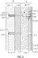
- FIG 3 it is shown an embodiment of a rigid construction (2) that corresponds to a wall or façade of a building.
- the building of this embodiment was previously thermally insulated by adding an insulation layer (2.2) for instance using a ETICs system.
- the building has a substrate (2.1) covered by an already existing insulation layer (2.2).
- the substrate (2.1) may not be visually accessible and the insulation layer (2.2) may show damaged regions due to the passage of time and inclement weather.
- the first step of "modifying" the thermal insulation of the existing thermal insulation requires dismantling the existing insulating layers by removing any fixing elements, and if the insulation layer (2.2) has been glued by removing the adhesive if possible, and a further set of step installing a new insulation arrangement.
- the method disclosed in the prior art allows just the replacement of an existing insulation assembly by another insulation assembly, but it does not allow the modification or improvement of an existing insulation by combining the existing insulation and the insulation element to be added.
- the removal of the existing insulation element may require a relevant effort that maybe even bigger than the time and effort required for the element to be added. Additionally, dismantling fixing elements such as screws increases the damage around the hole the screws is inserted deteriorating the substrate of the façade even more.
- the added insulation element (1) does not require the removal of any previously installed insulation layer (2.2) and makes use of the hidden substrate (2.1) located under the insulation layer (2.2) for fixing the insulation element (1) to be added.
- a construction hole (2.1.1) is drilled by perforating the insulation layer (2.2), if it exists.
- a plug (3.5) is inserted in the bore hole for receiving a fastening screw (3.1) of a spacer fastening means (3).
- the fastening screw (3.1) or a plurality of them are intended for fixing an insulation element (1) on the insulation layer (2.2).
- the construction hole (2.1.1) is drilled after positioning the insulation element (1) on the insulation layer (2.2) since the drill bit passing through the insulation element (1) generates a mounting hole (1.3), through the insulation layer (2.2) and the substrate (2.1) generating the construction hole (2.1.1) at the same time (in one working step), all the perforations being aligned.
- the added insulation element (1) comprises one or more insulation elements (1) and one or more spacer fastening means (3) for fixing the insulation element (1) to the substrate (2.1).
- the insulation element (1) comprises a distal insulating layer (1.1) and a proximal insulating layer (1.2) wherein the rigidity of the proximal insulating layer (1.2) is lower than the rigidity of the distal insulating layer (1.1).
- Each insulation element (1) is fixed to the substrate (2.1) by screwing the fastening screw (3.1) of the spacer fastening means (3) passing through the already generated perforations, mainly the mounting hole (1.3) in the insulation element (1) and the construction hole (2.1.1) in the substrate (2.1) of the rigid construction (2) by penetrating into and secured in the plug (3.5).
- the spacer fastening means (3) comprises a fastening screw (3.1) having a length long enough for extending from the plug (3.5) in the secure position to the outer surface of the insulation element (1) taking into account the extra thickness of the insulation layer (2.2) that is kept on the substrate (2.1).
- the spacer fastening means (3) comprise the fastening screw (3.1) and a hollow shank (3.2).
- This combination of screw (3.1) and hollow shank (3.2) shows a first end portion (3.3) provided by the fastening screw (3.1) that is intended for fixing the spacer fastening means (3) into the plug (3.5) when housed in the construction hole (2.1.1) of the substrate (2.1), and a second end portion (3.4) that is intended for fixing the insulation element (1) at the outer surface of the distal insulating layer (1.1).
- the hollow shank (3.2) is rotatable with respect to the fastening screw (3.1), but there is axial retention between both parts (3.1, 3.2).
- the hollow shank (3.2) comprises a helical thread (3.2.1) ended in a retainer disk (3.2.2).
- the fixation between the second end portion (3.4) and the outer insulating layer (1.1) is provided with a wide helical thread (3.2.1).
- This helical thread (3.2.1) is screwed into the distal insulating layer (1.1) using a tool (not shown in this figure) until the retainer disk (3.2.2) rests on the outer surface of the distal insulating layer (1.1).
- the tool is designed as rotating tool which is adjustable to two directions of rotation (rotating either clockwise or counterclockwise).
- the tool is equipped with protruding elements which are designed to engage with openings in the retainer disk (3.2.2) of the hollow shank (3.2).
- the size of the protruding elements of the tool and the openings in the retainer disk (3.2.2) of the hollow shank (3.2) are adjusted to each other to realize a fit between them such that the rotation is transferred from the tool to the openings in the retainer disk (3.2.2) of the hollow shank (3.2) and thus making the hollow shank (3.2) rotate.
- the head of the fastening screw (3.1) remains accessible from the outer surface of the distal insulating layer (1.1) and may be turned in one direction or the opposite direction generating an axial movement of the hollow shank (3.2) resulting in an axial adjustment of the distal insulating layer (1.1) allowing to obtain a completely aligned surface between adjacent insulating elements (1).
- the proximal insulating layer (1.2) of the insulation element (1) has a lower rigidity than the rigidity of the distal insulating layer (1.1) and the axial adjustment of the fastening screw (3.1) of the spacer fastening means (3) results in a compression of the inner insulating layer ensuring than the insulation element (1) keeps in touch with the insulation layer (2.2).
- the previously installed insulation layer (2.2) may also show a compression capability that increases the one provided by the proximal insulation layer (1.2).
- the retainer disks (3.2.2) of the hollow shank (3.2) and other irregularities of the surface of the outer surface of the distal insulating layer (1.1) are covered by a base coat (1.1.3), a reinforcing glass mesh and a finishing layer (1.1.2), wherein reinforcing glass mesh (1.1.1) is embedded between the base coat (1.1.3) and the finishing layer (1.1.2). Additionally, these covering layers improve the visual aspect of the thermal and acoustic insulating structure (4).
- the insulating layer (2.2) previously installed in the rigid construction (2) gets totally hidden after completing the inventive method of modifying the insulation of the insulated rigid construction (2) and, even if certain damages remain in the insulating layer (2.2), these imperfections contribute to the thermal and acoustic insulating properties of the whole arrangement by superimposing their properties to the properties of the added insulation element (1).
Abstract
The present invention relates to a method for modifying the insulation of an insulated rigid construction by providing an insulation element, fixing said insulation element on said insulated rigid construction by perforating holes in the insulated rigid construction and by fixing it with spacer fastening means. The present invention is also related to such an insulating structure for modifying the insulation of an insulated rigid construction.
Description
- The present invention relates to a method for modifying the insulation of an insulated rigid construction by providing an insulation element, fixing said insulation element on said insulated rigid construction by perforating holes in the insulated rigid construction and by fixing it with spacer fastening means.
- The present invention is also related to such an insulating structure for modifying the insulation of an insulated rigid construction.
- Old Building' façades lacking thermal and acoustic insulation may be thermally and acoustically insulated by applying insulating materials externally to its substrate. In that way, the use of External Thermal Insulation Composite Systems, generally known and called ETICS, is nowadays well established. ETICS may also be installed on the outside part of a roof.
- ETICS comprising insulation elements with layers of different rigidity have been described as advantageous, particularly those made of mineral wool or wood wool insulation.
- In these systems, a softer, more flexible layer is arranged closer to the structural element, referred to as the proximal layer. A harder, more rigid layer is located further away from the structural element, referred to as the distal insulating layer. Fastening devices are also known, which extend through the proximal and distal insulating layers in the insulation element and fix them firmly to the structural element.
- Among other advantages, in these configurations, the more rigid layer serves as resilient base for the rendering coating and it is able to withstand mechanical stresses applied to the insulation element. The softer layer reduces the weight of the insulation element, contributes to an improved thermal insulation capacity, and being more flexible, it is capable of adapting itself to contours and irregularities which might be present in the structural element.
- Often, in this type of systems, the surface of the structural element does not need to be prepared before the insulation elements are arranged on to it, such as by application of a rendering layer to smoothen and eliminate unevenness or irregularities.
- The application of binding agent, e.g. bonding mortar, for bonding the insulation elements to the structural element can be omitted by the use of this type of systems, and with it also the need of applying a primer for improving adhesion of the binding agent to the surface of the structural element. External insulation systems comprising multilayer insulation elements of this type, as well as spacer fastening devices to be used in these systems, are described in the patents and patent applications
EP 2215317 B1 ,EP 2216454 A2 ,WO 2014090707 A1 andEP 2666919 A2 . - In addition, most commonly used ETICS are made of an insulation layer (e.g. panels), a coating layer, a frame layer, a printing layer and a finishing coat in order to acquire a panel shape in most cases made of mineral wool or expanded polystyrene. Workers from this field of technique are making use of both of these insulating materials previously mentioned for their thermal performances.
- As known prior art, the patent document
EP 3 150 772 discloses a system comprising a structural element, an insulation element and a space fastening element for fixing the panel to the façade. - Specifically, the spacer fastening element is adapted for fixation of the insulation element to the structural element. The distance between the distal insulating element and the structural element is adjustable by acting on said spacer fastening element by choosing the length of the fastening device.
- Additionally, said spacer fastening element comprises a hollow shank preferably made of plastic and showing an inner cavity. The hollow shank is provided with a helical thread running as a helical band. The above-mentioned inner cavity of the hollow shank is made for receiving a metal fastening screw provided with means for fixation to the structural element, specifically a threaded tip.
- The hollow shank and the fastening screw are adapted to be locked relative to each other in the axial longitudinal direction of the fastening screw, while being freely rotatable relative to each other. The helical thread is configured to penetrate into the insolating layer with help of a specifically designed screwing tool that allows to rotate the hollow shank while keeping the fastening screw already engaged into the structural element. An embodiment of the described spacer fastening element will be used in embodiments of the present invention.
- ETICS are commonly known and used for decreasing heat losses of an insulated building, for increasing the effective interior area, for increasing durability of said façade, for his easy application without damaging the insulated building if it exists and for having a high variety of finishing appearances.
- A known downside of External Thermal Insulation Composite Systems (ETICS) is poor durability before environment exposure in addition to constant growing strictness of energy-saving and fire protection regulations for buildings. In those cases, the renovation of said ETICS is necessary.
- So far, renovations of the façade insulation often require a dismantling of the whole existing ETICS layer until the raw substrate is reached. Once cleaning the anterior ETICS layer is done, the installation of a new ETICS with greater insulation capacity may be established. New solutions are coming out in the market such as installing a new layer of improved properties.
- Even if this solution shows increased insulation properties compared to the former insulation the cost of dismantling the old and damaged insulation is very high. Both factors, a first dismantling step and the subsequent installation of the new ETICS, increase the costs of installing new insulation.
- Additionally, dismantling the old fixing means that are fixed to the façade, increases the damage in the substrate. As a result, the façade shows holes, plugs and regions around these elements with increased damages after manipulating the fixing element inserted in such holes.
- Therefore, there is a need in the art of an easy solution for modifying the thermal insulation of an insulated rigid construction, at low cost, and avoiding the damage of the construction.
- The invention disclosed herein is based on the surprising finding by the inventors for modifying the insulation of an insulated wall, façade or roof, based on adding a set of insulating panels fixed to the wall through the existing insulation elements. With this solution, it is not necessary to dismantle the existing insulation elements given that they do not prejudice the added system, and even they contribute to the mechanical and thermal properties of the added system.
- In a first inventive aspect, the present invention provides a method for modifying the insulation of an insulated rigid construction wherein the insulated rigid construction comprises a substrate and an insulation layer, the method comprising the steps of:
-
a) placing an insulation element on the insulated rigid construction, the insulation element comprising:
- a distal insulating layer, adapted to be distal to the insulated rigid construction in its operative position,
- a proximal insulating layer, adapted to be proximal to the rigid construction in its operative position, wherein the rigidity of the proximal insulating layer is lower than the rigidity of the distal insulating layer, and
- optionally at least one mounting hole passing through the insulation element;
- b) establishing at least one construction hole in the insulated rigid construction by perforating through the insulation element, either by using the at least one mounting hole in the insulation element, if any, or otherwise by drilling a mounting hole passing through the insulation element;
- c) aligning each construction hole with each corresponding mounting hole of the insulation element; and,
-
d) fixing the insulation element to the insulated rigid construction with at least one spacer fastening means, each spacer fastening means passing through the aligned holes of step c), wherein the spacer fastening means comprises:
- ∘ a fastening screw, wherein said fastening screw comprises a first end portion adapted to be fixed to the substrate of the insulated rigid construction and,
- ∘ a hollow shank, wherein said hollow shank comprises a second end portion adapted to be engaged to the distal insulating layer;
and wherein the fastening screw has an axial retention with the hollow shank. - The present invention provides, in this fist inventive aspect, a method intended to modify the insulation of an insulated rigid construction, such as a wall, façade or roof, by fixating an insulation element over the existing insulated rigid construction. Suitable rigid constructions in the context of the application include those made of concrete, hollow clay brick, solid clay brick, lightweight aggregate concrete and aerated autoclave concrete, among others.
- The term "insulated" in the expression "insulated rigid construction" refers to the existing insulation that is attached to the rigid construction before modifying said insulation. Said existing insulation of the rigid construction can be, for example, an insulating layer of an insulation material or an insulation element.
- The method of the invention can be particularly suitable for repairing an existing insulated rigid construction, for improving the insulation capacity of an insulated rigid construction or for improving the mechanical stability of an insulated structure.
- According to the method of the invention, the insulation element is fixed to the insulated rigid construction, without requiring any preparation or previous renovations of the insulated rigid construction. Additionally, the added insulation element increases the thermal and acoustic capacities of the finished insulated construction.
- Furthermore, independently of the insulated rigid construction state, the fixation of the insulation element ensures perfect stability of the resulting combination after modifying the insulation of an insulated rigid construction.
- Additionally, the present invention provides a lighter weight installation process by not adding any type of gluing layer. Finally, the claimed method provides a way of overcoming irregularities of the insulation existing on the insulated rigid construction, for instance portions of the existing insulation being damaged by the inclement weather, by covering it with an often improved, insulation element.
- The insulation element provided in step a) of the method of the invention optionally comprises at least one mounting hole passing through the insulation element. The mounting hole can be generated when manufacturing the insulation element. The mounting hole can be optionally generated when perforating the construction hole while keeping the insulation element in its operative position; that is, in a position being supported on the surface of the insulated rigid construction where the insulation element will be finally fixed. Advantageously, performing the mounting hole in the insulation element when perforating the insulated rigid construction passing through the insulation element provide the assurance of perfect alignment when introducing the spacer fastening means inside the insulated rigid construction and through the insulation element.
- According to step a), the insulation element is placed on the insulated rigid construction. Specifically, the insulation element is placed on the insulation layer of the insulated rigid construction. Preferably, the insulation element is placed in such a way that it covers the insulated rigid construction. Further, according to step c), each construction hole is aligned with each corresponding mounting hole of the insulation element.
- The term "corresponding mounting hole" refers to the mounting hole having such a position in the insulation element that allows it, in operative manner, to be aligned with a construction hole of the insulated rigid construction. Both holes, a construction hole, and its "corresponding mounting hole" result in a pair of holes having an aligned position when the insulation element is in its final position.
- The insulation element is fixed to the insulated rigid construction according to step d), by means of at least one spacer fastening means, wherein each spacer fastening means pass through two aligned holes, namely the mounting hole in the insulation element and the corresponding construction hole in the insulated rigid construction. Particularly, the at least one spacer fastening means, is introduced inside a previously made construction hole inside the insulated rigid construction passing through a mounting hole of the insulation element which ensures the alignment and correct installation of the insulation element. More particularly, and if any mounting hole has been previously perforated, the spacer fastening means is introduced inside the at least one construction hole perforated by drilling a new mounting hole passing through the insulation element.
- The spacer fastening means is meant to fix the insulation element to the insulated rigid construction. Said element is adapted to hold the substrate of the insulated rigid construction and the distal insulating layer at a predefined distance. The spacer fastening means has preferably an elongated shape delimited by the first and second end portions, and is introduced inside the substrate of the insulated rigid construction and through the entire thickness of the insulation element. Advantageously, the distance created by the two portions between the insulated rigid construction and the distal insulating layer is adjustable thanks to the adaptable length of the spacer fastening means. Alternatively, the dimensions of the spacer fastening means can be adjusted to the specific substrate, in order to anchor the insulation element through the existing insulation layer into the substrate of the insulated rigid construction.
- The spacer fastening means comprises a fastening screw and a hollow shank. The fastening screw comprises a first end portion adapted to be fixed to the substrate of the insulated rigid construction. The first end portion of the fastening screw is further adapted to pass through the insulation layer of the insulated rigid construction and to be fixed to the substrate of the rigid construction. Additionally, the hollow shank comprises a second end portion adapted to be engaged to the distal insulating layer.
- Advantageously, by passing the first end portion of the spacer fastening means through the insulation layer of the insulated rigid construction and fixing it to the substrate, the increased distance and force of the spacer fastening means provide more stability to the whole insulation installation. In addition, the fixation of the added insulation element is combined with the already present fixation from the first insulation layer improving the entire fixation system. Finally, it secures potentially damaged fixations from the first insulation layer by fixing the spacer fastening means directly to the substrate and passing through the already existing insulation layer.
- The fastening screw of the spacer fastening means is located inside an inner cavity designed in the hollow shank. The hollow shank is previously shaped with said cavity through its entire thickness to allow access from the exterior to the fastening screw. The fastening screw is made for receiving a screwing tool, and extends away from the cavity through an aperture in the hollow shank available in its end more proximal to the insulated structural element.
- The fastening screw has an axial retention with the hollow shank. Said axial retention is produced by locking the fastening screw head on the inside of the inner cavity of said hollow shank. According to a preferred embodiment of the invention, a first end portion of said fastening screw of the spacer fastening means is designed for engaging the inside of the insulated rigid construction with the distal insulating layer thanks to the second end portion of the hollow shank of the spacer fastening means.
- The hollow shank might further comprise a retainer disk for the insulation element, arranged at one of its ends, preferably at its end most distal to the first end portion, and with a diameter at least the size of the diameter of the thread or of the maximum major diameter of the helical thread. The retainer disk might furthermore comprise small indentations on its surface more proximal to the insulation element, so that during installation the retainer disk might cut into the insulation element and slightly penetrate into it.
- In a particular embodiment, the insulation layer of the insulated rigid construction is an External Thermal Insulation Composites System (ETIC system), preferably comprising mineral wool and/or foamed plastic. More preferably, the insulation layer of the insulated rigid construction is an ETIC system comprising glass wool, extruded polystyrene (XPS) and/or expanded polystyrene (EPS).
- According to this embodiment, when the existing ETIC system is kept, it provides increased thermal and acoustic characteristics to the rigid construction and the finished building with the layers provided by the added insulation element. These added layers may be even thinner because of the contribution of the existing ETICs.
- According to a particular embodiment, the distal insulating layer and/or the proximal insulating layer of the insulation element comprise mineral wool or foamed plastic. Preferably, the distal insulating layer and/or the proximal insulating layer of the insulation element comprises mineral wool, formed by glass, stone or slab fibers. In another embodiment, the distal insulating layer and/or the proximal insulating layer of the insulation element comprise glass wool.
- According to a particular embodiment, the distal insulating layer and/or the proximal insulating layer of the insulation element comprise mineral wool and foamed plastic.
- Preferably, the insulation element added in the method of the invention, is an ETIC system, more preferably comprising mineral wool, and/or foamed plastic. Even more preferably, the insulation element comprises glass wool, extruded polystyrene (XPS) and/or expanded polystyrene (EPS).
- Even more preferably, the insulation layer of the rigid construction and the insulation element provided in step a) are both ETIC systems. Preferably, they are both ETIC systems comprising mineral wool and/orfoamed plastic. More preferably, the insulation layer of the rigid construction and the insulation element provided in step a) are both ETIC systems comprising glass wool, extruded polystyrene (XPS) and/or expanded polystyrene (EPS).
- The insulation element provided in step a) comprises:
- a distal insulating layer, adapted to be distal to the rigid construction in its operative position,
- a proximal insulating layer, adapted to be proximal to the rigid construction in its operative position, wherein the rigidity of the proximal insulating layer is lower than the rigidity of the distal insulating layer, and
- optionally at least a mounting hole passing through the insulation element.
- The layer of the insulation element proximal to the insulated rigid construction, i.e.: the proximal insulating layer, is characterized by being less rigid and more flexible than the external layer. The proximal insulating layer has thus a lower resistance to compressive stress in its thickness direction than the distal insulating layer. Advantageously, the soft and flexible characteristics of the proximal insulating layer of the insulation element confer to the insulation element the ability to be compressed while fixated, and expand back to his most effective form once installed. In the context of the present invention, the "proximal insulating layer" is also named as "internal proximal insulating layer" or "inner insulating layer".
- Additionally, the proximal insulating layer reduces the weight of the insulation element and increases the covering capacity and adaptability of its shape to contours and irregularities which might be present in the surface of the insulated rigid construction (i.e. the non-modified insulated rigid construction), by deformation of the insulated element on the insulated rigid construction.
- The proximal insulating layer might be formed by a single layer of homogeneous composition, or it might also comprise several layers of different composition or properties. The proximal insulating layer may be formed by fibrous insulating material, preferably the proximal insulating layer is formed by fibrous insulating material and has an homogeneous composition and/or uniform properties.
- Preferably, the proximal insulating layer comprises fibrous insulating material with a density lower than the density of the distal insulating layer. The density of the proximal insulating layer suitably ranges from 10 - 60 kg/m3, preferably from 20 - 45 kg/m3 and more preferably from 25 - 35 kg/m3. More preferably, the proximal insulating layer does not comprise fibrous insulating material with a density equal or higher than 60 kg/m3.
- In the context of the present application, the density of the fibrous insulating material refers to the material as such, including the fiber network and any binder, additive, etc. it might have. The density is meant in the uncompressed and unpacked state. The artisan knows how to determine the density of fibrous insulating materials such as wood wool or mineral wool. Reference is made to the standard method UNE EN 823:2013 for measuring the thickness of thermal insulating products, from which density can be calculated from the length and width dimensions, and the weight of a fibrous material sample.
- According to the first aspect the rigidity of the proximal insulating layer is lower than the rigidity of the distal insulating layer. In the context of the present invention, the term "rigidity" refers to the stiffness of the material or its resistance to bending deformation under a load applied perpendicular to one of the larger surfaces of the insulating layer. The rigidity of the insulating layer may depend on the combination of multiple parameters such as the binder content, density and the fiber orientation in the insulating layer.
- The proximal insulating layer of the insulation elements may comprise fibrous insulating material with a laminar configuration of the fibers. In other words, the fibers forming the fibrous insulating material of the proximal insulating layer are predominantly oriented parallel to the larger surfaces of the fibrous insulating layer. Usually, the fibers having a laminar configuration have not been subjected to any process to enhance their orientation in the direction of the thickness of the proximal insulating layer. This preferred orientation of the fibers contributes to an enhanced thermal insulation capacity of the internal layer.
- The thermal conductivity of the proximal insulating layer, measured as lambda at 10°C according to UNE EN 12667:2002 is preferably lower than 0.045 W(K m)-1, preferably lower than 0.040 W(K m)-1, and more preferably in the range 0.030 - 0.038 W(K m)-1.
- Preferably, the proximal insulating layer comprises mineral wool, formed by glass, stone or slab fibers. More preferably, the proximal insulating layer comprises glass wool.
- In the embodiments where the proximal insulating layer comprises fibrous insulating material, this material is preferably bonded by a cured organic binder. The binder content of the fibrous insulating materials is defined as the "Loss of Ignition" or "LOI". The LOI values provided in the present application were all measured according to the norm ISO 29771:2008. The LOI of the fibrous insulating material of the proximal insulating layer in these embodiments is preferably lower than 12 wt.-% related to the total weight of the fibers, more preferably between 2 - 8 wt.-%, and even more preferably between 3 - 7 wt.-%. These levels of binder content results in improved flexibility, softness and adaptability of the proximal insulating layer.
- The proximal insulating layer and the distal insulating layer are distinct. In other words, both layers have different compositions and/or properties. The distal and proximal insulating layers are preferably manufactured separately from each other.
- Preferably, the proximal and distal insulating layers are laminated by being bonded to each other by an adhesive applied to their facing surfaces. The adhesives used might be reactive (one or two component) polyurethane, polyolefin hot-melt or other adhesives, applied by any suitable method known in the art. Alternatively, the proximal and distal insulating layers might be joined by application of a layer of thermoplastic film or non-woven (e.g. non-woven polyamide) between them, which is molten before the layers are contacted and cooled down after the joining to achieve their bonding.
- The distal insulating layer of the insulation element adapted to be distal to the insulated rigid construction, is located away from the insulated rigid construction, such as wall, façade or roof. Additionally, the distal insulating layer is the visible part of the finished product.
- The distal insulating layer is preferably made of a rigid material. The distal insulating layer of the insulation element has higher rigidity than the proximal insulating layer. The higher rigidity of the distal insulating layer turns into a better ability of this layer to resist deformation without fracture in response to applied forces in its thickness direction.
- In a particular embodiment, the distal insulating layer of the insulation element provided in step a), has a compressive stress at 10% deformation of at least 3 times higher than the proximal insulating layer, measured according to UNE EN 826:2013. Preferably, the distal insulating layer has a compressive stress at 10% deformation, of at least 4 times, higher than the compressive stress at 10% deformation of the proximal insulating layer. Also preferably, the distal insulating layer has a compressive stress at 10% deformation lower than 15 kPa or lower than 10 kPa, more preferably of 5 - 1 kPa. The compressive stress, although it represents only the resistance to compression forces, is a parameter for estimating the robustness, hardness and/or rigidity since it is directly proportional to any of these properties.
- The compressive stress at 10% deformation of the proximal insulating layer, measured according to UNE EN 826:2013, is preferably lower than 5 kPa, more preferably lower than 3 kPa and even more preferably lower than 2 kPa.
- Preferably, the density of the fibrous insulating material of the distal insulating layer ranges from 60 - 120 kg/m3, more preferably 70 - 100 kg/m3. In any embodiment, the distal insulating layer does not comprise fibrous insulating material with a density equal or higher than 140 kg/m3.
- The thickness of the distal insulating layer is preferably at least 15 mm, more preferably at least 25 mm.
- The fibrous insulating material in the distal insulating layer has preferably an homogeneous composition and/or uniform properties.
- The distal insulating layer of the insulation elements may comprise fibrous insulating material with a laminar configuration of the fibers. The fibers having a laminar configuration are predominantly oriented parallel to the larger surfaces of the distal insulating layer, namely, perpendicular to the thickness of the insulating layer. This preferred orientation of the fibers requires less manufacturing efforts and complexity and contributes to an enhanced thermal insulation capacity of the internal layer, when compared with fibrous insulating materials wherein the fibers have been oriented in the direction of the heat transfer.
- The thermal conductivity of the distal insulating layer, measured as lambda at 10°C according to UNE EN 12667:2002 is preferably lower than 0.040 W (K m)-1, preferably lower than 0.036 W (K m)-1, and more preferably in the range 0.036 - 0.030 W(K m)-1.
- In preferred embodiments, the fibrous insulating material of the distal insulating layer is bonded by a cured organic binder, suitably comprising a thermoset resin. The content of the organic binder in the fibrous insulating material of the external layer, measured as "Loss On Ignition" (LOI) is preferably higher than 5 wt.-% related to the total weight of the fibers, preferably between 6 -15 wt.-% and more preferably between 8 - 13 wt.%. These levels of binder content contribute to further enhance the mechanical properties, particularly the rigidity and compression resistance, of the distal insulating layer.
- The mean fiber diameter of the fibrous insulating material of the distal insulating layer may be suitably at least 4 micrometers and lower than 15 micrometers, preferably from 5 - 10 micrometers, as calculated from microscopy analysis. Fibrous insulating material with this fiber diameter range provides an enhanced rigidity to the distal insulating layer. In order to improve the rigidity of the distal insulating layer, it is preferably that the distal insulating layer comprises a reinforcing web on at least one of its two larger surfaces. More preferably, the reinforcing web is provided on both larger surfaces of the distal insulating layer. The reinforcing web acts as a distribution layer for loads applied to the insulation element during use of the wall, façade or roof system, such as those caused by wind suction or compression. Those loads are concentrated in the areas of the insulation element close to the fastening devices. The reinforcing web distributes this load through a larger area, thus, increasing the resistance of the insulation element against mechanical tensioning.
- The reinforcing web may be arranged on the larger surface of the distal insulating layer more proximal to the structural element. The presence of the reinforcing web on or at this surface facilitates the bonding of the proximal and distal insulating layers, by providing a more homogeneous and smoother bonding surface, which results in increased bonding strength and reduced adhesive or thermoplastic consumption.
- The reinforcing web can be any web of sufficient mechanical resistance to dimensional change. It is preferred that it has a porous open structure, more preferably a fabric or nonwoven structure of fibers. The reinforcing web is preferably a glass fiber textile or non-woven. Glass fiber veils made out of glass fibers laid down randomly and bonded with a binder have shown to be suitable. Reinforcing filaments might be incorporated into the web structure to increase dimensional stability. The thickness of the reinforcing web ranges preferably from 100 to 1000 micrometers, more preferably from 200 - 700 micrometers. The weight per surface area (grammage) of the reinforcing web preferably ranges from 20 to 150 g/m2, more preferably from 30 to 130 g/m2, even more preferably from 100 to 130 g/m2, even more preferably about 125 g/m2.
- This reinforcing web is preferably directly laminated to the insulating material by any conventional method. When the insulating material is a fibrous insulating material, it is preferred that the reinforcing web is bonded to the fibers by the same cured binder used for bonding the fibers of the fibrous insulating material. Particularly advantageous is the application of the reinforcing web to the fibrous material while it is in uncured state, during manufacturing, and the subsequent introduction of contacted fibrous insulating material and reinforcing web into a curing oven to produce their bonding by the cured binder.
- In a particular embodiment, step d) comprises introducing the first end portion of the fastening screw of the spacer fastening means with a depth of at least d = 50mm into the substrate of the insulated rigid construction.
- According to this embodiment, it has been proven that introducing the first end portion of the spacer fastening means at least d=50mm deep into the rigid construction results in a very stable axial fixation for the layers of the added insulation element being located over the already existing insulation layer. The added layers are understood as the proximal and the distal insulating layer according to the invention.
- Preferably, the hollow shank is made of plastic. Preferably, the fastening screw is made of metal.
- In a particular embodiment, the hollow shank of the spacer fastening means comprises a helical thread adapted to be engaged into the distal insulating layer.
- The hollow shank, located on the second end portion of the spacer fastening means, completely engages into the distal insulated layer of the insulated element and may partially engage into the proximal insulated layer closest to the distal insulating layer. In addition, the helically shaped thread facilitates the introduction of said hollow shank inside the insulation element by a rotational screwing movement.
- The diameter of the thread band is large enough to provide sufficient anchoring strength of the insulating material to the shank. In embodiments, the maximal diameter of the thread band is preferably at least 50 mm, and it might range from 50 - 100 mm, more preferably from 60 - 80 mm. Preferably, the helical thread has a conical shape, with increasing diameter going away from the insulated rigid construction. The conical shape facilitates the penetration of the thread in the fibrous insulating material. The helical thread might be formed as a continuous band or it might be formed by different separated thread sections. The parameters of the helical thread such as the pitch and the thread angle are adapted to facilitate the penetration by screwing movement into the distal insulating layer. The pitch of the helical thread, this is, the distance between two consecutive thread crests, is preferably constant. Preferably, the pitch is at least 3 mm, more preferably at least 4 mm, even more preferably at least 10 mm or at least 15 mm. The thread pitch preferably does not exceed 30 mm, and more preferably it does not exceed 20 mm, i.e. the most preferred range is from 10 to 20 mm.
- If the distal insulating layer of the insulation element comprises mineral fibers, said mineral fibers get inserted between thread crests, thereby enhancing the anchoring effect.
- Advantageously, and in a more preferred embodiment, the helical thread preferably extends through the whole thickness of the distal insulating layer. Optionally, the helical thread also extends partially into the proximal insulating layer of the insulation element. In alternative embodiments, the length of the thread is designed to be essentially the same as the thickness of the distal insulating layer, or slightly smaller.
- The distance between threads, more precisely between each spacer fastening means, is preferably constant and adequate in order to provide sufficient axial anchoring of the distal insulating layer to the hollow shank.
- In a particular embodiment, the distal insulating layer of the insulation element provided in step a), comprises mineral wool, wherein the fibers of the mineral wool are predominantly oriented perpendicular to the thickness of said distal insulating layer.
- The proximal insulating layer is softer than the distal insulating layer in order to endure compressive loads while fixating the insulation element and expand back to his most efficient thermal and acoustic insulation shape once all steps of the claimed method are completed.
- On the contrary, according to this embodiment, the distal insulating layer comprises mineral fibers predominantly oriented perpendicular to the thickness of the layer conferring a larger rigidity in the axial direction. When the helical thread of the hollow shank penetrates into the distal insulating layer the oriented fibers provide increased stability between the spacer fastening means and the distal construction resulting in a more resistant and rigid construction. Preferentially the mineral fibers contained in the distal insulating layer are glass fibers.
- Advantageously, the distal insulating layer is more rigid than the proximal insulating layer in order to resist multiple spacer fastening means introductions during the installation process. In addition, the resistance of the distal insulating layer also provides better manipulation.
- The distal outer insulating layer of the insulation element may be covered with a finishing layer in order to improve the resistance of said materials to weather conditions, protect and/or adapt the appearance of the finished wall, façade or roof with the preferred colored mortar, paint or similar. The addition of mortar prevents the exterior surface, being visually accessible, from showing irregularities generated for example by the hollow shank.
- In a particular embodiment, the method comprises the step e) of applying a base coat, a reinforcing glass mesh, and a finishing layer on the insulation element, wherein the base coat is applied on the external surface of the distal insulating layer, and wherein the reinforcing glass mesh is embedded between the base coat and the finishing layer.
- According to this specific embodiment, the external surface of the distal insulating layer is reinforced with a very resistant layer, the glass mesh, while keeping the flatness properties provided by the base coat and the finishing layer.
- The base coat may be a mortar coating that is applied to the external surface of the distal insulating layer. The base coat may also cover the spacer fastening device. The mesh may be incorporated embedded into the mortar layer. The reinforcing web can be any web of sufficient mechanical resistance to dimensional change. It is preferred that it has a porous open structure, more preferably a fabric or nonwoven structure of fibers.
- The reinforcing mesh is preferably a glass fiber textile or non-woven. Glass fiber veils made out of glass fibers laid down randomly and bonded with a binder have shown to be suitable. Reinforcing filaments might be incorporated into the web structure to increase dimensional stability. The thickness of the reinforcing web ranges preferably from 100 to 1000 micrometers, more preferably from 200 to 700 micrometers. The weight per surface area (grammage) preferably ranges from 20 to 150 g/m2, more preferably from 30 - 130 g/m2, even more preferably from 100 to 130 g/m2, even more preferably about 125 g/m2.
- Optionally the base coat is covered by additional layers to improve the weathering resistance, and/or the appearance, such as finishing colored mortars, paint and the like.
- In a second inventive aspect, the present invention provides an insulating structure for modifying the thermal insulation of an insulated rigid construction wherein the insulated rigid construction comprises a substrate, an insulation layer and at least a construction hole perforated in the insulated rigid construction, and the insulating structure comprises:
- an insulation element, comprising a distal insulating layer, adapted to be distal to the insulated rigid construction in its operative position, a proximal insulating layer, adapted to be proximal to the insulated rigid construction in its operative position, and at least one mounting hole passing through the insulation element and aligned with at least one corresponding construction hole of the insulated rigid construction, wherein the rigidity of the proximal insulating layer is lower than the rigidity of the distal insulating layer, and
- at least one spacer fastening means configured for fixing the insulation element to the insulated rigid construction, each spacer fastening means passing through the aligned mounting and construction holes of the insulation element and of the insulated rigid construction respectively, wherein the spacer fastening means comprises:
- ∘ a fastening screw, wherein said fastening screw comprises a first end portion that is fixed to the insulated rigid construction and,
- ∘ a hollow shank, wherein said hollow shank comprises a second end portion that is engaged to the distal insulating layer,
- The second aspect of the invention refers to the insulating structure for modifying the thermal insulation of an insulated rigid construction, and further installing an insulation element and at least one spacer fastening means configured for fixing the insulation element to the insulated rigid construction; therefore, passing through and keeping the already existing insulation of the insulated rigid construction. That is, the added insulating structure is mounted directly over the insulated rigid construction and eases the process of manipulation and installation while the properties of the previous insulation are advantageously maintained.
- The features of the elements disclosed above in the insulated structure resulting in a modified thermal insulation of an insulated rigid construction are those characterizing the disclosed embodiments of this second aspect of the invention.
- In a particular embodiment, the insulation layer of the insulated rigid construction is an ETIC system, preferably comprising mineral wool and/or foamed plastic. More preferably, the insulation rigid construction is an Etic system comprising glass wool, extruded polystyrene (XPS) and/or expanded polystyrene (EPS).
- In a particular embodiment, the distal insulating layer and/or the proximal insulating layer of the insulation element comprise mineral wool or foamed plastic. Preferably, the distal insulating layer and/or the proximal insulating layer of the insulation element comprises glass wool, extruded polystyrene (XPS) or expanded polystyrene (EPS). In a preferred embodiment, the distal insulating layer and/or the proximal insulating layer of the insulation element comprise glass wool.
- In another particular embodiment, the distal insulating layer and/or the proximal insulating layer of the insulation element comprise mineral wool and foamed plastic.
- In another embodiment, the distal insulating layer of the insulation element comprises mineral wool, and the fibers of the mineral wool are predominantly oriented perpendicular to the thickness of said distal insulating layer, that is in a laminar configuration. The laminar configuration of the fibers naturally results from the deposition of the fibers freshly formed by a series of fiberizers and attenuated by air streams from burners vertically onto a receiving foraminous conveyor, under air suction from beyond the conveyor. Additionally, stretching of the fibers in the manufacturing line leads to the laminar configuration of the fibers, wherein the fibers are predominantly oriented perpendicularly to the thickness of the insulating layer. Stretching of the fibers can be produced by increasing the velocity by which the mat passes between the foraminous conveyor and the curing oven conveyor.
- In the context of the present invention, a stretching ratio is defined as the ratio between the speed of the curing conveyor (Vcc) and the speed of the forming conveyor (Vfc); i.e. Vcc / Vfc. Particularly, the stretching ratio that leads to the laminar configuration of the fibers is comprised between 0.9-1.2, preferably 0.95-1.15 and more preferably between 1.0-1.1.
- The inventors have seen that when the stretching ratio is slightly below 1, that is between 0.90 and 0.99, fibers become slightly wavy, producing an improvement in the final product properties, such as flexibility, compressive strength, delamination strength and less bending strength. If the stretching ratio is 1 or slightly above 1, that is from 1 to 1.2, the fibers become stretched and, as a result, the stiffness increases, and lambda (thermal conductivity) improves. When the stretching ratio is higher than 1.2, the risk of mineral fibers breakage is very high, hindering the product manufacturing.
- In a further embodiment, the degree of stretching of the mat can be increased by running the conveyors at sequentially increased speeds downstream the manufacturing line. The following example might demonstrate this type of arrangement, a manufacturing line comprises 3 conveyors: A first conveyor (= forming conveyer; v1 = Vfc) is followed by a second conveyor; the second conveyor is operated with a higher speed than the speed of the first conveyor (v2/v1 = e.g. 1.05 to 1.2); the second conveyor is followed by a third conveyor, whereas the third conveyor is operated with a higher speed than the speed of the second conveyor (v3/v2 = e.g. 1.05 to 1.20); the third conveyor might be designed as curing conveyor (v3 = Vcc).
- In a further embodiment, additional conveyors are placed between the first conveyor (= forming conveyer) and the last conveyor (= curing conveyor) downstream the manufacturing line. Thus, in
total 4 or more conveyors can be arranged downstream the manufacturing line, whereas with respect two consecutive conveyors, each subsequent conveyor is operated at least with the same speed, but preferentially with a higher speed than the immediately preceding conveyor. - Optionally, the laminar configuration of the fibers, this is, the predominant orientation parallel to the major surfaces, can be further improved by compressing the mat in the thickness direction (= vertical compression) and/or by stretching the uncured mat, and then curing the binder.
- Unlike crimping processes or lamella formation, in the laminar configuration of the fibrous insulating material according the present invention, the fibers shall not have been subjected to any process to increase their orientation in the direction perpendicular to the major surfaces of the mat. Thus, the laminar configuration of the fibers requires less manufacturing efforts. Further, for the crimped configuration of the fibrous insulating material the "stretching" ratio-which should be actually understood as "bulging ratio" or "factor of horizontal compression" - is typically comprised between 0.3 and 0.5, being the velocity of the curing conveyor (Vcc) significantly lower than the velocity of the forming conveyor (Vfc).
- According to the present invention, the laminar configuration of the fibers increases the rigidity of the whole insulating structure and provides stability to the spacer fastening means fixed through both the distal insulating layer of the insulation element and the rigid construction. More specifically, the predominantly orientation of fibers, parallel to the larger surfaces of the insulating layer, increases the stability of the joint between the helical thread of the hollows shank and the distal insulating layer.
- Additionally, the laminar configuration of the fibers contributes to an enhanced thermal insulation capacity in comparison with insulating layers wherein the fibers are oriented in the direction of the heat transfer. In this sense, the thermal conductivity of the insulating layer, measured as lambda at 10°C according to UNE EN 12667:2002 is preferably lower than 0.045 W (K m)-1, more preferably lower than 0.036 W (K m)-1, and even more preferably in the range 0.036 - 0.030 W(K m)-1.]
- In another embodiment, the distal insulating layer of the insulation element has a compressive stress at 10% deformation, measured according to UNE EN 826:2013, of at least 3 times higher than the proximal insulating layer. Preferably, the distal insulating layer has a compressive stress at 10% deformation of at least 4 times, higher than the compressive stress at 10% deformation of the proximal insulating layer. Also preferably, the distal insulating layer has a compressive stress at 10% deformation lower than 15 kPa or lower than 10 kPa, more preferably of 1 - 5 kPa. In order to provide such values, specifically, both distal and proximal insulating layer materials are glass wool, extruded polystyrene (XPS) and/or expanded polystyrene (EPS), known materials for having compressive and deformation stress values. In a preferred embodiment, the distal insulating layer and/or the proximal insulating layer of the insulation element comprise glass wool. Specific rages of thickness for each of the layers according to a plurality of embodiments have been disclosed for the first aspect of the invention and also applies to this second aspect of the invention.
- In another embodiment, the hollow shank of the spacer fastening means of the insulation structure comprises a helical thread adapted to be inserted into the distal insulating layer.
- These and other features and advantages of the invention will be seen more clearly from the following detailed description of a preferred embodiment provided only by way of illustrative and non-limiting example in reference to the attached drawings.
- Figure 1
- This figure shows a sectional view of an insulated rigid construction as a wall or roof or façade of a building before modifying it according to an example.
- Figure 2
- This figure shows a sectional view of a spacer fastening means fixing the insulation element to the insulated rigid construction, according to an example.
- Figure 3
- This figure shows a sectional view of an insulating structure fixed to an insulated rigid construction, according to an embodiment of the invention.
- As will be appreciated by one skilled in the art, aspects of the present invention may be embodied as a method and as an insulating structure.
-
Figure 1 depicts a rigid construction (2) that corresponds to a wall or roof or façade of a building presenting a substrate (2.1) and an insulation layer (2.2). Said substrate (2.1) is a wall or façade of a building according to an example which previously needed thermal and/or acoustic insulation improvements. Consequently, an insulation layer (2.2), preferably an ETICs system made of mineral wool or glass wool, is covering the whole substrate (2.1) of the rigid construction (2). Over time and due to exposure of the insulation to inclement weather, this existing insulation is degraded or damaged. - In a preferred embodiment, said insulation layer (2.2) is an ETIC system, previously fixed to the substrate (2.1) using at least a spacer fastening means (3), (not shown in this figure) providing resistance, durability and secured fixation at determined locations of the insulation layer (2.2).
-
Figure 2 shows a spacer fastening means (3), used for the fixation of the insulating element according to the inventive method comprising a fastening screw (3.1), preferably made of metal, and a hollow shank (3.2), and preferably made of plastic. Said hollow shank (3.2) presents an inner cavity where the fastening screw (3.1) is housed. Said fastening screw (3.1), by means of a first end portion (3.3), is intended to reach the rigid construction (2) and to fix the insulation element (1) to said rigid construction (2). - The first end portion (3.3), which makes contact with the rigid construction (2), is housed in a plug (3.5) previously inserted into a bore hole in order to provide firm fixation of the spacer fastening means (3) inside said rigid construction (2).
- The second end portion (3.4), which makes contact with the insulation element (1), provides, due the shape of the hollow shank (3.2), advancement and insertion of the spacer fastening means (3) till reaching the optimal desired fixation between both, the insulation element (1) and the rigid construction (2).
- This fixation, according to the inventive method, is executed by screwing a helical thread (3.2.1) into the distal insulating layer (1.1) using a specific tool (not shown in
figure 2 ) engaged to an external retainer disk (3.2.2) of the hollow shank (3.2). The hollow shank (3.2) is rotationally linked to the fastening screw (3.1) allowing the helical thread (3.2.1) to be screwed into the distal insulating layer (1.1) while the fastening screw (3.1) remains fixed to the substrate (2.1). Once the hollow shank (3.2) has been fixed at least to the distal insulating layer (1.1) the head of the fastening screw (3.1) remains accessible in order to adjust the axial position of the whole spacer fastening means (3) since the fastening screw (3.1) and the hollow shank (3.2) are linked by axial retention. - Now, referring to
figure 3 , it is shown an embodiment of a rigid construction (2) that corresponds to a wall or façade of a building. The building of this embodiment was previously thermally insulated by adding an insulation layer (2.2) for instance using a ETICs system. As previously mentioned, the building has a substrate (2.1) covered by an already existing insulation layer (2.2). The substrate (2.1) may not be visually accessible and the insulation layer (2.2) may show damaged regions due to the passage of time and inclement weather. - According to the prior art, the first step of "modifying" the thermal insulation of the existing thermal insulation requires dismantling the existing insulating layers by removing any fixing elements, and if the insulation layer (2.2) has been glued by removing the adhesive if possible, and a further set of step installing a new insulation arrangement. Thus, the method disclosed in the prior art allows just the replacement of an existing insulation assembly by another insulation assembly, but it does not allow the modification or improvement of an existing insulation by combining the existing insulation and the insulation element to be added.
- The removal of the existing insulation element may require a relevant effort that maybe even bigger than the time and effort required for the element to be added. Additionally, dismantling fixing elements such as screws increases the damage around the hole the screws is inserted deteriorating the substrate of the façade even more.
- According to the invention, the added insulation element (1) does not require the removal of any previously installed insulation layer (2.2) and makes use of the hidden substrate (2.1) located under the insulation layer (2.2) for fixing the insulation element (1) to be added.
- According to an embodiment, in a first step, a construction hole (2.1.1) is drilled by perforating the insulation layer (2.2), if it exists. After drilling into the substrate (2.1) a plug (3.5) is inserted in the bore hole for receiving a fastening screw (3.1) of a spacer fastening means (3).
- The fastening screw (3.1) or a plurality of them are intended for fixing an insulation element (1) on the insulation layer (2.2).
- Preferably, the construction hole (2.1.1) is drilled after positioning the insulation element (1) on the insulation layer (2.2) since the drill bit passing through the insulation element (1) generates a mounting hole (1.3), through the insulation layer (2.2) and the substrate (2.1) generating the construction hole (2.1.1) at the same time (in one working step), all the perforations being aligned.
- The added insulation element (1) comprises one or more insulation elements (1) and one or more spacer fastening means (3) for fixing the insulation element (1) to the substrate (2.1).
- In this preferred embodiment, the insulation element (1) comprises a distal insulating layer (1.1) and a proximal insulating layer (1.2) wherein the rigidity of the proximal insulating layer (1.2) is lower than the rigidity of the distal insulating layer (1.1).
- Each insulation element (1) is fixed to the substrate (2.1) by screwing the fastening screw (3.1) of the spacer fastening means (3) passing through the already generated perforations, mainly the mounting hole (1.3) in the insulation element (1) and the construction hole (2.1.1) in the substrate (2.1) of the rigid construction (2) by penetrating into and secured in the plug (3.5).
- The spacer fastening means (3) comprises a fastening screw (3.1) having a length long enough for extending from the plug (3.5) in the secure position to the outer surface of the insulation element (1) taking into account the extra thickness of the insulation layer (2.2) that is kept on the substrate (2.1).
- The spacer fastening means (3) comprise the fastening screw (3.1) and a hollow shank (3.2). This combination of screw (3.1) and hollow shank (3.2) shows a first end portion (3.3) provided by the fastening screw (3.1) that is intended for fixing the spacer fastening means (3) into the plug (3.5) when housed in the construction hole (2.1.1) of the substrate (2.1), and a second end portion (3.4) that is intended for fixing the insulation element (1) at the outer surface of the distal insulating layer (1.1).
- The hollow shank (3.2) is rotatable with respect to the fastening screw (3.1), but there is axial retention between both parts (3.1, 3.2).
- The hollow shank (3.2) comprises a helical thread (3.2.1) ended in a retainer disk (3.2.2). The fixation between the second end portion (3.4) and the outer insulating layer (1.1) is provided with a wide helical thread (3.2.1). This helical thread (3.2.1) is screwed into the distal insulating layer (1.1) using a tool (not shown in this figure) until the retainer disk (3.2.2) rests on the outer surface of the distal insulating layer (1.1).
- The tool is designed as rotating tool which is adjustable to two directions of rotation (rotating either clockwise or counterclockwise). The tool is equipped with protruding elements which are designed to engage with openings in the retainer disk (3.2.2) of the hollow shank (3.2). The size of the protruding elements of the tool and the openings in the retainer disk (3.2.2) of the hollow shank (3.2) are adjusted to each other to realize a fit between them such that the rotation is transferred from the tool to the openings in the retainer disk (3.2.2) of the hollow shank (3.2) and thus making the hollow shank (3.2) rotate.
- The head of the fastening screw (3.1) remains accessible from the outer surface of the distal insulating layer (1.1) and may be turned in one direction or the opposite direction generating an axial movement of the hollow shank (3.2) resulting in an axial adjustment of the distal insulating layer (1.1) allowing to obtain a completely aligned surface between adjacent insulating elements (1).
- The proximal insulating layer (1.2) of the insulation element (1) has a lower rigidity than the rigidity of the distal insulating layer (1.1) and the axial adjustment of the fastening screw (3.1) of the spacer fastening means (3) results in a compression of the inner insulating layer ensuring than the insulation element (1) keeps in touch with the insulation layer (2.2).
- The previously installed insulation layer (2.2) may also show a compression capability that increases the one provided by the proximal insulation layer (1.2).
- After fixing the insulation element (1), the retainer disks (3.2.2) of the hollow shank (3.2) and other irregularities of the surface of the outer surface of the distal insulating layer (1.1) are covered by a base coat (1.1.3), a reinforcing glass mesh and a finishing layer (1.1.2), wherein reinforcing glass mesh (1.1.1) is embedded between the base coat (1.1.3) and the finishing layer (1.1.2). Additionally, these covering layers improve the visual aspect of the thermal and acoustic insulating structure (4).
- The insulating layer (2.2) previously installed in the rigid construction (2) gets totally hidden after completing the inventive method of modifying the insulation of the insulated rigid construction (2) and, even if certain damages remain in the insulating layer (2.2), these imperfections contribute to the thermal and acoustic insulating properties of the whole arrangement by superimposing their properties to the properties of the added insulation element (1).
and wherein the fastening screw has an axial retention with the hollow shank.
Claims (18)
- Method for modifying the insulation of an insulated rigid construction (2) wherein the insulated rigid construction (2) comprises a substrate (2.1) and an insulation layer (2.2), the method comprising the steps of:a) placing an insulation element (1) on the insulated rigid construction (2), the insulation element comprising:- a distal insulating layer (1.1), adapted to be distal to the insulated rigid construction (2) in its operative position,- a proximal insulating layer (1.2), adapted to be proximal to the rigid construction (2) in its operative position, wherein the rigidity of the proximal insulating layer (1.2) is lower than the rigidity of the distal insulating layer (1.1), and- optionally at least one mounting hole (1.3) passing through the insulation element (1);b) establishing at least one construction hole (2.1.1) in the insulated rigid construction (2) by perforating through the insulation element (1), either by using the at least one mounting hole (1.3) in the insulation element (1), if any, or otherwise by drilling a mounting hole (1.3) passing through the insulation element (1);c) aligning each construction hole (2.1.1) with each corresponding mounting hole (1.3) of the insulation element (1); and,d) fixing the insulation element (1) to the insulated rigid construction (2) with at least one spacer fastening means (3), each spacer fastening means (3) passing through the aligned holes of step c) (1.3, 2.1.1), wherein the spacer fastening means (3) comprises:∘ a fastening screw (3.1), wherein said fastening screw (3.1) comprises a first end portion (3.3) adapted to be fixed to the substrate (2.1) of the insulated rigid construction (2) and,∘ a hollow shank (3.2), wherein said hollow shank (3.2) comprises a second end portion (3.4) adapted to be engaged to the distal insulating layer (1.1);wherein the first end portion (3.3) of the fastening screw is further adapted to pass through the insulation layer (2.2) of the insulated rigid construction (2) and to be fixed to the substrate (2.1) of the rigid construction (2),
and wherein the fastening screw (3.1) has an axial retention with the hollow shank (3.2). - Method according to claim 1, wherein the insulation layer (2.2) of the rigid construction (2) is an ETIC system, preferably comprising mineral wool and/or foamed plastic.
- Method according to claim 1 or 2, wherein the distal insulating layer (1.1) and/or the proximal insulating layer (1.2) of the insulation element (1) comprise mineral wool or foamed plastic.
- Method according to any of the preceding claims, wherein the distal insulating layer (1.1) of the insulation element (1) comprises mineral wool, and wherein the fibers of the mineral wool are predominantly oriented perpendicular to the thickness of said distal insulating layer (1.1).
- Method according to claim 1 or 2, wherein the distal insulating layer (1.1) and/or the proximal insulating layer (1.2) of the insulation element (1) comprise glass wool.
- Method according to claims 1, 2, 4 or 5, wherein the distal insulating layer (1.1) and/or the proximal insulating layer (1.2) of the insulation element (1) comprise mineral wool and foamed plastic.
- Method according to any of the preceding claims, wherein the distal insulating layer (1.1) of the insulation element (1) has a compressive stress at 10% deformation of at least 3 times higher than the proximal insulating layer (1.2), measured according to UNE EN 826:2013.
- Method according to any of the preceding claims, wherein the hollow shank (3.2) of the spacer fastening means comprises a helical thread (3.2.1) adapted to be engaged into the distal insulating layer (1.1).
- Method according to any of the preceding claims wherein step d) comprises introducing the first end portion (3.3) of the fastening screw (3.1) of the spacer fastening means (3) with a depth of at least d = 50 mm into the substrate (2.1) of the insulated rigid construction (2).
- Method according to any of the preceding claims, further comprising the step e) of applying a base coat (1.1.3), a reinforcing glass mesh (1.1.1), and a finishing layer (1.1.2) on the insulation element (1), wherein the base coat (1.1.3) is applied on the external surface of the distal insulating layer (1.1), and wherein the reinforcing glass mesh (1.1.1) is embedded between the base coat (1.1.3) and the finishing layer (1.1.2).
- Insulating structure (4) for modifying the thermal insulation of an insulated rigid construction (2), wherein the insulated rigid construction (2) comprises a substrate (2.1) , an insulation layer (2.2), and at least a construction hole (2.1.1) perforated in the insulated rigid construction (2), and the insulating structure (4) comprises:- an insulation element (1), comprising a distal insulating layer (1.1), adapted to be distal to the rigid construction (2) in its operative position, a proximal insulating layer (1.2), adapted to be proximal to the insulated rigid construction (2) in its operative position, and at least one mounting hole (1.3) passing through the insulation element (1) and aligned with at least one corresponding construction hole (2.1.1) of the insulated rigid construction (2), wherein the rigidity of the proximal insulating layer (1.2) is lower than the rigidity of the distal insulating layer (1.1), and- at least one spacer fastening means (3) configured for fixing the insulation element (1) to the insulated rigid construction (2), each spacer fastening means passing through the aligned mounting and construction holes (1.3, 2.1.1) of the insulation element (1) and of the insulated rigid construction (2) respectively, wherein the spacer fastening means (3) comprises:- a fastening screw (3.1), wherein said fastening screw comprises a first end portion (3.3) that is fixed to the insulated rigid construction (2) and,- a hollow shank (3.2), wherein said hollow shank (3.2) comprises a second end portion (3.4) that is engaged to the distal insulating layer (1.1),wherein the first end portion (3.3) of the fastening screw (3.1) pass through the insulation layer (2.2) of the insulated rigid construction (2) and is fixed to the substrate (2.1) of the insulated rigid construction (2),
and wherein the fastening screw (3.1) has an axial retention with the hollow shank (3.2). - Insulating structure (4) according to claim 11, wherein the insulation layer (2.2) of the insulated rigid construction (2) is an ETIC system, preferably comprising mineral wool and/or foamed plastic.
- Insulating structure (4) according to claim 11 or 12, wherein the distal insulating layer (1.1) and/or the proximal insulating layer (1.2) of the insulation element (1) comprise mineral wool or foamed plastic.
- Insulating structure (4) according to any of claims 11 to 13, wherein the distal insulating layer (1.1) of the insulation element (1) comprises mineral wool, and wherein the fibers of the mineral wool are predominantly oriented perpendicular to the thickness of said distal insulating layer (1.1).
- Insulating structure (4) according to any of claims 11 to 14, wherein the distal insulating layer(1.1) and/or the proximal insulating layer (1.2) of the insulation element (1) comprise glass wool.
- Insulating structure (4) according to claim 11, 12, 14 or 15, wherein the distal insulating layer (1.1) and/or the proximal insulating layer (1.2) of the insulation element (1) comprise mineral wool and foamed plastic.
- Insulation structure according to any of claims 11 to 16, wherein the distal insulating layer (1.1) of the insulation element has a compressive stress at 10% deformation of at least 3 times higher than the proximal insulating layer, measured according to UNE EN 826:2013.
- Insulating structure according to any of claims 11 to 17, wherein the hollow shank (3.2) of the spacer fastening means (3) comprises a helical thread (3.2.1) adapted to be engaged into the distal insulating layer (1.1).
Priority Applications (1)
| Application Number | Priority Date | Filing Date | Title |
|---|---|---|---|
| EP20383036.9A EP4006247A1 (en) | 2020-11-30 | 2020-11-30 | Method for modifying the insulation of an insulated rigid construction |
Applications Claiming Priority (1)
| Application Number | Priority Date | Filing Date | Title |
|---|---|---|---|
| EP20383036.9A EP4006247A1 (en) | 2020-11-30 | 2020-11-30 | Method for modifying the insulation of an insulated rigid construction |
Publications (1)
| Publication Number | Publication Date |
|---|---|
| EP4006247A1 true EP4006247A1 (en) | 2022-06-01 |
Family
ID=73654765
Family Applications (1)
| Application Number | Title | Priority Date | Filing Date |
|---|---|---|---|
| EP20383036.9A Withdrawn EP4006247A1 (en) | 2020-11-30 | 2020-11-30 | Method for modifying the insulation of an insulated rigid construction |
Country Status (1)
| Country | Link |
|---|---|
| EP (1) | EP4006247A1 (en) |
Citations (9)
| Publication number | Priority date | Publication date | Assignee | Title |
|---|---|---|---|---|
| EP2216454A2 (en) | 2009-02-06 | 2010-08-11 | Unger-Diffutherm GmbH | Dampening system |
| DE102009059204A1 (en) * | 2009-12-18 | 2011-06-22 | Holzinger, Alois, Sen. | Method for increasing thickness of insulating material layer at building wall, involves forming layer with insulating material body on insulating material layer, and fastening insulating material body on building wall |
| EP2666919A2 (en) | 2012-05-22 | 2013-11-27 | RANIT-Befestigungssysteme GmbH | Method and mounting system for attaching insulation panels to a support surface |
| AT13599U1 (en) * | 2012-08-14 | 2014-04-15 | Egger Michael Mag | thermal insulation system |
| WO2014090707A1 (en) | 2012-12-10 | 2014-06-19 | Knauf Insulation | Insulation system |
| EP2215317B1 (en) | 2007-12-06 | 2015-03-11 | fischerwerke GmbH & Co. KG | Insulation holder and method for attaching an insulation plate |
| EP3150772A1 (en) | 2015-10-02 | 2017-04-05 | URSA Insulation, S.A. | Improved building wall or roof system comprising fibrous insulation |
| WO2017220057A1 (en) * | 2016-06-23 | 2017-12-28 | Fischer International S.R.O. | Combined system for mechanically fastening directly mounted thermal insulation panels |
| DE102017126056A1 (en) * | 2017-10-11 | 2019-04-11 | Fischerwerke Gmbh & Co. Kg | Method for fixing an insulating element and insulating dowels |
-
2020
- 2020-11-30 EP EP20383036.9A patent/EP4006247A1/en not_active Withdrawn
Patent Citations (9)
| Publication number | Priority date | Publication date | Assignee | Title |
|---|---|---|---|---|
| EP2215317B1 (en) | 2007-12-06 | 2015-03-11 | fischerwerke GmbH & Co. KG | Insulation holder and method for attaching an insulation plate |
| EP2216454A2 (en) | 2009-02-06 | 2010-08-11 | Unger-Diffutherm GmbH | Dampening system |
| DE102009059204A1 (en) * | 2009-12-18 | 2011-06-22 | Holzinger, Alois, Sen. | Method for increasing thickness of insulating material layer at building wall, involves forming layer with insulating material body on insulating material layer, and fastening insulating material body on building wall |
| EP2666919A2 (en) | 2012-05-22 | 2013-11-27 | RANIT-Befestigungssysteme GmbH | Method and mounting system for attaching insulation panels to a support surface |
| AT13599U1 (en) * | 2012-08-14 | 2014-04-15 | Egger Michael Mag | thermal insulation system |
| WO2014090707A1 (en) | 2012-12-10 | 2014-06-19 | Knauf Insulation | Insulation system |
| EP3150772A1 (en) | 2015-10-02 | 2017-04-05 | URSA Insulation, S.A. | Improved building wall or roof system comprising fibrous insulation |
| WO2017220057A1 (en) * | 2016-06-23 | 2017-12-28 | Fischer International S.R.O. | Combined system for mechanically fastening directly mounted thermal insulation panels |
| DE102017126056A1 (en) * | 2017-10-11 | 2019-04-11 | Fischerwerke Gmbh & Co. Kg | Method for fixing an insulating element and insulating dowels |
Similar Documents
| Publication | Publication Date | Title |
|---|---|---|
| EP3348725B1 (en) | Insulation system with insulating elements of glass wool and method for spaced fixation thereof | |
| EP2347059B1 (en) | Facade insulation system | |
| EP2839085B1 (en) | Insulation system for covering a façade of a building | |
| US20120073224A1 (en) | Composite cladding | |
| US8984830B2 (en) | Heat insulation element and a composite for insulating a building façade | |
| EP3150772B1 (en) | Improved building wall or roof system comprising fibrous insulation | |
| US20040033123A1 (en) | Method for fixing insulating boards and corresponding dowel | |
| EP4006247A1 (en) | Method for modifying the insulation of an insulated rigid construction | |
| EP3150773B1 (en) | Improved method for fixation of an insulation element to a structural element of a building, and spacer fastening device suitable for use in such a method | |
| EP4006246A1 (en) | Insulating structure and method for manufacturing such an insulating structure | |
| EP4134230A1 (en) | Insulation panel | |
| EA040883B1 (en) | METHOD FOR FASTENING INSULATION ELEMENT TO BUILDING STRUCTURAL ELEMENT | |
| JP2001123638A (en) | External wall modification structure | |
| EA045035B1 (en) | SEPARATION FASTENING DEVICE FOR FASTENING AN INSULATING ELEMENT TO A STRUCTURAL ELEMENT OF A BUILDING | |
| JP2001098740A (en) | Outer wall correction structure | |
| IE85979B1 (en) | A composite panel |
Legal Events
| Date | Code | Title | Description |
|---|---|---|---|
| PUAI | Public reference made under article 153(3) epc to a published international application that has entered the european phase |
Free format text: ORIGINAL CODE: 0009012 |
|
| STAA | Information on the status of an ep patent application or granted ep patent |
Free format text: STATUS: THE APPLICATION HAS BEEN PUBLISHED |
|
| AK | Designated contracting states |
Kind code of ref document: A1 Designated state(s): AL AT BE BG CH CY CZ DE DK EE ES FI FR GB GR HR HU IE IS IT LI LT LU LV MC MK MT NL NO PL PT RO RS SE SI SK SM TR |
|
| STAA | Information on the status of an ep patent application or granted ep patent |
Free format text: STATUS: THE APPLICATION IS DEEMED TO BE WITHDRAWN |
|
| 18D | Application deemed to be withdrawn |
Effective date: 20221202 |