EP2666738B1 - Dispositif pour trier des objets - Google Patents
Dispositif pour trier des objets Download PDFInfo
- Publication number
- EP2666738B1 EP2666738B1 EP20120168616 EP12168616A EP2666738B1 EP 2666738 B1 EP2666738 B1 EP 2666738B1 EP 20120168616 EP20120168616 EP 20120168616 EP 12168616 A EP12168616 A EP 12168616A EP 2666738 B1 EP2666738 B1 EP 2666738B1
- Authority
- EP
- European Patent Office
- Prior art keywords
- deflecting element
- deflecting
- adjustment means
- stage linear
- conveying belt
- Prior art date
- Legal status (The legal status is an assumption and is not a legal conclusion. Google has not performed a legal analysis and makes no representation as to the accuracy of the status listed.)
- Not-in-force
Links
- 238000007599 discharging Methods 0.000 claims description 6
- 230000001154 acute effect Effects 0.000 claims description 3
- 230000001960 triggered effect Effects 0.000 claims description 2
- 230000007935 neutral effect Effects 0.000 description 2
- 230000005540 biological transmission Effects 0.000 description 1
- 239000013590 bulk material Substances 0.000 description 1
- 239000012530 fluid Substances 0.000 description 1
- 239000000446 fuel Substances 0.000 description 1
Images


Classifications
-
- B—PERFORMING OPERATIONS; TRANSPORTING
- B65—CONVEYING; PACKING; STORING; HANDLING THIN OR FILAMENTARY MATERIAL
- B65G—TRANSPORT OR STORAGE DEVICES, e.g. CONVEYORS FOR LOADING OR TIPPING, SHOP CONVEYOR SYSTEMS OR PNEUMATIC TUBE CONVEYORS
- B65G47/00—Article or material-handling devices associated with conveyors; Methods employing such devices
- B65G47/74—Feeding, transfer, or discharging devices of particular kinds or types
- B65G47/76—Fixed or adjustable ploughs or transverse scrapers
- B65G47/766—Adjustable ploughs or transverse scrapers
Definitions
- the invention relates to a device for sorting items conveyed on a conveyor belt with a deflection element pivotally mounted about a rotation axis extending perpendicularly to the conveyor belt, to which an actuator can be acted upon, so that the object firstly pivots in a first pivoting position of the deflection element in which the Deflection element extending in the transport direction of the conveyor belt, on a conveyor track of the conveyor belt in the transport direction can be further promoted, on the other hand and in a second pivot position of the deflection, in which the deflection extends at an acute angle to the transport direction of the conveyor belt, laterally derived from the conveyor track of the conveyor belt is.
- a device for sorting conveyed on a conveyor belt objects which has a pivotable about a perpendicular to the conveyor belt arranged deflecting element. If the deflecting element is in a neutral first pivoting position, objects conveyed on the conveyor belt are transported on a conveyor track in the transport direction of the conveyor belt. If the deflection element is moved by means of an actuator in a lateral second pivot position, the objects are deflected in a corresponding direction left or right of the conveyor belt, so that they leave the conveyor track.
- the known device allows a lateral discharge of the articles in two opposite directions with respect to the conveyor belt or the conveyor track.
- the deflecting element is pivotally mounted about an axis of rotation extending centrally between two opposite side edges of the conveyor belt and has two opposite upright side walls whose spacing is greater than the transverse extent of the conveyed objects.
- the removal of the objects thus takes place by means of one of the two side walls of the deflecting element in dependence on the discharge direction.
- a stepper motor or coupled via a transmission with the axis of rotation DC motor is provided in a region above the deflecting element.
- US 3,543,916 describes a device for discharging in particular bulk material from a conveyor trough.
- a deflection plate is moved over a conventional piston-cylinder arrangement.
- the linear movement of the piston is carried out by appropriate valve circuits and use of fluid fuels.
- Object of the present invention is therefore to develop a device for sorting conveyed on a conveyor belt objects such that with little effort a safe and reliable removal of objects from a conveyor track is guaranteed.
- the invention in conjunction with the preamble of claim 1, characterized in that the axis of rotation in the region of a side edge of the conveyor track and / or the conveyor belt runs and that the actuator is designed as at least a two-stage linear actuator, which via a lever mechanism with the rotational axis of the deflection element is coupled, and that the two-stage linear actuator (10, 10 ') by two in the transport direction arranged one behind the other and coupled to each other pull magnet (16, 17) is formed.
- the invention provides a two-stage linear actuator, which acts on a deflecting element via a lever mechanism so that the deflecting element can assume two pivoting positions.
- a two-stage linear actuator which acts on a deflecting element via a lever mechanism so that the deflecting element can assume two pivoting positions.
- the two-stage linear actuator is pivotally connected at a first end thereof via an adjusting bolt with a transverse arm of the deflecting element.
- a lever mechanism is formed, which allows a simple way of converting the linear movement of the two-stage linear actuator in a pivoting movement of the deflecting element.
- the deflecting element is designed as a deflecting flap with an upright narrow side along which the axis of rotation runs.
- the deflection element thus extends in a direction perpendicular to the conveyor track or to the conveyor belt extending plane, which allows a simple and space-saving design of the device for deflection in a predetermined discharge direction.
- the axis of rotation associated narrow side of the deflecting element is arranged on a front in the transport direction arranged front of the deflecting element.
- the two tension magnets have no return springs for moving the tension magnets into an initial position. Instead, the tension magnets are moved by driving the other tension magnet in the starting position. By selectively driving one of the two tension magnets, the deflection element is moved to a defined first or second pivot position.
- a first deflecting element and a second deflecting element can be arranged upright on opposite longitudinal sides of the supporting frame or the conveyor track, so that the articles conveyed sequentially not only in the transport direction but in a first discharge direction to the left and in a second discharge direction can be deflected to the right.
- only one of the two deflecting elements is pivoted into the conveyor track in order to discharge the relevant object in the desired manner.
- the other deflecting element remains in the starting position parallel to the transport direction.
- the deflection of the object is thus carried out by triggering or triggering only a single deflecting element, namely, of that which faces in the starting position along the longitudinal side of the support frame or the conveying path of the discharge direction, to which the object is to be discharged laterally.
- the deflection is made compact.
- the deflection module comprises only a single deflection element and the associated two-stage linear actuator.
- the article is deflected in the first discharge direction or in the second discharge direction.
- This variant of the invention is particularly suitable if during the sorting a deflection should be provided only in a single discharge direction. The invention thus enables a flexible and needs-based arrangement of deflection modules.
- a device for sorting articles conveyed on a conveyor belt 1 can preferably be used for sorting containers or containers (bottles, cans, etc.) which are to be supplied to different receptacles on the side of the conveyor belt 1 for sorting in distinct manner.
- a deflecting module 3 arranged in the transporting direction 2 is provided, which is provided at predetermined positions Make a conveyor belt 1 carrying bar 4, for example, by screwing fastened.
- the deflection module 3 has a support frame 5, the upright and in the transport direction 2 extending first longitudinal side 6 and an opposite second longitudinal side 6 'are fixed to the bar 4.
- a deflection element 7 is pivotally mounted on the transport frame 5 so as to be pivotable about a rotation axis D extending perpendicular to the transport direction 2 and perpendicular to the conveyor belt 1.
- the axis of rotation D extends at a front side 8 of the deflection module 3 arranged in the transport direction 2 at the front.
- the two-stage linear actuator 10 has an adjusting bolt 12, which is in and out in the transport direction 2 and is coupled via a lever mechanism 13 with the axis of rotation D of the deflection element 7.
- the deflection element 7 has a transverse arm 14 on, on which the arranged at a first end 15 of the two-stage linear actuator 10 adjusting bolt 12 is articulated.
- the two-stage linear actuator 10 has a first tension magnet 16 and a second tension magnet 17 spaced apart in the transport direction 2 and which can be triggered and / or actuated in the opposite direction.
- the actuatable via a magnet 18 pull magnet 16, 17 are fixedly coupled together.
- a provision of the first tension magnet 16 and the second tension magnet 17 is effected by triggering the second tension magnet 17 and the first tension magnet 16.
- a return spring effecting the restoring force does not have the tension magnets 16, 17.
- the deflection element 7 in the neutral the object not deflecting first pivot position according to FIG. 2 located, seen in the transport direction 2 rear second pull magnet 17 is actuated or actuated, so that the adjusting bolt 12 is moved counter to the transport direction 2 and the deflecting element 7 assumes a parallel to the transport direction 2 position.
- the first pull magnet 16 is actuated so that the adjusting bolt 12 is extended in the transport direction 2 and the transverse arm 14, the deflecting element 7 spends in a direction not parallel to the transport direction 2.
- the conveyor track 11 tapers in the transport direction 2, so that the objects in the second pivoting position of the deflecting element 7 are deflected to the side in the first discharge direction A1.
- the axis of rotation D is arranged on a viewed in the transport direction 2 Front 8 of the support frame 5 and the deflecting element 7, the abutment of the article against the deflecting element 7 causes an increased impact force, which favors the deflecting element 7 in the second pivot position.
- the support frame 5 has on the second longitudinal side 6 'a stop 19, against which abuts the free end of the deflecting element 7 in the second pivot position.
- the deflecting element 7 is designed as a deflecting flap which runs in a vertical plane and at whose front narrow side 20, viewed in the transporting direction 2, runs the axis of rotation D.
- deflection module 3 has only a single deflecting element 7, which is arranged for deflecting the objects in the first discharge direction A1 on a seen in the transport direction 2 left side of the support frame 5.
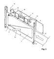
- a support frame 5 ' can also be designed so that a deflecting element 7' and a two-stage linear actuator 10 assigned to it are arranged facing away from the first ejection direction A1 second ejection direction A2, namely in the region of the second longitudinal side. 6 'of the support frame 5', see FIGS. 4 and 5 ,
- the support frame 5 'and the deflecting element 7' are arranged mirror-inverted with respect to a vertical center plane of the conveyor track 11 or conveyor belt 1 to the support frame 5 and deflection element 7.
- the two-stage linear actuator 10 ' is identical to the linear actuator of the first embodiment, that is, laterally offset from the two-stage linear actuator 10 in the region of the second longitudinal side 6 'of the support frame 5'.
- the free end of the deflecting element 7' strikes against a stop 19 'of the supporting frame 5' which, unlike the supporting frame 5, is not located on the second longitudinal side 6 'but on the first longitudinal side 6 ,
- the adjusting bolt 12 Upon actuation of the first pull magnet 16, the adjusting bolt 12 extends in the transport direction 2 and causes the pivoting of the deflecting element 7 'until it comes to rest against the stop 19'. Objects can now be deflected to the side along the second discharge direction A2. If the second pull magnet 17 is actuated, the adjusting pin 12 moves counter to the transport direction 2, so that the deflecting element 7 'is moved into the pivoting position parallel to the transport direction 2 and the articles can be conveyed further in the transport direction 2.
- a deflection module may be provided, that both the first deflection element 7 and the second deflection element 7 'and the associated two-stage linear actuators 10, 10' has.
- the two-stage linear actuators 10, 10 ' can preferably be arranged laterally offset from one another transversely to the transport direction 2. This advantageously forms a compact deflection module 3, which by selectively controlling the deflection element 7 or 7 'allows a discharge of the objects in the first discharge direction A1 or in the second discharge direction A2.
- the axis of rotation D is upright in the region of a side edge 21 or 21 'of the conveyor belt 1 or the conveyor track 11, so that a safe deflection of the objects in the first Ausschleuscardi A1 or the second discharge direction A2 is given.
- the conveyor belt 1 coincides with the conveyor track 11.
- a relatively wide conveyor belt may be provided so that a plurality of parallel conveyor tracks are formed along which several rows of articles can be conveyed simultaneously in the transport direction 2 are.
- the deflection elements 7 can be used not only for deflection in the side of the conveyor belt arranged container, but also for changing the conveyor track.
- the axes of rotation D do not have to be on a side edge 21, 21 'of the conveyor belt 1.
- At least two in the transport direction 2 spaced apart deflecting modules 3 may be provided, each having a first deflecting element 7 and the same associated two-stage linear actuator 10 and / or the second deflecting element 7 'and the same associated two-stage linear actuator 10th ', so that sequentially conveyed objects are selectively deflected in the first Ausschleus therapies A1 and / or the second Ausschleus therapies A2.
Landscapes
- Engineering & Computer Science (AREA)
- Mechanical Engineering (AREA)
- Discharge Of Articles From Conveyors (AREA)
Claims (10)
- Dispositif pour trier des objets transportés sur une bande transporteuse, comprenant un élément de déviation pouvant pivoter autour d'un axe de rotation s'étendant perpendiculairement à la bande transporteuse, sur lequel élément de déviation peut agir un organe de réglage, de telle sorte que l'objet puisse d'une part, dans une première position de pivotement de l'élément de déviation dans laquelle l'élément de déviation s'étend dans la direction de transport de la bande transporteuse, être transporté plus loin dans la direction de transport sur une voie de transport de la bande transporteuse, et puisse d'autre part, dans une deuxième position de pivotement de l'élément de déviation dans laquelle l'élément de déviation s'étend suivant un angle aigu par rapport à la direction de transport de la bande transporteuse, être évacué latéralement de la voie de transport de la bande transporteuse, caractérisé
en ce que l'axe de rotation (D) s'étend dans la région d'un bord latéral de la voie de transport (11) et/ou de la bande transporteuse (1) et en ce que l'organe de réglage (10, 10') est réalisé sous la forme d'au moins un organe de réglage linéaire à deux étages qui est accouplé à l'axe de rotation (D) de l'élément de déviation (7, 7') par le biais d'un mécanisme à levier (13) et
en ce que l'organe de réglage linéaire à deux étages (10, 10') est formé par deux électroaimants d'attraction (16, 17) disposés l'un derrière l'autre dans la direction de transport et accouplés l'un à l'autre. - Dispositif selon la revendication 1, caractérisé en ce que le mécanisme à levier (13) comprend un bras transversal en porte-à-faux (14) relié de manière solidaire en rotation à l'élément de déviation (7, 7'), sur lequel bras transversal en porte-à-faux agit l'organe de réglage linéaire à deux étages (10, 10') de telle sorte que l'élément de déviation (7, 7') puisse être amené exclusivement à la première position de pivotement ou à la deuxième position de pivotement.
- Dispositif selon la revendication 1 ou 2, caractérisé en ce que, pour former le mécanisme à levier (13), l'organe de réglage linéaire à deux étages (10, 10') est monté sur le bras transversal en porte-à-faux (14) de l'élément de déviation (7, 7') de manière articulée par le biais d'un boulon de réglage (12) disposé de manière mobile dans la direction de transport (2).
- Dispositif selon l'une quelconque des revendications 1 à 3, caractérisé en ce que l'élément de déviation (7, 7') est réalisé sous la forme d'un clapet de déviation présentant un côté étroit (20) vertical sur lequel s'étend l'axe de rotation (D).
- Dispositif selon l'une quelconque des revendications 1 à 4, caractérisé en ce que le côté étroit (20) recevant l'axe de rotation (D) de l'élément de déviation (7, 7') forme un côté avant, disposé à l'avant dans la direction de transport (2), de l'élément de déviation (7, 7').
- Dispositif selon la revendication 1, caractérisé en ce que les deux électroaimants d'attraction (16, 17) sont disposés de telle sorte qu'ils puissent être déclenchés et/ou actionnés en sens inverses.
- Dispositif selon la revendication 1 ou 6, caractérisé en ce que les électroaimants d'attraction (16, 17) peuvent être commandés en alternance pour faire passer le boulon de réglage (12) à une position avant dans la direction de transport (2), de telle sorte que l'élément de déviation (7, 7') se trouve dans la deuxième position de pivotement, ou à une deuxième position dans laquelle l'élément de déviation (7, 7') se trouve dans la première position de pivotement.
- Dispositif selon l'une quelconque des revendications 1 à 7, caractérisé en ce que l'organe de réglage linéaire à deux étages (10, 10') est disposé dans la région d'un côté supérieur (9) d'un cadre de support (5, 5') et l'élément de déviation (7, 7') est disposé dans la région d'un côté longitudinal (6, 6') du cadre de support (5, 5').
- Dispositif selon la revendication 8, caractérisé en ce que le cadre de support (5, 5') forme, conjointement avec le premier élément de déviation (7) disposé sur un premier côté longitudinal (6) de celui-ci ainsi qu'avec l'organe de réglage linéaire à deux étages (10) associé audit élément de déviation et/ou avec le deuxième élément de déviation (7') disposé sur un deuxième côté longitudinal (6') du cadre de support (5, 5') ainsi qu'avec l'organe de réglage linéaire à deux étages (10') associé audit élément de déviation, un module de déviation (3) pour la déviation de l'objet dans une première direction d'évacuation (A1) et/ou dans une deuxième direction d'évacuation (A2).
- Dispositif selon la revendication 9, caractérisé en ce qu'au moins deux modules de déviation (3) sont disposés de manière espacée les uns des autres dans la direction de transport (2), lesquels comprennent respectivement le premier élément de déviation (7) et l'organe de réglage linéaire à deux étages (10) associé à celui-ci et/ou le deuxième élément de déviation (7') et l'organe de réglage linéaire à deux étages (10') associé à celui-ci pour la déviation de manière sélective de l'objet dans la première direction d'évacuation (A1) et/ou dans la deuxième direction d'évacuation (A2).
Priority Applications (2)
| Application Number | Priority Date | Filing Date | Title |
|---|---|---|---|
| EP20120168616 EP2666738B1 (fr) | 2012-05-21 | 2012-05-21 | Dispositif pour trier des objets |
| DK12168616T DK2666738T3 (en) | 2012-05-21 | 2012-05-21 | Appliance for sorting objects |
Applications Claiming Priority (1)
| Application Number | Priority Date | Filing Date | Title |
|---|---|---|---|
| EP20120168616 EP2666738B1 (fr) | 2012-05-21 | 2012-05-21 | Dispositif pour trier des objets |
Publications (2)
| Publication Number | Publication Date |
|---|---|
| EP2666738A1 EP2666738A1 (fr) | 2013-11-27 |
| EP2666738B1 true EP2666738B1 (fr) | 2014-09-17 |
Family
ID=46146728
Family Applications (1)
| Application Number | Title | Priority Date | Filing Date |
|---|---|---|---|
| EP20120168616 Not-in-force EP2666738B1 (fr) | 2012-05-21 | 2012-05-21 | Dispositif pour trier des objets |
Country Status (2)
| Country | Link |
|---|---|
| EP (1) | EP2666738B1 (fr) |
| DK (1) | DK2666738T3 (fr) |
Families Citing this family (1)
| Publication number | Priority date | Publication date | Assignee | Title |
|---|---|---|---|---|
| DE102018109637A1 (de) * | 2018-04-23 | 2019-10-24 | Krones Ag | Vorrichtung und Verfahren zum Transportieren von Gebinden |
Family Cites Families (7)
| Publication number | Priority date | Publication date | Assignee | Title |
|---|---|---|---|---|
| US3543916A (en) * | 1968-09-13 | 1970-12-01 | Westinghouse Air Brake Co | Flow diverting shaker conveyor trough |
| US4643291A (en) * | 1986-01-21 | 1987-02-17 | Rexnord Inc. | Linear articulated pusher |
| DE60115224T2 (de) | 2000-03-31 | 2006-08-10 | Tomra Systems A/S | Vorrichtung zum fördern, heben und sortieren von gegenständen |
| US6615972B2 (en) * | 2000-04-27 | 2003-09-09 | Rapistan Systems Advertising Corp. | Sortation system diverter switch |
| DE10354777B4 (de) * | 2003-11-21 | 2008-03-27 | Sult Gmbh | Sortiereinrichtung zum Sortieren von unterschiedlichen Stoffen |
| US7147097B2 (en) * | 2004-09-30 | 2006-12-12 | Laitram, L.L.C. | Transverse-roller-belt sorter with automated guide |
| US20100006393A1 (en) * | 2008-07-14 | 2010-01-14 | Jervis B. Webb Company | Diverter Assembly |
-
2012
- 2012-05-21 DK DK12168616T patent/DK2666738T3/en active
- 2012-05-21 EP EP20120168616 patent/EP2666738B1/fr not_active Not-in-force
Also Published As
| Publication number | Publication date |
|---|---|
| DK2666738T3 (en) | 2014-12-08 |
| EP2666738A1 (fr) | 2013-11-27 |
Similar Documents
| Publication | Publication Date | Title |
|---|---|---|
| DE60118948T2 (de) | Überführung von gegenständen zwischen entgegengesetzt angetriebenen förderern | |
| EP1474348B1 (fr) | Dispositif de transport | |
| EP3072834B1 (fr) | Dispositif de transport muni d'un peigne de transport | |
| WO2004089790A1 (fr) | Dispositif pour modifier le sens de transport d'envois plats et la position de ces envois par rapport a leur sens de transport | |
| DE102011109967A1 (de) | Greifersystem | |
| DE102008047279A1 (de) | Vorrichtung zum Sortieren von Behältern | |
| EP3433189A1 (fr) | Appareil de préhension et dispositif de transport pour transporter des récipients | |
| DE10301178B4 (de) | Vorrichtung zum Ausrichten und Verteilen | |
| EP0372314A1 (fr) | Dispositif pour le retournement d'un emballage | |
| DE2943516A1 (de) | Foerdereinrichtung mit abkippbaren traegern | |
| DE2014915B2 (de) | Schleppkettenkreisförderanlage | |
| DE2552360C2 (de) | Werkstückelevator | |
| DE102021209986A1 (de) | Handhabungssystem zur automatischen Übergabe und Vereinzelung von Ladungsträgern | |
| DE102009040604A1 (de) | Vorrichtung zum Ausleiten von Transportgütern | |
| WO2008012214A1 (fr) | Distributeur pour articles | |
| EP2666738B1 (fr) | Dispositif pour trier des objets | |
| EP1352858A2 (fr) | Dispositif de triage avec porte-charges basculantes | |
| DE19681062C1 (de) | Fördereinrichtung | |
| EP1717179B1 (fr) | Dispositif pour stabiliser des produits imprimés transportés en flux le long d'un trajet de transport, suspendus dans des pinces d'un dispositif de transport | |
| DD229325A5 (de) | Betaetigungsvorrichtung zur verwendung in einer giessereianlage | |
| DE19844796C2 (de) | Schienenartige Förderstrecke | |
| DE10261551B4 (de) | Drehvorrichtung | |
| EP0624532B1 (fr) | Dispositif de tri de bouteilles ou de récipients analogues | |
| DE2352424A1 (de) | Foerderer zum transport von zeitungsstoessen bzw. -paketen | |
| DE102006001581A1 (de) | Stapelbrettvorhaltevorrichtung |
Legal Events
| Date | Code | Title | Description |
|---|---|---|---|
| PUAI | Public reference made under article 153(3) epc to a published international application that has entered the european phase |
Free format text: ORIGINAL CODE: 0009012 |
|
| AK | Designated contracting states |
Kind code of ref document: A1 Designated state(s): AL AT BE BG CH CY CZ DE DK EE ES FI FR GB GR HR HU IE IS IT LI LT LU LV MC MK MT NL NO PL PT RO RS SE SI SK SM TR |
|
| AX | Request for extension of the european patent |
Extension state: BA ME |
|
| 17P | Request for examination filed |
Effective date: 20131106 |
|
| RBV | Designated contracting states (corrected) |
Designated state(s): AL AT BE BG CH CY CZ DE DK EE ES FI FR GB GR HR HU IE IS IT LI LT LU LV MC MK MT NL NO PL PT RO RS SE SI SK SM TR |
|
| 17Q | First examination report despatched |
Effective date: 20131213 |
|
| GRAP | Despatch of communication of intention to grant a patent |
Free format text: ORIGINAL CODE: EPIDOSNIGR1 |
|
| INTG | Intention to grant announced |
Effective date: 20140522 |
|
| GRAS | Grant fee paid |
Free format text: ORIGINAL CODE: EPIDOSNIGR3 |
|
| GRAA | (expected) grant |
Free format text: ORIGINAL CODE: 0009210 |
|
| AK | Designated contracting states |
Kind code of ref document: B1 Designated state(s): AL AT BE BG CH CY CZ DE DK EE ES FI FR GB GR HR HU IE IS IT LI LT LU LV MC MK MT NL NO PL PT RO RS SE SI SK SM TR |
|
| REG | Reference to a national code |
Ref country code: GB Ref legal event code: FG4D Free format text: NOT ENGLISH |
|
| REG | Reference to a national code |
Ref country code: CH Ref legal event code: EP |
|
| REG | Reference to a national code |
Ref country code: IE Ref legal event code: FG4D Free format text: LANGUAGE OF EP DOCUMENT: GERMAN |
|
| REG | Reference to a national code |
Ref country code: AT Ref legal event code: REF Ref document number: 687591 Country of ref document: AT Kind code of ref document: T Effective date: 20141015 |
|
| REG | Reference to a national code |
Ref country code: DE Ref legal event code: R096 Ref document number: 502012001261 Country of ref document: DE Effective date: 20141030 |
|
| REG | Reference to a national code |
Ref country code: DK Ref legal event code: T3 Effective date: 20141205 |
|
| REG | Reference to a national code |
Ref country code: SE Ref legal event code: TRGR |
|
| PG25 | Lapsed in a contracting state [announced via postgrant information from national office to epo] |
Ref country code: GR Free format text: LAPSE BECAUSE OF FAILURE TO SUBMIT A TRANSLATION OF THE DESCRIPTION OR TO PAY THE FEE WITHIN THE PRESCRIBED TIME-LIMIT Effective date: 20141218 Ref country code: LT Free format text: LAPSE BECAUSE OF FAILURE TO SUBMIT A TRANSLATION OF THE DESCRIPTION OR TO PAY THE FEE WITHIN THE PRESCRIBED TIME-LIMIT Effective date: 20140917 |
|
| REG | Reference to a national code |
Ref country code: NO Ref legal event code: T2 Effective date: 20140917 |
|
| REG | Reference to a national code |
Ref country code: NL Ref legal event code: VDEP Effective date: 20140917 |
|
| REG | Reference to a national code |
Ref country code: LT Ref legal event code: MG4D |
|
| PG25 | Lapsed in a contracting state [announced via postgrant information from national office to epo] |
Ref country code: LV Free format text: LAPSE BECAUSE OF FAILURE TO SUBMIT A TRANSLATION OF THE DESCRIPTION OR TO PAY THE FEE WITHIN THE PRESCRIBED TIME-LIMIT Effective date: 20140917 Ref country code: CY Free format text: LAPSE BECAUSE OF FAILURE TO SUBMIT A TRANSLATION OF THE DESCRIPTION OR TO PAY THE FEE WITHIN THE PRESCRIBED TIME-LIMIT Effective date: 20140917 Ref country code: RS Free format text: LAPSE BECAUSE OF FAILURE TO SUBMIT A TRANSLATION OF THE DESCRIPTION OR TO PAY THE FEE WITHIN THE PRESCRIBED TIME-LIMIT Effective date: 20140917 Ref country code: HR Free format text: LAPSE BECAUSE OF FAILURE TO SUBMIT A TRANSLATION OF THE DESCRIPTION OR TO PAY THE FEE WITHIN THE PRESCRIBED TIME-LIMIT Effective date: 20140917 |
|
| PG25 | Lapsed in a contracting state [announced via postgrant information from national office to epo] |
Ref country code: NL Free format text: LAPSE BECAUSE OF FAILURE TO SUBMIT A TRANSLATION OF THE DESCRIPTION OR TO PAY THE FEE WITHIN THE PRESCRIBED TIME-LIMIT Effective date: 20140917 |
|
| PG25 | Lapsed in a contracting state [announced via postgrant information from national office to epo] |
Ref country code: CZ Free format text: LAPSE BECAUSE OF FAILURE TO SUBMIT A TRANSLATION OF THE DESCRIPTION OR TO PAY THE FEE WITHIN THE PRESCRIBED TIME-LIMIT Effective date: 20140917 Ref country code: PT Free format text: LAPSE BECAUSE OF FAILURE TO SUBMIT A TRANSLATION OF THE DESCRIPTION OR TO PAY THE FEE WITHIN THE PRESCRIBED TIME-LIMIT Effective date: 20150119 Ref country code: SK Free format text: LAPSE BECAUSE OF FAILURE TO SUBMIT A TRANSLATION OF THE DESCRIPTION OR TO PAY THE FEE WITHIN THE PRESCRIBED TIME-LIMIT Effective date: 20140917 Ref country code: ES Free format text: LAPSE BECAUSE OF FAILURE TO SUBMIT A TRANSLATION OF THE DESCRIPTION OR TO PAY THE FEE WITHIN THE PRESCRIBED TIME-LIMIT Effective date: 20140917 Ref country code: IS Free format text: LAPSE BECAUSE OF FAILURE TO SUBMIT A TRANSLATION OF THE DESCRIPTION OR TO PAY THE FEE WITHIN THE PRESCRIBED TIME-LIMIT Effective date: 20150117 Ref country code: EE Free format text: LAPSE BECAUSE OF FAILURE TO SUBMIT A TRANSLATION OF THE DESCRIPTION OR TO PAY THE FEE WITHIN THE PRESCRIBED TIME-LIMIT Effective date: 20140917 Ref country code: RO Free format text: LAPSE BECAUSE OF FAILURE TO SUBMIT A TRANSLATION OF THE DESCRIPTION OR TO PAY THE FEE WITHIN THE PRESCRIBED TIME-LIMIT Effective date: 20140917 |
|
| PG25 | Lapsed in a contracting state [announced via postgrant information from national office to epo] |
Ref country code: PL Free format text: LAPSE BECAUSE OF FAILURE TO SUBMIT A TRANSLATION OF THE DESCRIPTION OR TO PAY THE FEE WITHIN THE PRESCRIBED TIME-LIMIT Effective date: 20140917 |
|
| REG | Reference to a national code |
Ref country code: DE Ref legal event code: R097 Ref document number: 502012001261 Country of ref document: DE |
|
| PLBE | No opposition filed within time limit |
Free format text: ORIGINAL CODE: 0009261 |
|
| STAA | Information on the status of an ep patent application or granted ep patent |
Free format text: STATUS: NO OPPOSITION FILED WITHIN TIME LIMIT |
|
| 26N | No opposition filed |
Effective date: 20150618 |
|
| PG25 | Lapsed in a contracting state [announced via postgrant information from national office to epo] |
Ref country code: IT Free format text: LAPSE BECAUSE OF FAILURE TO SUBMIT A TRANSLATION OF THE DESCRIPTION OR TO PAY THE FEE WITHIN THE PRESCRIBED TIME-LIMIT Effective date: 20140917 |
|
| PG25 | Lapsed in a contracting state [announced via postgrant information from national office to epo] |
Ref country code: SI Free format text: LAPSE BECAUSE OF FAILURE TO SUBMIT A TRANSLATION OF THE DESCRIPTION OR TO PAY THE FEE WITHIN THE PRESCRIBED TIME-LIMIT Effective date: 20140917 |
|
| REG | Reference to a national code |
Ref country code: CH Ref legal event code: PL |
|
| PG25 | Lapsed in a contracting state [announced via postgrant information from national office to epo] |
Ref country code: CH Free format text: LAPSE BECAUSE OF NON-PAYMENT OF DUE FEES Effective date: 20150531 Ref country code: LU Free format text: LAPSE BECAUSE OF FAILURE TO SUBMIT A TRANSLATION OF THE DESCRIPTION OR TO PAY THE FEE WITHIN THE PRESCRIBED TIME-LIMIT Effective date: 20150521 Ref country code: MC Free format text: LAPSE BECAUSE OF FAILURE TO SUBMIT A TRANSLATION OF THE DESCRIPTION OR TO PAY THE FEE WITHIN THE PRESCRIBED TIME-LIMIT Effective date: 20140917 Ref country code: LI Free format text: LAPSE BECAUSE OF NON-PAYMENT OF DUE FEES Effective date: 20150531 |
|
| REG | Reference to a national code |
Ref country code: IE Ref legal event code: MM4A |
|
| REG | Reference to a national code |
Ref country code: FR Ref legal event code: ST Effective date: 20160129 |
|
| PG25 | Lapsed in a contracting state [announced via postgrant information from national office to epo] |
Ref country code: IE Free format text: LAPSE BECAUSE OF NON-PAYMENT OF DUE FEES Effective date: 20150521 |
|
| PG25 | Lapsed in a contracting state [announced via postgrant information from national office to epo] |
Ref country code: FR Free format text: LAPSE BECAUSE OF NON-PAYMENT OF DUE FEES Effective date: 20150601 |
|
| PG25 | Lapsed in a contracting state [announced via postgrant information from national office to epo] |
Ref country code: MT Free format text: LAPSE BECAUSE OF FAILURE TO SUBMIT A TRANSLATION OF THE DESCRIPTION OR TO PAY THE FEE WITHIN THE PRESCRIBED TIME-LIMIT Effective date: 20140917 |
|
| GBPC | Gb: european patent ceased through non-payment of renewal fee |
Effective date: 20160521 |
|
| PG25 | Lapsed in a contracting state [announced via postgrant information from national office to epo] |
Ref country code: HU Free format text: LAPSE BECAUSE OF FAILURE TO SUBMIT A TRANSLATION OF THE DESCRIPTION OR TO PAY THE FEE WITHIN THE PRESCRIBED TIME-LIMIT; INVALID AB INITIO Effective date: 20120521 Ref country code: GB Free format text: LAPSE BECAUSE OF NON-PAYMENT OF DUE FEES Effective date: 20160521 Ref country code: BG Free format text: LAPSE BECAUSE OF FAILURE TO SUBMIT A TRANSLATION OF THE DESCRIPTION OR TO PAY THE FEE WITHIN THE PRESCRIBED TIME-LIMIT Effective date: 20140917 Ref country code: SM Free format text: LAPSE BECAUSE OF FAILURE TO SUBMIT A TRANSLATION OF THE DESCRIPTION OR TO PAY THE FEE WITHIN THE PRESCRIBED TIME-LIMIT Effective date: 20140917 |
|
| PG25 | Lapsed in a contracting state [announced via postgrant information from national office to epo] |
Ref country code: BE Free format text: LAPSE BECAUSE OF NON-PAYMENT OF DUE FEES Effective date: 20150531 |
|
| PG25 | Lapsed in a contracting state [announced via postgrant information from national office to epo] |
Ref country code: TR Free format text: LAPSE BECAUSE OF FAILURE TO SUBMIT A TRANSLATION OF THE DESCRIPTION OR TO PAY THE FEE WITHIN THE PRESCRIBED TIME-LIMIT Effective date: 20140917 |
|
| PG25 | Lapsed in a contracting state [announced via postgrant information from national office to epo] |
Ref country code: MK Free format text: LAPSE BECAUSE OF FAILURE TO SUBMIT A TRANSLATION OF THE DESCRIPTION OR TO PAY THE FEE WITHIN THE PRESCRIBED TIME-LIMIT Effective date: 20140917 |
|
| PG25 | Lapsed in a contracting state [announced via postgrant information from national office to epo] |
Ref country code: AL Free format text: LAPSE BECAUSE OF FAILURE TO SUBMIT A TRANSLATION OF THE DESCRIPTION OR TO PAY THE FEE WITHIN THE PRESCRIBED TIME-LIMIT Effective date: 20140917 |
|
| PGFP | Annual fee paid to national office [announced via postgrant information from national office to epo] |
Ref country code: IT Payment date: 20190624 Year of fee payment: 15 |
|
| PGFP | Annual fee paid to national office [announced via postgrant information from national office to epo] |
Ref country code: AT Payment date: 20190423 Year of fee payment: 8 |
|
| REG | Reference to a national code |
Ref country code: DK Ref legal event code: EBP Effective date: 20200531 |
|
| REG | Reference to a national code |
Ref country code: AT Ref legal event code: MM01 Ref document number: 687591 Country of ref document: AT Kind code of ref document: T Effective date: 20200521 |
|
| PG25 | Lapsed in a contracting state [announced via postgrant information from national office to epo] |
Ref country code: AT Free format text: LAPSE BECAUSE OF NON-PAYMENT OF DUE FEES Effective date: 20200521 |
|
| PG25 | Lapsed in a contracting state [announced via postgrant information from national office to epo] |
Ref country code: DK Free format text: LAPSE BECAUSE OF NON-PAYMENT OF DUE FEES Effective date: 20200531 |
|
| PGFP | Annual fee paid to national office [announced via postgrant information from national office to epo] |
Ref country code: SE Payment date: 20220523 Year of fee payment: 11 Ref country code: NO Payment date: 20220520 Year of fee payment: 11 Ref country code: DE Payment date: 20220429 Year of fee payment: 11 |
|
| PGFP | Annual fee paid to national office [announced via postgrant information from national office to epo] |
Ref country code: FI Payment date: 20220517 Year of fee payment: 11 |
|
| REG | Reference to a national code |
Ref country code: DE Ref legal event code: R119 Ref document number: 502012001261 Country of ref document: DE |
|
| REG | Reference to a national code |
Ref country code: NO Ref legal event code: MMEP |
|
| REG | Reference to a national code |
Ref country code: SE Ref legal event code: EUG |
|
| PG25 | Lapsed in a contracting state [announced via postgrant information from national office to epo] |
Ref country code: SE Free format text: LAPSE BECAUSE OF NON-PAYMENT OF DUE FEES Effective date: 20230522 Ref country code: NO Free format text: LAPSE BECAUSE OF NON-PAYMENT OF DUE FEES Effective date: 20230531 Ref country code: FI Free format text: LAPSE BECAUSE OF NON-PAYMENT OF DUE FEES Effective date: 20230521 |
|
| PG25 | Lapsed in a contracting state [announced via postgrant information from national office to epo] |
Ref country code: DE Free format text: LAPSE BECAUSE OF NON-PAYMENT OF DUE FEES Effective date: 20231201 |