EP2666738B1 - Device for sorting objects - Google Patents
Device for sorting objects Download PDFInfo
- Publication number
- EP2666738B1 EP2666738B1 EP20120168616 EP12168616A EP2666738B1 EP 2666738 B1 EP2666738 B1 EP 2666738B1 EP 20120168616 EP20120168616 EP 20120168616 EP 12168616 A EP12168616 A EP 12168616A EP 2666738 B1 EP2666738 B1 EP 2666738B1
- Authority
- EP
- European Patent Office
- Prior art keywords
- deflecting element
- deflecting
- adjustment means
- stage linear
- conveying belt
- Prior art date
- Legal status (The legal status is an assumption and is not a legal conclusion. Google has not performed a legal analysis and makes no representation as to the accuracy of the status listed.)
- Not-in-force
Links
- 238000007599 discharging Methods 0.000 claims description 6
- 230000001154 acute effect Effects 0.000 claims description 3
- 230000001960 triggered effect Effects 0.000 claims description 2
- 230000007935 neutral effect Effects 0.000 description 2
- 230000005540 biological transmission Effects 0.000 description 1
- 239000013590 bulk material Substances 0.000 description 1
- 239000012530 fluid Substances 0.000 description 1
- 239000000446 fuel Substances 0.000 description 1
Images


Classifications
-
- B—PERFORMING OPERATIONS; TRANSPORTING
- B65—CONVEYING; PACKING; STORING; HANDLING THIN OR FILAMENTARY MATERIAL
- B65G—TRANSPORT OR STORAGE DEVICES, e.g. CONVEYORS FOR LOADING OR TIPPING, SHOP CONVEYOR SYSTEMS OR PNEUMATIC TUBE CONVEYORS
- B65G47/00—Article or material-handling devices associated with conveyors; Methods employing such devices
- B65G47/74—Feeding, transfer, or discharging devices of particular kinds or types
- B65G47/76—Fixed or adjustable ploughs or transverse scrapers
- B65G47/766—Adjustable ploughs or transverse scrapers
Definitions
- the invention relates to a device for sorting items conveyed on a conveyor belt with a deflection element pivotally mounted about a rotation axis extending perpendicularly to the conveyor belt, to which an actuator can be acted upon, so that the object firstly pivots in a first pivoting position of the deflection element in which the Deflection element extending in the transport direction of the conveyor belt, on a conveyor track of the conveyor belt in the transport direction can be further promoted, on the other hand and in a second pivot position of the deflection, in which the deflection extends at an acute angle to the transport direction of the conveyor belt, laterally derived from the conveyor track of the conveyor belt is.
- a device for sorting conveyed on a conveyor belt objects which has a pivotable about a perpendicular to the conveyor belt arranged deflecting element. If the deflecting element is in a neutral first pivoting position, objects conveyed on the conveyor belt are transported on a conveyor track in the transport direction of the conveyor belt. If the deflection element is moved by means of an actuator in a lateral second pivot position, the objects are deflected in a corresponding direction left or right of the conveyor belt, so that they leave the conveyor track.
- the known device allows a lateral discharge of the articles in two opposite directions with respect to the conveyor belt or the conveyor track.
- the deflecting element is pivotally mounted about an axis of rotation extending centrally between two opposite side edges of the conveyor belt and has two opposite upright side walls whose spacing is greater than the transverse extent of the conveyed objects.
- the removal of the objects thus takes place by means of one of the two side walls of the deflecting element in dependence on the discharge direction.
- a stepper motor or coupled via a transmission with the axis of rotation DC motor is provided in a region above the deflecting element.
- US 3,543,916 describes a device for discharging in particular bulk material from a conveyor trough.
- a deflection plate is moved over a conventional piston-cylinder arrangement.
- the linear movement of the piston is carried out by appropriate valve circuits and use of fluid fuels.
- Object of the present invention is therefore to develop a device for sorting conveyed on a conveyor belt objects such that with little effort a safe and reliable removal of objects from a conveyor track is guaranteed.
- the invention in conjunction with the preamble of claim 1, characterized in that the axis of rotation in the region of a side edge of the conveyor track and / or the conveyor belt runs and that the actuator is designed as at least a two-stage linear actuator, which via a lever mechanism with the rotational axis of the deflection element is coupled, and that the two-stage linear actuator (10, 10 ') by two in the transport direction arranged one behind the other and coupled to each other pull magnet (16, 17) is formed.
- the invention provides a two-stage linear actuator, which acts on a deflecting element via a lever mechanism so that the deflecting element can assume two pivoting positions.
- a two-stage linear actuator which acts on a deflecting element via a lever mechanism so that the deflecting element can assume two pivoting positions.
- the two-stage linear actuator is pivotally connected at a first end thereof via an adjusting bolt with a transverse arm of the deflecting element.
- a lever mechanism is formed, which allows a simple way of converting the linear movement of the two-stage linear actuator in a pivoting movement of the deflecting element.
- the deflecting element is designed as a deflecting flap with an upright narrow side along which the axis of rotation runs.
- the deflection element thus extends in a direction perpendicular to the conveyor track or to the conveyor belt extending plane, which allows a simple and space-saving design of the device for deflection in a predetermined discharge direction.
- the axis of rotation associated narrow side of the deflecting element is arranged on a front in the transport direction arranged front of the deflecting element.
- the two tension magnets have no return springs for moving the tension magnets into an initial position. Instead, the tension magnets are moved by driving the other tension magnet in the starting position. By selectively driving one of the two tension magnets, the deflection element is moved to a defined first or second pivot position.
- a first deflecting element and a second deflecting element can be arranged upright on opposite longitudinal sides of the supporting frame or the conveyor track, so that the articles conveyed sequentially not only in the transport direction but in a first discharge direction to the left and in a second discharge direction can be deflected to the right.
- only one of the two deflecting elements is pivoted into the conveyor track in order to discharge the relevant object in the desired manner.
- the other deflecting element remains in the starting position parallel to the transport direction.
- the deflection of the object is thus carried out by triggering or triggering only a single deflecting element, namely, of that which faces in the starting position along the longitudinal side of the support frame or the conveying path of the discharge direction, to which the object is to be discharged laterally.
- the deflection is made compact.
- the deflection module comprises only a single deflection element and the associated two-stage linear actuator.
- the article is deflected in the first discharge direction or in the second discharge direction.
- This variant of the invention is particularly suitable if during the sorting a deflection should be provided only in a single discharge direction. The invention thus enables a flexible and needs-based arrangement of deflection modules.
- a device for sorting articles conveyed on a conveyor belt 1 can preferably be used for sorting containers or containers (bottles, cans, etc.) which are to be supplied to different receptacles on the side of the conveyor belt 1 for sorting in distinct manner.
- a deflecting module 3 arranged in the transporting direction 2 is provided, which is provided at predetermined positions Make a conveyor belt 1 carrying bar 4, for example, by screwing fastened.
- the deflection module 3 has a support frame 5, the upright and in the transport direction 2 extending first longitudinal side 6 and an opposite second longitudinal side 6 'are fixed to the bar 4.
- a deflection element 7 is pivotally mounted on the transport frame 5 so as to be pivotable about a rotation axis D extending perpendicular to the transport direction 2 and perpendicular to the conveyor belt 1.
- the axis of rotation D extends at a front side 8 of the deflection module 3 arranged in the transport direction 2 at the front.
- the two-stage linear actuator 10 has an adjusting bolt 12, which is in and out in the transport direction 2 and is coupled via a lever mechanism 13 with the axis of rotation D of the deflection element 7.
- the deflection element 7 has a transverse arm 14 on, on which the arranged at a first end 15 of the two-stage linear actuator 10 adjusting bolt 12 is articulated.
- the two-stage linear actuator 10 has a first tension magnet 16 and a second tension magnet 17 spaced apart in the transport direction 2 and which can be triggered and / or actuated in the opposite direction.
- the actuatable via a magnet 18 pull magnet 16, 17 are fixedly coupled together.
- a provision of the first tension magnet 16 and the second tension magnet 17 is effected by triggering the second tension magnet 17 and the first tension magnet 16.
- a return spring effecting the restoring force does not have the tension magnets 16, 17.
- the deflection element 7 in the neutral the object not deflecting first pivot position according to FIG. 2 located, seen in the transport direction 2 rear second pull magnet 17 is actuated or actuated, so that the adjusting bolt 12 is moved counter to the transport direction 2 and the deflecting element 7 assumes a parallel to the transport direction 2 position.
- the first pull magnet 16 is actuated so that the adjusting bolt 12 is extended in the transport direction 2 and the transverse arm 14, the deflecting element 7 spends in a direction not parallel to the transport direction 2.
- the conveyor track 11 tapers in the transport direction 2, so that the objects in the second pivoting position of the deflecting element 7 are deflected to the side in the first discharge direction A1.
- the axis of rotation D is arranged on a viewed in the transport direction 2 Front 8 of the support frame 5 and the deflecting element 7, the abutment of the article against the deflecting element 7 causes an increased impact force, which favors the deflecting element 7 in the second pivot position.
- the support frame 5 has on the second longitudinal side 6 'a stop 19, against which abuts the free end of the deflecting element 7 in the second pivot position.
- the deflecting element 7 is designed as a deflecting flap which runs in a vertical plane and at whose front narrow side 20, viewed in the transporting direction 2, runs the axis of rotation D.
- deflection module 3 has only a single deflecting element 7, which is arranged for deflecting the objects in the first discharge direction A1 on a seen in the transport direction 2 left side of the support frame 5.
- a support frame 5 ' can also be designed so that a deflecting element 7' and a two-stage linear actuator 10 assigned to it are arranged facing away from the first ejection direction A1 second ejection direction A2, namely in the region of the second longitudinal side. 6 'of the support frame 5', see FIGS. 4 and 5 ,
- the support frame 5 'and the deflecting element 7' are arranged mirror-inverted with respect to a vertical center plane of the conveyor track 11 or conveyor belt 1 to the support frame 5 and deflection element 7.
- the two-stage linear actuator 10 ' is identical to the linear actuator of the first embodiment, that is, laterally offset from the two-stage linear actuator 10 in the region of the second longitudinal side 6 'of the support frame 5'.
- the free end of the deflecting element 7' strikes against a stop 19 'of the supporting frame 5' which, unlike the supporting frame 5, is not located on the second longitudinal side 6 'but on the first longitudinal side 6 ,
- the adjusting bolt 12 Upon actuation of the first pull magnet 16, the adjusting bolt 12 extends in the transport direction 2 and causes the pivoting of the deflecting element 7 'until it comes to rest against the stop 19'. Objects can now be deflected to the side along the second discharge direction A2. If the second pull magnet 17 is actuated, the adjusting pin 12 moves counter to the transport direction 2, so that the deflecting element 7 'is moved into the pivoting position parallel to the transport direction 2 and the articles can be conveyed further in the transport direction 2.
- a deflection module may be provided, that both the first deflection element 7 and the second deflection element 7 'and the associated two-stage linear actuators 10, 10' has.
- the two-stage linear actuators 10, 10 ' can preferably be arranged laterally offset from one another transversely to the transport direction 2. This advantageously forms a compact deflection module 3, which by selectively controlling the deflection element 7 or 7 'allows a discharge of the objects in the first discharge direction A1 or in the second discharge direction A2.
- the axis of rotation D is upright in the region of a side edge 21 or 21 'of the conveyor belt 1 or the conveyor track 11, so that a safe deflection of the objects in the first Ausschleuscardi A1 or the second discharge direction A2 is given.
- the conveyor belt 1 coincides with the conveyor track 11.
- a relatively wide conveyor belt may be provided so that a plurality of parallel conveyor tracks are formed along which several rows of articles can be conveyed simultaneously in the transport direction 2 are.
- the deflection elements 7 can be used not only for deflection in the side of the conveyor belt arranged container, but also for changing the conveyor track.
- the axes of rotation D do not have to be on a side edge 21, 21 'of the conveyor belt 1.
- At least two in the transport direction 2 spaced apart deflecting modules 3 may be provided, each having a first deflecting element 7 and the same associated two-stage linear actuator 10 and / or the second deflecting element 7 'and the same associated two-stage linear actuator 10th ', so that sequentially conveyed objects are selectively deflected in the first Ausschleus therapies A1 and / or the second Ausschleus therapies A2.
Landscapes
- Engineering & Computer Science (AREA)
- Mechanical Engineering (AREA)
- Discharge Of Articles From Conveyors (AREA)
Description
Die Erfindung betrifft eine Vorrichtung zum Sortieren von auf einem Förderband geförderten Gegenständen mit einem um eine senkrecht zum Förderband verlaufenden Drehachse schwenkbar gelagerten Umlenkelement, auf das ein Stellorgan einwirkbar ist, so dass der Gegenstand zum einen in einer ersten Schwenkstellung des Umlenkelementes, in der sich das Umlenkelement in Transportrichtung des Förderbandes erstreckt, auf einer Förderbahn des Förderbandes in Transportrichtung weiterförderbar ist, zum anderen und in einer zweiten Schwenkstellung des Umlenkelementes, in der das Umlenkelement sich in einem spitzen Winkel zu der Transportrichtung des Förderbandes erstreckt, von der Förderbahn des Förderbandes seitlich ableitbar ist.The invention relates to a device for sorting items conveyed on a conveyor belt with a deflection element pivotally mounted about a rotation axis extending perpendicularly to the conveyor belt, to which an actuator can be acted upon, so that the object firstly pivots in a first pivoting position of the deflection element in which the Deflection element extending in the transport direction of the conveyor belt, on a conveyor track of the conveyor belt in the transport direction can be further promoted, on the other hand and in a second pivot position of the deflection, in which the deflection extends at an acute angle to the transport direction of the conveyor belt, laterally derived from the conveyor track of the conveyor belt is.
Aus der
Aus der
Aufgabe der vorliegenden Erfindung ist es daher, eine Vorrichtung zum Sortieren von auf einem Förderband geförderten Gegenständen derart weiterzubilden, dass mit geringem Aufwand ein sicheres und zuverlässiges Ausschleusen von Gegenständen aus einer Förderbahn gewährleistet ist.Object of the present invention is therefore to develop a device for sorting conveyed on a conveyor belt objects such that with little effort a safe and reliable removal of objects from a conveyor track is guaranteed.
Zur Lösung dieser Aufgabe ist die Erfindung in Verbindung mit dem Oberbegriff des Patentanspruchs 1 dadurch gekennzeichnet, dass die Drehachse im Bereich eines Seitenrandes der Förderbahn und/oder des Förderbandes verläuft und dass das Stellorgan als mindestens ein zweistufiges Linearstellorgan ausgebildet ist, das über eine Hebelmechanik mit der Drehachse des Umlenkelementes gekoppelt ist, und dass das zweistufige Linearstellorgan (10, 10') durch zwei in Transportrichtung hintereinander angeordnete und miteinander gekoppelte Zugmagneten (16, 17) gebildet ist.To solve this problem, the invention in conjunction with the preamble of
Die Erfindung sieht ein zweistufiges Linearstellorgan vor, das über eine Hebelmechanik auf ein Umlenkelement so einwirkt, dass das Umlenkelement zwei Schwenkstellungen einnehmen kann. Vorteilhaft wird hierdurch eine einfache und sichere Ausschleusung der Gegenstände gewährleistet.The invention provides a two-stage linear actuator, which acts on a deflecting element via a lever mechanism so that the deflecting element can assume two pivoting positions. Advantageously, this ensures a simple and safe discharge of the objects.
Durch die zweistufige Ausgestaltung des Linearstellorgans kann insbesondere die Ansteuerung desselben einfach gestaltet werden.Due to the two-stage design of the linear actuator, in particular the control of the same can be made simple.
Nach einer bevorzugten Ausführungsform der Erfindung ist das zweistufige Linearstellorgan an einem ersten Ende desselben über einen Stellbolzen gelenkig mit einem Querausleger des Umlenkelementes verbunden. Hierdurch wird eine Hebelmechanik gebildet, die auf einfache Weise eine Umwandlung der Linearbewegung des zweistufigen Linearstellorgans in eine Schwenkbewegung des Umlenkelementes ermöglicht.According to a preferred embodiment of the invention, the two-stage linear actuator is pivotally connected at a first end thereof via an adjusting bolt with a transverse arm of the deflecting element. As a result, a lever mechanism is formed, which allows a simple way of converting the linear movement of the two-stage linear actuator in a pivoting movement of the deflecting element.
Nach einer Weiterbildung der Erfindung ist das Umlenkelement als eine Umlenkklappe mit einer aufrechten Schmalseite ausgebildet, entlang derer die Drehachse verläuft. Das Umlenkelement erstreckt sich somit in einer senkrecht zu der Förderbahn bzw. zum dem Förderband verlaufenden Ebene, die einen einfachen und platzsparenden Aufbau der Vorrichtung ermöglicht zur Umlenkung in eine vorgegebene Ausschleusrichtung.According to a development of the invention, the deflecting element is designed as a deflecting flap with an upright narrow side along which the axis of rotation runs. The deflection element thus extends in a direction perpendicular to the conveyor track or to the conveyor belt extending plane, which allows a simple and space-saving design of the device for deflection in a predetermined discharge direction.
Nach einer Weiterbildung der Erfindung ist die der Drehachse zugeordnete Schmalseite des Umlenkelementes an einer in Transportrichtung vorne angeordneten Vorderseite des Umlenkelementes angeordnet. In einer die Gegenstände ausschleusenden zweiten Schwenkstellung des Umlenkelementes schlägt das Umlenkelement an einem feststehenden Anschlag, beispielsweise an einem Anschlag des Tragrahmens an, wobei die durch die Förderung bewirkte Anlage des Gegenstandes an dem Umlenkelement diese Anschlagkraft weiter erhöht. Infolge der Förderung des Gegenstandes wird die Anschlagkraft des Umlenkelementes bzw. die Sicherstellung der Positionierung des Umlenkelementes in der zweiten Schwenkstellung somit erhöht.According to a development of the invention, the axis of rotation associated narrow side of the deflecting element is arranged on a front in the transport direction arranged front of the deflecting element. In one of the objects ausschleusenden second pivotal position of the deflecting the deflecting strikes a fixed stop, for example, to a stop of the support frame, wherein the effected by the promotion of the object attachment to the deflecting further increases this impact force. As a result of the promotion of the object, the impact force of the deflecting element or ensuring the positioning the deflection in the second pivot position thus increased.
Nach einer Weiterbildung der Erfindung weisen die beiden Zugmagneten keine Rückstellfedern zum Verbringen der Zugmagneten in eine Ausgangsstellung auf. Stattdessen werden die Zugmagneten durch Ansteuerung des anderen Zugmagneten in die Ausgangsstellung verbracht. Durch wahlweises Ansteuern einer der beiden Zugmagneten wird das Umlenkelement in eine definierte erste oder zweite Schwenkstellung verbracht.According to a development of the invention, the two tension magnets have no return springs for moving the tension magnets into an initial position. Instead, the tension magnets are moved by driving the other tension magnet in the starting position. By selectively driving one of the two tension magnets, the deflection element is moved to a defined first or second pivot position.
Nach einer Weiterbildung der Erfindung bildet ein Tragrahmen zusammen mit dem mindestens einen Umlenkelement und dem demselben zugeordneten zweistufigen Linearstellorgan ein Umlenkmodul, das eine Umlenkung der Gegenstände in eine erste Ausschleusrichtung und/oder in eine gegenüberliegende zweite Ausschleusrichtung ermöglicht. Nach einer ersten Variante der Erfindung können ein erstes Umlenkelement und ein zweites Umlenkelement aufrecht an gegenüberliegende Längsseiten des Tragrahmens bzw. der Förderbahn angeordnet sein, so dass die sequentiell geförderten Gegenstände nicht nur in Transportrichtung, sondern in eine erste Ausschleusrichtung nach links und in eine zweite Ausschleusrichtung nach rechts umgelenkt werden können. Vorzugsweise wird lediglich eines der beiden Umlenkelemente in die Förderbahn geschwenkt, um den betreffenden Gegenstand in der gewünschten Weise auszuschleusen. Das andere Umlenkelement verbleibt in der Ausgangsstellung parallel zur Transportrichtung. Die Umlenkung des Gegenstandes erfolgt somit durch Ansteuerung bzw. Auslösung lediglich eines einzigen Umlenkelementes, und zwar desjenigen, das sich in der Ausgangsstellung entlang der Längsseite des Tragrahmens bzw. der Förderbahn der Ausschleusrichtung zugewandt ist, zu der der Gegenstand seitlich ausgeschleust werden soll. Vorteilhaft ist das Umlenkmodul kompakt ausgebildet.According to a development of the invention forms a support frame together with the at least one deflecting element and the same assigned two-stage linear actuator a deflection that allows a deflection of the objects in a first Ausschleusrichtung and / or in an opposite second discharge direction. According to a first variant of the invention, a first deflecting element and a second deflecting element can be arranged upright on opposite longitudinal sides of the supporting frame or the conveyor track, so that the articles conveyed sequentially not only in the transport direction but in a first discharge direction to the left and in a second discharge direction can be deflected to the right. Preferably, only one of the two deflecting elements is pivoted into the conveyor track in order to discharge the relevant object in the desired manner. The other deflecting element remains in the starting position parallel to the transport direction. The deflection of the object is thus carried out by triggering or triggering only a single deflecting element, namely, of that which faces in the starting position along the longitudinal side of the support frame or the conveying path of the discharge direction, to which the object is to be discharged laterally. Advantageously, the deflection is made compact.
Nach einer zweiten Variante der Erfindung umfasst das Umlenkmodul lediglich ein einziges Umlenkelement sowie den zugehörigen zweistufigen Linearstellorgan. In Abhängigkeit von der Positionierung des Umlenkelementes an der ersten Längsseite oder zweiten Längsseite des Tragrahmens erfolgt eine Umlenkung des Gegenstandes in die erste Ausschleusrichtung oder in die zweite Ausschleusrichtung. Diese Variante der Erfindung bietet sich insbesondere dann an, wenn bei der Sortierung eine Umlenkung nur in einer einzigen Ausschleusrichtung vorgesehen sein soll. Die Erfindung ermöglicht somit eine flexible und bedarfsgerechte Anordnung von Umlenkmodulen.According to a second variant of the invention, the deflection module comprises only a single deflection element and the associated two-stage linear actuator. Depending on the positioning of the deflection element on the first longitudinal side or the second longitudinal side of the support frame, the article is deflected in the first discharge direction or in the second discharge direction. This variant of the invention is particularly suitable if during the sorting a deflection should be provided only in a single discharge direction. The invention thus enables a flexible and needs-based arrangement of deflection modules.
Weitere Vorteile der Erfindung ergeben sich aus den weiteren Unteransprüchen.Further advantages of the invention will become apparent from the further subclaims.
Ausführungsbeispiele der Erfindung werden nachfolgend anhand der Zeichnungen näher erläutert.Embodiments of the invention are explained below with reference to the drawings.
Es zeigen:
Figur 1- eine Sortiervorrichtung mit zwei in Transportrichtung hintereinander angeordneten Umlenkmodulen, die jeweils eine Umlenkung von Gegenständen in eine links von der Förderbahn orientierten ersten Ausschleusrichtung ermöglichen,
Figur 2- eine vergrößerte Darstellung des Umlenkmoduls gemäß
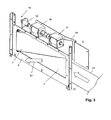
Figur 1 Figur 3- eine perspektivische Darstellung des Umlenkelementes gemäß
Figur 2 Figur 4- eine Draufsicht auf ein Umlenkmodul, bei dem ein Umlenkelement auf einer in Transportrichtung rechten Seite des Tragrahmens angeordnet ist in einer Ausgangsstellung und
Figur 5- eine Draufsicht des Umlenkmoduls gemäß
Figur 4
- FIG. 1
- a sorting device with two deflection modules arranged one behind the other in the transport direction, each of which enables a deflection of objects into a first discharge direction oriented to the left of the conveyor path,
- FIG. 2
- an enlarged view of the deflection according to
FIG. 1 in a starting position of the deflection element, omitting a cover of a support frame, wherein the deflection element is articulated to the support frame and in a top portion of the support frame, a two-stage linear actuator is positioned, - FIG. 3
- a perspective view of the deflecting according to
FIG. 2 in a second pivoting position of the deflection element for deflecting the objects in the first discharge direction, - FIG. 4
- a plan view of a deflection, in which a deflecting element is arranged on a right side in the transport direction of the support frame in a starting position and
- FIG. 5
- a plan view of the deflection according to
FIG. 4 in a second pivoting position of the deflecting element for discharging objects into a second discharge direction oriented to the right of the conveying path.
Eine Vorrichtung zum Sortieren von auf einem Förderband 1 geförderten Gegenständen kann vorzugsweise zur Sortierung von Gebinden bzw. Behältern (Flaschen, Dosen etc.) genutzt werden, die zur sortenreinen Vereinzelung unterschiedlichen Aufnahmen seitlich des Förderbandes 1 zugeführt werden sollen. In
Das Umlenkmodul 3 weist einen Tragrahmen 5 auf, dessen aufrechte und in Transportrichtung 2 erstreckende erste Längsseite 6 und eine gegenüberliegende zweite Längsseite 6' an der Leiste 4 befestigt sind. Auf der einer ersten Ausschleusrichtung A1 zugewandten ersten Längsseite 6 ist ein Umlenkelement 7 schwenkbar um eine senkrecht zur Transportrichtung 2 und senkrecht zu dem Förderband 1 verlaufenden Drehachse D schwenkbar an dem Transportrahmen 5 gelagert. Die Drehachse D erstreckt sich an einer in Transportrichtung 2 vorne angeordneten Vorderseite 8 des Umlenkmoduls 3.The
Wie besser aus den
Das zweistufige Linearstellorgan 10 weist einen Stellbolzen 12 auf, der in Transportrichtung 2 ein- und ausfahrbar ist und über eine Hebelmechanik 13 mit der Drehachse D des Umlenkelementes 7 gekoppelt ist. Im vorliegenden Ausführungsbeispiel weist das Umlenkelement 7 einen Querausleger 14 auf, an dem der an einem ersten Ende 15 des zweistufigen Linearstellorgans 10 angeordnete Stellbolzen 12 gelenkig gelagert ist.The two-stage
Zur Betätigung des Stellbolzens 12 weist das zweistufige Linearstellorgan 10 einen ersten Zugmagneten 16 und einen in Transportrichtung 2 beabstandeten zweiten Zugmagneten 17 auf, die in entgegengesetzter Richtung auslösbar und/oder betätigbar sind. Die über einen Magneten 18 betätigbaren Zugmagneten 16, 17 sind fest miteinander gekoppelt. Eine Rückstellung des ersten Zugmagneten 16 und des zweiten Zugmagneten 17 erfolgt durch Auslösung des zweiten Zugmagneten 17 bzw. des ersten Zugmagneten 16. Eine die Rückstellkraft bewirkende Rückstellfeder weisen die Zugmagneten 16, 17 nicht auf.For actuating the adjusting
Soll sich das Umlenkelement 7 in der neutralen, den Gegenstand nicht umlenkenden ersten Schwenkstellung gemäß
Da die Drehachse D an einer in Transportrichtung 2 gesehenen Vorderseite 8 des Tragrahmens 5 bzw. des Umlenkelementes 7 angeordnet ist, bewirkt das Anstoßen des Gegenstandes gegen das Umlenkelement 7 eine erhöhte Anschlagkraft, die das Umlenkelement 7 in der zweiten Schwenkstellung begünstigt. Der Tragrahmen 5 weist auf der zweiten Längsseite 6' einen Anschlag 19 auf, gegen den das freie Ende des Umlenkelementes 7 in der zweiten Schwenkstellung anstößt.Since the axis of rotation D is arranged on a viewed in the
Das Umlenkelement 7 ist als eine Umlenkklappe ausgebildet, die in einer vertikalen Ebene verläuft und an deren in Transportrichtung 2 gesehenen vorderen Schmalseite 20 die Drehachse D verläuft.The deflecting
Das in den
Nach einer zweiten Ausführungsform der Erfindung kann ein Tragrahmen 5' auch so ausgebildet sein, dass ein Umlenkelement 7' und ein demselben zugeordnetes zweistufiges Linearstellorgan 10 auf einer zu der ersten Ausschleusrichtung A1 gegenüberliegenden zweiten Ausschleusrichtung A2 zugewandt angeordnet sind, nämlich im Bereich der zweiten Längsseite 6' des Tragrahmens 5', siehe
Gleiche Bauteile bzw. Bauteilfunktionen der Ausführungsbeispiele sind mit den gleichen Bezugsziffern versehen.The same components or component functions of the embodiments are provided with the same reference numerals.
Die Ansteuerung des zweistufigen Linearstellorganes 10' erfolgt in der gleichen Weise wie bei der ersten Ausführungsform gemäß den
Nach einer nicht dargestellten weiteren Ausführungsform der Erfindung kann ein Umlenkmodul vorgesehen sein, dass sowohl das erste Umlenkelement 7 als auch das zweite Umlenkelement 7' sowie die dazugehörigen zweistufigen Linearstellorgane 10, 10' aufweist. Die zweistufigen Linearstellorgane 10, 10' können vorzugsweise quer zur Transportrichtung 2 seitlich versetzt nebeneinander angeordnet sein. Vorteilhaft wird hierdurch ein kompaktes Umlenkmodul 3 gebildet, das durch wahlweise Ansteuerung des Umlenkelementes 7 oder 7' ein Ausschleusen der Gegenstände in die erste Ausschleusrichtung A1 oder in die zweite Ausschleusrichtung A2 ermöglicht.According to a further embodiment of the invention, not shown, a deflection module may be provided, that both the
Es ist ersichtlich, dass die Drehachse D aufrecht im Bereich eines Seitenrandes 21 bzw. 21' des Förderbandes 1 bzw. der Förderbahn 11 verläuft, damit eine sichere Umlenkung der Gegenstände in die erste Ausschleusrichtung A1 oder die zweite Ausschleusrichtung A2 gegeben ist. In den vorliegenden Ausführungsbeispielen deckt sich das Förderband 1 mit der Förderbahn 11. Nach einer nicht dargestellten Ausführungsform der Erfindung kann allerdings auch ein relativ breites Förderband vorgesehen sein, so dass mehrere parallele Förderbahnen gebildet sind, entlang derer mehrere Reihen von Gegenständen gleichzeitig in Transportrichtung 2 förderbar sind. Bei dieser Ausführungsform können die Umlenkelemente 7 nicht nur zur Umlenkung in seitlich vom Förderband angeordnete Behälter, sondern auch zum Wechsel der Förderbahn eingesetzt werden. Hierbei müssen sich die Drehachsen D nicht an einem Seitenrand 21, 21' des Förderbandes 1 befinden.It can be seen that the axis of rotation D is upright in the region of a
Nach einer nicht dargestellten Ausführungsform der Erfindung können auch mindestens zwei in Transportrichtung 2 beabstandet zueinander angeordnete Umlenkmodule 3 vorgesehen sein, die jeweils ein erstes Umlenkelement 7 und das demselben zugeordnete zweistufige Linearstellorgan 10 und/oder das zweite Umlenkelement 7' sowie das demselben zugeordnete zweistufige Linearstellorgan 10' aufweisen, so dass sequentiell geförderte Gegenstände wahlweise in die erste Ausschleusrichtung A1 und/oder die zweite Ausschleusrichtung A2 umgelenkt werden.According to a non-illustrated embodiment of the invention, at least two in the
- 11
- Förderbandconveyor belt
- 22
- Transportrichtungtransport direction
- 33
- Umlenkmodulrerouting
- 44
- Leistestrip
- 5, 5'5, 5 '
- Tragrahmensupporting frame
- 6, 6'6, 6 '
- 1. Längsseite, 2. Längsseite1st longitudinal side, 2nd longitudinal side
- 7, 7'7, 7 '
- Umlenkelementdeflecting
- 88th
- Vorderseitefront
- 99
- Oberseitetop
- 10, 10'10, 10 '
- 2stufiges Linearstellorgan2-stage linear actuator
- 1111
- Förderbahnconveyor track
- 1212
- Stellbolzenadjusting bolts
- 1313
- Hebelmechaniklever mechanism
- 1414
- Querausleger (7)Transverse boom (7)
- 1515
- 1. Ende (10)1st end (10)
- 1616
- 1. Zugmagnet1. pull magnet
- 1717
- 2. Zugmagnet2. Pull magnet
- 1818
- Magnetenmagnets
- 19, 19'19, 19 '
- Anschlagattack
- 2020
- Schmalseite (7)Narrow side (7)
- 21, 21'21, 21 '
- Seitenrandmargin
- A1A1
- 1. Ausschleusrichtung1. discharge direction
- A2A2
- 2. Ausschleusrichtung2nd discharge direction
- DD
- Drehachseaxis of rotation
Claims (10)
- Apparatus for sorting articles conveyed on a conveying belt, having a deflecting element which is mounted such that it can be pivoted about an axis of rotation running perpendicularly to the conveying belt and is subjected to the action of an adjustment means, in which case the article, on the one hand in a first pivoting position of the deflecting element, in which the deflecting element extends in the transporting direction of the conveying belt, can be conveyed further in the transporting direction on a conveying path of the conveying belt and, on the other hand in a second pivoting position of the deflecting element, in which the deflecting element extends at an acute angle to the transporting direction of the conveying belt, can be diverted laterally from the conveying path of the conveying belt, characterized
in that the axis of rotation (D) runs in the region of a side periphery of the conveying path (11) and/or of the conveying belt (1), and in that the adjustment means (10, 10') is designed in the form of at least one two-stage linear-adjustment means, which is coupled at the axis of rotation (D) of the deflecting element (7, 7') via a lever mechanism (13), and
in that the two-stage linear-adjustment means (10, 10') is formed by two pull-type magnets (16, 17) which are arranged one behind the other in the transporting direction and are coupled to one another. - Apparatus according to Claim 1, characterized in that the lever mechanism (13) has a transverse extension arm (14), which is connected in a rotationally fixed manner to the deflecting element (7, 7') and on which the two-stage linear-adjustment means (10, 10') acts such that the deflecting element (7, 7') can be moved exclusively into the first pivoting position or into the second pivoting position.
- Apparatus according to Claim 1 or 2, characterized in that the two-stage linear-adjustment means (10, 10'), in order to form the lever mechanism (13), is mounted on the transverse extension arm (14) of the deflecting element (7, 7') in an articulated manner via an adjustment bolt (12), which is arranged in a moveable manner in the transporting direction (2).
- Apparatus according to one of Claims 1 to 3, characterized in that the deflecting element (7, 7') is designed in the form of a deflecting flap with an upright narrow side (20), along which the axis of rotation (D) runs.
- Apparatus according to one of Claims 1 to 4, characterized in that the narrow side (20) of the deflecting element (7, 7'), said narrow side accommodating the axis of rotation (D), forms a front side of the deflecting element (7, 7'), as seen in the transporting direction (2).
- Apparatus according to Claim 1, characterized in that the two pull-type magnets (16, 17) are arranged such that they can be triggered and/or actuated in opposite directions.
- Apparatus according to Claim 1 or 6, characterized in that the pull-type magnets (16, 17) can be activated alternately in order to move the adjustment bolt (12) into a front position, as seen in the transporting direction (2), in which case the deflecting element (7, 7') is located in the second pivoting position, or into a second position, in which the deflecting element (7, 7') is located in the first pivoting position.
- Apparatus according to one of Claims 1 to 7, characterized in that the two-stage linear-adjustment means (10, 10') is arranged in the region of an upper side (9) of a carrying frame (5, 5') and the deflecting element (7, 7') is arranged in the region of a longitudinal side (6, 6') of the carrying frame (5, 5').
- Apparatus according to Claim 8, characterized in that the carrying frame (5, 5') together with the first deflecting element (7), which is arranged on a first longitudinal side (6) of the carrying frame, and the two-stage linear-adjustment means (10), which is assigned to said deflecting element, and/or with the second deflecting element (7'), which is arranged on a second longitudinal side (6') of the carrying frame (5, 5'), and the two-stage linear-adjustment means (10'), which is assigned to said deflecting element, forms a deflecting module (3) in order to deflect the article in a first discharging direction (A1) and/or in a second discharging direction (A2).
- Apparatus according to Claim 9, characterized in that at least two deflecting modules (3) are arranged spaced apart from one another in the transporting direction (2), said modules each having the first deflecting element (7) and the two-stage linear-adjustment means (10), which is assigned to said deflecting element, and/or the second deflecting element (7') and the two-stage linear-adjustment means (10'), which is assigned to said deflecting element, in order to deflect the article optionally in the first discharging direction (A1) and/or in the second discharging direction (A2).
Priority Applications (2)
| Application Number | Priority Date | Filing Date | Title |
|---|---|---|---|
| DK12168616T DK2666738T3 (en) | 2012-05-21 | 2012-05-21 | Appliance for sorting objects |
| EP20120168616 EP2666738B1 (en) | 2012-05-21 | 2012-05-21 | Device for sorting objects |
Applications Claiming Priority (1)
| Application Number | Priority Date | Filing Date | Title |
|---|---|---|---|
| EP20120168616 EP2666738B1 (en) | 2012-05-21 | 2012-05-21 | Device for sorting objects |
Publications (2)
| Publication Number | Publication Date |
|---|---|
| EP2666738A1 EP2666738A1 (en) | 2013-11-27 |
| EP2666738B1 true EP2666738B1 (en) | 2014-09-17 |
Family
ID=46146728
Family Applications (1)
| Application Number | Title | Priority Date | Filing Date |
|---|---|---|---|
| EP20120168616 Not-in-force EP2666738B1 (en) | 2012-05-21 | 2012-05-21 | Device for sorting objects |
Country Status (2)
| Country | Link |
|---|---|
| EP (1) | EP2666738B1 (en) |
| DK (1) | DK2666738T3 (en) |
Families Citing this family (1)
| Publication number | Priority date | Publication date | Assignee | Title |
|---|---|---|---|---|
| DE102018109637A1 (en) | 2018-04-23 | 2019-10-24 | Krones Ag | Device and method for transporting containers |
Family Cites Families (7)
| Publication number | Priority date | Publication date | Assignee | Title |
|---|---|---|---|---|
| US3543916A (en) * | 1968-09-13 | 1970-12-01 | Westinghouse Air Brake Co | Flow diverting shaker conveyor trough |
| US4643291A (en) * | 1986-01-21 | 1987-02-17 | Rexnord Inc. | Linear articulated pusher |
| EP1276684B1 (en) | 2000-03-31 | 2005-11-23 | Tomra Systems A/S | Apparatuses for the conveying, lifting and sorting of articles |
| US6615972B2 (en) * | 2000-04-27 | 2003-09-09 | Rapistan Systems Advertising Corp. | Sortation system diverter switch |
| DE10354777B4 (en) * | 2003-11-21 | 2008-03-27 | Sult Gmbh | Sorting device for sorting different substances |
| US7147097B2 (en) * | 2004-09-30 | 2006-12-12 | Laitram, L.L.C. | Transverse-roller-belt sorter with automated guide |
| US20100006393A1 (en) * | 2008-07-14 | 2010-01-14 | Jervis B. Webb Company | Diverter Assembly |
-
2012
- 2012-05-21 EP EP20120168616 patent/EP2666738B1/en not_active Not-in-force
- 2012-05-21 DK DK12168616T patent/DK2666738T3/en active
Also Published As
| Publication number | Publication date |
|---|---|
| EP2666738A1 (en) | 2013-11-27 |
| DK2666738T3 (en) | 2014-12-08 |
Similar Documents
| Publication | Publication Date | Title |
|---|---|---|
| DE60118948T2 (en) | TRANSFER OF OBJECTS BETWEEN PROMOTED TRANSFERS | |
| EP1474348B1 (en) | Conveyor | |
| EP3072834B1 (en) | Conveying device with a transport rake | |
| WO2004089790A1 (en) | Device for changing the direction of conveyance of flat postal items and the position of the postal items relative to their direction of conveyance | |
| DE102011109967A1 (en) | Gripper for transporting resilient food product e.g. meat in production plant, has lever that is connected to driver work area, such that endless transportation belt is moved due to rotational movement of lever | |
| DE102008047279A1 (en) | Device for sorting containers | |
| EP3433189A1 (en) | Gripping apparatus and transporting device for transporting containers | |
| DE10301178B4 (en) | Device for aligning and distributing | |
| DE2943516A1 (en) | CONVEYOR WITH TILTABLE CARRIERS | |
| DE2014915B2 (en) | Drag chain conveyor system | |
| DE2552360C2 (en) | Workpiece elevator | |
| DE102009040604A1 (en) | Device for distributing beverage crates on e.g. conveyor belt in logistic field, has redirecting handle moved by pneumatic, electric or hydraulic actuated drive and extended from conveyor path in case of straight-line passing of crates | |
| WO2008012214A1 (en) | Distributing device for loose articles | |
| EP2666738B1 (en) | Device for sorting objects | |
| EP1352858A2 (en) | Sorting device with tiltable goods carriers | |
| DE19681062C1 (en) | Conveyor device, particular for internal operable suspended conveyance | |
| DE102021209986A1 (en) | Handling system for the automatic transfer and separation of load carriers | |
| DD229325A5 (en) | COMPACTING DEVICE FOR USE IN A FOUNDRY EQUIPMENT | |
| DE19844796C2 (en) | Rail-like conveyor line | |
| DE10261551B4 (en) | rotator | |
| EP0624532B1 (en) | Device for sorting bottles or similar containers | |
| DE2352424A1 (en) | CONVEYOR FOR TRANSPORTING NEWSPAPER FLAPS AND - PACKAGES | |
| DE102006001581A1 (en) | Holding device for stacking boards has receiving sector, lifting device and issuing device including traveler able to engage with stacking board | |
| EP0065080A1 (en) | Conveyor system provided with a conveyor floor for work-pieces and/or work-piece supports | |
| EP1717179A1 (en) | Device for stablilizing printed products transported in a stream along a transport path, hanging in grippers of a transport device |
Legal Events
| Date | Code | Title | Description |
|---|---|---|---|
| PUAI | Public reference made under article 153(3) epc to a published international application that has entered the european phase |
Free format text: ORIGINAL CODE: 0009012 |
|
| AK | Designated contracting states |
Kind code of ref document: A1 Designated state(s): AL AT BE BG CH CY CZ DE DK EE ES FI FR GB GR HR HU IE IS IT LI LT LU LV MC MK MT NL NO PL PT RO RS SE SI SK SM TR |
|
| AX | Request for extension of the european patent |
Extension state: BA ME |
|
| 17P | Request for examination filed |
Effective date: 20131106 |
|
| RBV | Designated contracting states (corrected) |
Designated state(s): AL AT BE BG CH CY CZ DE DK EE ES FI FR GB GR HR HU IE IS IT LI LT LU LV MC MK MT NL NO PL PT RO RS SE SI SK SM TR |
|
| 17Q | First examination report despatched |
Effective date: 20131213 |
|
| GRAP | Despatch of communication of intention to grant a patent |
Free format text: ORIGINAL CODE: EPIDOSNIGR1 |
|
| INTG | Intention to grant announced |
Effective date: 20140522 |
|
| GRAS | Grant fee paid |
Free format text: ORIGINAL CODE: EPIDOSNIGR3 |
|
| GRAA | (expected) grant |
Free format text: ORIGINAL CODE: 0009210 |
|
| AK | Designated contracting states |
Kind code of ref document: B1 Designated state(s): AL AT BE BG CH CY CZ DE DK EE ES FI FR GB GR HR HU IE IS IT LI LT LU LV MC MK MT NL NO PL PT RO RS SE SI SK SM TR |
|
| REG | Reference to a national code |
Ref country code: GB Ref legal event code: FG4D Free format text: NOT ENGLISH |
|
| REG | Reference to a national code |
Ref country code: CH Ref legal event code: EP |
|
| REG | Reference to a national code |
Ref country code: IE Ref legal event code: FG4D Free format text: LANGUAGE OF EP DOCUMENT: GERMAN |
|
| REG | Reference to a national code |
Ref country code: AT Ref legal event code: REF Ref document number: 687591 Country of ref document: AT Kind code of ref document: T Effective date: 20141015 |
|
| REG | Reference to a national code |
Ref country code: DE Ref legal event code: R096 Ref document number: 502012001261 Country of ref document: DE Effective date: 20141030 |
|
| REG | Reference to a national code |
Ref country code: DK Ref legal event code: T3 Effective date: 20141205 |
|
| REG | Reference to a national code |
Ref country code: SE Ref legal event code: TRGR |
|
| PG25 | Lapsed in a contracting state [announced via postgrant information from national office to epo] |
Ref country code: GR Free format text: LAPSE BECAUSE OF FAILURE TO SUBMIT A TRANSLATION OF THE DESCRIPTION OR TO PAY THE FEE WITHIN THE PRESCRIBED TIME-LIMIT Effective date: 20141218 Ref country code: LT Free format text: LAPSE BECAUSE OF FAILURE TO SUBMIT A TRANSLATION OF THE DESCRIPTION OR TO PAY THE FEE WITHIN THE PRESCRIBED TIME-LIMIT Effective date: 20140917 |
|
| REG | Reference to a national code |
Ref country code: NO Ref legal event code: T2 Effective date: 20140917 |
|
| REG | Reference to a national code |
Ref country code: NL Ref legal event code: VDEP Effective date: 20140917 |
|
| REG | Reference to a national code |
Ref country code: LT Ref legal event code: MG4D |
|
| PG25 | Lapsed in a contracting state [announced via postgrant information from national office to epo] |
Ref country code: LV Free format text: LAPSE BECAUSE OF FAILURE TO SUBMIT A TRANSLATION OF THE DESCRIPTION OR TO PAY THE FEE WITHIN THE PRESCRIBED TIME-LIMIT Effective date: 20140917 Ref country code: CY Free format text: LAPSE BECAUSE OF FAILURE TO SUBMIT A TRANSLATION OF THE DESCRIPTION OR TO PAY THE FEE WITHIN THE PRESCRIBED TIME-LIMIT Effective date: 20140917 Ref country code: RS Free format text: LAPSE BECAUSE OF FAILURE TO SUBMIT A TRANSLATION OF THE DESCRIPTION OR TO PAY THE FEE WITHIN THE PRESCRIBED TIME-LIMIT Effective date: 20140917 Ref country code: HR Free format text: LAPSE BECAUSE OF FAILURE TO SUBMIT A TRANSLATION OF THE DESCRIPTION OR TO PAY THE FEE WITHIN THE PRESCRIBED TIME-LIMIT Effective date: 20140917 |
|
| PG25 | Lapsed in a contracting state [announced via postgrant information from national office to epo] |
Ref country code: NL Free format text: LAPSE BECAUSE OF FAILURE TO SUBMIT A TRANSLATION OF THE DESCRIPTION OR TO PAY THE FEE WITHIN THE PRESCRIBED TIME-LIMIT Effective date: 20140917 |
|
| PG25 | Lapsed in a contracting state [announced via postgrant information from national office to epo] |
Ref country code: CZ Free format text: LAPSE BECAUSE OF FAILURE TO SUBMIT A TRANSLATION OF THE DESCRIPTION OR TO PAY THE FEE WITHIN THE PRESCRIBED TIME-LIMIT Effective date: 20140917 Ref country code: PT Free format text: LAPSE BECAUSE OF FAILURE TO SUBMIT A TRANSLATION OF THE DESCRIPTION OR TO PAY THE FEE WITHIN THE PRESCRIBED TIME-LIMIT Effective date: 20150119 Ref country code: SK Free format text: LAPSE BECAUSE OF FAILURE TO SUBMIT A TRANSLATION OF THE DESCRIPTION OR TO PAY THE FEE WITHIN THE PRESCRIBED TIME-LIMIT Effective date: 20140917 Ref country code: ES Free format text: LAPSE BECAUSE OF FAILURE TO SUBMIT A TRANSLATION OF THE DESCRIPTION OR TO PAY THE FEE WITHIN THE PRESCRIBED TIME-LIMIT Effective date: 20140917 Ref country code: IS Free format text: LAPSE BECAUSE OF FAILURE TO SUBMIT A TRANSLATION OF THE DESCRIPTION OR TO PAY THE FEE WITHIN THE PRESCRIBED TIME-LIMIT Effective date: 20150117 Ref country code: EE Free format text: LAPSE BECAUSE OF FAILURE TO SUBMIT A TRANSLATION OF THE DESCRIPTION OR TO PAY THE FEE WITHIN THE PRESCRIBED TIME-LIMIT Effective date: 20140917 Ref country code: RO Free format text: LAPSE BECAUSE OF FAILURE TO SUBMIT A TRANSLATION OF THE DESCRIPTION OR TO PAY THE FEE WITHIN THE PRESCRIBED TIME-LIMIT Effective date: 20140917 |
|
| PG25 | Lapsed in a contracting state [announced via postgrant information from national office to epo] |
Ref country code: PL Free format text: LAPSE BECAUSE OF FAILURE TO SUBMIT A TRANSLATION OF THE DESCRIPTION OR TO PAY THE FEE WITHIN THE PRESCRIBED TIME-LIMIT Effective date: 20140917 |
|
| REG | Reference to a national code |
Ref country code: DE Ref legal event code: R097 Ref document number: 502012001261 Country of ref document: DE |
|
| PLBE | No opposition filed within time limit |
Free format text: ORIGINAL CODE: 0009261 |
|
| STAA | Information on the status of an ep patent application or granted ep patent |
Free format text: STATUS: NO OPPOSITION FILED WITHIN TIME LIMIT |
|
| 26N | No opposition filed |
Effective date: 20150618 |
|
| PG25 | Lapsed in a contracting state [announced via postgrant information from national office to epo] |
Ref country code: IT Free format text: LAPSE BECAUSE OF FAILURE TO SUBMIT A TRANSLATION OF THE DESCRIPTION OR TO PAY THE FEE WITHIN THE PRESCRIBED TIME-LIMIT Effective date: 20140917 |
|
| PG25 | Lapsed in a contracting state [announced via postgrant information from national office to epo] |
Ref country code: SI Free format text: LAPSE BECAUSE OF FAILURE TO SUBMIT A TRANSLATION OF THE DESCRIPTION OR TO PAY THE FEE WITHIN THE PRESCRIBED TIME-LIMIT Effective date: 20140917 |
|
| REG | Reference to a national code |
Ref country code: CH Ref legal event code: PL |
|
| PG25 | Lapsed in a contracting state [announced via postgrant information from national office to epo] |
Ref country code: CH Free format text: LAPSE BECAUSE OF NON-PAYMENT OF DUE FEES Effective date: 20150531 Ref country code: LU Free format text: LAPSE BECAUSE OF FAILURE TO SUBMIT A TRANSLATION OF THE DESCRIPTION OR TO PAY THE FEE WITHIN THE PRESCRIBED TIME-LIMIT Effective date: 20150521 Ref country code: MC Free format text: LAPSE BECAUSE OF FAILURE TO SUBMIT A TRANSLATION OF THE DESCRIPTION OR TO PAY THE FEE WITHIN THE PRESCRIBED TIME-LIMIT Effective date: 20140917 Ref country code: LI Free format text: LAPSE BECAUSE OF NON-PAYMENT OF DUE FEES Effective date: 20150531 |
|
| REG | Reference to a national code |
Ref country code: IE Ref legal event code: MM4A |
|
| REG | Reference to a national code |
Ref country code: FR Ref legal event code: ST Effective date: 20160129 |
|
| PG25 | Lapsed in a contracting state [announced via postgrant information from national office to epo] |
Ref country code: IE Free format text: LAPSE BECAUSE OF NON-PAYMENT OF DUE FEES Effective date: 20150521 |
|
| PG25 | Lapsed in a contracting state [announced via postgrant information from national office to epo] |
Ref country code: FR Free format text: LAPSE BECAUSE OF NON-PAYMENT OF DUE FEES Effective date: 20150601 |
|
| PG25 | Lapsed in a contracting state [announced via postgrant information from national office to epo] |
Ref country code: MT Free format text: LAPSE BECAUSE OF FAILURE TO SUBMIT A TRANSLATION OF THE DESCRIPTION OR TO PAY THE FEE WITHIN THE PRESCRIBED TIME-LIMIT Effective date: 20140917 |
|
| GBPC | Gb: european patent ceased through non-payment of renewal fee |
Effective date: 20160521 |
|
| PG25 | Lapsed in a contracting state [announced via postgrant information from national office to epo] |
Ref country code: HU Free format text: LAPSE BECAUSE OF FAILURE TO SUBMIT A TRANSLATION OF THE DESCRIPTION OR TO PAY THE FEE WITHIN THE PRESCRIBED TIME-LIMIT; INVALID AB INITIO Effective date: 20120521 Ref country code: GB Free format text: LAPSE BECAUSE OF NON-PAYMENT OF DUE FEES Effective date: 20160521 Ref country code: BG Free format text: LAPSE BECAUSE OF FAILURE TO SUBMIT A TRANSLATION OF THE DESCRIPTION OR TO PAY THE FEE WITHIN THE PRESCRIBED TIME-LIMIT Effective date: 20140917 Ref country code: SM Free format text: LAPSE BECAUSE OF FAILURE TO SUBMIT A TRANSLATION OF THE DESCRIPTION OR TO PAY THE FEE WITHIN THE PRESCRIBED TIME-LIMIT Effective date: 20140917 |
|
| PG25 | Lapsed in a contracting state [announced via postgrant information from national office to epo] |
Ref country code: BE Free format text: LAPSE BECAUSE OF NON-PAYMENT OF DUE FEES Effective date: 20150531 |
|
| PG25 | Lapsed in a contracting state [announced via postgrant information from national office to epo] |
Ref country code: TR Free format text: LAPSE BECAUSE OF FAILURE TO SUBMIT A TRANSLATION OF THE DESCRIPTION OR TO PAY THE FEE WITHIN THE PRESCRIBED TIME-LIMIT Effective date: 20140917 |
|
| PG25 | Lapsed in a contracting state [announced via postgrant information from national office to epo] |
Ref country code: MK Free format text: LAPSE BECAUSE OF FAILURE TO SUBMIT A TRANSLATION OF THE DESCRIPTION OR TO PAY THE FEE WITHIN THE PRESCRIBED TIME-LIMIT Effective date: 20140917 |
|
| PG25 | Lapsed in a contracting state [announced via postgrant information from national office to epo] |
Ref country code: AL Free format text: LAPSE BECAUSE OF FAILURE TO SUBMIT A TRANSLATION OF THE DESCRIPTION OR TO PAY THE FEE WITHIN THE PRESCRIBED TIME-LIMIT Effective date: 20140917 |
|
| PGFP | Annual fee paid to national office [announced via postgrant information from national office to epo] |
Ref country code: IT Payment date: 20190624 Year of fee payment: 15 |
|
| PGFP | Annual fee paid to national office [announced via postgrant information from national office to epo] |
Ref country code: AT Payment date: 20190423 Year of fee payment: 8 |
|
| REG | Reference to a national code |
Ref country code: DK Ref legal event code: EBP Effective date: 20200531 |
|
| REG | Reference to a national code |
Ref country code: AT Ref legal event code: MM01 Ref document number: 687591 Country of ref document: AT Kind code of ref document: T Effective date: 20200521 |
|
| PG25 | Lapsed in a contracting state [announced via postgrant information from national office to epo] |
Ref country code: AT Free format text: LAPSE BECAUSE OF NON-PAYMENT OF DUE FEES Effective date: 20200521 |
|
| PG25 | Lapsed in a contracting state [announced via postgrant information from national office to epo] |
Ref country code: DK Free format text: LAPSE BECAUSE OF NON-PAYMENT OF DUE FEES Effective date: 20200531 |
|
| PGFP | Annual fee paid to national office [announced via postgrant information from national office to epo] |
Ref country code: SE Payment date: 20220523 Year of fee payment: 11 Ref country code: NO Payment date: 20220520 Year of fee payment: 11 Ref country code: DE Payment date: 20220429 Year of fee payment: 11 |
|
| PGFP | Annual fee paid to national office [announced via postgrant information from national office to epo] |
Ref country code: FI Payment date: 20220517 Year of fee payment: 11 |
|
| REG | Reference to a national code |
Ref country code: DE Ref legal event code: R119 Ref document number: 502012001261 Country of ref document: DE |
|
| REG | Reference to a national code |
Ref country code: NO Ref legal event code: MMEP |
|
| REG | Reference to a national code |
Ref country code: SE Ref legal event code: EUG |
|
| PG25 | Lapsed in a contracting state [announced via postgrant information from national office to epo] |
Ref country code: SE Free format text: LAPSE BECAUSE OF NON-PAYMENT OF DUE FEES Effective date: 20230522 Ref country code: NO Free format text: LAPSE BECAUSE OF NON-PAYMENT OF DUE FEES Effective date: 20230531 Ref country code: FI Free format text: LAPSE BECAUSE OF NON-PAYMENT OF DUE FEES Effective date: 20230521 |