EP2666711A1 - Unterseeboot - Google Patents
Unterseeboot Download PDFInfo
- Publication number
- EP2666711A1 EP2666711A1 EP13159797.3A EP13159797A EP2666711A1 EP 2666711 A1 EP2666711 A1 EP 2666711A1 EP 13159797 A EP13159797 A EP 13159797A EP 2666711 A1 EP2666711 A1 EP 2666711A1
- Authority
- EP
- European Patent Office
- Prior art keywords
- valve
- shut
- cylinder
- piston rod
- opening
- Prior art date
- Legal status (The legal status is an assumption and is not a legal conclusion. Google has not performed a legal analysis and makes no representation as to the accuracy of the status listed.)
- Granted
Links
Images

Classifications
-
- F—MECHANICAL ENGINEERING; LIGHTING; HEATING; WEAPONS; BLASTING
- F16—ENGINEERING ELEMENTS AND UNITS; GENERAL MEASURES FOR PRODUCING AND MAINTAINING EFFECTIVE FUNCTIONING OF MACHINES OR INSTALLATIONS; THERMAL INSULATION IN GENERAL
- F16K—VALVES; TAPS; COCKS; ACTUATING-FLOATS; DEVICES FOR VENTING OR AERATING
- F16K31/00—Actuating devices; Operating means; Releasing devices
- F16K31/12—Actuating devices; Operating means; Releasing devices actuated by fluid
- F16K31/122—Actuating devices; Operating means; Releasing devices actuated by fluid the fluid acting on a piston
- F16K31/1221—Actuating devices; Operating means; Releasing devices actuated by fluid the fluid acting on a piston one side of the piston being spring-loaded
-
- B—PERFORMING OPERATIONS; TRANSPORTING
- B63—SHIPS OR OTHER WATERBORNE VESSELS; RELATED EQUIPMENT
- B63G—OFFENSIVE OR DEFENSIVE ARRANGEMENTS ON VESSELS; MINE-LAYING; MINE-SWEEPING; SUBMARINES; AIRCRAFT CARRIERS
- B63G8/00—Underwater vessels, e.g. submarines; Equipment specially adapted therefor
- B63G8/14—Control of attitude or depth
- B63G8/22—Adjustment of buoyancy by water ballasting; Emptying equipment for ballast tanks
-
- B—PERFORMING OPERATIONS; TRANSPORTING
- B63—SHIPS OR OTHER WATERBORNE VESSELS; RELATED EQUIPMENT
- B63B—SHIPS OR OTHER WATERBORNE VESSELS; EQUIPMENT FOR SHIPPING
- B63B13/00—Conduits for emptying or ballasting; Self-bailing equipment; Scuppers
-
- F—MECHANICAL ENGINEERING; LIGHTING; HEATING; WEAPONS; BLASTING
- F16—ENGINEERING ELEMENTS AND UNITS; GENERAL MEASURES FOR PRODUCING AND MAINTAINING EFFECTIVE FUNCTIONING OF MACHINES OR INSTALLATIONS; THERMAL INSULATION IN GENERAL
- F16K—VALVES; TAPS; COCKS; ACTUATING-FLOATS; DEVICES FOR VENTING OR AERATING
- F16K1/00—Lift valves or globe valves, i.e. cut-off apparatus with closure members having at least a component of their opening and closing motion perpendicular to the closing faces
- F16K1/12—Lift valves or globe valves, i.e. cut-off apparatus with closure members having at least a component of their opening and closing motion perpendicular to the closing faces with streamlined valve member around which the fluid flows when the valve is opened
- F16K1/126—Lift valves or globe valves, i.e. cut-off apparatus with closure members having at least a component of their opening and closing motion perpendicular to the closing faces with streamlined valve member around which the fluid flows when the valve is opened actuated by fluid
-
- F—MECHANICAL ENGINEERING; LIGHTING; HEATING; WEAPONS; BLASTING
- F16—ENGINEERING ELEMENTS AND UNITS; GENERAL MEASURES FOR PRODUCING AND MAINTAINING EFFECTIVE FUNCTIONING OF MACHINES OR INSTALLATIONS; THERMAL INSULATION IN GENERAL
- F16K—VALVES; TAPS; COCKS; ACTUATING-FLOATS; DEVICES FOR VENTING OR AERATING
- F16K31/00—Actuating devices; Operating means; Releasing devices
- F16K31/12—Actuating devices; Operating means; Releasing devices actuated by fluid
- F16K31/122—Actuating devices; Operating means; Releasing devices actuated by fluid the fluid acting on a piston
Definitions
- the invention relates to a submarine with the features specified in the preamble of claim 1.
- Submarines typically have multiple submersible cells outside their pressure hull, which give the submarines the ability to descend from an overwater floating position to an underwater buoyancy or, conversely, ascend from an underwater buoyancy to an overwater buoyancy. To initiate the dive, these immersion cells are flooded with water and blown out to re-emergence on the water surface with a gas or gas mixture such as air.
- the immersion cells each have one, but possibly also a plurality of openings, through which water can flow during the flooding of the immersion cells and can flow out when the immersion cells are blown out.
- a venting device for the immersion cells further openings are formed on the immersion cells in an upper region, via which gas or air located in the immersion cells can escape during the flooding of the immersion cells.
- the latter openings are closed by mechanically actuated valves, which release a flow path from the interior of the immersion cell to its external environment during flooding of the immersion cells, respectively, and close this flow path when the immersion cell is blown out and the submarine floats above.
- the valves arranged thereon can not be actuated directly, but are via mechanical Transmission and cardan shafts with operatively arranged in the interior of the pressure body actuating means. This makes the venting devices for the immersion cells in constructive, manufacturing and assembly technical view comparatively expensive.
- the invention has for its object to provide a submarine, which is significantly simplified in terms of the design, manufacture and installation of the venting devices for the dipping.
- the submarine according to the invention has, in a manner known per se, at least one immersion cell, which is arranged outside the pressure hull of the submarine.
- This dipping cell has at least one opening closed by a shut-off valve.
- This opening which is typically formed at an upper portion of the immersion cell, forms a flow path from the interior of the immersion cell to the outside environment of the immersion cell.
- a gas or gas mixture in the immersion cell can escape from the immersion cell via the open opening.
- the basic idea of the invention is to use a fluidically controllable shut-off valve for closing the opening formed on the immersion cell. That is, it is a shut-off valve with a Actuator is provided, which opens the shutoff valve opening or closing upon appropriate exposure to a fluid, which may be air or a liquid.
- a fluid which may be air or a liquid.
- the shut-off valve or its actuator must be line connected only with a suitable fluid supply and appropriate means for controlling the fluid supply of the actuator may be present.
- a fluid supply for example, existing in the submarine compressed air supply or a likewise existing hydraulic network of the submarine can be used.
- the means for venting the dipping cell are essentially limited to the shut-off valve, a line connection of this shut-off valve with a fluid supply and a control device for controlling the fluid supply. Accordingly, the venting device of the submarine according to the invention is much simpler than in the hitherto known submarines, which has a particularly advantageous effect on their production and assembly.
- the submersible cells of a submarine must each be equipped with at least two openings, of which a serving for flooding the dipping cell opening is preferably formed in a keel-side region of the immersion cell and serving for venting the immersion cell opening is advantageously formed on the upper side of the immersion cell.
- All openings of the immersion cell serving for venting the immersion cell are each closed by a shut-off valve. At least one of these shut-off valves, but preferably all shut-off valves are designed to be fluidically controllable in the submarine according to the invention in the manner described above.
- the shut-off valve may be designed to be pneumatically and hydraulically controllable, although a hydraulically controllable Embodiment is preferred, since this allows larger actuating forces for setting the shut-off valve.
- a sealing body of the shut-off valve is movement-coupled with a piston rod of a hydraulic cylinder.
- the shut-off valve is therefore preferably a lifting valve with an actuator, which is formed by a hydraulic cylinder.
- the piston and the piston rod formed thereon, to which the sealing body of the shut-off valve is preferably directly attached are moved such that the sealing body releases a flow path formed by the opening of the immersion cell and the shut-off valve and at opposite movement of the piston and the piston rod closes.
- the shut-off valve can be biased in the closing direction.
- at least one spring element can be provided, which exerts on the sealing body of the shut-off valve both in the closed position of the shut-off valve and in the open position of the closing body a spring force which acts in the closing direction of the sealing body.
- the prestressed spring element can prevent the shut-off valve from inadvertently opening when a shock load acts on the submarine, by providing an additional holding force which holds the sealing body of the shut-off valve in its closed position.
- a hydraulic cylinder forming the actuator of the shut-off valve is preferably designed as a double-acting cylinder with a first cylinder chamber pressurized during the extension stroke of the piston rod and a second cylinder chamber pressurized during the retraction stroke of the piston rod. This is advantageous in that in the hydraulic cylinder both the extension stroke and the retraction stroke can be actively controlled by introducing the hydraulic fluid into the corresponding cylinder chamber.
- the hydraulic cylinder is preferably designed and / or arranged such that it moves the sealing body during the extension stroke into an opening position and moves it during the retraction stroke into the closed position. That is, when Fluidbeetzung the first cylinder chamber of the hydraulic cylinder, the shut-off valve is opened and upon fluid loading of the second cylinder chamber, the shut-off valve is closed.
- a return spring is advantageously arranged in the second cylinder chamber of the hydraulic cylinder. This return spring ensures in the absence or insufficient hydraulic pressure, that when the piston rod is extended with the sealing body and is in the open position, is moved by the spring force of the return spring back into the closed position of the seal body and is held there by the return spring.
- the return spring is preferably a helical spring, which may advantageously be arranged around the piston rod.
- the return spring on the piston and an opposite end of the piston of the hydraulic cylinder through which the piston rod is guided support.
- a sleeve is arranged around the piston rod, which limits the extension stroke of the piston rod.
- this sleeve indicates one end of a collar-shaped radial extension, with which it preferably rests on the piston.
- the sleeve can be held in this position by a return spring arranged around the piston rod and the sleeve, which is supported on the side facing away from the piston side of the extension of the sleeve.
- the shut-off valve is arranged on an outer side of the immersion cell.
- this preferably has a flange, which is attached to the edge of an opening of the dipping cell resting.
- an opening of the flange ring that is a free space enclosed by the flange ring together with the opening formed on the immersion cell forms a flow path from the interior of the immersion cell to its outer environment and vice versa.
- the diameter of the opening formed on the flange ring is less than the diameter of the opening to be closed with the shut-off valve, so that an edge region adjoining the opening of the flange ring protrudes radially inward with respect to the edge which forms the opening formed on the immersion cell.
- the end face of the flange ring resting on the edge of the opening forms a valve seat of the shut-off valve. That is, the annular portion projecting toward the inside of the opening at the edge of the opening of the immersion cell the immersion cell facing end face of the flange ring forms a contact surface for the sealing body of the shut-off valve in its closed position.
- This sealing body is preferably a valve disk, the shut-off valve is therefore preferably a poppet valve.
- the sealing body In order to release the flow path of the shut-off valve formed by the flange ring, the sealing body is to be moved away from the flange ring in the direction of the interior of the immersion cell from its closed position, in which it bears against the side of the flange ring facing the immersion cell.
- a hydraulic cylinder used for this purpose is preferably arranged outside the immersion cell.
- a holder for the hydraulic cylinder is formed on a side facing away from the immersion cell side of the flange.
- the hydraulic cylinder is suitably held such that the piston rod of the hydraulic cylinder, on which the sealing body of the shut-off valve is arranged, in the axial direction of the flange in the direction of the opening and engages in the extended state of the piston of the hydraulic cylinder through the opening of the flange.
- the holder for the hydraulic cylinder advantageously does not protrude in the radial direction beyond the outer edge of the flange ring.
- the shut-off valve shown in the drawing has a flange 2 with an inner opening 4.
- the shut-off valve is fastened to a dipping cell, not shown in the drawing, of a submarine in the region of an opening formed on the dipping cell, one end face 6 (FIG. Fig. 3 ) of the flange 2 rests on the outside of the immersion cell.
- the diameter of the formed on the flange ring 4 opening 4 is smaller than the diameter of the opening formed on the dipping cell, so that the flange 2 with a portion adjacent to the opening 4 ring portion formed on the dipping cell opening partially covers the edge and with a to the outer edge of the Flange ring 2 adjacent ring section rests on the outside of the immersion cell.
- the flange 2 has evenly distributed around its circumference eighteen holes 8. These holes 8 are used to hold screws with which the flange 2 is bolted to the dipping cell.
- three retaining elements 12 are arranged on the circumference of the flange 2 each offset at an angle of 120 °.
- the holding elements 12 are curved in an arcuate manner in the direction of the center of the flange ring 2, wherein a portion spaced from the flange ring 2 in this section , Normal to the end face 10 of the flange 2 aligned end face 14 of the support members 12 disposed in the clearance space of the opening 4 of the flange 2 is.
- a shoulder 16 is formed on the holding elements 12 in each case.
- the holding elements 12 form a holder 18 for a hydraulic cylinder 20.
- the hydraulic cylinder 20 has a cylinder 22.
- a projection 24 is formed through which a stepped bore 26 leads into the interior of the cylinder 22.
- a connection part 28 is screwed for connection of a hydraulic supply line, not shown.
- the connection part 28 is provided with a central bore 30, via which hydraulic fluid can be conducted from the supply line into the interior of the cylinder 22.
- the cylinder 22 is flared on its outer side. In this open end of the cylinder 22 engages an end piece 32 a.
- the end piece 32 has at its end located outside of the cylinder 22 also has a flange-like extension, which corresponds to the flange-like extension of the cylinder 22. In the area of this flange-like extension, the end piece 32 is screwed to the cylinder 22.
- the hydraulic cylinder 20 is circumferentially connected to the holding elements 22 in the region of the end sides 14.
- the flange-like extension of the cylinder 22 and the flange-like extension of the end piece 32 are based on the shoulders 16 formed on the retaining elements 12.
- a displaceable in the longitudinal direction of the cylinder 22 piston 34 is arranged.
- the piston 34 divides the cylinder 22 into a first cylinder chamber 36 and a second cylinder chamber 38.
- the cylinder 22 is designed as a double-acting cylinder.
- the cylinder chamber 36 can be acted upon via the connecting part 28 with a hydraulic pressure.
- a second connecting part is arranged on the cylinder 22, via which hydraulic fluid can be introduced into the second cylinder chamber 38.
- a piston rod 40 is formed on a second cylinder chamber 38 bounding side of the piston 34.
- An end portion of the piston rod 40 facing away from the piston 34 is guided by a central opening formed on the end piece 32 and projects out of the cylinder 22 there.
- a sleeve 42 is arranged, which surrounds the piston rod 40 and at its end facing the piston 34 has an annular cantilevered extension, with which the sleeve 42 abuts against the piston 34.
- a coil spring 44 is disposed around the piston rod 40 and the sleeve 42. The coil spring 44 is supported with its end facing the piston 34 on the outwardly cantilever extension of the sleeve 42 and with its end facing away from the end piece 32 from.
- a sealing body 46 of the shut-off valve is attached.
- this seal body 46 is a valve plate, which comes into abutment in a closed position of the shut-off valve on the end face 6 of the flange 2.
- Fig. 3 shows the sealing body 46 both in a closed position A and in an open position B.
- the cylinder chamber 38 of the cylinder 22 is pressurized with hydraulic fluid and thus keeps the sealing body 46 in the closed position.
- the coil spring 44 arranged in the cylinder chamber 38 is pretensioned under pressure, so that the helical spring 44 likewise exerts a closing force on the piston 34 and thus on the sealing body 46. If the sealing body 46 is to be moved into the open position B, hydraulic fluid is conducted into the cylinder chamber 36 and at the same time the hydraulic fluid in the cylinder chamber 38 is discharged from the cylinder chamber 38.
- the hydraulic fluid flowing into the cylinder chamber 36 presses the piston 34 against the spring force of the coil spring 44, which is further biased to pressure, in the direction of the end piece 32.
- the sealing body 46 arranged on the piston rod 40 releases from the end face 6 of the flange ring 2 formed valve seat.
- the movement of the piston 34 in the direction of the end piece 32 is limited by the fact that the end 32 of the end facing the sleeve 42 comes to rest on the end piece 32, whereby an overload of the coil spring 44 is prevented. If the sealing body 46 is to be moved back from the open position B back into the closed position A, hydraulic fluid is again introduced into the cylinder chamber 38 and the hydraulic fluid is discharged from the cylinder chamber 36.
- the pressure-biased coil spring 44 presses the piston 34 in the retraction direction until the sealing body 46 comes to rest gas-tight on the end face 6 of the flange ring 2 in the closed position , Since the coil spring 44 has a certain bias even in the closed position of the seal body 46, the seal body 46 is held by the coil spring 44 in the closed position.
Landscapes
- Engineering & Computer Science (AREA)
- Mechanical Engineering (AREA)
- General Engineering & Computer Science (AREA)
- Aviation & Aerospace Engineering (AREA)
- Chemical & Material Sciences (AREA)
- Combustion & Propulsion (AREA)
- Ocean & Marine Engineering (AREA)
- Physics & Mathematics (AREA)
- Fluid Mechanics (AREA)
- Actuator (AREA)
Abstract
Description
- Die Erfindung betrifft ein Unterseeboot mit den im Oberbegriff von Anspruch 1 angegebenen Merkmalen.
- Unterseeboote weisen in der Regel außerhalb ihres Druckkörpers mehrere Tauchzellen auf, die den Unterseebooten die Fähigkeit verleihen, von einer Überwasserschwimmlage in eine Unterwasserschwimmlage abzusinken oder umgekehrt von einer Unterwasserschwimmlage in eine Überwasserschwimmlage aufzusteigen. Zur Einleitung der Tauchfahrt werden diese Tauchzellen mit Wasser geflutet und zum Wiederaufstieg an die Wasseroberfläche mit einem Gas oder Gasgemisch wie Luft ausgeblasen.
- In einem kielseitigen Bereich weisen die Tauchzellen jeweils eine, ggf. aber auch mehrere Öffnungen auf, über die Wasser beim Fluten der Tauchzellen in diese einströmen und beim Ausblasen der Tauchzellen ausströmen kann. Als Teil einer Entlüftungseinrichtung für die Tauchzellen sind an den Tauchzellen in einem oberen Bereich weitere Öffnungen ausgebildet, über die in den Tauchzellen befindliches Gas oder Luft beim Fluten der Tauchzellen entweichen kann. Letztgenannte Öffnungen werden von mechanisch betätigten Ventilen verschlossen, die beim Fluten der Tauchzellen jeweils einen Strömungspfad von dem Inneren der Tauchzelle zu dessen Außenumgebung freigeben und diesen Strömungspfad beim Ausblasen der Tauchzelle und bei Überwasserschwimmlage des Unterseeboots verschließen. Da die Tauchzellen außerhalb des Druckkörpers angeordnet sind, können die daran angeordneten Ventile nicht direkt betätigt werden, sondern sind über mechanische Getriebe und Kardanwellen mit in dem Inneren des Druckkörpers angeordneten Betätigungsmitteln wirkungsverbunden. Dies macht die Entlüftungseinrichtungen für die Tauchzellen in konstruktiver, herstellungs- und montagetechnischer Sicht vergleichsweise aufwändig.
- Vor diesem Hintergrund liegt der Erfindung die Aufgabe zugrunde, ein Unterseeboot zu schaffen, das im Hinblick auf die Konstruktion, Herstellung und Montage der Entlüftungseinrichtungen für die Tauchzellen deutlich vereinfacht ist.
- Gelöst wird diese Aufgabe durch ein Unterseeboot mit den in Anspruch 1 angegebenen Merkmalen. Vorteilhafte Weiterbildungen dieses Unterseeboots ergeben sich aus den Unteransprüchen, der nachfolgenden Beschreibung sowie der Zeichnung. Hierbei können gemäß der Erfindung die in den Unteransprüchen angegebenen Merkmale für sich, aber auch in geeigneter Kombination die erfindungsgemäße Lösung gemäß Anspruch 1 weiter ausgestalten.
- Das erfindungsgemäße Unterseeboot weist in an sich bekannter Weise mindestens eine Tauchzelle auf, die außerhalb des Druckkörpers des Unterseeboots angeordnet ist. Diese Tauchzelle weist mindestens eine von einem Absperrventil verschlossene Öffnung auf. Diese Öffnung, die typischerweise an einem oberen Bereich der Tauchzelle ausgebildet ist, bildet einen Strömungspfad von dem Inneren der Tauchzelle in die Außenumgebung der Tauchzelle. Über die offene Öffnung kann beim Fluten der Tauchzelle ein in der Tauchzelle befindliches Gas oder Gasgemisch aus der Tauchzelle entweichen.
- Die Grundidee der Erfindung ist es, zum Verschließen der an der Tauchzelle ausgebildeten Öffnung ein fluidisch ansteuerbar ausgebildetes Absperrventil zu verwenden. Das heißt, es ist ein Absperrventil mit einem Aktor vorgesehen, welcher bei entsprechender Beaufschlagung mit einem Fluid, bei dem es sich um Luft oder eine Flüssigkeit handeln kann, das Absperrventil öffnend oder schließend ansteuert. Hierzu muss das Absperrventil bzw. dessen Aktor lediglich mit einer geeigneten Fluidversorgung leitungsverbunden sein und entsprechende Mittel zur Steuerung der Fluidversorgung des Aktors vorhanden sein. Als Fluidversorgung kann zum Beispiel die in dem Unterseeboot vorhandene Druckluftversorgung oder ein ebenfalls vorhandenes Hydrauliknetz des Unterseeboots verwendet werden. Bedingt durch die Verwendung eines fluidisch ansteuerbaren Absperrventils beschränken sich bei dem erfindungsgemäßen Unterseeboot die Mittel zur Entlüftung der Tauchzelle im Wesentlichen auf das Absperrventil, eine Leitungsverbindung dieses Absperrventils mit einer Fluidversorgung und eine Steuereinrichtung zur Steuerung der Fluidversorgung. Dementsprechend ist die Entlüftungseinrichtung des erfindungsgemäßen Unterseeboots bedeutend einfacher als bei den bislang bekannten Unterseebooten aufgebaut, was sich besonders vorteilhaft auf deren Herstellung und Montage auswirkt.
- Grundsätzlich müssen die Tauchzellen eines Unterseeboots jeweils mit mindestens zwei Öffnungen ausgestattet sein, von denen eine zum Fluten der Tauchzelle dienende Öffnung vorzugsweise in einem kielseitigen Bereich der Tauchzelle ausgebildet ist und eine zum Entlüften der Tauchzelle dienende Öffnung zweckmäßigerweise an der Oberseite der Tauchzelle ausgebildet ist. Alle zur Entlüftung der Tauchzelle dienenden Öffnungen der Tauchzelle werden jeweils von einem Absperrventil verschlossen. Zumindest eines dieser Absperrventile, vorzugsweise aber alle Absperrventile sind bei dem erfindungsgemäßen Unterseeboot in der oben beschriebenen Weise fluidisch ansteuerbar ausgebildet.
- Das Absperrventil kann sowohl pneumatisch als auch hydraulisch ansteuerbar ausgebildet sein, wobei allerdings eine hydraulisch ansteuerbare Ausgestaltung bevorzugt wird, da diese größere Stellkräfte zum Stellen des Absperrventils ermöglicht. In diesem Zusammenhang ist bevorzugt vorgesehen, dass ein Dichtungskörper des Absperrventils mit einer Kolbenstange eines Hydraulikzylinders bewegungsgekoppelt ist. Bei dem Absperrventil handelt es sich demzufolge vorzugsweise um ein Hubventil mit einem Aktor, der von einem Hydraulikzylinder gebildet wird. Durch entsprechende Druckbeaufschlagung des Kolbens des Hydraulikzylinders mit einer Hydraulikflüssigkeit wird der Kolben und die daran ausgebildete Kolbenstange, an der der Dichtungskörper des Absperrventils vorzugsweise direkt befestigt ist, derart bewegt, dass der Dichtungskörper einen von der Öffnung der Tauchzelle und dem Absperrventil gebildeten Strömungspfad freigibt und bei entgegengesetzter Bewegung des Kolbens und der Kolbenstange verschließt.
- Vorteilhafterweise kann das Absperrventil in Schließrichtung vorgespannt sein. So kann mindestens ein Federelement vorgesehen sein, welches auf den Dichtungskörper des Absperrventils sowohl in der Schließstellung des Absperrventils als auch in der Öffnungsstellung des Schließkörpers eine Federkraft ausübt, die in Schließrichtung des Dichtungskörpers wirkt. Dies ist zum Beispiel dann von Vorteil, wenn dem Aktor des Absperrventils nicht der zum Schließen des Absperrventils und/oder der zum Halten des Dichtungskörpers in der Schließstellung erforderliche Hydraulikdruck zur Verfügung gestellt werden kann. In diesem Fall bewegt und hält das Federelement aufgrund seiner Vorspannung den Schließkörper in seiner Schließstellung. Weiter vorteilhaft kann das vorgespannte Federelement bei geeigneter Auslegung mit verhindern, dass sich das Absperrventil bei einer auf das Unterseeboot wirkenden Schockbeanspruchung unbeabsichtigt öffnet, indem es eine zusätzliche Haltekraft zur Verfügung stellt, die den Dichtungskörper des Absperrventils in seiner Schließstellung hält.
- Ein den Aktor des Absperrventils bildender Hydraulikzylinder ist bevorzugt als ein doppelt wirkender Zylinder mit einer ersten, beim Ausfahrhub der Kolbenstange druckbeaufschlagten Zylinderkammer und einer zweiten, beim Einfahrhub der Kolbenstange druckbeaufschlagten Zylinderkammer ausgebildet. Dies ist insofern vorteilhaft, als bei dem Hydraulikzylinder sowohl der Ausfahrhub als auch der Einfahrhub durch Einleitung der Hydraulikflüssigkeit in die entsprechende Zylinderkammer aktiv gesteuert werden können.
- Der Hydraulikzylinder ist vorzugsweise derart ausgebildet und/oder angeordnet, dass er den Dichtungskörper beim Ausfahrhub in eine öffnende Stellung bewegt und ihn beim Einfahrhub in die Schließstellung bewegt. Das heißt, bei Fluidbeaufschlagung der ersten Zylinderkammer des Hydraulikzylinders wird das Absperrventil öffnend gestellt und bei Fluidbeaufschlagung der zweiten Zylinderkammer wird das Absperrventil schließend gestellt. Insbesondere bei einer solchen Konstellation ist vorteilhaft in der zweiten Zylinderkammer des Hydraulikzylinders eine Rückstellfeder angeordnet. Diese Rückstellfeder stellt bei nicht vorliegendem oder unzureichendem Hydraulikdruck sicher, dass dann, wenn die Kolbenstange mit dem Dichtungskörper ausgefahren ist und sich in der Öffnungsstellung befindet, durch die Federkraft der Rückstellfeder zurück in die Schließposition des Dichtungskörpers bewegt wird und dort von der Rückstellfeder gehalten wird. Bei der Rückstellfeder handelt es sich vorzugsweise um eine Schraubenfeder, die vorteilhaft um die Kolbenstange herum angeordnet sein kann. Hierbei kann sich die Rückstellfeder an dem Kolben und einem dem Kolben gegenüberliegenden Endstück des Hydraulikzylinders, durch das die Kolbenstange geführt ist, abstützen.
- Gemäß einer weiteren vorteilhaften Ausgestaltung ist um die Kolbenstange herum eine Hülse angeordnet, welche den Ausfahrhub der Kolbenstange begrenzt. In bevorzugter Ausgestaltung weist diese Hülse an einem Ende eine kragenförmige radiale Erweiterung auf, mit der sie vorzugsweise an dem Kolben anliegt. Vorteilhafterweise kann die Hülse in dieser Position von einer um die Kolbenstange und die Hülse herum angeordneten Rückstellfeder gehalten werden, die sich an der von dem Kolben abgewandten Seite der Erweiterung der Hülse abstützt. Bei einer Ausfahrbewegung des Kolbens mit der Kolbenstange kommt das von dem Kolben abgewandte Ende der Hülse an dem dem Kolben gegenüberliegenden Endstück des Hydraulikzylinders zur Anlage und blockiert so jede weitere Ausfahrbewegung des Kolbens mit der Kolbenstange. Der Ausfahrweg der Kolbenstange wird hierdurch geringer als bei Nichtvorhandensein der Hülse. Ziel dieser Verkürzung des Ausfahrweges ist es, die Rückstellfeder vor einer Überbeanspruchung zu schützen.
- Zweckmäßigerweise ist das Absperrventil an einer Außenseite der Tauchzelle angeordnet. Zur Befestigung des Absperrventils an der Tauchzelle weist dieses bevorzugt einen Flanschring auf, der an dem Rand einer Öffnung der Tauchzelle aufliegend befestigt ist. Hierbei bildet eine Öffnung des Flanschringes, das heißt ein von dem Flanschring eingefasster Freiraum zusammen mit der an der Tauchzelle ausgebildeten Öffnung einen Strömungspfad von dem Inneren der Tauchzelle zu deren Außenumgebung und umgekehrt.
- Vorzugsweise ist der Durchmesser der an dem Flanschring ausgebildeten Öffnung geringer als der Durchmesser der mit dem Absperrventil zu verschließenden Öffnung, sodass ein an die Öffnung des Flanschringes angrenzender Randbereich bezogen auf den Rand, der an der Tauchzelle ausgebildeten Öffnung radial nach innen vorsteht. Dies ermöglicht in einer weiteren vorteilhaften Ausgestaltung, dass die am Rand der Öffnung aufliegende Stirnfläche des Flanschringes einen Ventilsitz des Absperrventils bildet. Das heißt, der am Rand der Öffnung der Tauchzelle in Richtung des Inneren der Öffnung vorstehende ringförmige Bereich der der Tauchzelle zugewandten Stirnseite des Flanschringes bildet eine Anlagefläche für den Dichtungskörper des Absperrventils in dessen Schließstellung. Bei diesem Dichtungskörper handelt es sich bevorzugt um einen Ventilteller, das Absperrventil ist demzufolge vorzugsweise ein Tellerventil.
- Um den von dem Flanschring gebildeten Strömungspfad des Absperrventils freizugeben, ist der Dichtungskörper von seiner Schließstellung, in der er an der der Tauchzelle zugewandten Seite des Flanschrings anliegt, von dem Flanschring weg in Richtung des Inneren der Tauchzelle zu bewegen. Ein hierzu verwendeter Hydraulikzylinder ist bevorzugt außerhalb der Tauchzelle angeordnet. Zur Befestigung des Hydraulikzylinders ist an einer von der Tauchzelle abgewandten Seite des Flanschringes eine Halterung für den Hydraulikzylinder ausgebildet. An dieser Halterung ist der Hydraulikzylinder zweckmäßigerweise derart gehalten, dass die Kolbenstange des Hydraulikzylinders, an der der Dichtungskörper des Absperrventils angeordnet ist, in Achsrichtung des Flanschrichtung in Richtung dessen Öffnung weist und im ausgefahrenen Zustand des Kolbens des Hydraulikzylinders durch die Öffnung des Flanschringes hindurch greift. Um eine kompakte Bauform des Absperrventils zur gewährleisten, ragt die Halterung für den Hydraulikzylinder vorteilhafterweise nicht in radialer Richtung über den Außenrand des Flanschringes hinaus.
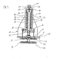
- Nachfolgend ist die Erfindung anhand eines Ausführungsbeispiels näher erläutert. In der Zeichnung zeigt:
- Fig. 1
- schematisch vereinfacht ein Absperrventil zum Verschließen einer Öffnung einer Tauchzelle eines Unterseeboots in perspektivisch, teilgeschnittener Ansicht,
- Fig. 2
- das Absperrventil nach
Fig. 1 in einer Draufsicht, und - Fig. 3
- das Absperrventil nach
Fig. 1 in einer Schnittansicht entlang der Schnittlinie II - II inFig. 2 . - Das in der Zeichnung dargestellte Absperrventil weist einen Flanschring 2 mit einer inneren Öffnung 4 auf. Mit diesem Flanschring 2 ist das Absperrventil an einer in der Zeichnung nicht dargestellten Tauchzelle eines Unterseeboots im Bereich einer an der Tauchzelle ausgebildeten Öffnung befestigt, wobei eine Stirnseite 6 (
Fig. 3 ) des Flanschringes 2 an der Außenseite der Tauchzelle aufliegt. Der Durchmesser der an dem Flanschring ausgebildeten Öffnung 4 ist geringer als der Durchmesser der an der Tauchzelle ausgebildeten Öffnung, sodass der Flanschring 2 mit einem an die Öffnung 4 angrenzenden Ringabschnitt die an der Tauchzelle ausgebildete Öffnung teilweise randseitig überdeckt und mit einem an den äußeren Rand des Flanschringes 2 angrenzenden Ringabschnitt auf der Außenseite der Tauchzelle aufliegt. - An diesem äußeren Ringabschnitt des Flanschringes 2 weist der Flanschring 2 um seinen Umfang gleichmäßig verteilt achtzehn Bohrungen 8 auf. Diese Bohrungen 8 dienen zur Aufnahme von Schrauben, mit denen der Flanschring 2 mit der Tauchzelle verschraubt ist.
- An einer von der Stirnseite 6 bzw. von der Tauchzelle abgewandten Stirnseite 10 sind über den Umfang des Flanschringes 2 jeweils in einem Winkel von 120° versetzt drei Halteelemente 12 angeordnet. Diese Halteelemente 12 erstrecken sich in einem an die Stirnseite 10 angrenzenden Abschnitt zunächst normal zu der Stirnseite 10. In einem sich daran anschließenden Abschnitt sind die Halteelemente 12 bogenförmig in Richtung des Zentrums des Flanschrings 2 gebogen, wobei in diesem Abschnitt eine von dem Flanschring 2 beabstandete, normal zur Stirnseite 10 des Flanschringes 2 ausgerichtete Endseite 14 der Halteelemente 12 in dem Lichtraumprofil der Öffnung 4 des Flanschringes 2 angeordnet ist. In Richtung des Flanschringes 2 an die Endseiten 14 der Halteelemente 12 anschließend ist an den Halteelementen 12 jeweils ein Absatz 16 ausgebildet.
- Die Halteelemente 12 bilden eine Halterung 18 für einen Hydraulikzylinder 20. Der Hydraulikzylinder 20 weist einen Zylinder 22 auf. An einem von dem Flanschring 2 abgewandten Ende des Zylinders 22 ist ein Vorsprung 24 ausgebildet, durch den eine gestufte Bohrung 26 in das Innere des Zylinders 22 führt. In der Bohrung 26 ist ein Anschlussteil 28 zum Anschluss einer nicht dargestellten hydraulischen Versorgungsleitung eingeschraubt. Das Anschlussteil 28 ist mit einer zentralen Bohrung 30 ausgestattet, über die Hydraulikflüssigkeit von der Versorgungsleitung in das Innere des Zylinders 22 geleitet werden kann.
- An einem dem Flanschring 2 zugewandten Ende des Zylinders 22, das offen ausgebildet ist, ist der Zylinder 22 an seiner Außenseite flanschartig erweitert. In dieses offene Ende des Zylinders 22 greift ein Endstück 32 ein. Das Endstück 32 weist an seinem außerhalb des Zylinders 22 befindlichen Ende ebenfalls eine flanschartige Erweiterung auf, die mit der flanschartigen Erweiterung des Zylinders 22 korrespondiert. Im Bereich dieser flanschartigen Erweiterung ist das Endstück 32 mit dem Zylinder 22 verschraubt.
- Der Hydraulikzylinder 20 ist umfangseitig mit den Halteelementen 22 im Bereich deren Endseiten 14 verbunden. Dabei stützen sich die flanschartige Erweiterung des Zylinders 22 und die flanschartige Erweiterung des Endstücks 32 an den an den Halteelementen 12 ausgebildeten Absätzen 16 ab.
- In dem Zylinder 22 ist ein in Längsrichtung des Zylinders 22 verschiebbarer Kolben 34 angeordnet. Der Kolben 34 teilt den Zylinder 22 in eine erste Zylinderkammer 36 und eine zweite Zylinderkamme 38. Der Zylinder 22 ist als doppelt wirkender Zylinder ausgebildet. Hierzu ist die Zylinderkammer 36 über das Anschlussteil 28 mit einem Hydraulikdruck beaufschlagbar. In einem an die flanschartige Erweiterung angrenzenden Abschnitt ist an dem Zylinder 22 ein aus der Zeichnung nicht ersichtliches zweites Anschlussteil angeordnet, über das Hydraulikflüssigkeit in die zweite Zylinderkammer 38 eingeleitet werden kann. An einer die zweite Zylinderkammer 38 begrenzenden Seite des Kolbens 34 ist eine Kolbenstange 40 ausgebildet. Ein von dem Kolben 34 abgewandter Endabschnitt der Kolbenstange 40 ist durch eine an dem Endstück 32 ausgebildete zentrale Öffnung geführt und ragt dort aus dem Zylinder 22 heraus.
- In der zweiten Zylinderkammer 38 ist eine Hülse 42 angeordnet, die die Kolbenstange 40 umgibt und an ihrem dem Kolben 34 zugewandten Ende eine ringförmig nach außen kragende Erweiterung aufweist, mit der die Hülse 42 an dem Kolben 34 anliegt. Des Weiteren ist in der Zylinderkammer 38 eine Schraubenfeder 44 um die Kolbenstange 40 und die Hülse 42 herum angeordnet. Die Schraubenfeder 44 stützt sich mit ihrem dem Kolben 34 zugewandten Ende an der nach außen kragenden Erweiterung der Hülse 42 und mit ihrem davon abgewandten Ende an dem Endstück 32 ab.
- An dem aus dem Zylinder 22 herausragenden Ende der Kolbenstange 40 ist ein Dichtungskörper 46 des Absperrventils befestigt. Bei diesem Dichtungskörper 46 handelt es sich um einen Ventilteller, der in einer Schließstellung des Absperrventils an der Stirnseite 6 des Flanschringes 2 zur Anlage kommt. Ein an der der Stirnseite 6 des Flanschringes 2 zugewandten Seite des Dichtungskörpers 46 angeordneter Dichtring 48 (
Fig. 1 ) dichtet dabei den Dichtungskörper 46 gegenüber dem Flanschring 2 gasdicht ab. -
Fig. 3 zeigt den Dichtungskörper 46 sowohl in einer Schließstellung A als auch in einer Öffnungsstellung B. In der Schließstellung A ist die Zylinderkammer 38 des Zylinders 22 mit Hydraulikflüssigkeit druckbeaufschlagt und hält so den Dichtungskörper 46 in der Schließstellung. Des Weiteren ist die in der Zylinderkammer 38 angeordnete Schraubenfeder 44 auf Druck vorgespannt, so dass die Schraubenfeder 44 ebenfalls eine Schließkraft auf den Kolben 34 und damit auf den Dichtungskörper 46 ausübt. Soll der Dichtungskörper 46 in die Öffnungsstellung B bewegt werden, wird Hydraulikflüssigkeit in die Zylinderkammer 36 geleitet und gleichzeitig die in der Zylinderkammer 38 befindliche Hydraulikflüssigkeit aus der Zylinderkammer 38 abgeleitet. Die in die Zylinderkammer 36 einströmende Hydraulikflüssigkeit drückt den Kolben 34 gegen die Federkraft der Schraubenfeder 44, die weiter auf Druck vorgespannt wird, in Richtung des Endstücks 32. Hierdurch löst sich der an der Kolbenstange 40 angeordnete Dichtungskörper 46 von dem von der Stirnseite 6 des Flanschrings 2 gebildeten Ventilsitz. Die Bewegung des Kolbens 34 in Richtung des Endstücks 32 wird dadurch begrenzt, dass das dem Endstück 32 zugewandte Ende der Hülse 42 an dem Endstück 32 zur Anlage kommt, wodurch eine Überlastung der Schraubenfeder 44 verhindert wird. Soll der Dichtungskörper 46 von der Öffnungsstellung B wieder zurück in die Schließstellung A zurückbewegt werden, wird wieder Hydraulikflüssigkeit in die Zylinderkammer 38 eingeleitet und die Hydraulikflüssigkeit aus der Zylinderkammer 36 abgeleitet. Sollte es aufgrund eines Defekts des Hydrauliksystems nicht möglich sein, die Zylinderkammer 38 mit Hydraulikflüssigkeit zu versorgen, drückt die auf Druck vorgespannte Schraubenfeder 44 den Kolben 34 in Einfahrrichtung, bis der Dichtungskörper 46 an der Stirnseite 6 des Flanschrings 2 in der Schließstellung gasdicht zur Anlage kommt. Da die Schraubenfeder 44 auch in der Schließstellung des Dichtungskörpers 46 eine gewisse Vorspannung aufweist, wird der Dichtungskörper 46 von der Schraubenfeder 44 in der Schließstellung gehalten. -
- 2
- - Flanschring
- 4
- - Öffnung
- 6
- - Stirnseite
- 8
- - Bohrung
- 10
- - Stirnseite
- 12
- - Halteelement
- 14
- - Endseite
- 16
- - Absatz
- 18
- - Halterung
- 20
- - Hydraulikzylinder
- 22
- - Zylinder
- 24
- - Vorsprung
- 26
- - Bohrung
- 28
- - Anschlussteil
- 30
- - Bohrung
- 32
- - Endstück
- 34
- - Kolben
- 36
- - Zylinderkammer
- 38
- - Zylinderkammer
- 40
- - Kolbenstange
- 42
- - Hülse
- 44
- - Schraubenfeder
- 46
- - Dichtungskörper
- 48
- - Dichtring
- A
- - Schließstellung
- B
- - Öffnungsstellung
Claims (9)
- Unterseeboot mit mindestens einer Tauchzelle, welche mindestens eine von einem Absperrventil verschlossene Öffnung aufweist, dadurch gekennzeichnet, dass das Absperrventil fluidisch ansteuerbar ausgebildet ist.
- Unterseeboot nach Anspruch 1, dadurch gekennzeichnet, dass ein Dichtungskörper des Absperrventils mit einer Kolbenstange (40) eines Hydraulikzylinders (20) bewegungsgekoppelt ist.
- Unterseeboot nach einem der vorangehenden Ansprüche, dadurch gekennzeichnet, dass das Absperrventil in Schließrichtung federvorgespannt ist.
- Unterseeboot nach einem der Ansprüche 2 oder 3, dadurch gekennzeichnet, dass der Hydraulikzylinder (20) ein doppeltwirkender Zylinder mit einer ersten, beim Ausfahrhub der Kolbenstange (40) druckbeaufschlagten Zylinderkammer (36) und einer zweiten, beim Einfahrhub der Kolbenstange (40) druckbeaufschlagten Zylinderkammer (38) ist.
- Unterseeboot nach Anspruch 4, dadurch gekennzeichnet, dass in der zweiten Zylinderkammer (38) des Hydraulikzylinders (20) eine Rückstellfeder angeordnet ist.
- Unterseeboot nach einem der Ansprüche 2 bis 5, dadurch gekennzeichnet, dass um die Kolbenstange (40) herum eine Hülse (42) angeordnet ist, welche den Ausfahrhub der Kolbenstange (40) begrenzt.
- Unterseeboot nach einem der vorangehenden Ansprüche, dadurch gekennzeichnet, dass das Absperrventil einen Flanschring (2) aufweist, welcher an dem Rand einer Öffnung der Tauchzelle aufliegend befestigt ist.
- Unterseeboot nach Anspruch 7, dadurch gekennzeichnet, dass die am Rand der Öffnung aufliegende Stirnfläche des Flanschrings (2) einen Ventilsitz bildet.
- Unterseeboot nach einem der Ansprüche 7 oder 8, dadurch gekennzeichnet, dass an einer von der Tauchzelle abgewandten Seite des Flanschrings (2) eine Halterung (18) für den Hydraulikzylinder (20) ausgebildet ist.
Applications Claiming Priority (1)
| Application Number | Priority Date | Filing Date | Title |
|---|---|---|---|
| DE102012208627A DE102012208627A1 (de) | 2012-05-23 | 2012-05-23 | Unterseeboot |
Publications (2)
| Publication Number | Publication Date |
|---|---|
| EP2666711A1 true EP2666711A1 (de) | 2013-11-27 |
| EP2666711B1 EP2666711B1 (de) | 2018-09-12 |
Family
ID=47900915
Family Applications (1)
| Application Number | Title | Priority Date | Filing Date |
|---|---|---|---|
| EP13159797.3A Active EP2666711B1 (de) | 2012-05-23 | 2013-03-18 | Unterseeboot |
Country Status (4)
| Country | Link |
|---|---|
| EP (1) | EP2666711B1 (de) |
| KR (1) | KR101496872B1 (de) |
| DE (1) | DE102012208627A1 (de) |
| ES (1) | ES2700023T3 (de) |
Families Citing this family (1)
| Publication number | Priority date | Publication date | Assignee | Title |
|---|---|---|---|---|
| KR102331407B1 (ko) * | 2020-07-27 | 2021-12-01 | 박원창 | 롤링이 저감된 낚시용 보트 |
Citations (4)
| Publication number | Priority date | Publication date | Assignee | Title |
|---|---|---|---|---|
| DE8608567U1 (de) * | 1986-03-29 | 1986-09-04 | Bopp & Reuther AG, 68305 Mannheim | Sicherheitsabsperrventil |
| EP1645501A1 (de) * | 2004-10-05 | 2006-04-12 | Howaldtswerke-Deutsche Werft GmbH | Anblasvorrichtung für ein Unterseeboot |
| EP2073090A2 (de) * | 2007-12-20 | 2009-06-24 | Howaldtswerke-Deutsche Werft GmbH | Gasventilanordnung |
| DE102008003982B3 (de) * | 2008-01-11 | 2009-07-02 | Gabler Maschinenbau Gmbh | Unterwasserfahrzeug |
Family Cites Families (1)
| Publication number | Priority date | Publication date | Assignee | Title |
|---|---|---|---|---|
| DE102007054781A1 (de) * | 2007-11-16 | 2009-05-28 | Howaldtswerke-Deutsche Werft Gmbh | Stromregelventil |
-
2012
- 2012-05-23 DE DE102012208627A patent/DE102012208627A1/de not_active Withdrawn
-
2013
- 2013-03-18 ES ES13159797T patent/ES2700023T3/es active Active
- 2013-03-18 EP EP13159797.3A patent/EP2666711B1/de active Active
- 2013-04-23 KR KR20130044657A patent/KR101496872B1/ko active Active
Patent Citations (4)
| Publication number | Priority date | Publication date | Assignee | Title |
|---|---|---|---|---|
| DE8608567U1 (de) * | 1986-03-29 | 1986-09-04 | Bopp & Reuther AG, 68305 Mannheim | Sicherheitsabsperrventil |
| EP1645501A1 (de) * | 2004-10-05 | 2006-04-12 | Howaldtswerke-Deutsche Werft GmbH | Anblasvorrichtung für ein Unterseeboot |
| EP2073090A2 (de) * | 2007-12-20 | 2009-06-24 | Howaldtswerke-Deutsche Werft GmbH | Gasventilanordnung |
| DE102008003982B3 (de) * | 2008-01-11 | 2009-07-02 | Gabler Maschinenbau Gmbh | Unterwasserfahrzeug |
Also Published As
| Publication number | Publication date |
|---|---|
| DE102012208627A1 (de) | 2013-11-28 |
| ES2700023T3 (es) | 2019-02-13 |
| KR101496872B1 (ko) | 2015-02-27 |
| KR20130131225A (ko) | 2013-12-03 |
| EP2666711B1 (de) | 2018-09-12 |
Similar Documents
| Publication | Publication Date | Title |
|---|---|---|
| DE102016115645B4 (de) | Batteriegehäuse | |
| EP0690253B1 (de) | Vorrichtung zum Abdichten von Absperrorganen | |
| DE3153338C2 (en) | Actuating device for a valve | |
| DE102015214256A1 (de) | Druckausgleichsvorrichtung | |
| DE102015106983A1 (de) | Fluidisches Sicherheitsventil und damit ausgestattete Batteriekomponente | |
| DE2744917B2 (de) | Sitzventil mit geradem Durchgang | |
| DE2806737C2 (de) | Ventil, insbesondere für Hochdruckdampf | |
| DE7516727U (de) | Kombiniertes schnellschluss- und regelventil | |
| EP3037679B1 (de) | Fluidbetriebener stellantrieb | |
| DE1918875A1 (de) | Schieberventil fuer Gase,Fluessigkeiten und Gas-Feststoff-Gemische | |
| EP2666711B1 (de) | Unterseeboot | |
| DE102004023255B3 (de) | Druckminderventil | |
| DE102014222210B3 (de) | Antrieb für eine Tür oder ein Fenster | |
| DE102010044632B4 (de) | Vorgesteuertes Mehrwegeventil | |
| EP2060837A2 (de) | Stromregelventil | |
| DE102008053930A1 (de) | Überdruckventil | |
| WO2014096458A1 (de) | Rohrabsperreinrichtung und vorrichtung zur notversorgung der in einem reaktorbehälter eines kernkraftwerks angeordneten brennstäbe mit kühlflüssigkeit mit einer solchen rohrabsperreinrichtung | |
| DE1951656C3 (de) | Full und Betätigungseinrichtung für (hydro )pneumatische Federn | |
| DE2420930C3 (de) | Abdichtungseinrichtung | |
| DE2107987A1 (de) | Kupplung fur Vielfachrohrleitungen | |
| DE102006033429B4 (de) | Druckbegrenzungsventil mit Ferneinstellung | |
| DE2837756A1 (de) | Ventil | |
| DE102022201230B4 (de) | Sicherheitsvorrichtung für ein linear betätigtes Prozessventil und System umfassend die Sicherheitsvorrichtung | |
| EP1039146A1 (de) | Hydraulisch entsperrbares Füllventil | |
| DE102012108379A1 (de) | Aktor für eine Ventileinheit zum Regeln eines Fluidflusses |
Legal Events
| Date | Code | Title | Description |
|---|---|---|---|
| PUAI | Public reference made under article 153(3) epc to a published international application that has entered the european phase |
Free format text: ORIGINAL CODE: 0009012 |
|
| AK | Designated contracting states |
Kind code of ref document: A1 Designated state(s): AL AT BE BG CH CY CZ DE DK EE ES FI FR GB GR HR HU IE IS IT LI LT LU LV MC MK MT NL NO PL PT RO RS SE SI SK SM TR |
|
| AX | Request for extension of the european patent |
Extension state: BA ME |
|
| 17P | Request for examination filed |
Effective date: 20140508 |
|
| RBV | Designated contracting states (corrected) |
Designated state(s): AL AT BE BG CH CY CZ DE DK EE ES FI FR GB GR HR HU IE IS IT LI LT LU LV MC MK MT NL NO PL PT RO RS SE SI SK SM TR |
|
| 17Q | First examination report despatched |
Effective date: 20160607 |
|
| REG | Reference to a national code |
Ref country code: DE Ref legal event code: R079 Ref document number: 502013011048 Country of ref document: DE Free format text: PREVIOUS MAIN CLASS: B63G0008220000 Ipc: F16K0031122000 |
|
| GRAP | Despatch of communication of intention to grant a patent |
Free format text: ORIGINAL CODE: EPIDOSNIGR1 |
|
| STAA | Information on the status of an ep patent application or granted ep patent |
Free format text: STATUS: GRANT OF PATENT IS INTENDED |
|
| RIC1 | Information provided on ipc code assigned before grant |
Ipc: F16K 31/122 20060101AFI20180326BHEP Ipc: B63G 8/22 20060101ALI20180326BHEP Ipc: F16K 1/12 20060101ALI20180326BHEP |
|
| INTG | Intention to grant announced |
Effective date: 20180425 |
|
| GRAJ | Information related to disapproval of communication of intention to grant by the applicant or resumption of examination proceedings by the epo deleted |
Free format text: ORIGINAL CODE: EPIDOSDIGR1 |
|
| GRAP | Despatch of communication of intention to grant a patent |
Free format text: ORIGINAL CODE: EPIDOSNIGR1 |
|
| GRAS | Grant fee paid |
Free format text: ORIGINAL CODE: EPIDOSNIGR3 |
|
| INTG | Intention to grant announced |
Effective date: 20180713 |
|
| GRAA | (expected) grant |
Free format text: ORIGINAL CODE: 0009210 |
|
| STAA | Information on the status of an ep patent application or granted ep patent |
Free format text: STATUS: THE PATENT HAS BEEN GRANTED |
|
| AK | Designated contracting states |
Kind code of ref document: B1 Designated state(s): AL AT BE BG CH CY CZ DE DK EE ES FI FR GB GR HR HU IE IS IT LI LT LU LV MC MK MT NL NO PL PT RO RS SE SI SK SM TR |
|
| REG | Reference to a national code |
Ref country code: GB Ref legal event code: FG4D Free format text: NOT ENGLISH |
|
| REG | Reference to a national code |
Ref country code: CH Ref legal event code: EP |
|
| REG | Reference to a national code |
Ref country code: IE Ref legal event code: FG4D Free format text: LANGUAGE OF EP DOCUMENT: GERMAN |
|
| REG | Reference to a national code |
Ref country code: DE Ref legal event code: R096 Ref document number: 502013011048 Country of ref document: DE |
|
| REG | Reference to a national code |
Ref country code: AT Ref legal event code: REF Ref document number: 1041000 Country of ref document: AT Kind code of ref document: T Effective date: 20181015 |
|
| REG | Reference to a national code |
Ref country code: DE Ref legal event code: R084 Ref document number: 502013011048 Country of ref document: DE |
|
| REG | Reference to a national code |
Ref country code: NL Ref legal event code: MP Effective date: 20180912 |
|
| REG | Reference to a national code |
Ref country code: LT Ref legal event code: MG4D |
|
| PG25 | Lapsed in a contracting state [announced via postgrant information from national office to epo] |
Ref country code: BG Free format text: LAPSE BECAUSE OF FAILURE TO SUBMIT A TRANSLATION OF THE DESCRIPTION OR TO PAY THE FEE WITHIN THE PRESCRIBED TIME-LIMIT Effective date: 20181212 Ref country code: SE Free format text: LAPSE BECAUSE OF FAILURE TO SUBMIT A TRANSLATION OF THE DESCRIPTION OR TO PAY THE FEE WITHIN THE PRESCRIBED TIME-LIMIT Effective date: 20180912 Ref country code: NO Free format text: LAPSE BECAUSE OF FAILURE TO SUBMIT A TRANSLATION OF THE DESCRIPTION OR TO PAY THE FEE WITHIN THE PRESCRIBED TIME-LIMIT Effective date: 20181212 Ref country code: GR Free format text: LAPSE BECAUSE OF FAILURE TO SUBMIT A TRANSLATION OF THE DESCRIPTION OR TO PAY THE FEE WITHIN THE PRESCRIBED TIME-LIMIT Effective date: 20181213 Ref country code: RS Free format text: LAPSE BECAUSE OF FAILURE TO SUBMIT A TRANSLATION OF THE DESCRIPTION OR TO PAY THE FEE WITHIN THE PRESCRIBED TIME-LIMIT Effective date: 20180912 Ref country code: LT Free format text: LAPSE BECAUSE OF FAILURE TO SUBMIT A TRANSLATION OF THE DESCRIPTION OR TO PAY THE FEE WITHIN THE PRESCRIBED TIME-LIMIT Effective date: 20180912 Ref country code: FI Free format text: LAPSE BECAUSE OF FAILURE TO SUBMIT A TRANSLATION OF THE DESCRIPTION OR TO PAY THE FEE WITHIN THE PRESCRIBED TIME-LIMIT Effective date: 20180912 |
|
| REG | Reference to a national code |
Ref country code: ES Ref legal event code: FG2A Ref document number: 2700023 Country of ref document: ES Kind code of ref document: T3 Effective date: 20190213 |
|
| PG25 | Lapsed in a contracting state [announced via postgrant information from national office to epo] |
Ref country code: LV Free format text: LAPSE BECAUSE OF FAILURE TO SUBMIT A TRANSLATION OF THE DESCRIPTION OR TO PAY THE FEE WITHIN THE PRESCRIBED TIME-LIMIT Effective date: 20180912 Ref country code: HR Free format text: LAPSE BECAUSE OF FAILURE TO SUBMIT A TRANSLATION OF THE DESCRIPTION OR TO PAY THE FEE WITHIN THE PRESCRIBED TIME-LIMIT Effective date: 20180912 Ref country code: AL Free format text: LAPSE BECAUSE OF FAILURE TO SUBMIT A TRANSLATION OF THE DESCRIPTION OR TO PAY THE FEE WITHIN THE PRESCRIBED TIME-LIMIT Effective date: 20180912 |
|
| PG25 | Lapsed in a contracting state [announced via postgrant information from national office to epo] |
Ref country code: EE Free format text: LAPSE BECAUSE OF FAILURE TO SUBMIT A TRANSLATION OF THE DESCRIPTION OR TO PAY THE FEE WITHIN THE PRESCRIBED TIME-LIMIT Effective date: 20180912 Ref country code: CZ Free format text: LAPSE BECAUSE OF FAILURE TO SUBMIT A TRANSLATION OF THE DESCRIPTION OR TO PAY THE FEE WITHIN THE PRESCRIBED TIME-LIMIT Effective date: 20180912 Ref country code: NL Free format text: LAPSE BECAUSE OF FAILURE TO SUBMIT A TRANSLATION OF THE DESCRIPTION OR TO PAY THE FEE WITHIN THE PRESCRIBED TIME-LIMIT Effective date: 20180912 Ref country code: RO Free format text: LAPSE BECAUSE OF FAILURE TO SUBMIT A TRANSLATION OF THE DESCRIPTION OR TO PAY THE FEE WITHIN THE PRESCRIBED TIME-LIMIT Effective date: 20180912 Ref country code: IS Free format text: LAPSE BECAUSE OF FAILURE TO SUBMIT A TRANSLATION OF THE DESCRIPTION OR TO PAY THE FEE WITHIN THE PRESCRIBED TIME-LIMIT Effective date: 20190112 Ref country code: PL Free format text: LAPSE BECAUSE OF FAILURE TO SUBMIT A TRANSLATION OF THE DESCRIPTION OR TO PAY THE FEE WITHIN THE PRESCRIBED TIME-LIMIT Effective date: 20180912 |
|
| PG25 | Lapsed in a contracting state [announced via postgrant information from national office to epo] |
Ref country code: SK Free format text: LAPSE BECAUSE OF FAILURE TO SUBMIT A TRANSLATION OF THE DESCRIPTION OR TO PAY THE FEE WITHIN THE PRESCRIBED TIME-LIMIT Effective date: 20180912 Ref country code: PT Free format text: LAPSE BECAUSE OF FAILURE TO SUBMIT A TRANSLATION OF THE DESCRIPTION OR TO PAY THE FEE WITHIN THE PRESCRIBED TIME-LIMIT Effective date: 20190112 Ref country code: SM Free format text: LAPSE BECAUSE OF FAILURE TO SUBMIT A TRANSLATION OF THE DESCRIPTION OR TO PAY THE FEE WITHIN THE PRESCRIBED TIME-LIMIT Effective date: 20180912 |
|
| REG | Reference to a national code |
Ref country code: DE Ref legal event code: R097 Ref document number: 502013011048 Country of ref document: DE |
|
| PLBE | No opposition filed within time limit |
Free format text: ORIGINAL CODE: 0009261 |
|
| STAA | Information on the status of an ep patent application or granted ep patent |
Free format text: STATUS: NO OPPOSITION FILED WITHIN TIME LIMIT |
|
| PG25 | Lapsed in a contracting state [announced via postgrant information from national office to epo] |
Ref country code: DK Free format text: LAPSE BECAUSE OF FAILURE TO SUBMIT A TRANSLATION OF THE DESCRIPTION OR TO PAY THE FEE WITHIN THE PRESCRIBED TIME-LIMIT Effective date: 20180912 |
|
| 26N | No opposition filed |
Effective date: 20190613 |
|
| PG25 | Lapsed in a contracting state [announced via postgrant information from national office to epo] |
Ref country code: SI Free format text: LAPSE BECAUSE OF FAILURE TO SUBMIT A TRANSLATION OF THE DESCRIPTION OR TO PAY THE FEE WITHIN THE PRESCRIBED TIME-LIMIT Effective date: 20180912 |
|
| REG | Reference to a national code |
Ref country code: DE Ref legal event code: R081 Ref document number: 502013011048 Country of ref document: DE Owner name: THYSSENKRUPP MARINE SYSTEMS GMBH, DE Free format text: FORMER OWNER: THYSSENKRUPP MARINE SYSTEMS GMBH, 24143 KIEL, DE |
|
| PG25 | Lapsed in a contracting state [announced via postgrant information from national office to epo] |
Ref country code: MC Free format text: LAPSE BECAUSE OF FAILURE TO SUBMIT A TRANSLATION OF THE DESCRIPTION OR TO PAY THE FEE WITHIN THE PRESCRIBED TIME-LIMIT Effective date: 20180912 |
|
| REG | Reference to a national code |
Ref country code: CH Ref legal event code: PL |
|
| PG25 | Lapsed in a contracting state [announced via postgrant information from national office to epo] |
Ref country code: LU Free format text: LAPSE BECAUSE OF NON-PAYMENT OF DUE FEES Effective date: 20190318 |
|
| REG | Reference to a national code |
Ref country code: BE Ref legal event code: MM Effective date: 20190331 |
|
| PG25 | Lapsed in a contracting state [announced via postgrant information from national office to epo] |
Ref country code: CH Free format text: LAPSE BECAUSE OF NON-PAYMENT OF DUE FEES Effective date: 20190331 Ref country code: LI Free format text: LAPSE BECAUSE OF NON-PAYMENT OF DUE FEES Effective date: 20190331 Ref country code: IE Free format text: LAPSE BECAUSE OF NON-PAYMENT OF DUE FEES Effective date: 20190318 |
|
| PG25 | Lapsed in a contracting state [announced via postgrant information from national office to epo] |
Ref country code: BE Free format text: LAPSE BECAUSE OF NON-PAYMENT OF DUE FEES Effective date: 20190331 |
|
| PG25 | Lapsed in a contracting state [announced via postgrant information from national office to epo] |
Ref country code: TR Free format text: LAPSE BECAUSE OF FAILURE TO SUBMIT A TRANSLATION OF THE DESCRIPTION OR TO PAY THE FEE WITHIN THE PRESCRIBED TIME-LIMIT Effective date: 20180912 |
|
| PG25 | Lapsed in a contracting state [announced via postgrant information from national office to epo] |
Ref country code: MT Free format text: LAPSE BECAUSE OF FAILURE TO SUBMIT A TRANSLATION OF THE DESCRIPTION OR TO PAY THE FEE WITHIN THE PRESCRIBED TIME-LIMIT Effective date: 20180912 |
|
| REG | Reference to a national code |
Ref country code: AT Ref legal event code: MM01 Ref document number: 1041000 Country of ref document: AT Kind code of ref document: T Effective date: 20190318 |
|
| PG25 | Lapsed in a contracting state [announced via postgrant information from national office to epo] |
Ref country code: AT Free format text: LAPSE BECAUSE OF NON-PAYMENT OF DUE FEES Effective date: 20190318 |
|
| PG25 | Lapsed in a contracting state [announced via postgrant information from national office to epo] |
Ref country code: CY Free format text: LAPSE BECAUSE OF FAILURE TO SUBMIT A TRANSLATION OF THE DESCRIPTION OR TO PAY THE FEE WITHIN THE PRESCRIBED TIME-LIMIT Effective date: 20180912 |
|
| PG25 | Lapsed in a contracting state [announced via postgrant information from national office to epo] |
Ref country code: HU Free format text: LAPSE BECAUSE OF FAILURE TO SUBMIT A TRANSLATION OF THE DESCRIPTION OR TO PAY THE FEE WITHIN THE PRESCRIBED TIME-LIMIT; INVALID AB INITIO Effective date: 20130318 |
|
| PG25 | Lapsed in a contracting state [announced via postgrant information from national office to epo] |
Ref country code: MK Free format text: LAPSE BECAUSE OF FAILURE TO SUBMIT A TRANSLATION OF THE DESCRIPTION OR TO PAY THE FEE WITHIN THE PRESCRIBED TIME-LIMIT Effective date: 20180912 |
|
| PGFP | Annual fee paid to national office [announced via postgrant information from national office to epo] |
Ref country code: ES Payment date: 20250428 Year of fee payment: 13 |
|
| REG | Reference to a national code |
Ref country code: DE Ref legal event code: R081 Ref document number: 502013011048 Country of ref document: DE Owner name: TKMS GMBH, DE Free format text: FORMER OWNER: THYSSENKRUPP MARINE SYSTEMS GMBH, 24143 KIEL, DE |
|
| PGFP | Annual fee paid to national office [announced via postgrant information from national office to epo] |
Ref country code: GB Payment date: 20260324 Year of fee payment: 14 |
|
| PGFP | Annual fee paid to national office [announced via postgrant information from national office to epo] |
Ref country code: DE Payment date: 20260319 Year of fee payment: 14 |
|
| PGFP | Annual fee paid to national office [announced via postgrant information from national office to epo] |
Ref country code: IT Payment date: 20260324 Year of fee payment: 14 |
|
| PGFP | Annual fee paid to national office [announced via postgrant information from national office to epo] |
Ref country code: FR Payment date: 20260320 Year of fee payment: 14 |