EP2666519A2 - Feuerlöscher mit Behältern für Zusatzstoffe - Google Patents
Feuerlöscher mit Behältern für Zusatzstoffe Download PDFInfo
- Publication number
- EP2666519A2 EP2666519A2 EP13179461.2A EP13179461A EP2666519A2 EP 2666519 A2 EP2666519 A2 EP 2666519A2 EP 13179461 A EP13179461 A EP 13179461A EP 2666519 A2 EP2666519 A2 EP 2666519A2
- Authority
- EP
- European Patent Office
- Prior art keywords
- cartridge
- tanks
- tank
- side wall
- extinguisher
- Prior art date
- Legal status (The legal status is an assumption and is not a legal conclusion. Google has not performed a legal analysis and makes no representation as to the accuracy of the status listed.)
- Withdrawn
Links
Images



Classifications
-
- A—HUMAN NECESSITIES
- A62—LIFE-SAVING; FIRE-FIGHTING
- A62C—FIRE-FIGHTING
- A62C13/00—Portable extinguishers which are permanently pressurised or pressurised immediately before use
- A62C13/66—Portable extinguishers which are permanently pressurised or pressurised immediately before use with extinguishing material and pressure gas being stored in separate containers
-
- A—HUMAN NECESSITIES
- A62—LIFE-SAVING; FIRE-FIGHTING
- A62C—FIRE-FIGHTING
- A62C5/00—Making of fire-extinguishing materials immediately before use
- A62C5/002—Apparatus for mixing extinguishants with water
-
- A—HUMAN NECESSITIES
- A62—LIFE-SAVING; FIRE-FIGHTING
- A62C—FIRE-FIGHTING
- A62C35/00—Permanently-installed equipment
- A62C35/02—Permanently-installed equipment with containers for delivering the extinguishing substance
- A62C35/023—Permanently-installed equipment with containers for delivering the extinguishing substance the extinguishing material being expelled by compressed gas, taken from storage tanks, or by generating a pressure gas
Definitions
- the invention relates to the field of fire extinguishers. More particularly, the invention relates to an extinguisher comprising a cylinder adapted to contain a fire extinguisher, means for releasing the extinguishing product from the cylinder and comprising at least one compressed gas cartridge, at least two tanks each capable of containing at least one additive product, and means for releasing the at least one additive product from the at least two reservoirs and for mixing it with the extinguishing product during the release of the extinguishing product.
- the invention also relates to fire extinguisher cartridges and the use of such cartridges.
- extinguishers exist on the market. They can be classified according to the type of extinguishing product they use: water extinguisher, foam, powder or gas (carbon dioxide). The use of one type of extinguisher over another depends essentially on the burning material. Water extinguishers are used for class A fires, foam and gas fire extinguishers for class A or B fires. Powder fire extinguishers can be used for class A and B, AB and C, or D. The formulations present in the fire extinguisher also vary depending on the type of fire extinguisher.
- Known extinguishers comprise a reservoir, for example a cartridge, containing all the additive products. This one is usually arranged inside the bottle.
- fire extinguishers containing several additive chambers have been described.
- an extinguisher comprising a percussion head and a protective tube in which is arranged a gas capsule and two additive receiving chambers permanently attached to the protection tube.
- the additive receiving chambers are not accessible independently by the user.
- EP 1 935 458 a fire extinguisher consisting of two outer tanks attached to the body of the fire extinguisher cylinder. This configuration requires the use of numerous connectors to connect the additive compartments, the compressed gas cartridge and the interior of the cylinder.
- Additive cartridges in fire extinguishers have an expiry date. In the majority of cases, they have not been used before this expiry date and must therefore be changed. The unused cartridges are burned without establishing a recycling scheme or specific treatment of the additives present in said cartridge. However, some of said additives are polluting or dangerous for the environment. The recycling of these known cartridges, or their contents, is not easy considering their configuration or their location vis-à-vis the bottle extinguisher. The change of these cartridges can therefore be dangerous and expensive. There is a need for an extinguisher for better recycling of the cartridges containing the additives.
- the invention proposes to overcome the disadvantages mentioned above while retaining the advantages of known cartridges.
- the present invention provides an extinguisher comprising at least two tanks each capable of containing at least one additive product and means for releasing the at least one additive product from each of the at least two tanks, and characterized in that at least one of the tanks is removable from the fire extinguisher.
- the term "at least one "tank” is considered to include, in particular, the terms “one or more tanks” and "a plurality of tanks”.
- said at least two tanks are removable relative to the fire extinguisher.
- the term "removable from fire extinguisher” means that the tanks may be detached or removed from the fire extinguisher to form a separate, separate or disjointed element from the fire extinguisher.
- At least two tanks is considered to include, in particular, the terms “two or more tanks” and "a plurality of tanks".
- the presence of several reservoirs each able to contain one or more additives makes it possible to partition the additives in the different reservoirs.
- the different tanks can be filled according to the subsequent purpose sought from a point of view of the recycling or treatment of said additives.
- one or more additives classified as highly polluting for the environment and which can be treated or recycled separately according to the same procedure may be placed inside a first reservoir.
- a second tank may for example contain one or more non-polluting additives and not requiring treatment or recycling.
- the additives in the different tanks can also be separated according to their chemical structure, for example separating the fluorinated additives and the non-fluorinated additives, or separating the long-chain hydrocarbons from the shorter-chain hydrocarbons.
- the presence of tanks having a removable relative to the fire extinguisher makes it possible to extract or remove the tank or tanks from the extinguisher and to treat them individually according to a precise recycling scheme.
- the tanks containing the additive products can thus be directly accessible to the user responsible for controlling the proper functioning of the fire extinguisher.
- the at least two reservoirs are disposed inside the cylinder.
- the arrangement of the tanks inside the cylinder facilitates their use in several types of fire extinguisher. This embodiment avoids the use of complex connection between the tank and the extinguishant product.
- said at least two tanks are disjoint.
- tanks can be treated or recycled independently one of the other. For example, if one of the tanks contains an additive product with an expiry date that is shorter than that of the additive product contained in the second tank, only the tank with expired contents may be removed from the fire extinguisher.
- the at least two tanks are provided with means to be interconnected by their end or by their side wall.
- the tanks can be interconnected and grouped in a small space of the fire extinguisher.
- the mixture between the additives and the extinguishing product will be more homogeneous.
- this embodiment will facilitate the gripping of all the tanks and their subsequent separation.
- At least one of the tanks has a side wall connected to another tank, preferably to the side wall of another tank, more preferably at least one of the tanks has a side wall at least partly common with a side wall of another tank.
- the invention relates to an extinguisher cartridge, said cartridge comprising a plurality of reservoirs, said reservoirs comprising one or more additives capable of improving the properties of the extinguishing product.
- at least one of the tanks is removable relative to the cartridge.
- the term "removable relative to the cartridge” means that the reservoir can be detached or removed from the cartridge to form a separate, separate or disjoint element of said cartridge.
- said tanks are fixed relative to the cartridge.
- said tanks may have a side wall or upper at least partly common to that of the cartridge. This alternative configuration also makes it possible to provide separate tanks whose lower opening is accessible directly to a user wishing to remove or modify the contents of the tanks or to fill them with a solution of freshly prepared additive products.
- the invention relates to the use of said cartridge in a fire extinguisher.
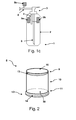
- Fig. 1a-cr schematically represent transverse sections of extinguishers according to particular modes of configuration of the present invention.
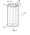
- the Fig. 2 is a schematic view of a reservoir according to an embodiment of the present invention.
- the Fig. 3 represents a schematic view of two tanks assembled with each other according to an embodiment of the present invention.
- the Fig. 4 is a schematic view of a cartridge comprising two reservoirs according to a particular embodiment of the present invention.
- the Fig. 5 is a schematic view of a cartridge comprising four tanks according to a particular embodiment of the present invention.
- the Fig. 6 is a schematic view of a cartridge comprising two reservoirs according to a particular embodiment of the present invention.
- the present invention relates to a fire extinguisher.
- the D.1a schematically shows a cross section of an embodiment of a fire extinguisher according to the present invention.
- the fire extinguisher 1 comprises a cylinder 2 which can be filled with an extinguishing product such as, for example, water.
- the extinguisher 1 also includes means for releasing the extinguishant product out of the cylinder.
- the cylinder is surmounted by an ejection head 3 connected to a tube 6 immersed in the cylinder 2.
- a container of compressed propellant gas 4 is connected to the ejection head 3.
- the fire extinguisher also comprises two tanks according to the invention. 'invention 5a and 5b arranged inside the cylinder 2.
- the two tanks are able to contain one or more additives to improve the extinguishing agent extinguishing properties. Both tanks are removable from the fire extinguisher.
- the two tanks are disjoint. These can be maintained by fastening means (not shown on the Fig. 1a ), for example by means of a hook, to the cylinder 2 or to another element of the fire extinguisher.
- the two tanks can also be movable relative to the cylinder 2. Indeed, the two tanks can move inside the cylinder 2.
- the fastening means stabilizes the tank inside the cylinder 2 all by promoting its subsequent extraction.
- the user To use the extinguisher 1, the user must actuate the ejection head 3 of the fire extinguisher 1 to allow the release of the propellant inside the cylinder 2. Under the effect of the differential pressure, means allow the release of the at least one additive product from the first tank 5a and the at least one additive product of the second tank 5b. The additive products are thus mixed with the extinguishing product. This mixture is then ejected by the tube 6 to the ejection head 3. If the fire extinguisher is not used, the two tanks 5a and 5b can be easily extracted from the cylinder 2, and thus the fire extinguisher, for be replaced by new tanks containing for example a new formulation.
- a tank 5a can also be extracted by the user and replaced by a freshly prepared solution.
- the removable nature of the two tanks allows the easy recycling of these and their contents.
- This embodiment of the invention also makes it easy to adapt existing fire extinguishers and does not require the replacement or modification of the connectors of extinguishing fire extinguishers.
- the means allowing the release of the at least one additive from the first tank 5a and the second tank 5b may for example be sealing means arranged on the corresponding tanks which, under a predetermined differential pressure, allow the release of the additives.
- the differential pressure is usually between 0.2 MPa and 0.8 MPa, preferably between 0.3 MPa and 0.5 MPa.
- said sealing means may independently be a cap capable of breaking or a valve capable of opening at a differential pressure of between 0.2 MPa and 0.8 MPa, preferably between 0.3 MPa and 0, 5 MPa.
- Said at least two tanks 5a, 5b can be disposed outside and / or inside the cylinder 2 of said extinguisher 1.
- the Fig. 1 b represents a cross section of a fire extinguisher according to another particular embodiment of the present invention in which two tanks 5a, 5b are arranged outside the cylinder 2.
- a discharge pipe extinguishing product 8 is connected to the tanks 5a and 5b assembled with each other.
- the Fig. 1 C represents a cross section of a fire extinguisher according to another particular embodiment of the present invention in which a tank 5c is connected to the discharge pipe 8 of the ejection head 3, and two tanks 5a and 5b are arranged at the inside the cylinder 2.
- At least one of the tanks 5 is disposed inside the cylinder 2. More preferably, said at least two tanks 5 are arranged inside the cylinder 2.
- said at least two reservoirs 5a and 5b are provided with means for being connected together removably. This may, for example, facilitate their arrangement inside the cylinder 2.
- Said means may for example be a thread, a tapping, a male-female notch system or a clip.
- the Fig. 2 is a schematic view of a reservoir 5 according to this preferred embodiment of the present invention. This comprises an upper part 9, a side wall 10 and a lower part 11.
- the lower part 11 of the tank 5 comprises a lower opening 30.
- the lower part 11 of the tank has a fastening means 12 for connecting said tank 5 to another tank.
- Said fastening means is a tapping 14.
- the upper part 9 of the tank comprises a thread 13.
- the tapping 14 makes it possible to assemble the tank 5 with a second tank having a thread on its upper part.
- Said at least two tanks may also be interconnected by their end or their side wall.
- the term "end" means the upper part and the lower part of a tank.
- the bottom wall of a first tank can be connected to the upper part of a second tank.
- the lower part of the second tank or the upper part of the first tank can be connected respectively to the upper or lower part of a third tank.
- the lower part 11 of a single tank can be immersed in the fire extinguishant.
- FIG. 3 is a schematic view of two tanks 5a and 5b joined together by their side wall 10 through a fastening means represented by a male-female notch system 12a, 12b.
- each tank comprises a male notch 12a and a female notch 12b for assembling the two tanks.
- the notches can be located indifferently over the entire surface of the side wall.
- This embodiment also has the advantage of allowing the additives to be released simultaneously and not sequentially in the extinguishing product.
- the tanks 5a and 5b may optionally comprise a second fixing means on their upper and / or lower part, for example a thread allowing the assembly of other tanks above and / or below them.
- Said tanks are provided with a lower sealing means and a higher sealing means.
- the tanks 5a, 5b have a sealing means 15a, 15b on their lower part and a sealing means 16a, 16b on their upper part.
- the lower sealing means 15a, 15b can be adapted to close the lower opening 30 of the tank 5.
- Said lower sealing means 15a, 15b are for example caps. These may be aluminum, polyethylene or any other polymer capable of forming a polymeric film that can rupture under a differential pressure of, for example, between 0.2 MPa and 0.8 MPa, preferably between 0.3 MPa and 0. , 5MPa to allow the release of additive products.
- Said lower sealing means can be configured to allow for the replacement of the additive products of the tank 5.
- the user can remove the lid, change the solution of the additive products and then deposit a new cap to close the lower opening 30 of the tank 5
- the upper sealing means 16a and 16b are not configured to break below the aforesaid differential pressure range.
- Said upper sealing means 16a, 16b may be made of the same material as the side wall of said tank, such as for example high-density polyethylene (HDPE) recycled or not.
- said lower and upper sealing means 15, 16 may be configured to allow the release of additive products.
- the sealing means may be adapted according to the assembly of said tanks.
- the tank located above may contain an upper sealing means configured to not allow the release of additive products in contrast to the lower sealing means of said tank located above and other sealing means of the other tanks.
- the lower sealing means is configured to allow the release of the additive products.
- At least one reservoir is disposed inside a cartridge 20 and thus forming at least one separate compartment inside said cartridge 20.
- Said cartridge 20 comprises a side wall 22, an upper part 21 and a lower part 23.
- the lower part 23 of the cartridge 20 is the one that is in contact with the liquid of the bottle 2 of the extinguisher 1 or that connected to the pipe exhaust pipe 8 of the fire extinguisher 1.
- Said at least one tank 5 is removable relative to the cartridge 20.
- at least two tanks 5a, 5b are disposed inside said cartridge 20 thus forming a plurality of compartments inside of it. Each tank can thus be arranged independently of others.
- said at least two tanks are removable relative to the cartridge 20.
- the lower opening 30 of each tank can be accessed directly. Thus, a user can easily remove or change the additive product contained in the tank 5.
- the Fig. 6 is a schematic view of a cartridge 20 comprising two reservoirs 5a and 5b.
- the tanks 5a and 5b are removable relative to the cartridge 20.
- the tanks 5a and 5b can be movable with respect to the cartridge 20. These are preferably locked inside the cartridge 20 by the cartridge 20.
- intermediate blocking means 25 placed for example on the lower portion 23 of said cartridge 20.
- the reservoir blocking means 5a is not shown. A modification of the positioning of said blocking means 25 makes it possible to remove the tanks 5a and 5b.
- the withdrawal of a reservoir is independent of the withdrawal of the other reservoir present in the cartridge. Subsequent treatment of the tank is thus facilitated.
- At least one of the tanks 5 disposed inside the cartridge 20 has a wall at least partly common with a wall of said cartridge 20.
- said at least one of the reservoirs 5 and said cartridge 20 have their side wall or upper at least partly common.
- said at least one of the tanks 5 and said cartridge 20 have their upper part and their side wall at least partly common.
- At least a portion of the side wall of a first reservoir 5a disposed within the cartridge 20 is common with the side wall of a second reservoir 5b disposed within the cartridge 20.
- a means separation is thus formed between said first and second tanks by the common part of their side wall.
- said at least two tanks 5 may have a side wall at least partly common with that of said cartridge 20 and at least partly in common with a wall at least one other tank 5 present in the cartridge 20.
- each tank 5 disposed inside the cartridge 20 has a side wall partly common with that of said cartridge 20 and partly common with a side wall of at least one other tank disposed within the cartridge 20. In this case, the lower opening 30 of each tank 5 can be accessed directly.
- the mixture between the additive products of each tank and the extinguishing product will be simultaneous.
- said cartridge 20 is provided with a lower sealing means 27 disposed on its lower part 23.
- Said lower sealing means 27 of said cartridge may be partly or entirely common with said closure means lower seal of at least one tank or plurality of tanks.
- said lower sealing means 27 of said cartridge 20 is common with said lower sealing means of the plurality of reservoirs 5 disposed within the cartridge.
- said lower sealing means 27 is a means for closing at least one tank 5 or the plurality of tanks 5.
- Said lower sealing means of the cartridge 20 and the tanks 5 may be a lid as described previously.
- the upper sealing means 28 of the cartridge 20 is configured not to allow the release of the additive products.
- the extinguishing products currently used are compositions of several derivatives which may comprise, in particular, floating film forming agents (AFFF).
- AFFF floating film forming agents
- the global production of AFFF represents several million tons annually.
- floating film-forming agents may contain hydrocarbon surfactants (ionic, nonionic or amphoteric), fluorinated or perfluorinated surfactants, glycol ether derivatives, and optionally other additives, for example biocides, anti-corrosive agents, or rheology agents.
- hydrocarbon surfactants ionic, nonionic or amphoteric
- fluorinated or perfluorinated surfactants ionic, nonionic or amphoteric
- glycol ether derivatives glycol ether derivatives
- optionally other additives for example biocides, anti-corrosive agents, or rheology agents.
- At least one of the reservoirs is capable of containing or contains a floating film forming agent (AFFF) composition.
- AFFF floating film forming agent
- at least one of the reservoirs is capable of containing or contains one or more fluorinated or perfluorinated surfactant (s).
- the extinguisher is a water or foam extinguisher.
- the invention relates to a cartridge extinguisher 1 characterized in that it comprises a plurality of reservoirs 5, said reservoirs 5 each being capable of containing one or more additives capable of improving the properties of an extinguishing product .
- the cartridge is located inside the cylinder 2.
- the cartridge 20 may be movable relative to the extinguisher or removable relative thereto.
- At least one of said reservoirs 5 is removable relative to the cartridge 20.
- the cartridge 20 may be provided with a means 25 for blocking at least one reservoir of said plurality of reservoirs 5 to block said at least one reservoir within the cartridge 20.
- the cartridge 20 may contain at least two removable reservoirs relative thereto. Said at least two tanks can be connected together removably.
- Cartridge 20 is also described in detail above with reference to Fig. 2-3 and 6 .
- At least one of said reservoirs 5 is fixed with respect to the cartridge 20.
- it may comprise a wall at least partly common to that of the cartridge 20.
- At least one of said reservoirs 5 may have a wall at least partly common with a wall of another tank disposed in the cartridge 20.
- at least one of said tanks 5 may have a side wall at least partly common with a side wall of another tank disposed in the cartridge 20.
- the lower opening 30 of said at least tank 5 can be accessed directly. For example, when renewing the cartridge, if it contains several mobile or removable tanks, the user can remove if necessary mobile or removable tanks and have direct access to the lower opening of the fixed tank and therefore to the contents of it. If the cartridge 20 contains several fixed reservoirs, these can be juxtaposed or partially superimposed to maintain direct access to the lower opening 30.
- the cartridge 20 contains a plurality of reservoirs 5 of which at least one of the reservoirs has a side wall at least partly common with a side wall of at least one other reservoir 5 disposed in the cartridge 20.
- the cartridge 20 may also contain at least two tanks having a side wall at least partly common with a side wall of another tank disposed inside the cartridge 20.
- said at least one of the tanks 5 may have a wall at least partly common with a wall of the cartridge 20.
- at least two of the reservoirs 5 have a wall common to that of the cartridge 20.
- At least a part of the side wall or top of the one of the tanks 5 may be partly common with a side wall or top of said cartridge 20.
- at least one of the tanks 5a, 5b has a side wall at least partly common with a e side wall of the cartridge 20 and at least partly common with a side wall of at least one other reservoir 5 disposed inside the cartridge 20.
- each reservoir 5 disposed inside the cartridge 20 has a side wall at least partly in common with a side wall of at least one other reservoir disposed inside the cartridge 20.
- Each reservoir 5 disposed inside the cartridge 20 may also have a side wall at least partly common with a side wall of said cartridge 20.
- Fig. 4 is a schematic view of a cartridge 20 comprising two reservoirs according to a particular embodiment of the present invention.
- the cartridge 20 comprises an upper portion 21, a side wall 22 and a lower portion 23.
- the cartridge 20 comprises two reservoirs 5a and 5b.
- the side walls and the lower part of the tanks 5a and 5b are respectively partly in common with the side wall 22 and the lower part 23 of the cartridge 20.
- the side wall of the tank 5a is partly in common with the side wall of the tank. tank 5b and thus forms a means of separation 24 between the two tanks.
- the separation means 24 is a polymer membrane.
- the membrane may consist of HDPE recycled or not, or any other material ensuring the tightness of the tanks between them and do not interact with the additives.
- This embodiment of the cartridge can be easily prepared by extrusion or injection, limiting production costs. In addition, this embodiment allows a parallel or simultaneous release of the additives contained in the tanks.
- the upper portion 21 of the cartridge 20 may be surmounted by a gripping ring. This can be replaced by any other means likely to allow gripping of the cartridge.
- FIG. 5 Another embodiment of the cartridge 20 according to the invention is detailed in the Fig. 5 .
- the reservoir 5a has its side wall partly in common with that of the cartridge 20 and partly common with that of the reservoir 5b and 5d.
- the four tanks are separated from each other by the separation means 24a and 24b.
- Said lower sealing means 27 of said cartridge 20 is common with said lower sealing means 15 of the plurality of reservoirs 5 disposed within the cartridge.
- said lower sealing means is a cap as described above.
- At least one of the tanks 5 of the cartridge 20 is able to contain or contains a composition of floating film forming agents (AFFF).
- AFFF floating film forming agents
- at least one of the reservoirs 5 is capable of containing or contains one or more fluorinated or perfluorinated surfactant (s).
- the invention relates to the use of one or more cartridge (s) according to the invention in a fire extinguisher.
- the cartridge (s) can be placed inside the cylinder 2 of the fire extinguisher 1 and / or on the ejection head 3 of the fire extinguisher 1.
- the cartridge 20 is placed in the bottle 2 of the extinguisher 1
- the lower part 23 of said cartridge 20 is immersed in the extinguishing product filling said cylinder 2.
- the lower part 23 of said cartridge is connected with the ejection pipe 8 of the fire extinguisher.
- the extinguisher may be a water or foam extinguisher.
- One or more cartridges may also be used to distribute in the plurality of tanks 5a, 5b of said cartridge 20, one or more additives to improve the properties of a fire extinguishant.
- a fire extinguisher 1 comprising a cylinder 2 capable of containing an extinguishing product, and means for releasing the extinguishing product from the cylinder and comprising at least one compressed gas cartridge, at at least two tanks 5a, 5b each able to contain at least one additive product, means for releasing the at least one additive product from each of the at least two tanks 5a, 5b and to mix them with the extinguishing product during the release of the product extinguisher, and characterized in that at least one of the tanks 5a, 5b is removable relative to the fire extinguisher 1.
Landscapes
- Health & Medical Sciences (AREA)
- Public Health (AREA)
- Business, Economics & Management (AREA)
- Emergency Management (AREA)
- Containers And Packaging Bodies Having A Special Means To Remove Contents (AREA)
- Fire-Extinguishing Compositions (AREA)
- Filling Or Discharging Of Gas Storage Vessels (AREA)
Applications Claiming Priority (2)
| Application Number | Priority Date | Filing Date | Title |
|---|---|---|---|
| BE2010/0529A BE1019473A3 (fr) | 2010-09-06 | 2010-09-06 | Extincteur a reservoirs pour additifs. |
| EP11180221.1A EP2425876B1 (de) | 2010-09-06 | 2011-09-06 | Feuerlöscher mit Behältern für Additive |
Related Parent Applications (2)
| Application Number | Title | Priority Date | Filing Date |
|---|---|---|---|
| EP11180221.1 Division | 2011-09-06 | ||
| EP11180221.1A Division-Into EP2425876B1 (de) | 2010-09-06 | 2011-09-06 | Feuerlöscher mit Behältern für Additive |
Publications (2)
| Publication Number | Publication Date |
|---|---|
| EP2666519A2 true EP2666519A2 (de) | 2013-11-27 |
| EP2666519A3 EP2666519A3 (de) | 2014-01-01 |
Family
ID=43837930
Family Applications (2)
| Application Number | Title | Priority Date | Filing Date |
|---|---|---|---|
| EP13179461.2A Withdrawn EP2666519A3 (de) | 2010-09-06 | 2011-09-06 | Feuerlöscher mit Behältern für Zusatzstoffe |
| EP11180221.1A Not-in-force EP2425876B1 (de) | 2010-09-06 | 2011-09-06 | Feuerlöscher mit Behältern für Additive |
Family Applications After (1)
| Application Number | Title | Priority Date | Filing Date |
|---|---|---|---|
| EP11180221.1A Not-in-force EP2425876B1 (de) | 2010-09-06 | 2011-09-06 | Feuerlöscher mit Behältern für Additive |
Country Status (2)
| Country | Link |
|---|---|
| EP (2) | EP2666519A3 (de) |
| BE (1) | BE1019473A3 (de) |
Cited By (5)
| Publication number | Priority date | Publication date | Assignee | Title |
|---|---|---|---|---|
| DE102015003035A1 (de) | 2014-03-10 | 2015-09-10 | Feuerschutz Jockel Gmbh & Co. Kg | Feuerlöschanlage |
| DE102015003034A1 (de) | 2014-03-10 | 2015-09-10 | Feuerschutz Jockel Gmbh & Co. Kg | Feuerlöschanlage |
| WO2017012601A1 (de) | 2015-07-22 | 2017-01-26 | Feuerschutz Jockel Gmbh & Co. Kg | Feuerlöscher |
| BE1023646B1 (fr) * | 2015-11-27 | 2017-06-01 | Uniteq Sa | Extincteur a reservoirs pour additifs |
| EP4450133A1 (de) * | 2023-12-27 | 2024-10-23 | TF France | Schwimmende additivdosierung für einen wasserlöscher |
Citations (3)
| Publication number | Priority date | Publication date | Assignee | Title |
|---|---|---|---|---|
| EP0461020A1 (de) | 1990-06-05 | 1991-12-11 | R O T | Zerbrechliche Patrone für Feuerlöschzusatzstoffe in Wasserfeuerlöschern, die auf Gebrauchsmomente durch ein Gas unter Druck gesetzt werden |
| FR2722416A1 (fr) | 1994-07-13 | 1996-01-19 | Eurofeu Sa | Extincteur |
| EP1935458A1 (de) | 2006-12-13 | 2008-06-25 | Saltech AG | Tragbarer Hochdruck-Wasser-Feuerlöscher |
Family Cites Families (1)
| Publication number | Priority date | Publication date | Assignee | Title |
|---|---|---|---|---|
| DE10231740B3 (de) * | 2002-07-13 | 2004-04-08 | Bundesrepublik Deutschland, vertreten durch das Bundesministerium der Verteidigung, dieses vertreten durch das Bundesamt für Wehrtechnik und Beschaffung | Handfeuerlöscher |
-
2010
- 2010-09-06 BE BE2010/0529A patent/BE1019473A3/fr not_active IP Right Cessation
-
2011
- 2011-09-06 EP EP13179461.2A patent/EP2666519A3/de not_active Withdrawn
- 2011-09-06 EP EP11180221.1A patent/EP2425876B1/de not_active Not-in-force
Patent Citations (3)
| Publication number | Priority date | Publication date | Assignee | Title |
|---|---|---|---|---|
| EP0461020A1 (de) | 1990-06-05 | 1991-12-11 | R O T | Zerbrechliche Patrone für Feuerlöschzusatzstoffe in Wasserfeuerlöschern, die auf Gebrauchsmomente durch ein Gas unter Druck gesetzt werden |
| FR2722416A1 (fr) | 1994-07-13 | 1996-01-19 | Eurofeu Sa | Extincteur |
| EP1935458A1 (de) | 2006-12-13 | 2008-06-25 | Saltech AG | Tragbarer Hochdruck-Wasser-Feuerlöscher |
Cited By (5)
| Publication number | Priority date | Publication date | Assignee | Title |
|---|---|---|---|---|
| DE102015003035A1 (de) | 2014-03-10 | 2015-09-10 | Feuerschutz Jockel Gmbh & Co. Kg | Feuerlöschanlage |
| DE102015003034A1 (de) | 2014-03-10 | 2015-09-10 | Feuerschutz Jockel Gmbh & Co. Kg | Feuerlöschanlage |
| WO2017012601A1 (de) | 2015-07-22 | 2017-01-26 | Feuerschutz Jockel Gmbh & Co. Kg | Feuerlöscher |
| BE1023646B1 (fr) * | 2015-11-27 | 2017-06-01 | Uniteq Sa | Extincteur a reservoirs pour additifs |
| EP4450133A1 (de) * | 2023-12-27 | 2024-10-23 | TF France | Schwimmende additivdosierung für einen wasserlöscher |
Also Published As
| Publication number | Publication date |
|---|---|
| BE1019473A3 (fr) | 2012-07-03 |
| EP2425876A1 (de) | 2012-03-07 |
| EP2425876B1 (de) | 2014-06-04 |
| EP2666519A3 (de) | 2014-01-01 |
Similar Documents
| Publication | Publication Date | Title |
|---|---|---|
| EP2425876B1 (de) | Feuerlöscher mit Behältern für Additive | |
| BE1017476A3 (fr) | Appareil extincteur d'incendie et son utilisation. | |
| US20130220651A1 (en) | Fire-extinguisher having containers for additives | |
| EP3621478A1 (de) | System zum mischen zweier kosmetischer produkte | |
| EP3941840A1 (de) | Kapsel zur abdichtung der öffnung in einem behälter und anordnung mit einem behälter und einer solchen kapsel | |
| FR2763249A1 (fr) | Dispositif d'extinction de flammes | |
| WO2018215530A1 (fr) | Récipient pour emballer un premier fluide comprenant une capsule pour emballer un deuxième fluide, et une capsule adaptée pour ledit récipient | |
| EP0930244A1 (de) | Einheit zur Aufbewahrung und Ausgabe unter Druck stehender Produkte, wobei das Unterdrucksetzen extemporiert erfolgt | |
| EP4420740B1 (de) | Verbesserter feuerlöscher zur dispersion eines fluorfreien löschmittels | |
| EP2419908B1 (de) | Einschlussvorrichtung zum transport und zur end- und zwischenlagerung von radioaktiven stoffen | |
| BE1023646B1 (fr) | Extincteur a reservoirs pour additifs | |
| FR3118885A1 (fr) | Dispositif d’extinction d’un feu | |
| FR2910470A1 (fr) | Composition lacrymogene, procede de preparation d'une telle composition, et dispositif de defense ininflammable comprenant une telle composition. | |
| EP0792665B1 (de) | Flüssigkeitszerstäubungsfeuerlöscher | |
| FR2898114A1 (fr) | Procede et dispositif de conservation et de distribution d'un produit dans un recipient muni d'une poche et recipient rechargeable. | |
| FR3035602B1 (fr) | Dispositif de liberation rapide de composants | |
| FR3153607A1 (fr) | Ensemble compose d’un recipient pour stocker un premier fluide et d’une cartouche pour stocker un deuxieme fluide | |
| EP4450133B1 (de) | Schwimmende additivdosierung für einen wasserlöscher | |
| FR2934784A1 (fr) | Extincteur a opercule dechirable. | |
| FR2846699A1 (fr) | Dispositif pyrotechnique de dispersion d'un fluide liquide destine a la denaturation de valeurs, utilisant une piece a profil contondant | |
| FR3108586A1 (fr) | Bouchon adapte pour contenir un fluide | |
| WO2009118320A1 (fr) | Digesteur a moyens de confinement d'un biogaz | |
| BE1019460A3 (fr) | Tete de vanne d'extincteur d'incendie et son utilisation. | |
| FR3151222A1 (fr) | Composition d’extinction d’incendie d’accumulateur lithium-ion et extincteur comprenant une telle composition | |
| FR3127891A1 (fr) | Installation et procédé de destruction de déchets pyrotechniques |
Legal Events
| Date | Code | Title | Description |
|---|---|---|---|
| PUAI | Public reference made under article 153(3) epc to a published international application that has entered the european phase |
Free format text: ORIGINAL CODE: 0009012 |
|
| AC | Divisional application: reference to earlier application |
Ref document number: 2425876 Country of ref document: EP Kind code of ref document: P |
|
| AK | Designated contracting states |
Kind code of ref document: A2 Designated state(s): AL AT BE BG CH CY CZ DE DK EE ES FI FR GB GR HR HU IE IS IT LI LT LU LV MC MK MT NL NO PL PT RO RS SE SI SK SM TR |
|
| PUAL | Search report despatched |
Free format text: ORIGINAL CODE: 0009013 |
|
| AK | Designated contracting states |
Kind code of ref document: A3 Designated state(s): AL AT BE BG CH CY CZ DE DK EE ES FI FR GB GR HR HU IE IS IT LI LT LU LV MC MK MT NL NO PL PT RO RS SE SI SK SM TR |
|
| RIC1 | Information provided on ipc code assigned before grant |
Ipc: A62C 5/00 20060101AFI20131125BHEP Ipc: A62C 13/66 20060101ALI20131125BHEP Ipc: A62C 35/02 20060101ALN20131125BHEP |
|
| STAA | Information on the status of an ep patent application or granted ep patent |
Free format text: STATUS: THE APPLICATION IS DEEMED TO BE WITHDRAWN |
|
| 18D | Application deemed to be withdrawn |
Effective date: 20140702 |