EP2666397B1 - Machine de cuisine dotée d'un récipient de mélange et procédé de montage d'une machine de cuisine - Google Patents
Machine de cuisine dotée d'un récipient de mélange et procédé de montage d'une machine de cuisine Download PDFInfo
- Publication number
- EP2666397B1 EP2666397B1 EP13167279.2A EP13167279A EP2666397B1 EP 2666397 B1 EP2666397 B1 EP 2666397B1 EP 13167279 A EP13167279 A EP 13167279A EP 2666397 B1 EP2666397 B1 EP 2666397B1
- Authority
- EP
- European Patent Office
- Prior art keywords
- receiving part
- food processor
- weighing modules
- housing
- feet
- Prior art date
- Legal status (The legal status is an assumption and is not a legal conclusion. Google has not performed a legal analysis and makes no representation as to the accuracy of the status listed.)
- Active
Links
Images




Classifications
-
- A—HUMAN NECESSITIES
- A47—FURNITURE; DOMESTIC ARTICLES OR APPLIANCES; COFFEE MILLS; SPICE MILLS; SUCTION CLEANERS IN GENERAL
- A47J—KITCHEN EQUIPMENT; COFFEE MILLS; SPICE MILLS; APPARATUS FOR MAKING BEVERAGES
- A47J43/00—Implements for preparing or holding food, not provided for in other groups of this subclass
- A47J43/04—Machines for domestic use not covered elsewhere, e.g. for grinding, mixing, stirring, kneading, emulsifying, whipping or beating foodstuffs, e.g. power-driven
- A47J43/07—Parts or details, e.g. mixing tools, whipping tools
- A47J43/0716—Parts or details, e.g. mixing tools, whipping tools for machines with tools driven from the lower side
-
- A—HUMAN NECESSITIES
- A47—FURNITURE; DOMESTIC ARTICLES OR APPLIANCES; COFFEE MILLS; SPICE MILLS; SUCTION CLEANERS IN GENERAL
- A47J—KITCHEN EQUIPMENT; COFFEE MILLS; SPICE MILLS; APPARATUS FOR MAKING BEVERAGES
- A47J27/00—Cooking-vessels
- A47J27/004—Cooking-vessels with integral electrical heating means
Definitions
- the invention relates firstly to a food processor with a mixing vessel and a stirrer in the mixing vessel, further comprising an electrically driven motor for driving the agitator, with a chassis formed as a supporting housing part and a bottom forming the housing pan, wherein further device feet are provided with Weighing modules are connected.
- Food processors of the type in question are known. It is for example on the DE 20219 442 A1 directed. Such kitchen machines are used, in particular in the household sector, for the processing of foods, and more preferably for the preparation of meals in the mixing vessel.
- the mixing vessel is preferably liftable from a machine-side vessel receptacle.
- An agitator which is preferably provided in the mixing vessel, more preferably on the bottom side, is driven in the arrangement of the mixing vessel in the vessel receptacle via an electric motor arranged in the food processor.
- the machine chassis is designed to receive the over the machine itself, further on the mixing vessel and the contents in the mixing vessel acting weights, further the housing part directly supporting, the chassis training is designed, or at least with the housing enclosed by the chassis connected is.
- a housing pan shapes the bottom of the food processor. Further bottom side feet are provided for parking the kitchen machine, for example, on a work surface. These preferably carry the entire weight of the food processor, more preferably in the operation of the same including the removable parts such as mixing vessel, lid for the mixing vessel, etc., beyond the contents of the mixing vessel.
- the determined and indicated Weight is preferably the weight of the mixing vessel contents, so that the other weights, in particular that of the food processor itself, are excluded from the evaluation.
- the prior art is further on the DE 10 2008 040 740 A1 , the DE 10 2009 058 258 A1 , the DE 10 2010 060 650 A1 , the DE 10 2008 070 741 A1 and the EP 0 561 259 A1 to refer.
- the invention is concerned with the task of designing a food processor of the type mentioned in terms of a favorable assembly or disassembly advantageous.
- weighing modules are connected to a common receiving part, which has the necessary wiring for the weighing modules, the device well connectable even when mounted feet with the chassis and / or of the Chassis is detachable.
- a food processor of the type in question is given, which proves to be favorable in particular with regard to the assembly or disassembly.
- the weighing modules are preferably prefabricated arranged on a common receiving part, which receiving part is quasi a collection module.
- the necessary wiring for the weighing modules in the receiving part arranged in advance, so that in a preferred embodiment for mounting the food processor with respect to the weighing modules alone the insertion of the receiving part is required, which hereafter also the weigh modules are arranged in their predetermined position with respect to the food processor ,
- a complex arrangement of individual weighing modules in the course of device assembly and accordingly also the complex wiring of the weighing modules is preferably eliminated in the course of machine assembly.
- the device feet are already arranged on the weigh modules connected to the receiving part.
- the arrangement is further selected such that the device feet mounted on the receiving part, more preferably on the weighing modules, enforce the appliance pan for supporting the food processor on a work surface or the like.
- the device tub can also be connected to the chassis of the food processor, in particular by means of the device pan, by means of device bases, in particular by lifting the device tub and fixing it to the chassis, for example by screwing or gluing.
- a release of the device tub from the chassis through the device trough sweeping device feet allows this further, in particular after removal of a connection between the device tub and chassis according to lowering the device tub in a preferred storage position, in which the device tub more preferably on the same surface rests on which also support the device feet.
- the device tray in a preferred embodiment of the device feet interspersed openings. These openings are further preferred in terms of their floor plan opening areas adapted to the largest footprint of the device feet, so that the latter can completely enforce the device tub or the bottom portion of the device tub.
- the proposed solution allows a mounting of the food processor alone from above by preferably on the appliance pan all components, preferably starting with the weighing modules and preferably the device feet having receiving part are placed in more preferably final lifting the device tub and fixing the same on the Chassis.
- a disassembly is preferably in reverse order, wherein Alone by lowering the device tub in a further preferred embodiment already allows access to the wiring of the weighing modules.
- the weighing modules can be connected to a common receiving part and the receiving part can also be designed to hold the motor and / or form an air duct for engine cooling.
- the receiving part is designed in the manner of a collecting module, which already carries the weigh modules in the course of machine assembly and preferably also forms the holder of the electric motor for the agitator. Accordingly, this achieves a reduction of the assembly steps in the course of food processor assembly, this further preferably also additionally or alternatively according to the design of the air duct for engine cooling in the receiving part.
- the receiving part forms an upwardly open groove in which the wiring is received.
- the cables are held in the groove, for example, clamped.
- the laying of cables, in particular for connecting the weighing modules is preferably dispensed with during the kitchen machine assembly. Rather, it is preferably only necessary to connect the cables connected to the weighing modules.
- the upwardly open groove also offers the possibility of changing the wiring, as it is still accessible. In addition, additional cables can be inserted easily accessible in this groove if necessary.
- the receiving part is formed in a preferred embodiment substantially annular, so more preferably in particular the area of the motor mount and / or the groove for receiving the wiring regarding. Deviating from this circular shape are provided in a further preferred embodiment with respect to the annulus substantially radially outwardly projecting portions, at which portions more preferably the weighing modules are pre-assembled with the feet arranged therein.
- the food processor has a plurality of weighing modules with device feet arranged thereon, for example four, five or six weigh modules / appliance feet.
- three device feet are provided with three associated weighing modules. These are preferably arranged with reference to a floor plan, in particular of the receiving part, further also with regard to the floor plan of the ready-assembled food processor in the corner regions of a raised, geometric triangle.
- a geometric connecting line of two device feet here represents a possible tilting axis, wherein preferably each tilting axis between the device feet to a device center of gravity has the same distance.
- the arrangement of the measuring points is chosen accordingly preferred regardless of the shape of the preferably resulting triangle in the arrangement of three feet. This provides a secure state of the food processor even in the same operation, in particular in Rlickwerk yoga. In a preferred embodiment, this leads to the arrangement of the device feet in the corners of a non-isosceles triangle.
- the weighing modules are formed in a further preferred embodiment as a balance beam.
- the basic form of such a balance beam corresponds to the mechanical model of a square beam, which is clamped on one side and loaded at its free end by force. In this case, stresses and strains preferably occur over the entire beam surface, which are further preferably detected by way of a strain gauge or the like which is to be electrically tapped off.
- Such a balance beam is for example from the DE 10 2009 059294 A1 known.
- the content of this patent application is hereby incorporated in full into the disclosure of the present invention, also for the purpose of including features of this patent application in claims of the present invention.
- each weighing module is preferably already pre-wired in the upwardly open slot forming a stranded channel.
- the wiring is here further preferred at defined locations provided with strain reliefs.
- the receiving part has a collective plug, in which all electrical connections the weigh modules are merged. This also offers a favorable installation while reducing the assembly steps.
- Wiring of further electrical components may also be performed through the upwardly open groove, such as, for example, wiring for connection of the electric motor, which is preferably also to be accommodated in the receiving part.
- the receiving part is formed so that necessary for mounting device openings are covered in particular in the field of equipment tub by the receiving part, so on, especially in the raised connection position of the receiving part to the chassis. Accordingly, no subsequent covering necessary device openings in particular in the field of equipment tub is necessary through which openings dirt or even small animals could penetrate.
- the receiving part has in a preferred embodiment, no fixation to the chassis. Rather, the receiving part is supported in the mounted position on the underside of the receiving part receiving the device tub, which device tub is connected to the chassis. From vertically above the receiving part is charged in particular by the housed in the housing to be weighed components, more preferably a direct power flow is achieved by the device feet on the weighing modules by the receiving part in the elements to be weighed and supporting. As a result of this configuration, the receiving part remains from the power flow and thus does not have to fulfill any essential strength requirements.
- the invention further relates to a method for assembling a food processor with a mixing vessel and a stirrer in the mixing vessel, further with an electrically operated motor for driving the agitator, with a as Chassis formed, supporting housing part and a bottom forming the device tub, further device feet are provided, which are connected to weighing modules.
- a possible solution of the problem is given according to a first inventive concept in a method in which it is geared to that the housing is first provided that in the housing tub from above a device feet, the weighing module and the wiring exhibiting receiving part is used and that then the engine and the chassis are put on or put on.
- a mounting of a food processor is preferably solely from one direction, namely more preferably made possible from above.
- a complex turning of the food processor, for example, to set feet or the like on the underside, is not necessary. Rather, the housing pan is provided quasi as a basic element initially, on which from the top to and after all other components of the food processor are placed.
- the receiving part is preferably present as a prefabricated and prefabricated component, preferably comprising all weighing modules with preferably arranged thereon feet and more preferably the wiring of the weighing modules.
- the feet of the device which project after completion of the installation on the underside of the housing floor freely above this for supporting the food processor, for example, on a work surface, dive through appropriately sized openings the device bottom, which in a preferred embodiment, for example, a final lifting of the housing bottom substantially vertically above to connect the housing bottom to the chassis or to the other housing part.
- the ranges and / or ranges of values or multiple ranges given above also include all intermediate values, in particular in 1/10 increments of the respective dimension, if necessary also dimensionless, in particular 1.01-fold, etc., on the one hand, to restrict the mentioned range boundaries from below and / or above, alternatively or additionally but also with regard to the disclosure of one or more singular values from the respective specified area.
- an electrically operated food processor 1 This first has a control panel 2 with preferably a plurality of controllers 3 and / or buttons 4, and preferably a display 5 for displaying the particular to be set via the controller 3 and / or button 4 parameters.
- a agitator speed is adjustable via the controller 3 and the temperature of a heating device via the or the buttons 4.
- the food processor 1 has a mixing vessel receptacle 6.
- a stirring vessel 7, in particular in the foot region of the same, can be received in a form-fitting manner and can be held in it.
- the mixing vessel 7 is preferably formed substantially rotationally symmetrical, with a central vertical axis x.
- the mixing vessel 7 preferably has an agitator 8. This is in the assignment position of the mixing vessel 7 in the receptacle 6 positive fit coupled with a provided in the kitchen machine 1 motor 9, in particular electric motor.
- the electrical supply of the electric motor 9 and a further preferred container bottom side provided heating and beyond the electrical control of the entire kitchen machine 1 is achieved via a power cord 10.
- the agitating vessel 7 is more preferably closed by a cover 11, in particular during operation of the agitator 8 and / or the heating device.
- the electric motor 9 is preferably a reluctance motor, more preferably an electric motor EP 1656 724 B1 , With regard to the design of the engine, the content of this patent is hereby incorporated in full in the disclosure of the present invention, also for the purpose of including features of this patent in claims of the present invention.
- the electric motor 9 essentially has a rotor attachable to a rotor axle body 12 with a rotor axis.
- the rotor axis is recorded in the operating position of the food processor 1 of the vertical axis x.
- a fan wheel is arranged in a rotationally fixed manner, in particular flanged to the rotor or rotor axle body 12.
- a stator 14 having a preferably two-part Statorabdeck Economics for receiving stator coils, a donor disc and two sides of both sides of the stator 14 attached to this, the ends of the Rotorachs stressess 12 overlapping bridges 15,16.
- the stator 14 completely encloses the rotor.
- the stator core of the stator 14 is substantially annular, polygonal in plan, so in the illustrated embodiment, preferably substantially in the form of an octagon.
- the electric motor 9 is arranged essentially on the bottom side in the food processor 1, more preferably in particular within a device housing 17.
- the device housing 17 is preferably designed in several parts, thus essentially in two parts, in this case comprising a housing pan 18 forming the base and a housing part designed as a chassis 19.
- the chassis 19 further preferably also includes the mixing vessel receptacle 6.
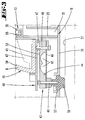
- the electric motor 9 is supported in a receiving part 13.
- This receiving part 13 is preferably not fixed in the fully assembled position of the food processor 1 by separate measures on the inwardly facing bottom 20 of the housing pan 18.
- the receiving part 13 is with respect to a plan according to Fig. 6
- the opening 21 is in this case formed with respect to the floor plan surface so that the electric motor 9 is preferably included without play with its stator 14.
- the receiving part 13 is covered by a lid-like housing portion 22, this essentially a horizontally oriented in operating position, the stator 14 covering blanket forming.
- the ceiling of the housing section 22 is penetrated by a projecting from the stator 14 in the operating position vertically above free end of the Rotorachs stressess 12, wherein further this free end is externally profiled outer wall for positive engagement of a corresponding coupling portion of the vessel side agitator 8.
- a central component 23 In the receiving part 13 inside a central component 23 is retracted. This extends with reference to a floor plan according to Fig. 6 essentially over the entire free inner extent of the receiving part 13 in the region of the opening 21, correspondingly forms a separation of the receiving part 13 in total in a vertically upper and a lower vertical area.
- a floor 20 vertically spaced, more preferably parallel to this extending bottom 24 of the component 23 which is adapted to the circumferential contour of the associated bridge 15 of the electric motor 9 opening 21 is provided.
- This is interspersed by the associated, vertically lower bridge 15, wherein the electric motor 9 is supported on the upper side 24 with the interposition of a circumferential seal 25 by means of the stator 14.
- the electric motor 9 is mounted in total in the receiving part 13, preferably by means of in FIG. 5 shown screws, the portions of the stator 14 axially parallel passing through with appropriately positioned screw receptacles of the receiving part 13 cooperate.
- the arrangement is further selected so that the vertical lower bridge 15 extends vertically above the device housing floor 20, which vertical distance preferably corresponds to about half the vertical distance between the device housing bottom 20 and bottom 24 of the receiving part 13.
- the vertically upwardly facing ceiling of the opposite bridge 16 is vertically spaced from the ceiling of the upper housing portion 22 wherein preferably here a vertical distance is selected, which corresponds to the vertical distance between the lower bridge 15 and the device housing bottom 20 substantially.
- the base 24 of the central component 23 merges into a vertically annular wall 26 surrounding the stator 14, preferably extending over the entire vertical height of the stator 14 starting from the base 24.
- the central component 23 preferably extends and substantially with respect to the rotor axis radially outward, in particular aligned parallel to the bottom 24, wherein the partition wall 27 thus formed approximately completely circumferentially attached to the vertical outer wall 28 of the receiving part 13, more preferably formed.
- the ceiling of the upper housing section 22, and more preferably the Genosuseau touchwandung 28 are inside wall, i. the electric motor 9 and the flow channels described in more detail below with a sound absorber material 29.
- This is preferably an open-cell foam, which is further preferably attached to the wall sections, for example glued.
- a vertically directed flow baffle 30 is more preferably formed. This is formed by a preferably perpendicular to the bottom 20 and thus in the operating position vertically oriented wall, which is further preferably integrally formed and the same material with the bottom 20.
- This flow baffle 30 completely encloses the vertical wall 26 of the central component 23, leaving a radial distance with respect to the rotor axis.
- the vertical height of the flow baffle 30 is in this case selected so that a radially upwardly facing edge edge of the same approximately at the level of half the vertical extent of the stator 14 extends. Accordingly, in addition to the radial spacing to the wall 28, a vertical distance between the pointing to vertical top free edge of the flow baffle 30 and the underside of the partition wall 27 a.
- the vertically superimposed areas open by the central component 23 in an anteroom preferably over the diameter of the annular portion of the receiving part 13.
- the lower region of the receiving part 13 formed by the central component 23 here forms an inflow channel 31 with a width considered transversely to the rotor axis which substantially corresponds to the internal transverse extension or diameter dimension of the outer wall 28, more preferably approximately 1.1 to 1, 5 times the largest transverse dimension of the stator 14.
- the inflow channel 31 extends from an inflow opening 32 provided at the rear in the wall of the chassis 19 to form a radial air path at least in axial overlap with the stator 16.
- a ski-like elevation 33 is shaped out of the bottom 20 in the region of the bottom 20.
- the partition wall 27 of the central component 23 is directed in this antechamber region to form the inflow channel 31 directed substantially downwards in the direction of the bottom 20, in this case preferably an acute angle of 5 to 15 degrees to the vertical enclosing, wherein the partition wall 27 further in Area of the downwardly facing end of the bend forms a preferably parallel to the bottom 20 extending bottom portion 34.
- This bottom portion 34 is in the further course towards the back of the case again in a sloping vertically upward, above the inflow opening 32 against the facing wall of the chassis 19 subsequent section.
- annular flow passage 35 left correspondingly also to the anteroom out in the section of the inflow channel formed there 31 opens.
- outflow channel 36 which is essentially the same and correspondingly extends above the inflow channel 31, further preferably horizontally and substantially vertically overlapping it Flow channel 35.
- a flow baffle 37 is also preferably provided here.
- This is preferably formed by a mounted on the receiving part 13, substantially vertically and thus in a plane parallel to the rotor axis extending board 38.
- This board 38 preferably carries electronic components, in particular for controlling and regulating the electric motor 9.
- the flow baffle 37 by a preferred formed in the vertical direction extending wall portion of the housing portion 22.
- the thus formed flow baffle 37 extends correspondingly preferably from the ceiling of the housing portion 22 vertically down to the formed by the S-shaped configuration of the partition wall 27 bead area, leaving a flow path.
- the flow baffle 37 in the outflow channel 36 is correspondingly preferably offset radially to the flow baffle 30 in the inflow channel 31, this more preferably in the direction of the rear of the device.
- the partition wall 27 between the inflow channel 31 and the outflow channel 36 correspondingly forms the ceiling of the inflow channel 31 and at the same time the bottom of the outflow channel 36.
- Associated with the partition 27 is formed radially outwardly of the wall 26 between this and the outer wall 28 has an upwardly open groove 39.
- a radially outwardly extending arm 40 is integrally formed on the outer wall 28.
- Two further arms 40 are formed substantially on both sides of the flow baffle 30.
- the boom 40 of the same material and integrally formed on the receiving part 13.
- the three arms 40 are further preferably arranged so that they in a plan according to Fig. 6 essentially raise a triangle.
- Each boom 40 has a preferably approximately half the vertical height of the outer wall 28 extending footprint 41. This preferably extends in parallel alignment with the bottom 24 of the receiving part 13.
- Each footprint 41 is further preferably adjacent to the outer wall 28 additionally bounded by walls 42 circumferentially.
- a weighing module 43 is attached at each boom 40.
- This weighing module 43 initially has a balance beam 44, which is designed as a so-called half-beam.
- the balance beam 44 is elongated, rod-shaped with a preferably approximately square cross-section.
- this is provided between two attachment areas with two notches 45.
- These notches 45 are each projected in a vertical plane of the balance beam 44, designed semicircular, wherein further the thus achieved, vault-shaped notches 45 preferably merge into one another such that the thus created semi-disc-shaped notched surfaces partially overlap.
- the balance beam 44 is further preferably provided with a lower plate portion 46. This is preferably a rigid plate part, preferably a metal sheet metal part. On the upper side, a strain gauge 53 is arranged on the balance beam 44.
- a spacer 47 is provided on the upper side of the balance beam 44.
- the associated mounting area is penetrated by a vertical bore through which a screw 48 for fixing the balance beam 44 to the, the footprint 41 forming portion of the receiving part side arm 40 occurs.
- the opposite, cantilevered region of the balance beam 44 is provided with a vertical bore. This is used to throughput of another screw 49 for fixing a device base 50.
- the device base 50 extends from the balance beam 44, starting from down vertically.
- each geometric connecting line a between two feet 50, in particular between vertical body axes of the feet 50, which connecting line a is a tilt axis, to a device center point S has the same distance , As a result, a tilt-safe installation of the food processor 1 on a work surface 51 is possible.
- the device center of gravity S is not necessarily on the vertical axis x, but may be offset to this particular radially.
- the device feet 50 pass through apertures 52 in the bottom 20 of the housing trough 18, which apertures 52 have at least one adapted to the largest diameter of a device base 50 opening cross section, so that the device 50 feet in particular in the vertical direction freely permeate the housing trough 18.
- the housing pan 18 is at a distance from the working surface 51 or at a distance from that through the shelves of the device feet 50 given installation level of the food processor 1 attached to the chassis 19 and at the above the housing tray 18 extending housing portion, so for example clipped or screwed with this.
- the chassis 19 forms, inter alia, preferably also the mixing vessel receptacle 6.
- the entire chassis 19, together with the housing trough 18, is supported on the bearing surfaces 41 of the receiving part-side arms 40 by shaped, load-bearing elements 54, the receiving part 13 in turn receiving support on a working surface 51 or the like via the weighing modules 43 and the device feet 50 connected thereto ,
- the weight of the chassis 19 and the housing pan 18 is detected via the weighing modules 43, moreover, as preferred, during operation of the food processor 1, also the weight of the mixing vessel 7, the content received in the mixing vessel 7 and further, in particular with the mixing vessel 7
- the mixing vessel 7 For example, to be connected components, such as the lid 11 or the agitator. 8
- the weight values recorded via the weighing modules 43 are displayed in the display 5, preferably taking the intrinsic weight of the components acting on the weighing modules 43 into account.
- the device power flow preferably moves from the device feet 50 via the associated weighing modules 43 directly through the load-bearing elements 54 of the chassis 19.
- the receiving part 13 remains out of the power flow and accordingly does not need to meet any special strength requirements.
- the weighing modules 43 and the device feet 50 connected thereto are already in a preferred embodiment for mounting the food processor 1 on the Receiving part 13 set.
- the electrical connections of the wiring 55 of all weighing modules 43 are combined in a collective plug 56.
- the collective plug 56 is further preferably attached to the receiving part 13, so for example. In the region of the groove 39
- the so preferably designed receiving part 13 accordingly constitutes a weighing collection module, which further preferably at the same time serves to hold the motor 9 and / or an air duct for cooling the motor 9 is formed.
- the housing pan 18 is initially deposited, for example, on a work surface 51.
- the further assembly of the individual device components is preferably carried out basically from above, i. towards the tub interior.
- the prepared receiving part 13 is preferably first inserted into the housing trough 18, while the receptacle-side device feet 50 penetrate through the openings 52 of the housing trough 18, which device feet 50 are supported on the same working surface 51 as the housing trough 18.
- the housing trough 18 preferably raised with parallel spacing of the bottom 20 of the housing trough 18 to the working surface 51, which lift the correspondingly formed apertures 52 allow. In the raised position, the housing pan 18 is connected to the chassis 19.
- Disassembly of the food processor 1 is preferably carried out in the reverse order, more preferably starting with a detachment of the housing trough 18 from the chassis 19 and lowering the housing trough 18 on the work surface 51st
- any necessary mounting openings in the housing trough 18 are closed by the receiving part 13, in particular by sections of the receiving part 13.
Landscapes
- Engineering & Computer Science (AREA)
- Food Science & Technology (AREA)
- Mechanical Engineering (AREA)
- Food-Manufacturing Devices (AREA)
- Mixers Of The Rotary Stirring Type (AREA)
Claims (9)
- Robot de cuisine (1) ayant une cuve de mélange (7) et un élément mélangeur (8) dans la cuve de mélange (7) et ayant en outre un moteur électrique (9) pour entrainer l'élément mélangeur (8), un boîtier support formant châssis (19) et un carter (18) formant le fond (20), dans lequel sont prévus en outre des pieds d'appareil (50) qui sont reliés à des modules de pesage (43), caractérisé en ce que les modules de pesage (43) sont liés à une pièce de réception commune (13) qui reçoit le câblage (55) nécessaire aux modules de pesage (43), dans lequel le carter (18), même avec les pieds d'appareil (50) montés, est apte à être monté sur le châssis (19) et/ou démonté du châssis (19).
- Robot de cuisine selon la revendication 1, caractérisé en ce que les modules de pesage (43) sont liés à une pièce de réception commune (13) et que la pièce de réception (13) est conçue également pour supporter le moteur (9) et/ou forme un conduit d'aération pour le refroidissement du moteur.
- Robot de cuisine selon l'une des revendications précédentes, caractérisé en ce que la pièce de réception (13) forme une rainure (39) ouverte vers le haut dans laquelle est reçu le câblage (55).
- Robot de cuisine selon l'une des revendications précédentes, caractérisé en ce que la pièce de réception (13) est réalisée sous une forme sensiblement d'anneau circulaire.
- Robot de cuisine selon l'une des revendications précédentes, caractérisé en ce que sont prévus trois pieds d'appareil avec trois modules de pesage (43) associés.
- Robot de cuisine selon l'une des revendications précédentes, caractérisé en ce qu'une ligne de liaison géométrique (a) de deux pieds d'appareil (50) définit un axe de basculement possible et que chaque axe de basculement présente une même distance à un centre de gravité (S) de l'appareil.
- Robot de cuisine selon l'une des revendications précédentes, caractérisé en ce que les modules de pesage (43) sont réalisés sous forme de poutres de pesage.
- Robot de cuisine selon l'une des revendications précédentes, caractérisé en ce que la pièce de réception (13) présente un connecteur lequel réunit l'ensemble des connexions électriques des modules de pesage (43).
- Procédé de montage d'un robot de cuisine (1) ayant une cuve de mélange (7) et un élément mélangeur (8) dans la cuve de mélange (7) et ayant en outre un moteur électrique (9) pour entrainer l'élément mélangeur (8), un boîtier support formant châssis (19) et un carter (18) formant le fond (20), dans lequel sont prévus en outre des pieds d'appareil (50) qui sont reliés à des modules de pesage (43), caractérisé en ce que d'abord est prévu le carter (18), que les pieds d'appareil (50), les modules de pesage (43) et la pièce de réception (13) recevant le câblage (55) sont montés dans le carter (18) par le haut et qu'ensuite le moteur (9) et le châssis (19) y sont logé et monté respectivement.
Applications Claiming Priority (1)
| Application Number | Priority Date | Filing Date | Title |
|---|---|---|---|
| DE102012104495A DE102012104495A1 (de) | 2012-05-24 | 2012-05-24 | Küchenmaschine mit einem Rührgefäß sowie Verfahren zur Montage einer Küchenmaschine |
Publications (2)
| Publication Number | Publication Date |
|---|---|
| EP2666397A1 EP2666397A1 (fr) | 2013-11-27 |
| EP2666397B1 true EP2666397B1 (fr) | 2016-06-22 |
Family
ID=48366213
Family Applications (1)
| Application Number | Title | Priority Date | Filing Date |
|---|---|---|---|
| EP13167279.2A Active EP2666397B1 (fr) | 2012-05-24 | 2013-05-10 | Machine de cuisine dotée d'un récipient de mélange et procédé de montage d'une machine de cuisine |
Country Status (6)
| Country | Link |
|---|---|
| EP (1) | EP2666397B1 (fr) |
| CN (1) | CN103417138B (fr) |
| DE (1) | DE102012104495A1 (fr) |
| ES (1) | ES2586834T3 (fr) |
| PL (1) | PL2666397T3 (fr) |
| PT (1) | PT2666397T (fr) |
Families Citing this family (3)
| Publication number | Priority date | Publication date | Assignee | Title |
|---|---|---|---|---|
| US10317274B2 (en) * | 2015-11-18 | 2019-06-11 | Whirlpool Corporation | Coffee grinder with integrated scale |
| CN107836980A (zh) * | 2016-09-20 | 2018-03-27 | 深圳市联创三金电器有限公司 | 多功能食物处理装置 |
| DE102017123690A1 (de) * | 2017-10-11 | 2019-04-11 | Vorwerk & Co. Interholding Gmbh | Elektromotorisch betriebene Küchenmaschine sowie Rührgefäß und Rührwerk dafür |
Family Cites Families (10)
| Publication number | Priority date | Publication date | Assignee | Title |
|---|---|---|---|---|
| DE4208368A1 (de) * | 1992-03-16 | 1993-09-23 | Braun Ag | Kraftmesseinrichtung fuer haushaltsgeraete |
| DE10219442B4 (de) | 2002-05-02 | 2010-09-16 | Mann + Hummel Gmbh | Steckverbindung |
| DE10337915A1 (de) | 2003-08-18 | 2005-04-14 | Vorwerk & Co. Interholding Gmbh | Reluktanzmotor |
| DE102008027353A1 (de) * | 2008-06-07 | 2009-12-10 | Vorwerk & Co. Interholding Gmbh | Küchenmaschine mit einem Rührgefäß |
| DE102008040740B4 (de) * | 2008-07-25 | 2018-12-27 | BSH Hausgeräte GmbH | Küchenmaschine mit einer Wägeeinrichtung und Verfahren zum Bestimmen eines Gewichts bei einer Küchenmaschine |
| DE102008040741A1 (de) * | 2008-07-25 | 2010-01-28 | BSH Bosch und Siemens Hausgeräte GmbH | Küchenmaschine mit einem mit mehreren Füßen ausgebildetem Basisteil |
| DE102010060650A1 (de) * | 2009-11-25 | 2011-05-26 | Vorwerk & Co. Interholding Gmbh | Küchenmaschine |
| DE102009058258A1 (de) * | 2009-12-10 | 2011-06-16 | Vorwerk & Co. Interholding Gmbh | Küchenmaschine |
| DE102009059242A1 (de) | 2009-12-21 | 2011-06-22 | Vorwerk & Co. Interholding GmbH, 42275 | Wägezelle für eine elektrische Waage |
| DE102009059294A1 (de) | 2009-12-23 | 2011-06-30 | ACO Severin Ahlmann GmbH & Co. KG, 24768 | Vorrichtung und Verfahren zur Isolation einer Bauteilwand und isolierter Wandaufbau |
-
2012
- 2012-05-24 DE DE102012104495A patent/DE102012104495A1/de not_active Withdrawn
-
2013
- 2013-05-10 PT PT131672792T patent/PT2666397T/pt unknown
- 2013-05-10 EP EP13167279.2A patent/EP2666397B1/fr active Active
- 2013-05-10 PL PL13167279.2T patent/PL2666397T3/pl unknown
- 2013-05-10 ES ES13167279.2T patent/ES2586834T3/es active Active
- 2013-05-24 CN CN201310323030.1A patent/CN103417138B/zh active Active
Also Published As
| Publication number | Publication date |
|---|---|
| EP2666397A1 (fr) | 2013-11-27 |
| DE102012104495A1 (de) | 2013-11-28 |
| CN103417138A (zh) | 2013-12-04 |
| ES2586834T3 (es) | 2016-10-19 |
| PL2666397T3 (pl) | 2016-10-31 |
| PT2666397T (pt) | 2016-08-26 |
| CN103417138B (zh) | 2017-07-21 |
Similar Documents
| Publication | Publication Date | Title |
|---|---|---|
| DE10325303A1 (de) | Modulares Küchensystem | |
| EP2666397B1 (fr) | Machine de cuisine dotée d'un récipient de mélange et procédé de montage d'une machine de cuisine | |
| DE102004056708B4 (de) | Sitzantriebsmotor und Sitzantriebssystem | |
| DE202010017848U1 (de) | Behälter mit höhenverstellbarem Boden | |
| DE69607399T2 (de) | Küchenhaube mit Abzug- und/oder Filteranlage | |
| DE102008055017B4 (de) | Geschirrspülmaschine | |
| EP3092936A1 (fr) | Lave-vaisselle | |
| DE102013106565A1 (de) | Einbauteil, beispielsweise einer Küchenmaschine sowie Küchenmaschine mit einem Rührgefäß | |
| CH677029A5 (fr) | ||
| EP2754824A2 (fr) | Porte à tambour dotée d'une unité d'entraînement disposée au niveau d'un élément de plafond en verre | |
| DE102012213001B4 (de) | Geschirrspülmaschine, insbesondere Haushaltsgeschirrspülmaschine | |
| DE102022207879B3 (de) | Kochfeldeinrichtung mit Wiegefunktion | |
| DE60006732T2 (de) | Rotierendes Messer | |
| EP3228218B1 (fr) | Élement de meuble | |
| DE102009031990A1 (de) | Gerät, insbesondere Küchenmaschine | |
| EP3943817A1 (fr) | Fourneau | |
| DE202008011881U1 (de) | Brotbackmaschine mit verstecktem Heizelement | |
| EP2395875B1 (fr) | Dispositif de support d'écran | |
| DE202019104969U1 (de) | Gargerät | |
| DE102012101757A1 (de) | In einem Haushaltsgerät eingebauter Elektromotor | |
| DE202008002877U1 (de) | Gehäuse für Elektrokochfelder | |
| DE69211112T2 (de) | Knetmaschine für Nahrungsprodukte | |
| EP3481513B1 (fr) | Corps d'appareil à utilisation flexible conçu pour un appareil de musculation | |
| EP4103015A1 (fr) | Dispositif de suspension et support principal | |
| DE102012109334A1 (de) | Hubsystem für ein höhenverstellbares Arbeitsplatzsystem und Arbeitsplatzsystem mit einem solchen Hubsystem |
Legal Events
| Date | Code | Title | Description |
|---|---|---|---|
| PUAI | Public reference made under article 153(3) epc to a published international application that has entered the european phase |
Free format text: ORIGINAL CODE: 0009012 |
|
| AK | Designated contracting states |
Kind code of ref document: A1 Designated state(s): AL AT BE BG CH CY CZ DE DK EE ES FI FR GB GR HR HU IE IS IT LI LT LU LV MC MK MT NL NO PL PT RO RS SE SI SK SM TR |
|
| AX | Request for extension of the european patent |
Extension state: BA ME |
|
| 17P | Request for examination filed |
Effective date: 20140509 |
|
| RBV | Designated contracting states (corrected) |
Designated state(s): AL AT BE BG CH CY CZ DE DK EE ES FI FR GB GR HR HU IE IS IT LI LT LU LV MC MK MT NL NO PL PT RO RS SE SI SK SM TR |
|
| RIC1 | Information provided on ipc code assigned before grant |
Ipc: A47J 43/04 20060101AFI20141105BHEP Ipc: A47J 43/07 20060101ALI20141105BHEP Ipc: A47J 43/046 20060101ALI20141105BHEP |
|
| 17Q | First examination report despatched |
Effective date: 20141117 |
|
| GRAP | Despatch of communication of intention to grant a patent |
Free format text: ORIGINAL CODE: EPIDOSNIGR1 |
|
| INTG | Intention to grant announced |
Effective date: 20160127 |
|
| GRAS | Grant fee paid |
Free format text: ORIGINAL CODE: EPIDOSNIGR3 |
|
| GRAA | (expected) grant |
Free format text: ORIGINAL CODE: 0009210 |
|
| AK | Designated contracting states |
Kind code of ref document: B1 Designated state(s): AL AT BE BG CH CY CZ DE DK EE ES FI FR GB GR HR HU IE IS IT LI LT LU LV MC MK MT NL NO PL PT RO RS SE SI SK SM TR |
|
| REG | Reference to a national code |
Ref country code: GB Ref legal event code: FG4D Free format text: NOT ENGLISH |
|
| REG | Reference to a national code |
Ref country code: CH Ref legal event code: EP |
|
| REG | Reference to a national code |
Ref country code: IE Ref legal event code: FG4D Free format text: LANGUAGE OF EP DOCUMENT: GERMAN |
|
| REG | Reference to a national code |
Ref country code: AT Ref legal event code: REF Ref document number: 807152 Country of ref document: AT Kind code of ref document: T Effective date: 20160715 |
|
| REG | Reference to a national code |
Ref country code: DE Ref legal event code: R096 Ref document number: 502013003442 Country of ref document: DE |
|
| REG | Reference to a national code |
Ref country code: PT Ref legal event code: SC4A Ref document number: 2666397 Country of ref document: PT Date of ref document: 20160826 Kind code of ref document: T Free format text: AVAILABILITY OF NATIONAL TRANSLATION Effective date: 20160819 |
|
| REG | Reference to a national code |
Ref country code: ES Ref legal event code: FG2A Ref document number: 2586834 Country of ref document: ES Kind code of ref document: T3 Effective date: 20161019 |
|
| REG | Reference to a national code |
Ref country code: LT Ref legal event code: MG4D |
|
| REG | Reference to a national code |
Ref country code: NL Ref legal event code: MP Effective date: 20160622 |
|
| PG25 | Lapsed in a contracting state [announced via postgrant information from national office to epo] |
Ref country code: FI Free format text: LAPSE BECAUSE OF FAILURE TO SUBMIT A TRANSLATION OF THE DESCRIPTION OR TO PAY THE FEE WITHIN THE PRESCRIBED TIME-LIMIT Effective date: 20160622 Ref country code: LT Free format text: LAPSE BECAUSE OF FAILURE TO SUBMIT A TRANSLATION OF THE DESCRIPTION OR TO PAY THE FEE WITHIN THE PRESCRIBED TIME-LIMIT Effective date: 20160622 Ref country code: NO Free format text: LAPSE BECAUSE OF FAILURE TO SUBMIT A TRANSLATION OF THE DESCRIPTION OR TO PAY THE FEE WITHIN THE PRESCRIBED TIME-LIMIT Effective date: 20160922 |
|
| PG25 | Lapsed in a contracting state [announced via postgrant information from national office to epo] |
Ref country code: SE Free format text: LAPSE BECAUSE OF FAILURE TO SUBMIT A TRANSLATION OF THE DESCRIPTION OR TO PAY THE FEE WITHIN THE PRESCRIBED TIME-LIMIT Effective date: 20160622 Ref country code: HR Free format text: LAPSE BECAUSE OF FAILURE TO SUBMIT A TRANSLATION OF THE DESCRIPTION OR TO PAY THE FEE WITHIN THE PRESCRIBED TIME-LIMIT Effective date: 20160622 Ref country code: RS Free format text: LAPSE BECAUSE OF FAILURE TO SUBMIT A TRANSLATION OF THE DESCRIPTION OR TO PAY THE FEE WITHIN THE PRESCRIBED TIME-LIMIT Effective date: 20160622 Ref country code: GR Free format text: LAPSE BECAUSE OF FAILURE TO SUBMIT A TRANSLATION OF THE DESCRIPTION OR TO PAY THE FEE WITHIN THE PRESCRIBED TIME-LIMIT Effective date: 20160923 Ref country code: NL Free format text: LAPSE BECAUSE OF FAILURE TO SUBMIT A TRANSLATION OF THE DESCRIPTION OR TO PAY THE FEE WITHIN THE PRESCRIBED TIME-LIMIT Effective date: 20160622 Ref country code: LV Free format text: LAPSE BECAUSE OF FAILURE TO SUBMIT A TRANSLATION OF THE DESCRIPTION OR TO PAY THE FEE WITHIN THE PRESCRIBED TIME-LIMIT Effective date: 20160622 |
|
| PG25 | Lapsed in a contracting state [announced via postgrant information from national office to epo] |
Ref country code: SK Free format text: LAPSE BECAUSE OF FAILURE TO SUBMIT A TRANSLATION OF THE DESCRIPTION OR TO PAY THE FEE WITHIN THE PRESCRIBED TIME-LIMIT Effective date: 20160622 Ref country code: EE Free format text: LAPSE BECAUSE OF FAILURE TO SUBMIT A TRANSLATION OF THE DESCRIPTION OR TO PAY THE FEE WITHIN THE PRESCRIBED TIME-LIMIT Effective date: 20160622 Ref country code: CZ Free format text: LAPSE BECAUSE OF FAILURE TO SUBMIT A TRANSLATION OF THE DESCRIPTION OR TO PAY THE FEE WITHIN THE PRESCRIBED TIME-LIMIT Effective date: 20160622 Ref country code: RO Free format text: LAPSE BECAUSE OF FAILURE TO SUBMIT A TRANSLATION OF THE DESCRIPTION OR TO PAY THE FEE WITHIN THE PRESCRIBED TIME-LIMIT Effective date: 20160622 Ref country code: IS Free format text: LAPSE BECAUSE OF FAILURE TO SUBMIT A TRANSLATION OF THE DESCRIPTION OR TO PAY THE FEE WITHIN THE PRESCRIBED TIME-LIMIT Effective date: 20161022 |
|
| PG25 | Lapsed in a contracting state [announced via postgrant information from national office to epo] |
Ref country code: SM Free format text: LAPSE BECAUSE OF FAILURE TO SUBMIT A TRANSLATION OF THE DESCRIPTION OR TO PAY THE FEE WITHIN THE PRESCRIBED TIME-LIMIT Effective date: 20160622 |
|
| REG | Reference to a national code |
Ref country code: DE Ref legal event code: R097 Ref document number: 502013003442 Country of ref document: DE |
|
| PLBE | No opposition filed within time limit |
Free format text: ORIGINAL CODE: 0009261 |
|
| STAA | Information on the status of an ep patent application or granted ep patent |
Free format text: STATUS: NO OPPOSITION FILED WITHIN TIME LIMIT |
|
| REG | Reference to a national code |
Ref country code: FR Ref legal event code: PLFP Year of fee payment: 5 |
|
| 26N | No opposition filed |
Effective date: 20170323 |
|
| PG25 | Lapsed in a contracting state [announced via postgrant information from national office to epo] |
Ref country code: DK Free format text: LAPSE BECAUSE OF FAILURE TO SUBMIT A TRANSLATION OF THE DESCRIPTION OR TO PAY THE FEE WITHIN THE PRESCRIBED TIME-LIMIT Effective date: 20160622 |
|
| PG25 | Lapsed in a contracting state [announced via postgrant information from national office to epo] |
Ref country code: SI Free format text: LAPSE BECAUSE OF FAILURE TO SUBMIT A TRANSLATION OF THE DESCRIPTION OR TO PAY THE FEE WITHIN THE PRESCRIBED TIME-LIMIT Effective date: 20160622 Ref country code: LU Free format text: LAPSE BECAUSE OF NON-PAYMENT OF DUE FEES Effective date: 20170531 |
|
| REG | Reference to a national code |
Ref country code: CH Ref legal event code: PL |
|
| PG25 | Lapsed in a contracting state [announced via postgrant information from national office to epo] |
Ref country code: MC Free format text: LAPSE BECAUSE OF FAILURE TO SUBMIT A TRANSLATION OF THE DESCRIPTION OR TO PAY THE FEE WITHIN THE PRESCRIBED TIME-LIMIT Effective date: 20160622 |
|
| REG | Reference to a national code |
Ref country code: IE Ref legal event code: MM4A |
|
| PG25 | Lapsed in a contracting state [announced via postgrant information from national office to epo] |
Ref country code: LI Free format text: LAPSE BECAUSE OF NON-PAYMENT OF DUE FEES Effective date: 20170531 Ref country code: CH Free format text: LAPSE BECAUSE OF NON-PAYMENT OF DUE FEES Effective date: 20170531 |
|
| PG25 | Lapsed in a contracting state [announced via postgrant information from national office to epo] |
Ref country code: LU Free format text: LAPSE BECAUSE OF NON-PAYMENT OF DUE FEES Effective date: 20170510 |
|
| REG | Reference to a national code |
Ref country code: BE Ref legal event code: MM Effective date: 20170531 |
|
| PG25 | Lapsed in a contracting state [announced via postgrant information from national office to epo] |
Ref country code: IE Free format text: LAPSE BECAUSE OF NON-PAYMENT OF DUE FEES Effective date: 20170510 |
|
| REG | Reference to a national code |
Ref country code: FR Ref legal event code: PLFP Year of fee payment: 6 |
|
| PG25 | Lapsed in a contracting state [announced via postgrant information from national office to epo] |
Ref country code: BE Free format text: LAPSE BECAUSE OF NON-PAYMENT OF DUE FEES Effective date: 20170531 |
|
| PG25 | Lapsed in a contracting state [announced via postgrant information from national office to epo] |
Ref country code: MT Free format text: LAPSE BECAUSE OF FAILURE TO SUBMIT A TRANSLATION OF THE DESCRIPTION OR TO PAY THE FEE WITHIN THE PRESCRIBED TIME-LIMIT Effective date: 20160622 |
|
| PG25 | Lapsed in a contracting state [announced via postgrant information from national office to epo] |
Ref country code: AL Free format text: LAPSE BECAUSE OF FAILURE TO SUBMIT A TRANSLATION OF THE DESCRIPTION OR TO PAY THE FEE WITHIN THE PRESCRIBED TIME-LIMIT Effective date: 20160622 |
|
| PG25 | Lapsed in a contracting state [announced via postgrant information from national office to epo] |
Ref country code: HU Free format text: LAPSE BECAUSE OF FAILURE TO SUBMIT A TRANSLATION OF THE DESCRIPTION OR TO PAY THE FEE WITHIN THE PRESCRIBED TIME-LIMIT; INVALID AB INITIO Effective date: 20130510 |
|
| REG | Reference to a national code |
Ref country code: AT Ref legal event code: MM01 Ref document number: 807152 Country of ref document: AT Kind code of ref document: T Effective date: 20180510 |
|
| PG25 | Lapsed in a contracting state [announced via postgrant information from national office to epo] |
Ref country code: BG Free format text: LAPSE BECAUSE OF FAILURE TO SUBMIT A TRANSLATION OF THE DESCRIPTION OR TO PAY THE FEE WITHIN THE PRESCRIBED TIME-LIMIT Effective date: 20160622 |
|
| PG25 | Lapsed in a contracting state [announced via postgrant information from national office to epo] |
Ref country code: CY Free format text: LAPSE BECAUSE OF NON-PAYMENT OF DUE FEES Effective date: 20160622 Ref country code: AT Free format text: LAPSE BECAUSE OF NON-PAYMENT OF DUE FEES Effective date: 20180510 |
|
| PG25 | Lapsed in a contracting state [announced via postgrant information from national office to epo] |
Ref country code: MK Free format text: LAPSE BECAUSE OF FAILURE TO SUBMIT A TRANSLATION OF THE DESCRIPTION OR TO PAY THE FEE WITHIN THE PRESCRIBED TIME-LIMIT Effective date: 20160622 |
|
| PGFP | Annual fee paid to national office [announced via postgrant information from national office to epo] |
Ref country code: TR Payment date: 20200508 Year of fee payment: 8 |
|
| P01 | Opt-out of the competence of the unified patent court (upc) registered |
Effective date: 20230517 |
|
| PGFP | Annual fee paid to national office [announced via postgrant information from national office to epo] |
Ref country code: DE Payment date: 20250519 Year of fee payment: 13 Ref country code: PL Payment date: 20250425 Year of fee payment: 13 |
|
| PGFP | Annual fee paid to national office [announced via postgrant information from national office to epo] |
Ref country code: GB Payment date: 20250522 Year of fee payment: 13 Ref country code: ES Payment date: 20250616 Year of fee payment: 13 |
|
| PGFP | Annual fee paid to national office [announced via postgrant information from national office to epo] |
Ref country code: IT Payment date: 20250530 Year of fee payment: 13 |
|
| PGFP | Annual fee paid to national office [announced via postgrant information from national office to epo] |
Ref country code: PT Payment date: 20250507 Year of fee payment: 13 |
|
| PGFP | Annual fee paid to national office [announced via postgrant information from national office to epo] |
Ref country code: FR Payment date: 20250523 Year of fee payment: 13 |