EP2664779A1 - Soupape pour le dosage de fluide - Google Patents
Soupape pour le dosage de fluide Download PDFInfo
- Publication number
- EP2664779A1 EP2664779A1 EP13160890.3A EP13160890A EP2664779A1 EP 2664779 A1 EP2664779 A1 EP 2664779A1 EP 13160890 A EP13160890 A EP 13160890A EP 2664779 A1 EP2664779 A1 EP 2664779A1
- Authority
- EP
- European Patent Office
- Prior art keywords
- valve
- valve needle
- needle
- slot
- deformation
- Prior art date
- Legal status (The legal status is an assumption and is not a legal conclusion. Google has not performed a legal analysis and makes no representation as to the accuracy of the status listed.)
- Granted
Links
Images
Classifications
-
- F—MECHANICAL ENGINEERING; LIGHTING; HEATING; WEAPONS; BLASTING
- F02—COMBUSTION ENGINES; HOT-GAS OR COMBUSTION-PRODUCT ENGINE PLANTS
- F02M—SUPPLYING COMBUSTION ENGINES IN GENERAL WITH COMBUSTIBLE MIXTURES OR CONSTITUENTS THEREOF
- F02M51/00—Fuel-injection apparatus characterised by being operated electrically
- F02M51/06—Injectors peculiar thereto with means directly operating the valve needle
- F02M51/061—Injectors peculiar thereto with means directly operating the valve needle using electromagnetic operating means
- F02M51/0625—Injectors peculiar thereto with means directly operating the valve needle using electromagnetic operating means characterised by arrangement of mobile armatures
- F02M51/0664—Injectors peculiar thereto with means directly operating the valve needle using electromagnetic operating means characterised by arrangement of mobile armatures having a cylindrically or partly cylindrically shaped armature, e.g. entering the winding; having a plate-shaped or undulated armature entering the winding
- F02M51/0671—Injectors peculiar thereto with means directly operating the valve needle using electromagnetic operating means characterised by arrangement of mobile armatures having a cylindrically or partly cylindrically shaped armature, e.g. entering the winding; having a plate-shaped or undulated armature entering the winding the armature having an elongated valve body attached thereto
- F02M51/0682—Injectors peculiar thereto with means directly operating the valve needle using electromagnetic operating means characterised by arrangement of mobile armatures having a cylindrically or partly cylindrically shaped armature, e.g. entering the winding; having a plate-shaped or undulated armature entering the winding the armature having an elongated valve body attached thereto the body being hollow and its interior communicating with the fuel flow
-
- F—MECHANICAL ENGINEERING; LIGHTING; HEATING; WEAPONS; BLASTING
- F02—COMBUSTION ENGINES; HOT-GAS OR COMBUSTION-PRODUCT ENGINE PLANTS
- F02M—SUPPLYING COMBUSTION ENGINES IN GENERAL WITH COMBUSTIBLE MIXTURES OR CONSTITUENTS THEREOF
- F02M51/00—Fuel-injection apparatus characterised by being operated electrically
- F02M51/06—Injectors peculiar thereto with means directly operating the valve needle
- F02M51/061—Injectors peculiar thereto with means directly operating the valve needle using electromagnetic operating means
- F02M51/0625—Injectors peculiar thereto with means directly operating the valve needle using electromagnetic operating means characterised by arrangement of mobile armatures
- F02M51/0664—Injectors peculiar thereto with means directly operating the valve needle using electromagnetic operating means characterised by arrangement of mobile armatures having a cylindrically or partly cylindrically shaped armature, e.g. entering the winding; having a plate-shaped or undulated armature entering the winding
- F02M51/0685—Injectors peculiar thereto with means directly operating the valve needle using electromagnetic operating means characterised by arrangement of mobile armatures having a cylindrically or partly cylindrically shaped armature, e.g. entering the winding; having a plate-shaped or undulated armature entering the winding the armature and the valve being allowed to move relatively to each other or not being attached to each other
-
- F—MECHANICAL ENGINEERING; LIGHTING; HEATING; WEAPONS; BLASTING
- F02—COMBUSTION ENGINES; HOT-GAS OR COMBUSTION-PRODUCT ENGINE PLANTS
- F02M—SUPPLYING COMBUSTION ENGINES IN GENERAL WITH COMBUSTIBLE MIXTURES OR CONSTITUENTS THEREOF
- F02M61/00—Fuel-injectors not provided for in groups F02M39/00 - F02M57/00 or F02M67/00
- F02M61/04—Fuel-injectors not provided for in groups F02M39/00 - F02M57/00 or F02M67/00 having valves, e.g. having a plurality of valves in series
- F02M61/10—Other injectors with elongated valve bodies, i.e. of needle-valve type
-
- F—MECHANICAL ENGINEERING; LIGHTING; HEATING; WEAPONS; BLASTING
- F02—COMBUSTION ENGINES; HOT-GAS OR COMBUSTION-PRODUCT ENGINE PLANTS
- F02M—SUPPLYING COMBUSTION ENGINES IN GENERAL WITH COMBUSTIBLE MIXTURES OR CONSTITUENTS THEREOF
- F02M2200/00—Details of fuel-injection apparatus, not otherwise provided for
- F02M2200/26—Fuel-injection apparatus with elastically deformable elements other than coil springs
-
- F—MECHANICAL ENGINEERING; LIGHTING; HEATING; WEAPONS; BLASTING
- F02—COMBUSTION ENGINES; HOT-GAS OR COMBUSTION-PRODUCT ENGINE PLANTS
- F02M—SUPPLYING COMBUSTION ENGINES IN GENERAL WITH COMBUSTIBLE MIXTURES OR CONSTITUENTS THEREOF
- F02M2200/00—Details of fuel-injection apparatus, not otherwise provided for
- F02M2200/30—Fuel-injection apparatus having mechanical parts, the movement of which is damped
- F02M2200/306—Fuel-injection apparatus having mechanical parts, the movement of which is damped using mechanical means
Definitions
- the invention is based on a valve for metering fluid according to the preamble of claim 1, wherein the standing for a flowing or flowing medium superordinate term fluid is used in accordance with the fluid flow theory for gases and liquids.
- a magnet armature of a valve needle actuating electromagnet frictionally fixed on the valve needle is a magnet armature of a valve needle actuating electromagnet frictionally fixed on the valve needle.
- the valve needle has a closing body, which forms a sealing seat together with the valve seat at the valve opening.
- a return spring which is supported between the end of the valve needle facing away from the closing body and an adjusting sleeve, presses the closing body onto the valve seat.
- the valve needle has a collar-shaped anchor stop and a Mitauerflansch, between which the magnet armature is able to move axially on the valve needle.
- a Vorhubfeder presses the armature to the anchor stop.
- the armature When current is applied to the electromagnet, the armature is moved counter to the spring force of the pre-stroke and return spring in the stroke direction.
- the total stroke of the armature is divided into a forward stroke and an opening stroke.
- the closing body still remains on the valve seat.
- the opening stroke with lifting of the closing body from the valve seat starts as soon as the armature strikes the driving flange after the end of the forward stroke and carries along it the valve needle in the stroke direction.
- Such a valve has over a valve with rigid connection of armature and valve needle the advantage that the moving during valve actuated inertial mass is divided into two sub-masses, namely magnet armature and valve needle with closing body, resulting in a noise attenuation in valve opening and valve closing.
- Preller of the armature are largely attenuated by the Vorhubfeder. This Preller lead when valve closing after the first placement of the closing body on the valve seat to renewed lifting of the closing body from the valve seat and thus to an uncontrolled, short-term lifting of the sealing seat and opening the valve and thus to a non-reproducible Zumessmenge of fluid.
- Ankerkeweg are off DE 198 49 210 A1 .
- the metering valve according to the invention with the features of claim 1 has the advantage that the advantages of the valves with so-called.
- Ankerkaweg such as avoid bouncing and mechanical booster, preserved by the formation of the valve needle with different stiffness in the tension and compression direction, without the disadvantages associated with these known structural designs of these valves, such as a variety of components and joints, high manufacturing costs, dependency on manufacturing tolerances and fluid used by existing hydraulic crimp, exhibit.
- the number of components in the valve according to the invention is not greater than for valves with a rigid connection Actuator and valve needle, and accordingly simplifies the assembly process. Since less function-determining tolerances are to be observed, the production costs and the sample spread in the functional values, in particular in the quantitative metering of fluid, are reduced.
- the predetermined load from which elastic deformations of the valve needle occur chosen smaller than the sum of the minimum allowable restoring or closing force acting in the pressure direction on the valve needle return member and a minimum existing closing force of the fluid the valve needle is exerted with closing body.
- acting on the valve needle in the compression direction greater closing forces occurs elastic deformation of the valve needle one.
- the closing body Due to the increasing deformation with increasing stiffness of the valve needle, the closing body is pressed more strongly on the valve seat, so that a defined assignment of actuator and valve needle is ensured in the idle state of the closed valve, such as always a constant working air gap between the armature and magnetic core of the solenoid is present ,
- the valve needle in at least one needle section at least a pair of deformation webs which are diametrically opposed to each other and elastically on reaching the predetermined load or buckle.
- the deformation webs are advantageously obtained in manufacturing technology in that in the solid or hollow valve needle in at least one needle section at least one in the axial direction of the valve needle extending slot is introduced with a limited slot length.
- a hollow valve needle can be rolled out of a metal sheet with at least two preferably punched-out recesses of limited axial length, wherein two recesses each diametrically opposed in the hollow valve needle form a slot.
- the parallel to the longitudinal edges extending joints of the sheet are materially connected to each other, eg welded.
- a hollow valve needle of two bent sheets are assembled, each having at least one parallel to the longitudinal edges of the sheet extending, preferably punched recess of limited axial length and are integrally connected to the abutting longitudinal edges together so that in turn two in the hollow valve needle each diametrically opposed recesses form a slot.
- a directed buckling or buckling of the Veformungsstege is determined and supported according to an advantageous embodiment of the invention by joints, which are incorporated at the slot ends and in the slot center of at least one slot in the valve needle and preferably formed by cross-sectional constrictions in the deformation webs.
- cross-sectional constrictions are realized in accordance with an advantageous embodiment of the invention by a respective inserted into the valve needle transverse bore at each of the two slot ends and introduced into the valve needle, circumferential groove in slot center, so buckle the deformation webs when exceeding the predetermined load, the so-called.
- Buckling load inside and support each other. The mutual support increases the rigidity of the valve needle in the pressure direction.
- the buckling of the deformation webs inward can also be achieved in that the deformation webs are pre-bent by plastic deformation from its extended position by a few degrees inwards.
- cross-sectional constrictions are realized according to an advantageous embodiment of the invention by a respective inserted into the valve needle, circumferential groove at the slot ends and introduced into the valve needle transverse bore in slot center, so buckle the deformation webs when exceeding the buckling load to the outside.
- the rigidity of the valve needle increases in the printing direction.
- the buckling of the deformation webs to the outside can also be promoted according to an alternative embodiment of the invention in that the deformation webs are pre-bent by plastic deformation from the extended position by a few degrees outwards.
- valve for metering fluid is used for example as an injection valve for injecting fuel in a fuel injection system of internal combustion engines.
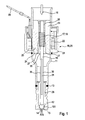
- the valve has a sleeve-shaped valve housing 11, in whose literallyess workedes end a valve body 12 and in its inlet end a not shown here Connecting piece for connecting a fluid line for the fluid inlet 10 is used fluid-tight.
- the valve body 12 is materially connected to the valve housing 11, wherein the material connection is symbolized by the weld 13.
- a metering or valve opening 14 is formed with a valve seat 15 surrounding the valve opening 14.
- valve needle 16 has at its valve opening 14 facing, literallyess districten needle end on a closing body 161 which forms a sealing seat with the valve seat 15.
- the closing body 161 is here formed like a ball and welded to the front end of the here massive valve needle 16. However, the closing body 161 can also be designed in one piece with the valve needle 16.
- the sealing seat 16 is produced or canceled by actuating the valve needle 16.
- the valve needle 16 is loaded to produce the sealing seat by a return member 18 to pressure and to cancel the sealing seat of an actuator 19 to train.
- the return member 18 is formed as a compression spring 17 and the actuator 19 as an electromagnet 20.
- other actuators 19 may be used, for. B. a piezoelectric or magnetostrictive actuator.
- the electromagnet 20 has in known manner a magnetic pot 21, a magnetic coil 22, a magnetic core 23 and a magnet armature 24.
- the magnet pot 21 is pushed onto the valve housing 11 and welded with its bottom of the pot on the valve housing 11 and takes the solenoid 22 axially immovable.
- the hollow cylindrical magnetic core 23 is positively inserted into the valve housing 11 and receives the compression spring 17 in the hollow core interior.
- the axially displaceably guided in the valve housing 11 Magentanker 24 is rigidly mounted on the valve needle 16, z. B. with this cohesively connected, resulting in FIG. 1 symbolized by the weld 35.
- the mutually facing annular end faces of armature 24 and magnetic core 23 include a working air gap 25 of the electromagnet 20 a.
- the compression spring 17 is supported on the one hand on the armature 24 and on the other hand on an adjustment sleeve 26 which is screwed into the magnetic core 23.
- flow channels 27 are held, which produce via the adjusting sleeve 26 a fluid connection from the inlet 10 to one of the valve opening 14 upstream, enclosed by the valve body 12 and the valve housing 11 valve chamber 28.
- the magnetic coil 22 is by means of an electric Connection plug 29 can be energized.
- the connecting piece for the fluid supply line and a connector housing 29 enclosing, not shown here plug housing are formed by a plastic casing which also at least partially surrounds the magnet pot 21 (not shown here).
- valve needle 16 two advantages are achieved in this valve, which also have valves with Vorhubfeder and Ankerkeweg, but in production and assembly are significantly more expensive.
- One advantage is the substantial elimination of the bumpers when closing the valve opening 14, ie during manufacture of the sealing seat, whereby the closing body remains after its first placement on the valve seat on this and ensures a reproducible metering of fluid by maintaining the sealing seat.
- the other advantage is the recovery of a so-called boost effect, d. H. a short-term acceleration of the armature 24 during valve opening, which leads to a reduction of the required magnetic force when lifting the sealing seat and allows a reduction in the power of the electromagnet 20.
- the valve needle 16 shown in the exemplary embodiments has different stiffnesses in the tensile and compressive directions in such a way that the valve needle 16 is almost invariably stiff when loaded in the direction of pull, but under load in the direction of pressure a stiffness permitting elastic deformations until a predetermined load is reached has and on the other hand assumes an increased stiffness after the occurrence of deformations.
- the predetermined load hereinafter referred to as buckling load, is preferably selected to be smaller than the sum of the minimum allowable restoring or closing force of the pressure acting on the valve needle 16 return member 18, so the pressure force of the compression spring 17, and the minimum existing closing force, the Fluid is exerted on the valve needle 16 with closing body 161.
- valve needle 16 in at least one needle section at least a pair of diametrically opposed deformation webs 30, which on reaching the predetermined load, so the buckling load, elastically on or buckle.
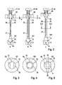
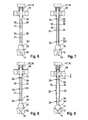
- FIG. 5 are in a needle portion of the valve needle 16 has two pairs of diametrically opposed each deformation webs 30.
- FIG. 6 is in two axially successive needle portions of the valve needle 16 each have a pair of mutually opposite deformation webs 30 available.
- At least one slot 31 extending in the axial direction of the valve needle 16 with a limited slot length is introduced into the massive valve needle 16.
- the valve needle 16 has only one slot 31.
- the massive valve needle 16 can also be a hollow valve needle 16 are used, which has one or more slots 31 in the same way.
- the hollow valve needle 16 can be used for the fluid flow from the inlet 10 to the valve chamber 28, so that separate flow channels 27 can be omitted in the armature 24.
- the slot 31 can be cut into the hollow cylindrical valve needle 16, milled or pierced, as in FIG. 4 is shown.
- the valve needle 16 can also be rolled out of a metal sheet having at least two elongated recesses of limited axial length.
- the recesses are arranged so that when rolled sheet each two recesses are diametrically opposed to each other and form a valve needle 16 crossing slot 31.
- the parallel to the longitudinal edges of the Austanzungen extending joints of the sheet are materially connected to each other, for. B. welded.
- the electromagnet 20 as an actuator 19 can advantageously be dispensed with the stoffschüssige connection of the sheet and instead the rolled sheet on mutually averted ends with the closing body 161 and the armature 24 of the electromagnet 20 materially connected, z. B. on or welded, be.
- the hollow valve needle 16 are assembled from two bent sheets, wherein in each sheet at least one elongated recess is incorporated, the longitudinal edges extending parallel to the longitudinal edges of the sheet.
- the two bent sheets are placed against each other and cohesively connected to the abutting longitudinal edges together, z. B. welded.
- the recesses are arranged in the sheets, that two in the finished valve needle 16 each diametrically opposed recesses form a valve needle 16 crossing slot 31.
- the production of the recesses can be made by punching, cutting or milling.
- FIG. 2 is the behavior of the valve needle 16 schematically outlined with their different stiffnesses in the tensile and compressive direction during valve closing and valve opening.
- valve In FIG. 1 and Figure 2C the valve is open, that is lifted by energizing the electromagnet 20 of the closing body 161 from the valve seat 15.
- the valve needle 16 is loaded in the pulling direction and assumes its normal stretched rod shape.
- FIG. 2A the valve is closed.
- the electromagnet 20 is not energized, and the compression spring 17 presses the closing body 161 on the valve seat 15.
- the valve needle 16 is loaded under pressure, whereby due to the lower rigidity of the valve needle 16 in the pressure direction and the exceeding of the buckling load, the two deformation webs 30 are buckled inwardly and touch each other in the middle. By this support of the two deformation webs 30 together, the stiffness of the valve needle 16 is increased again in the pressure direction after deformation of the deformation webs 30 and the valve reliably kept closed with the valve opening 14 closed.
- the buckling of the deformation webs 30 according to FIG. 2A can be further supported by the deformation webs 30 are pre-bent by plastic deformation from its extended position by a few degrees inwards.
- the deformation webs 30 may buckle outward under load in the direction of compression and exceeding the buckling load, wherein the centers of the deformation webs 30 move away from each other.
- a buckling may e.g. be achieved in that the deformation webs 30 are pre-bent by plastic deformation from the extended position by a few degrees outwards.
- valve needle 16 In the embodiment of the valve needle 16 according to FIGS. 8 and 9 is the cross-sectional constriction 32 realized at each of the two slot ends by an inserted into the valve needle 16, circumferential groove 34 and the cross-sectional constriction 32 in the slot center by an inserted into the valve needle 16 transverse bore 33.
- grooves 34 and transverse bore 33 In this arrangement of grooves 34 and transverse bore 33, the deformation webs 30 buckle outwardly, as in FIG. 9 is shown.
- the rigidity of the valve needle 16 Upon reaching the maximum Ausknickung, ie the maximum distance of the deformation webs 30 in web center from each other, the rigidity of the valve needle 16 increases in the printing direction.
Landscapes
- Engineering & Computer Science (AREA)
- Chemical & Material Sciences (AREA)
- Combustion & Propulsion (AREA)
- Mechanical Engineering (AREA)
- General Engineering & Computer Science (AREA)
- Physics & Mathematics (AREA)
- Electromagnetism (AREA)
- Magnetically Actuated Valves (AREA)
Applications Claiming Priority (1)
| Application Number | Priority Date | Filing Date | Title |
|---|---|---|---|
| DE102012208136A DE102012208136A1 (de) | 2012-05-15 | 2012-05-15 | Ventil zum Zumessen von Fluid |
Publications (2)
| Publication Number | Publication Date |
|---|---|
| EP2664779A1 true EP2664779A1 (fr) | 2013-11-20 |
| EP2664779B1 EP2664779B1 (fr) | 2016-01-20 |
Family
ID=48044597
Family Applications (1)
| Application Number | Title | Priority Date | Filing Date |
|---|---|---|---|
| EP13160890.3A Active EP2664779B1 (fr) | 2012-05-15 | 2013-03-25 | Soupape pour le dosage de fluide |
Country Status (2)
| Country | Link |
|---|---|
| EP (1) | EP2664779B1 (fr) |
| DE (1) | DE102012208136A1 (fr) |
Cited By (5)
| Publication number | Priority date | Publication date | Assignee | Title |
|---|---|---|---|---|
| WO2016096217A1 (fr) * | 2014-12-18 | 2016-06-23 | Robert Bosch Gmbh | Injecteur pour carburants |
| WO2016207268A1 (fr) * | 2015-06-24 | 2016-12-29 | Robert Bosch Gmbh | Soupape de dosage d'un fluide |
| WO2017005556A1 (fr) * | 2015-07-03 | 2017-01-12 | Robert Bosch Gmbh | Injecteur pour système d'injection de carburant |
| WO2019016042A1 (fr) * | 2017-07-18 | 2019-01-24 | L'orange Gmbh | Aiguille d'injecteur pour injecteur de carburant, injecteur de carburant ainsi que système d'injection pour moteur à combustion interne |
| JPWO2021090388A1 (fr) * | 2019-11-06 | 2021-05-14 |
Families Citing this family (1)
| Publication number | Priority date | Publication date | Assignee | Title |
|---|---|---|---|---|
| DE102016225939A1 (de) | 2016-12-22 | 2018-06-28 | Robert Bosch Gmbh | Elektromagnetisch betätigbares Ventil und Verfahren zur Herstellung einer Ventilnadel für ein elektromagnetisch betätigbares Ventil |
Citations (2)
| Publication number | Priority date | Publication date | Assignee | Title |
|---|---|---|---|---|
| WO1996009473A1 (fr) * | 1994-09-20 | 1996-03-28 | Siemens Automotive Corporation | Dispositif de suppression de rebond d'une aiguille a entaille |
| DE102011078732A1 (de) * | 2011-07-06 | 2013-01-10 | Robert Bosch Gmbh | Vorrichtung zur Einspritzung von Kraftstoff |
Family Cites Families (4)
| Publication number | Priority date | Publication date | Assignee | Title |
|---|---|---|---|---|
| DE19849210A1 (de) | 1998-10-26 | 2000-04-27 | Bosch Gmbh Robert | Brennstoffeinspritzventil |
| DE19932763A1 (de) | 1999-07-14 | 2001-01-18 | Bosch Gmbh Robert | Brennstoffeinspritzventil |
| DE19946602A1 (de) | 1999-09-29 | 2001-04-12 | Bosch Gmbh Robert | Brennstoffeinspritzventil |
| DE10108945A1 (de) | 2001-02-24 | 2002-09-05 | Bosch Gmbh Robert | Brennstoffeinspritzventil |
-
2012
- 2012-05-15 DE DE102012208136A patent/DE102012208136A1/de not_active Withdrawn
-
2013
- 2013-03-25 EP EP13160890.3A patent/EP2664779B1/fr active Active
Patent Citations (2)
| Publication number | Priority date | Publication date | Assignee | Title |
|---|---|---|---|---|
| WO1996009473A1 (fr) * | 1994-09-20 | 1996-03-28 | Siemens Automotive Corporation | Dispositif de suppression de rebond d'une aiguille a entaille |
| DE102011078732A1 (de) * | 2011-07-06 | 2013-01-10 | Robert Bosch Gmbh | Vorrichtung zur Einspritzung von Kraftstoff |
Cited By (9)
| Publication number | Priority date | Publication date | Assignee | Title |
|---|---|---|---|---|
| WO2016096217A1 (fr) * | 2014-12-18 | 2016-06-23 | Robert Bosch Gmbh | Injecteur pour carburants |
| US10508634B2 (en) | 2014-12-18 | 2019-12-17 | Robert Bosch Gmbh | Injection nozzle for fuels |
| WO2016207268A1 (fr) * | 2015-06-24 | 2016-12-29 | Robert Bosch Gmbh | Soupape de dosage d'un fluide |
| JP2018518629A (ja) * | 2015-06-24 | 2018-07-12 | ローベルト ボッシュ ゲゼルシャフト ミット ベシュレンクテル ハフツング | 流体を調量する弁 |
| US10519909B2 (en) | 2015-06-24 | 2019-12-31 | Robert Bosch Gmbh | Valve for metering a fluid |
| WO2017005556A1 (fr) * | 2015-07-03 | 2017-01-12 | Robert Bosch Gmbh | Injecteur pour système d'injection de carburant |
| WO2019016042A1 (fr) * | 2017-07-18 | 2019-01-24 | L'orange Gmbh | Aiguille d'injecteur pour injecteur de carburant, injecteur de carburant ainsi que système d'injection pour moteur à combustion interne |
| JPWO2021090388A1 (fr) * | 2019-11-06 | 2021-05-14 | ||
| WO2021090388A1 (fr) * | 2019-11-06 | 2021-05-14 | 三菱電機株式会社 | Soupape d'injection de combustible |
Also Published As
| Publication number | Publication date |
|---|---|
| DE102012208136A1 (de) | 2013-11-21 |
| EP2664779B1 (fr) | 2016-01-20 |
Similar Documents
| Publication | Publication Date | Title |
|---|---|---|
| EP2664779B1 (fr) | Soupape pour le dosage de fluide | |
| DE19957172A1 (de) | Brennstoffeinspritzventil | |
| EP3478957B1 (fr) | Soupape d'injection d'un carburant gazeux | |
| EP2844864A1 (fr) | Soupape pour le dosage de fluide | |
| DE10118162C2 (de) | Brennstoffeinspritzventil | |
| EP2864624A1 (fr) | Injecteur | |
| DE102005043969B4 (de) | Ventilvorrichtung zum Steuern eines Fluidstroms | |
| EP3698383B1 (fr) | Dispositif actionneur électromagnétique et son utilisation | |
| DE102014220877B3 (de) | Kraftstoffeinspritzventil | |
| DE102016220912A1 (de) | Kraftstoffeinspritzventil | |
| DE102004013413B4 (de) | Kraftstoff-Einspritzventil | |
| WO2012034742A1 (fr) | Électrovanne fermée sans courant | |
| WO2012034744A1 (fr) | Électrovanne normalement fermée | |
| EP2864623B1 (fr) | Injecteur | |
| EP3141737B1 (fr) | Vanne pour l'ajout de fluide | |
| DE102018200364A1 (de) | Ventil zum Zumessen eines Fluids | |
| EP3545185B1 (fr) | Valve de dosage de gaz | |
| EP2472096A1 (fr) | Soupape d'injection destinée à injecter un fluide | |
| DE102004057573A1 (de) | Elektromagnetisch ansteuerbares Wegeventil | |
| EP3387247B1 (fr) | Soupape d'admission à commande électromagnétique et pompe haute pression munie d'une soupape d'admission | |
| DE10118161B9 (de) | Brennstoffeinspritzventil | |
| DE102013223453A1 (de) | Ventil zum Zumessen von Fluid | |
| DE102012224247A1 (de) | Kraftstoffinjektor und dessen Verwendung | |
| DE102016225769A1 (de) | Ventil zum Zumessen eines Fluids | |
| DE102015220677A1 (de) | Elektromagnetisch betätigbares Einlassventil und Hochdruckpumpe mit Einlassventil |
Legal Events
| Date | Code | Title | Description |
|---|---|---|---|
| PUAI | Public reference made under article 153(3) epc to a published international application that has entered the european phase |
Free format text: ORIGINAL CODE: 0009012 |
|
| AK | Designated contracting states |
Kind code of ref document: A1 Designated state(s): AL AT BE BG CH CY CZ DE DK EE ES FI FR GB GR HR HU IE IS IT LI LT LU LV MC MK MT NL NO PL PT RO RS SE SI SK SM TR |
|
| AX | Request for extension of the european patent |
Extension state: BA ME |
|
| 17P | Request for examination filed |
Effective date: 20140520 |
|
| RBV | Designated contracting states (corrected) |
Designated state(s): AL AT BE BG CH CY CZ DE DK EE ES FI FR GB GR HR HU IE IS IT LI LT LU LV MC MK MT NL NO PL PT RO RS SE SI SK SM TR |
|
| GRAP | Despatch of communication of intention to grant a patent |
Free format text: ORIGINAL CODE: EPIDOSNIGR1 |
|
| INTG | Intention to grant announced |
Effective date: 20151007 |
|
| GRAS | Grant fee paid |
Free format text: ORIGINAL CODE: EPIDOSNIGR3 |
|
| GRAA | (expected) grant |
Free format text: ORIGINAL CODE: 0009210 |
|
| AK | Designated contracting states |
Kind code of ref document: B1 Designated state(s): AL AT BE BG CH CY CZ DE DK EE ES FI FR GB GR HR HU IE IS IT LI LT LU LV MC MK MT NL NO PL PT RO RS SE SI SK SM TR |
|
| REG | Reference to a national code |
Ref country code: GB Ref legal event code: FG4D Free format text: NOT ENGLISH |
|
| REG | Reference to a national code |
Ref country code: CH Ref legal event code: EP |
|
| REG | Reference to a national code |
Ref country code: IE Ref legal event code: FG4D Free format text: LANGUAGE OF EP DOCUMENT: GERMAN |
|
| REG | Reference to a national code |
Ref country code: AT Ref legal event code: REF Ref document number: 771850 Country of ref document: AT Kind code of ref document: T Effective date: 20160215 |
|
| REG | Reference to a national code |
Ref country code: DE Ref legal event code: R096 Ref document number: 502013001833 Country of ref document: DE |
|
| REG | Reference to a national code |
Ref country code: FR Ref legal event code: PLFP Year of fee payment: 4 |
|
| REG | Reference to a national code |
Ref country code: LT Ref legal event code: MG4D Ref country code: NL Ref legal event code: MP Effective date: 20160120 |
|
| PGFP | Annual fee paid to national office [announced via postgrant information from national office to epo] |
Ref country code: FR Payment date: 20160322 Year of fee payment: 4 |
|
| PG25 | Lapsed in a contracting state [announced via postgrant information from national office to epo] |
Ref country code: NL Free format text: LAPSE BECAUSE OF FAILURE TO SUBMIT A TRANSLATION OF THE DESCRIPTION OR TO PAY THE FEE WITHIN THE PRESCRIBED TIME-LIMIT Effective date: 20160120 |
|
| PG25 | Lapsed in a contracting state [announced via postgrant information from national office to epo] |
Ref country code: NO Free format text: LAPSE BECAUSE OF FAILURE TO SUBMIT A TRANSLATION OF THE DESCRIPTION OR TO PAY THE FEE WITHIN THE PRESCRIBED TIME-LIMIT Effective date: 20160420 Ref country code: GR Free format text: LAPSE BECAUSE OF FAILURE TO SUBMIT A TRANSLATION OF THE DESCRIPTION OR TO PAY THE FEE WITHIN THE PRESCRIBED TIME-LIMIT Effective date: 20160421 Ref country code: ES Free format text: LAPSE BECAUSE OF FAILURE TO SUBMIT A TRANSLATION OF THE DESCRIPTION OR TO PAY THE FEE WITHIN THE PRESCRIBED TIME-LIMIT Effective date: 20160120 Ref country code: HR Free format text: LAPSE BECAUSE OF FAILURE TO SUBMIT A TRANSLATION OF THE DESCRIPTION OR TO PAY THE FEE WITHIN THE PRESCRIBED TIME-LIMIT Effective date: 20160120 Ref country code: FI Free format text: LAPSE BECAUSE OF FAILURE TO SUBMIT A TRANSLATION OF THE DESCRIPTION OR TO PAY THE FEE WITHIN THE PRESCRIBED TIME-LIMIT Effective date: 20160120 |
|
| PG25 | Lapsed in a contracting state [announced via postgrant information from national office to epo] |
Ref country code: LV Free format text: LAPSE BECAUSE OF FAILURE TO SUBMIT A TRANSLATION OF THE DESCRIPTION OR TO PAY THE FEE WITHIN THE PRESCRIBED TIME-LIMIT Effective date: 20160120 Ref country code: IS Free format text: LAPSE BECAUSE OF FAILURE TO SUBMIT A TRANSLATION OF THE DESCRIPTION OR TO PAY THE FEE WITHIN THE PRESCRIBED TIME-LIMIT Effective date: 20160520 Ref country code: SE Free format text: LAPSE BECAUSE OF FAILURE TO SUBMIT A TRANSLATION OF THE DESCRIPTION OR TO PAY THE FEE WITHIN THE PRESCRIBED TIME-LIMIT Effective date: 20160120 Ref country code: LT Free format text: LAPSE BECAUSE OF FAILURE TO SUBMIT A TRANSLATION OF THE DESCRIPTION OR TO PAY THE FEE WITHIN THE PRESCRIBED TIME-LIMIT Effective date: 20160120 Ref country code: PT Free format text: LAPSE BECAUSE OF FAILURE TO SUBMIT A TRANSLATION OF THE DESCRIPTION OR TO PAY THE FEE WITHIN THE PRESCRIBED TIME-LIMIT Effective date: 20160520 Ref country code: RS Free format text: LAPSE BECAUSE OF FAILURE TO SUBMIT A TRANSLATION OF THE DESCRIPTION OR TO PAY THE FEE WITHIN THE PRESCRIBED TIME-LIMIT Effective date: 20160120 Ref country code: PL Free format text: LAPSE BECAUSE OF FAILURE TO SUBMIT A TRANSLATION OF THE DESCRIPTION OR TO PAY THE FEE WITHIN THE PRESCRIBED TIME-LIMIT Effective date: 20160120 Ref country code: BE Free format text: LAPSE BECAUSE OF NON-PAYMENT OF DUE FEES Effective date: 20160331 |
|
| PGFP | Annual fee paid to national office [announced via postgrant information from national office to epo] |
Ref country code: IT Payment date: 20160331 Year of fee payment: 4 |
|
| REG | Reference to a national code |
Ref country code: DE Ref legal event code: R097 Ref document number: 502013001833 Country of ref document: DE |
|
| PG25 | Lapsed in a contracting state [announced via postgrant information from national office to epo] |
Ref country code: LU Free format text: LAPSE BECAUSE OF FAILURE TO SUBMIT A TRANSLATION OF THE DESCRIPTION OR TO PAY THE FEE WITHIN THE PRESCRIBED TIME-LIMIT Effective date: 20160325 Ref country code: DK Free format text: LAPSE BECAUSE OF FAILURE TO SUBMIT A TRANSLATION OF THE DESCRIPTION OR TO PAY THE FEE WITHIN THE PRESCRIBED TIME-LIMIT Effective date: 20160120 Ref country code: EE Free format text: LAPSE BECAUSE OF FAILURE TO SUBMIT A TRANSLATION OF THE DESCRIPTION OR TO PAY THE FEE WITHIN THE PRESCRIBED TIME-LIMIT Effective date: 20160120 Ref country code: MC Free format text: LAPSE BECAUSE OF FAILURE TO SUBMIT A TRANSLATION OF THE DESCRIPTION OR TO PAY THE FEE WITHIN THE PRESCRIBED TIME-LIMIT Effective date: 20160120 |
|
| REG | Reference to a national code |
Ref country code: CH Ref legal event code: PL |
|
| PLBE | No opposition filed within time limit |
Free format text: ORIGINAL CODE: 0009261 |
|
| STAA | Information on the status of an ep patent application or granted ep patent |
Free format text: STATUS: NO OPPOSITION FILED WITHIN TIME LIMIT |
|
| PG25 | Lapsed in a contracting state [announced via postgrant information from national office to epo] |
Ref country code: CZ Free format text: LAPSE BECAUSE OF FAILURE TO SUBMIT A TRANSLATION OF THE DESCRIPTION OR TO PAY THE FEE WITHIN THE PRESCRIBED TIME-LIMIT Effective date: 20160120 Ref country code: RO Free format text: LAPSE BECAUSE OF FAILURE TO SUBMIT A TRANSLATION OF THE DESCRIPTION OR TO PAY THE FEE WITHIN THE PRESCRIBED TIME-LIMIT Effective date: 20160120 Ref country code: SM Free format text: LAPSE BECAUSE OF FAILURE TO SUBMIT A TRANSLATION OF THE DESCRIPTION OR TO PAY THE FEE WITHIN THE PRESCRIBED TIME-LIMIT Effective date: 20160120 Ref country code: SK Free format text: LAPSE BECAUSE OF FAILURE TO SUBMIT A TRANSLATION OF THE DESCRIPTION OR TO PAY THE FEE WITHIN THE PRESCRIBED TIME-LIMIT Effective date: 20160120 |
|
| 26N | No opposition filed |
Effective date: 20161021 |
|
| REG | Reference to a national code |
Ref country code: IE Ref legal event code: MM4A |
|
| PG25 | Lapsed in a contracting state [announced via postgrant information from national office to epo] |
Ref country code: LI Free format text: LAPSE BECAUSE OF NON-PAYMENT OF DUE FEES Effective date: 20160331 Ref country code: IE Free format text: LAPSE BECAUSE OF NON-PAYMENT OF DUE FEES Effective date: 20160325 Ref country code: CH Free format text: LAPSE BECAUSE OF NON-PAYMENT OF DUE FEES Effective date: 20160331 |
|
| PG25 | Lapsed in a contracting state [announced via postgrant information from national office to epo] |
Ref country code: SI Free format text: LAPSE BECAUSE OF FAILURE TO SUBMIT A TRANSLATION OF THE DESCRIPTION OR TO PAY THE FEE WITHIN THE PRESCRIBED TIME-LIMIT Effective date: 20160120 Ref country code: BG Free format text: LAPSE BECAUSE OF FAILURE TO SUBMIT A TRANSLATION OF THE DESCRIPTION OR TO PAY THE FEE WITHIN THE PRESCRIBED TIME-LIMIT Effective date: 20160420 |
|
| PG25 | Lapsed in a contracting state [announced via postgrant information from national office to epo] |
Ref country code: MT Free format text: LAPSE BECAUSE OF FAILURE TO SUBMIT A TRANSLATION OF THE DESCRIPTION OR TO PAY THE FEE WITHIN THE PRESCRIBED TIME-LIMIT Effective date: 20160120 |
|
| GBPC | Gb: european patent ceased through non-payment of renewal fee |
Effective date: 20170325 |
|
| REG | Reference to a national code |
Ref country code: FR Ref legal event code: ST Effective date: 20171130 |
|
| PG25 | Lapsed in a contracting state [announced via postgrant information from national office to epo] |
Ref country code: FR Free format text: LAPSE BECAUSE OF NON-PAYMENT OF DUE FEES Effective date: 20170331 |
|
| PG25 | Lapsed in a contracting state [announced via postgrant information from national office to epo] |
Ref country code: IT Free format text: LAPSE BECAUSE OF NON-PAYMENT OF DUE FEES Effective date: 20170325 Ref country code: GB Free format text: LAPSE BECAUSE OF NON-PAYMENT OF DUE FEES Effective date: 20170325 |
|
| PG25 | Lapsed in a contracting state [announced via postgrant information from national office to epo] |
Ref country code: HU Free format text: LAPSE BECAUSE OF FAILURE TO SUBMIT A TRANSLATION OF THE DESCRIPTION OR TO PAY THE FEE WITHIN THE PRESCRIBED TIME-LIMIT; INVALID AB INITIO Effective date: 20130325 Ref country code: CY Free format text: LAPSE BECAUSE OF FAILURE TO SUBMIT A TRANSLATION OF THE DESCRIPTION OR TO PAY THE FEE WITHIN THE PRESCRIBED TIME-LIMIT Effective date: 20160120 |
|
| PG25 | Lapsed in a contracting state [announced via postgrant information from national office to epo] |
Ref country code: MK Free format text: LAPSE BECAUSE OF FAILURE TO SUBMIT A TRANSLATION OF THE DESCRIPTION OR TO PAY THE FEE WITHIN THE PRESCRIBED TIME-LIMIT Effective date: 20160120 Ref country code: TR Free format text: LAPSE BECAUSE OF FAILURE TO SUBMIT A TRANSLATION OF THE DESCRIPTION OR TO PAY THE FEE WITHIN THE PRESCRIBED TIME-LIMIT Effective date: 20160120 |
|
| PG25 | Lapsed in a contracting state [announced via postgrant information from national office to epo] |
Ref country code: AL Free format text: LAPSE BECAUSE OF FAILURE TO SUBMIT A TRANSLATION OF THE DESCRIPTION OR TO PAY THE FEE WITHIN THE PRESCRIBED TIME-LIMIT Effective date: 20160120 |
|
| REG | Reference to a national code |
Ref country code: AT Ref legal event code: MM01 Ref document number: 771850 Country of ref document: AT Kind code of ref document: T Effective date: 20180325 |
|
| PG25 | Lapsed in a contracting state [announced via postgrant information from national office to epo] |
Ref country code: AT Free format text: LAPSE BECAUSE OF NON-PAYMENT OF DUE FEES Effective date: 20180325 |
|
| PGFP | Annual fee paid to national office [announced via postgrant information from national office to epo] |
Ref country code: DE Payment date: 20230524 Year of fee payment: 11 |