EP2664779A1 - Valve for metering out fluid - Google Patents
Valve for metering out fluid Download PDFInfo
- Publication number
- EP2664779A1 EP2664779A1 EP13160890.3A EP13160890A EP2664779A1 EP 2664779 A1 EP2664779 A1 EP 2664779A1 EP 13160890 A EP13160890 A EP 13160890A EP 2664779 A1 EP2664779 A1 EP 2664779A1
- Authority
- EP
- European Patent Office
- Prior art keywords
- valve
- valve needle
- needle
- slot
- deformation
- Prior art date
- Legal status (The legal status is an assumption and is not a legal conclusion. Google has not performed a legal analysis and makes no representation as to the accuracy of the status listed.)
- Granted
Links
Images
Classifications
-
- F—MECHANICAL ENGINEERING; LIGHTING; HEATING; WEAPONS; BLASTING
- F02—COMBUSTION ENGINES; HOT-GAS OR COMBUSTION-PRODUCT ENGINE PLANTS
- F02M—SUPPLYING COMBUSTION ENGINES IN GENERAL WITH COMBUSTIBLE MIXTURES OR CONSTITUENTS THEREOF
- F02M51/00—Fuel-injection apparatus characterised by being operated electrically
- F02M51/06—Injectors peculiar thereto with means directly operating the valve needle
- F02M51/061—Injectors peculiar thereto with means directly operating the valve needle using electromagnetic operating means
- F02M51/0625—Injectors peculiar thereto with means directly operating the valve needle using electromagnetic operating means characterised by arrangement of mobile armatures
- F02M51/0664—Injectors peculiar thereto with means directly operating the valve needle using electromagnetic operating means characterised by arrangement of mobile armatures having a cylindrically or partly cylindrically shaped armature, e.g. entering the winding; having a plate-shaped or undulated armature entering the winding
- F02M51/0671—Injectors peculiar thereto with means directly operating the valve needle using electromagnetic operating means characterised by arrangement of mobile armatures having a cylindrically or partly cylindrically shaped armature, e.g. entering the winding; having a plate-shaped or undulated armature entering the winding the armature having an elongated valve body attached thereto
- F02M51/0682—Injectors peculiar thereto with means directly operating the valve needle using electromagnetic operating means characterised by arrangement of mobile armatures having a cylindrically or partly cylindrically shaped armature, e.g. entering the winding; having a plate-shaped or undulated armature entering the winding the armature having an elongated valve body attached thereto the body being hollow and its interior communicating with the fuel flow
-
- F—MECHANICAL ENGINEERING; LIGHTING; HEATING; WEAPONS; BLASTING
- F02—COMBUSTION ENGINES; HOT-GAS OR COMBUSTION-PRODUCT ENGINE PLANTS
- F02M—SUPPLYING COMBUSTION ENGINES IN GENERAL WITH COMBUSTIBLE MIXTURES OR CONSTITUENTS THEREOF
- F02M51/00—Fuel-injection apparatus characterised by being operated electrically
- F02M51/06—Injectors peculiar thereto with means directly operating the valve needle
- F02M51/061—Injectors peculiar thereto with means directly operating the valve needle using electromagnetic operating means
- F02M51/0625—Injectors peculiar thereto with means directly operating the valve needle using electromagnetic operating means characterised by arrangement of mobile armatures
- F02M51/0664—Injectors peculiar thereto with means directly operating the valve needle using electromagnetic operating means characterised by arrangement of mobile armatures having a cylindrically or partly cylindrically shaped armature, e.g. entering the winding; having a plate-shaped or undulated armature entering the winding
- F02M51/0685—Injectors peculiar thereto with means directly operating the valve needle using electromagnetic operating means characterised by arrangement of mobile armatures having a cylindrically or partly cylindrically shaped armature, e.g. entering the winding; having a plate-shaped or undulated armature entering the winding the armature and the valve being allowed to move relatively to each other or not being attached to each other
-
- F—MECHANICAL ENGINEERING; LIGHTING; HEATING; WEAPONS; BLASTING
- F02—COMBUSTION ENGINES; HOT-GAS OR COMBUSTION-PRODUCT ENGINE PLANTS
- F02M—SUPPLYING COMBUSTION ENGINES IN GENERAL WITH COMBUSTIBLE MIXTURES OR CONSTITUENTS THEREOF
- F02M61/00—Fuel-injectors not provided for in groups F02M39/00 - F02M57/00 or F02M67/00
- F02M61/04—Fuel-injectors not provided for in groups F02M39/00 - F02M57/00 or F02M67/00 having valves, e.g. having a plurality of valves in series
- F02M61/10—Other injectors with elongated valve bodies, i.e. of needle-valve type
-
- F—MECHANICAL ENGINEERING; LIGHTING; HEATING; WEAPONS; BLASTING
- F02—COMBUSTION ENGINES; HOT-GAS OR COMBUSTION-PRODUCT ENGINE PLANTS
- F02M—SUPPLYING COMBUSTION ENGINES IN GENERAL WITH COMBUSTIBLE MIXTURES OR CONSTITUENTS THEREOF
- F02M2200/00—Details of fuel-injection apparatus, not otherwise provided for
- F02M2200/26—Fuel-injection apparatus with elastically deformable elements other than coil springs
-
- F—MECHANICAL ENGINEERING; LIGHTING; HEATING; WEAPONS; BLASTING
- F02—COMBUSTION ENGINES; HOT-GAS OR COMBUSTION-PRODUCT ENGINE PLANTS
- F02M—SUPPLYING COMBUSTION ENGINES IN GENERAL WITH COMBUSTIBLE MIXTURES OR CONSTITUENTS THEREOF
- F02M2200/00—Details of fuel-injection apparatus, not otherwise provided for
- F02M2200/30—Fuel-injection apparatus having mechanical parts, the movement of which is damped
- F02M2200/306—Fuel-injection apparatus having mechanical parts, the movement of which is damped using mechanical means
Definitions
- the invention is based on a valve for metering fluid according to the preamble of claim 1, wherein the standing for a flowing or flowing medium superordinate term fluid is used in accordance with the fluid flow theory for gases and liquids.
- a magnet armature of a valve needle actuating electromagnet frictionally fixed on the valve needle is a magnet armature of a valve needle actuating electromagnet frictionally fixed on the valve needle.
- the valve needle has a closing body, which forms a sealing seat together with the valve seat at the valve opening.
- a return spring which is supported between the end of the valve needle facing away from the closing body and an adjusting sleeve, presses the closing body onto the valve seat.
- the valve needle has a collar-shaped anchor stop and a Mitauerflansch, between which the magnet armature is able to move axially on the valve needle.
- a Vorhubfeder presses the armature to the anchor stop.
- the armature When current is applied to the electromagnet, the armature is moved counter to the spring force of the pre-stroke and return spring in the stroke direction.
- the total stroke of the armature is divided into a forward stroke and an opening stroke.
- the closing body still remains on the valve seat.
- the opening stroke with lifting of the closing body from the valve seat starts as soon as the armature strikes the driving flange after the end of the forward stroke and carries along it the valve needle in the stroke direction.
- Such a valve has over a valve with rigid connection of armature and valve needle the advantage that the moving during valve actuated inertial mass is divided into two sub-masses, namely magnet armature and valve needle with closing body, resulting in a noise attenuation in valve opening and valve closing.
- Preller of the armature are largely attenuated by the Vorhubfeder. This Preller lead when valve closing after the first placement of the closing body on the valve seat to renewed lifting of the closing body from the valve seat and thus to an uncontrolled, short-term lifting of the sealing seat and opening the valve and thus to a non-reproducible Zumessmenge of fluid.
- Ankerkeweg are off DE 198 49 210 A1 .
- the metering valve according to the invention with the features of claim 1 has the advantage that the advantages of the valves with so-called.
- Ankerkaweg such as avoid bouncing and mechanical booster, preserved by the formation of the valve needle with different stiffness in the tension and compression direction, without the disadvantages associated with these known structural designs of these valves, such as a variety of components and joints, high manufacturing costs, dependency on manufacturing tolerances and fluid used by existing hydraulic crimp, exhibit.
- the number of components in the valve according to the invention is not greater than for valves with a rigid connection Actuator and valve needle, and accordingly simplifies the assembly process. Since less function-determining tolerances are to be observed, the production costs and the sample spread in the functional values, in particular in the quantitative metering of fluid, are reduced.
- the predetermined load from which elastic deformations of the valve needle occur chosen smaller than the sum of the minimum allowable restoring or closing force acting in the pressure direction on the valve needle return member and a minimum existing closing force of the fluid the valve needle is exerted with closing body.
- acting on the valve needle in the compression direction greater closing forces occurs elastic deformation of the valve needle one.
- the closing body Due to the increasing deformation with increasing stiffness of the valve needle, the closing body is pressed more strongly on the valve seat, so that a defined assignment of actuator and valve needle is ensured in the idle state of the closed valve, such as always a constant working air gap between the armature and magnetic core of the solenoid is present ,
- the valve needle in at least one needle section at least a pair of deformation webs which are diametrically opposed to each other and elastically on reaching the predetermined load or buckle.
- the deformation webs are advantageously obtained in manufacturing technology in that in the solid or hollow valve needle in at least one needle section at least one in the axial direction of the valve needle extending slot is introduced with a limited slot length.
- a hollow valve needle can be rolled out of a metal sheet with at least two preferably punched-out recesses of limited axial length, wherein two recesses each diametrically opposed in the hollow valve needle form a slot.
- the parallel to the longitudinal edges extending joints of the sheet are materially connected to each other, eg welded.
- a hollow valve needle of two bent sheets are assembled, each having at least one parallel to the longitudinal edges of the sheet extending, preferably punched recess of limited axial length and are integrally connected to the abutting longitudinal edges together so that in turn two in the hollow valve needle each diametrically opposed recesses form a slot.
- a directed buckling or buckling of the Veformungsstege is determined and supported according to an advantageous embodiment of the invention by joints, which are incorporated at the slot ends and in the slot center of at least one slot in the valve needle and preferably formed by cross-sectional constrictions in the deformation webs.
- cross-sectional constrictions are realized in accordance with an advantageous embodiment of the invention by a respective inserted into the valve needle transverse bore at each of the two slot ends and introduced into the valve needle, circumferential groove in slot center, so buckle the deformation webs when exceeding the predetermined load, the so-called.
- Buckling load inside and support each other. The mutual support increases the rigidity of the valve needle in the pressure direction.
- the buckling of the deformation webs inward can also be achieved in that the deformation webs are pre-bent by plastic deformation from its extended position by a few degrees inwards.
- cross-sectional constrictions are realized according to an advantageous embodiment of the invention by a respective inserted into the valve needle, circumferential groove at the slot ends and introduced into the valve needle transverse bore in slot center, so buckle the deformation webs when exceeding the buckling load to the outside.
- the rigidity of the valve needle increases in the printing direction.
- the buckling of the deformation webs to the outside can also be promoted according to an alternative embodiment of the invention in that the deformation webs are pre-bent by plastic deformation from the extended position by a few degrees outwards.
- valve for metering fluid is used for example as an injection valve for injecting fuel in a fuel injection system of internal combustion engines.
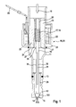
- the valve has a sleeve-shaped valve housing 11, in whose literallyess workedes end a valve body 12 and in its inlet end a not shown here Connecting piece for connecting a fluid line for the fluid inlet 10 is used fluid-tight.
- the valve body 12 is materially connected to the valve housing 11, wherein the material connection is symbolized by the weld 13.
- a metering or valve opening 14 is formed with a valve seat 15 surrounding the valve opening 14.
- valve needle 16 has at its valve opening 14 facing, literallyess districten needle end on a closing body 161 which forms a sealing seat with the valve seat 15.
- the closing body 161 is here formed like a ball and welded to the front end of the here massive valve needle 16. However, the closing body 161 can also be designed in one piece with the valve needle 16.
- the sealing seat 16 is produced or canceled by actuating the valve needle 16.
- the valve needle 16 is loaded to produce the sealing seat by a return member 18 to pressure and to cancel the sealing seat of an actuator 19 to train.
- the return member 18 is formed as a compression spring 17 and the actuator 19 as an electromagnet 20.
- other actuators 19 may be used, for. B. a piezoelectric or magnetostrictive actuator.
- the electromagnet 20 has in known manner a magnetic pot 21, a magnetic coil 22, a magnetic core 23 and a magnet armature 24.
- the magnet pot 21 is pushed onto the valve housing 11 and welded with its bottom of the pot on the valve housing 11 and takes the solenoid 22 axially immovable.
- the hollow cylindrical magnetic core 23 is positively inserted into the valve housing 11 and receives the compression spring 17 in the hollow core interior.
- the axially displaceably guided in the valve housing 11 Magentanker 24 is rigidly mounted on the valve needle 16, z. B. with this cohesively connected, resulting in FIG. 1 symbolized by the weld 35.
- the mutually facing annular end faces of armature 24 and magnetic core 23 include a working air gap 25 of the electromagnet 20 a.
- the compression spring 17 is supported on the one hand on the armature 24 and on the other hand on an adjustment sleeve 26 which is screwed into the magnetic core 23.
- flow channels 27 are held, which produce via the adjusting sleeve 26 a fluid connection from the inlet 10 to one of the valve opening 14 upstream, enclosed by the valve body 12 and the valve housing 11 valve chamber 28.
- the magnetic coil 22 is by means of an electric Connection plug 29 can be energized.
- the connecting piece for the fluid supply line and a connector housing 29 enclosing, not shown here plug housing are formed by a plastic casing which also at least partially surrounds the magnet pot 21 (not shown here).
- valve needle 16 two advantages are achieved in this valve, which also have valves with Vorhubfeder and Ankerkeweg, but in production and assembly are significantly more expensive.
- One advantage is the substantial elimination of the bumpers when closing the valve opening 14, ie during manufacture of the sealing seat, whereby the closing body remains after its first placement on the valve seat on this and ensures a reproducible metering of fluid by maintaining the sealing seat.
- the other advantage is the recovery of a so-called boost effect, d. H. a short-term acceleration of the armature 24 during valve opening, which leads to a reduction of the required magnetic force when lifting the sealing seat and allows a reduction in the power of the electromagnet 20.
- the valve needle 16 shown in the exemplary embodiments has different stiffnesses in the tensile and compressive directions in such a way that the valve needle 16 is almost invariably stiff when loaded in the direction of pull, but under load in the direction of pressure a stiffness permitting elastic deformations until a predetermined load is reached has and on the other hand assumes an increased stiffness after the occurrence of deformations.
- the predetermined load hereinafter referred to as buckling load, is preferably selected to be smaller than the sum of the minimum allowable restoring or closing force of the pressure acting on the valve needle 16 return member 18, so the pressure force of the compression spring 17, and the minimum existing closing force, the Fluid is exerted on the valve needle 16 with closing body 161.
- valve needle 16 in at least one needle section at least a pair of diametrically opposed deformation webs 30, which on reaching the predetermined load, so the buckling load, elastically on or buckle.
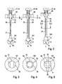
- FIG. 5 are in a needle portion of the valve needle 16 has two pairs of diametrically opposed each deformation webs 30.
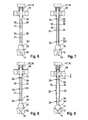
- FIG. 6 is in two axially successive needle portions of the valve needle 16 each have a pair of mutually opposite deformation webs 30 available.
- At least one slot 31 extending in the axial direction of the valve needle 16 with a limited slot length is introduced into the massive valve needle 16.
- the valve needle 16 has only one slot 31.
- the massive valve needle 16 can also be a hollow valve needle 16 are used, which has one or more slots 31 in the same way.
- the hollow valve needle 16 can be used for the fluid flow from the inlet 10 to the valve chamber 28, so that separate flow channels 27 can be omitted in the armature 24.
- the slot 31 can be cut into the hollow cylindrical valve needle 16, milled or pierced, as in FIG. 4 is shown.
- the valve needle 16 can also be rolled out of a metal sheet having at least two elongated recesses of limited axial length.
- the recesses are arranged so that when rolled sheet each two recesses are diametrically opposed to each other and form a valve needle 16 crossing slot 31.
- the parallel to the longitudinal edges of the Austanzungen extending joints of the sheet are materially connected to each other, for. B. welded.
- the electromagnet 20 as an actuator 19 can advantageously be dispensed with the stoffschüssige connection of the sheet and instead the rolled sheet on mutually averted ends with the closing body 161 and the armature 24 of the electromagnet 20 materially connected, z. B. on or welded, be.
- the hollow valve needle 16 are assembled from two bent sheets, wherein in each sheet at least one elongated recess is incorporated, the longitudinal edges extending parallel to the longitudinal edges of the sheet.
- the two bent sheets are placed against each other and cohesively connected to the abutting longitudinal edges together, z. B. welded.
- the recesses are arranged in the sheets, that two in the finished valve needle 16 each diametrically opposed recesses form a valve needle 16 crossing slot 31.
- the production of the recesses can be made by punching, cutting or milling.
- FIG. 2 is the behavior of the valve needle 16 schematically outlined with their different stiffnesses in the tensile and compressive direction during valve closing and valve opening.
- valve In FIG. 1 and Figure 2C the valve is open, that is lifted by energizing the electromagnet 20 of the closing body 161 from the valve seat 15.
- the valve needle 16 is loaded in the pulling direction and assumes its normal stretched rod shape.
- FIG. 2A the valve is closed.
- the electromagnet 20 is not energized, and the compression spring 17 presses the closing body 161 on the valve seat 15.
- the valve needle 16 is loaded under pressure, whereby due to the lower rigidity of the valve needle 16 in the pressure direction and the exceeding of the buckling load, the two deformation webs 30 are buckled inwardly and touch each other in the middle. By this support of the two deformation webs 30 together, the stiffness of the valve needle 16 is increased again in the pressure direction after deformation of the deformation webs 30 and the valve reliably kept closed with the valve opening 14 closed.
- the buckling of the deformation webs 30 according to FIG. 2A can be further supported by the deformation webs 30 are pre-bent by plastic deformation from its extended position by a few degrees inwards.
- the deformation webs 30 may buckle outward under load in the direction of compression and exceeding the buckling load, wherein the centers of the deformation webs 30 move away from each other.
- a buckling may e.g. be achieved in that the deformation webs 30 are pre-bent by plastic deformation from the extended position by a few degrees outwards.
- valve needle 16 In the embodiment of the valve needle 16 according to FIGS. 8 and 9 is the cross-sectional constriction 32 realized at each of the two slot ends by an inserted into the valve needle 16, circumferential groove 34 and the cross-sectional constriction 32 in the slot center by an inserted into the valve needle 16 transverse bore 33.
- grooves 34 and transverse bore 33 In this arrangement of grooves 34 and transverse bore 33, the deformation webs 30 buckle outwardly, as in FIG. 9 is shown.
- the rigidity of the valve needle 16 Upon reaching the maximum Ausknickung, ie the maximum distance of the deformation webs 30 in web center from each other, the rigidity of the valve needle 16 increases in the printing direction.
Abstract
Description
Die Erfindung geht aus von einem Ventil zum Zumessen von Fluid nach dem Oberbegriff des Anspruchs 1, wobei der für ein strömendes oder fließendes Medium stehende übergeordnete Begriff Fluid in Übereinstimmung mit der Strömungslehre für Gase und Flüssigkeiten verwendet wird.The invention is based on a valve for metering fluid according to the preamble of claim 1, wherein the standing for a flowing or flowing medium superordinate term fluid is used in accordance with the fluid flow theory for gases and liquids.
Bei einem bekannten Kraftstoffeinspritzventil (
Ein solches Ventil hat gegenüber einem Ventil mit starrer Verbindung von Anker und Ventilnadel den Vorteil, dass die bei Ventilbetätigung bewegte träge Masse auf zwei Teilmassen, nämlich auf Magnetanker und Ventilnadel mit Schließkörper, aufgeteilt ist, was zu einer Geräuschdämpfung beim Ventilöffnen und Ventilschließen führt. Darüber hinaus werden sog. Preller des Magnetankers durch die Vorhubfeder weitgehend gedämpft. Diese Preller führen beim Ventilschließen nach erstmaligem Aufsetzen des Schließkörpers auf den Ventilsitz zu erneutem Abheben des Schließkörpers vom Ventilsitz und damit zu einem unkontrollierten, kurzzeitigen Aufheben des Dichtsitzes und Öffnen des Ventils und damit zu einer nicht reproduzierbaren Zumessmenge von Fluid. Durch die Beweglichkeit des Magneten auf der Ventilnadel kann beim Ventilöffnen ein sog. mechanischer Boosteffekt dadurch erzielt, dass der Magnetanker bei Bestromung des Elektromagneten beschleunigt wird, bevor er nach Anschlagen an dem Mitnehmerflansch die Ventilnadel mitnimmt und den Schließkörper vom Ventilsitz abhebt. Durch den dabei stattfindenden Impulsaustausch zwischen Magnetanker und Ventilnadel wird insbesondere bei großem Fluiddruck die hydraulische Schließkraft am Schließkörper schnell überwunden. Der erforderliche Energiebedarf des Magneten ist damit geringer als bei Ventilen, bei denen Magnetanker und Ventilnadel starr miteinander verbunden sind.Such a valve has over a valve with rigid connection of armature and valve needle the advantage that the moving during valve actuated inertial mass is divided into two sub-masses, namely magnet armature and valve needle with closing body, resulting in a noise attenuation in valve opening and valve closing. In addition, so-called. Preller of the armature are largely attenuated by the Vorhubfeder. This Preller lead when valve closing after the first placement of the closing body on the valve seat to renewed lifting of the closing body from the valve seat and thus to an uncontrolled, short-term lifting of the sealing seat and opening the valve and thus to a non-reproducible Zumessmenge of fluid. Due to the mobility of the magnet on the valve needle, a so-called mechanical boost effect can be achieved during valve opening by accelerating the magnet armature when the electromagnet is energized, before lifting the valve needle after striking the driver flange and lifting the closing body from the valve seat. As a result of the momentum exchange between magnet armature and valve needle, the hydraulic closing force on the closing body is quickly overcome, especially in the case of high fluid pressure. The required energy requirement of the magnet is thus lower than in valves in which armature and valve needle are rigidly interconnected.
Weitere Ventile mit dem vorteilhaften sog. Ankerfreiweg sind aus
Das erfindungsgemäße Zumessventil mit den Merkmalen des Anspruchs 1 hat den Vorteil, dass durch die Ausbildung der Ventilnadel mit unterschiedlichen Steifigkeiten in Zug- und Druckrichtung die Vorteile der Ventile mit sog. Ankerfreiweg, wie Vermeidung von Prellern und mechanischer Booster, erhalten bleiben, ohne die Nachteile, die mit diesen bekannten konstruktiven Ausführungen dieser Ventile einhergehen, wie eine Vielzahl von Bauteilen und Verbindungsstellen, hohe Fertigungskosten, Abhängigkeit von Fertigungstoleranzen und verwendetem Fluid durch vorhandene hydraulische Quetschspalte, aufzuweisen. Die Anzahl der Bauteile bei dem erfindungsgemäßen Ventil ist nicht größer als bei Ventilen mit starrer Verbindung von Aktor und Ventilnadel, und entsprechend vereinfacht ist der Montageprozess. Da weniger funktionsbestimmende Toleranzen einzuhalten sind, wird der Fertigungsaufwand und die Exemplarstreuung in den Funktionswerten, insbesondere bei der Mengenzumessung von Fluid, reduziert. Die Funktion des Ventils bleibt über die Laufzeit stabil. Die bei den bekannten Ventilen durch Vorhubfeder und Ankerfreiweg erzielten Vorteile, wie Dämpfung der Preller und mechanische Boosterung, werden durch die von der Rückstell- oder Schließkraft des Rückstellorgans ausgelöste elastische Verformung der Ventilnadel bei Aufsetzen des Schließkörpers auf den Ventilsitz und durch selbständiges Rückstellen der Verformung der Ventilnadel bei erfolgter Aufhebung der Rückstellkraft des Rückstellorgans durch den aktivierten Aktor erzielt. Durch die bis zu einer vorbestimmten Last geringe Steifigkeit der Ventilnadel werden Preller beim Ventilschließen vermieden, da der Schließkörper nach dem ersten Schließen des Ventils auf dem Ventilsitz verbleibt, während die träge Masse des Aktors aufgrund der Verformungen der Ventilnadel noch schwingen und dadurch ihre Energie abbauen kann. Ist der Aktor ein Elektromagnet mit einem im Fluid sich bewegenden Magnetanker, so wird durch die Bewegung des Magnetankers im Fluid weitere Energie abgebaut. Nach Eintreten der maximalen Verformung wird durch die nunmehr wieder höhere Steifigkeit der Ventilnadel der Schließkörper definiert auf dem Ventilsitz gehalten, so dass eine definierte Zuordnung von Aktor und Ventilnadel gewährleistet ist, so z.B. der Arbeitsluftspalt des Elektromagneten zwischen Magnetanker und Magnetkern bei geschlossenem Ventil unabhängig von Toleranzen des Rückstellorgans konstant ist.The metering valve according to the invention with the features of claim 1 has the advantage that the advantages of the valves with so-called. Ankerfreiweg, such as avoid bouncing and mechanical booster, preserved by the formation of the valve needle with different stiffness in the tension and compression direction, without the disadvantages associated with these known structural designs of these valves, such as a variety of components and joints, high manufacturing costs, dependency on manufacturing tolerances and fluid used by existing hydraulic crimp, exhibit. The number of components in the valve according to the invention is not greater than for valves with a rigid connection Actuator and valve needle, and accordingly simplifies the assembly process. Since less function-determining tolerances are to be observed, the production costs and the sample spread in the functional values, in particular in the quantitative metering of fluid, are reduced. The function of the valve remains stable over the runtime. The advantages achieved in the known valves by Vorhubfeder and Ankerfreiweg, such as damping of the Preller and mechanical Boosterung are triggered by the return or closing force of the return member elastic deformation of the valve needle when placing the closing body on the valve seat and by self-resetting the deformation Valve needle scored by successful cancellation of the restoring force of the return actuator by the activated actuator. By up to a predetermined load low stiffness of the valve needle Preller are avoided when valve closing, since the closing body after the first closing of the valve remains on the valve seat, while the inertial mass of the actuator due to the deformations of the valve needle still swing and thereby reduce their energy , If the actuator is an electromagnet with a magnet armature moving in the fluid, further energy is dissipated by the movement of the magnet armature in the fluid. After the maximum deformation has occurred, the closure body is held in a defined manner on the valve seat by the now higher stiffness of the valve needle, so that a defined assignment of actuator and valve needle is ensured, for example the working air gap of the electromagnet between magnet armature and magnet core with closed valve, independent of tolerances of the return member is constant.
Durch die in den weiteren Ansprüchen aufgeführten Maßnahmen sind vorteilhafte Weiterbildungen und Verbesserungen des im Anspruch 1 angegebenen Ventils möglich.The measures listed in the further claims advantageous refinements and improvements of the claim 1 valve are possible.
Gemäß einer vorteilhaften Ausführungsform der Erfindung ist die vorbestimmte Last, ab der elastische Verformungen der Ventilnadel auftreten, kleiner gewählt, als die Summe aus minimal zulässiger Rückstell- oder Schließkraft des in Druckrichtung auf die Ventilnadel wirkenden Rückstellorgans und einer minimal vorhandenen Schließkraft, die vom Fluid auf die Ventilnadel mit Schließkörper ausgeübt wird. Bei demgegenüber auf die Ventilnadel in Druckrichtung wirkenden größeren Schließkräften tritt die elastische Verformung der Ventilnadel ein. Damit ist die Anfangsposition des mit der Ventilnadel verbunden Aktors beim Ventilschließen, z.B. die Anfangsposition des Magnetankers eines Elektromagneten, unabhängig von der auf die Ventilnadel in Druckrichtung wirkenden Rückstellkraft des Rückstellorgans genau definiert. Durch die mit zunehmender Verformung sich erhöhende Steifigkeit der Ventilnadel wird der Schließkörper stärker auf dem Ventilsitz aufgepresst, so dass im Ruhezustand des geschlossenen Ventils eine definierte Zuordnung von Aktor und Ventilnadel gewährleistet ist, so z.B. stets ein konstanter Arbeitsluftspalt zwischen Magnetanker und Magnetkern des Elektromagneten vorhanden ist.According to an advantageous embodiment of the invention, the predetermined load from which elastic deformations of the valve needle occur, chosen smaller than the sum of the minimum allowable restoring or closing force acting in the pressure direction on the valve needle return member and a minimum existing closing force of the fluid the valve needle is exerted with closing body. In contrast, acting on the valve needle in the compression direction greater closing forces occurs elastic deformation of the valve needle one. Thus, the initial position of the actuator connected to the valve needle valve closing, for example, the initial position of the armature of an electromagnet, regardless of the force acting on the valve needle in the pressure direction restoring force of the return member is precisely defined. Due to the increasing deformation with increasing stiffness of the valve needle, the closing body is pressed more strongly on the valve seat, so that a defined assignment of actuator and valve needle is ensured in the idle state of the closed valve, such as always a constant working air gap between the armature and magnetic core of the solenoid is present ,
Gemäß einer vorteilhaften Ausführungsform der Erfindung weist die Ventilnadel in mindestens einem Nadelabschnitt mindestens ein Paar Verformungsstege auf, die einander diametral gegenüberliegen und bei Erreichen der vorbestimmten Last elastisch ein- oder ausknicken.According to an advantageous embodiment of the invention, the valve needle in at least one needle section at least a pair of deformation webs which are diametrically opposed to each other and elastically on reaching the predetermined load or buckle.
Die Verformungsstege werden in fertigungstechnisch vorteilhafter Weise dadurch gewonnen, dass in die massive oder hohle Ventilnadel in mindestens einem Nadelabschnitt mindestens ein in Achsrichtung der Ventilnadel sich erstreckender Schlitz mit begrenzter Schlitzlänge eingebracht wird. Alternativ kann zur Gewinnung der Verformungsstege eine hohle Ventilnadel aus einem Blech mit mindestens zwei vorzugsweise ausgestanzten Aussparungen von begrenzter Axiallänge gerollt werden, wobei zwei in der hohlen Ventilnadel jeweils einander diametral gegenüberliegenden Aussparungen einen Schlitz bilden. Vorzugsweise werden die parallel zu den Längskanten sich erstreckenden Stoßstellen des Blechs miteinander stoffschlüssig verbunden, z.B. verschweißt. Bei Verwendung eines Elektromagneten als Aktor wird vorteilhaft auf eine solche Verschweißung verzichtet und Schließkörper und Magnetanker des Elektromagneten auf die Stirnenden des gerollten Blechs aufgeschweißt. Auch kann zur Gewinnung der Verformungsstege eine hohle Ventilnadel aus zwei gebogenen Blechen zusammengesetzt werden, die jeweils mindestens eine parallel zu den Längskanten des Blechs sich erstreckende, vorzugsweise ausgestanzte Aussparung von begrenzter Axiallänge aufweisen und an den aneinanderstoßenden Längskanten miteinander stoffschlüssig verbunden sind, so dass wiederum zwei in der hohlen Ventilnadel jeweils einander diametral gegenüberliegende Aussparungen einen Schlitz bilden.The deformation webs are advantageously obtained in manufacturing technology in that in the solid or hollow valve needle in at least one needle section at least one in the axial direction of the valve needle extending slot is introduced with a limited slot length. Alternatively, to obtain the deformation webs, a hollow valve needle can be rolled out of a metal sheet with at least two preferably punched-out recesses of limited axial length, wherein two recesses each diametrically opposed in the hollow valve needle form a slot. Preferably, the parallel to the longitudinal edges extending joints of the sheet are materially connected to each other, eg welded. When using an electromagnet as an actuator is advantageously dispensed with such welding and welded closing body and armature of the electromagnet on the front ends of the rolled sheet. Also, to obtain the deformation webs, a hollow valve needle of two bent sheets are assembled, each having at least one parallel to the longitudinal edges of the sheet extending, preferably punched recess of limited axial length and are integrally connected to the abutting longitudinal edges together so that in turn two in the hollow valve needle each diametrically opposed recesses form a slot.
Ein gerichtetes Ein- oder Ausknicken der Veformungsstege wird gemäß einer vorteilhaften Ausführungsform der Erfindung durch Gelenkstellen bestimmt und unterstützt, die an den Schlitzenden und in Schlitzmitte des mindestens einen Schlitzes in die Ventilnadel eingearbeitet und vorzugsweise durch Querschnittsverengungen in den Verformungsstegen gebildet sind.A directed buckling or buckling of the Veformungsstege is determined and supported according to an advantageous embodiment of the invention by joints, which are incorporated at the slot ends and in the slot center of at least one slot in the valve needle and preferably formed by cross-sectional constrictions in the deformation webs.
Werden die Querschnittsverengungen gemäß einer vorteilhaften Ausführungsform der Erfindung durch je eine in die Ventilnadel eingebrachte Querbohrung an jedem der beiden Schlitzenden und durch eine in die Ventilnadel eingebrachte, umlaufende Nut in Schlitzmitte realisiert, so knicken die Verformungsstege bei Überschreiten der vorbestimmten Last, der sog. Knicklast, nach innen ein und stützen sich aneinander ab. Durch die gegenseitige Abstützung erhöht sich die Steifigkeit der Ventilnadel in Druckrichtung.If the cross-sectional constrictions are realized in accordance with an advantageous embodiment of the invention by a respective inserted into the valve needle transverse bore at each of the two slot ends and introduced into the valve needle, circumferential groove in slot center, so buckle the deformation webs when exceeding the predetermined load, the so-called. Buckling load , inside and support each other. The mutual support increases the rigidity of the valve needle in the pressure direction.
Das Einknicken der Verformungsstege nach innen kann gemäß einer alternativen Ausführungsform der Erfindung auch dadurch erzielt werden, dass die Verformungsstege durch plastische Verformung aus ihrer Strecklage um wenige Grade nach innen vorgebogen sind.The buckling of the deformation webs inward according to an alternative embodiment of the invention can also be achieved in that the deformation webs are pre-bent by plastic deformation from its extended position by a few degrees inwards.
Werden die Querschnittsverengungen gemäß einer vorteilhaften Ausführungsform der Erfindung durch je eine in die Ventilnadel eingebrachte, umlaufende Nut an den Schlitzenden und durch eine in die Ventilnadel eingebrachte Querbohrung in Schlitzmitte realisiert, so knickern die Verformungsstege bei Überschreiten der Knicklast nach außen aus. Bei Erreichen eines maximalen Abstands der Mitten der Verformungsstege voneinander, erhöht sich die Steifigkeit der Ventilnadel in Druckrichtung.If the cross-sectional constrictions are realized according to an advantageous embodiment of the invention by a respective inserted into the valve needle, circumferential groove at the slot ends and introduced into the valve needle transverse bore in slot center, so buckle the deformation webs when exceeding the buckling load to the outside. When reaching a maximum distance of the centers of the deformation webs from each other, the rigidity of the valve needle increases in the printing direction.
Das Ausknicken der Verformungsstege nach außen kann gemäß einer alternativen Ausführungsform der Erfindung auch dadurch gefördert werden, dass die Verformungsstege durch plastische Verformung aus der Strecklage um wenige Grade nach außen vorgebogen sind.The buckling of the deformation webs to the outside can also be promoted according to an alternative embodiment of the invention in that the deformation webs are pre-bent by plastic deformation from the extended position by a few degrees outwards.
Die Erfindung ist anhand von in den Zeichnungen dargestellten Ausführungsbeispielen in der nachfolgenden Beschreibung näher erläutert. Es zeigen:
-
Figur 1 einen Längsschnitt eines Ventils zum Zumessen von Fluid im Betriebszustand "Ventil offen" mit einem Aktor und einem Rückstellorgan zur Betätigung einer Ventilnadel, -
Figur 2 eine schematisierte Darstellung von Ventilnadel, Aktor und Rückstellorgan bei geschlossenem Ventil im Ruhezustand (Figur 2A ), bei geschlossenem Ventil und aktiviertem Aktor (Figur 2B ) und bei geöffnetem Ventil und aktiviertem Aktor (Figur 2C ), -
Figur 3 einen Querschnitt der Ventilnadel gemäß Linie III - III inFigur 2C, Figur 4 eine gleiche Darstellung wie inFigur 3 eines weiteren Ausführungsbeispiels der Ventilnadel, -
Figur 5 eine gleiche Darstellung wie inFigur 3 eines weiteren Ausführungsbeispiels der Ventilnadel, -
Figur 6 eine gleiche Darstellung wie inFigur 2C gemäß einem weiteren Ausführungsbeispiel der Ventilnadel, -
Figur 7 eine gleiche Darstellung wie inFigur 2C gemäß einem weiteren Ausführungsbeispiel der Ventilnadel, -
Figur 8 eine gleiche Darstellung wie inFigur 2C gemäß einem weiteren Ausführungsbeispiel der Ventilnadel, -
Figur 9 die Ventilnadel gemäßFigur 8 bei geschlossenem Ventil in Ruhestellung.
-
FIG. 1 a longitudinal section of a valve for metering fluid in the operating state "valve open" with an actuator and a return member for actuating a valve needle, -
FIG. 2 a schematic representation of the valve needle, actuator and return member with the valve closed at rest (FIG. 2A ), with closed valve and activated actuator (FIG. 2B ) and with open valve and activated actuator (Figure 2C ) -
FIG. 3 a cross section of the valve needle according to line III - III inFIG. 2C, FIG. 4 a same representation as inFIG. 3 a further embodiment of the valve needle, -
FIG. 5 a same representation as inFIG. 3 a further embodiment of the valve needle, -
FIG. 6 a same representation as inFigure 2C according to a further embodiment of the valve needle, -
FIG. 7 a same representation as inFigure 2C according to a further embodiment of the valve needle, -
FIG. 8 a same representation as inFigure 2C according to a further embodiment of the valve needle, -
FIG. 9 the valve needle according toFIG. 8 when the valve is closed, at rest.
Das in
Der Elektromagnet 20 weist in bekannter Weise einen Magnettopf 21, eine Magnetspule 22, einen Magnetkern 23 und einen Magnetanker 24 auf. Der Magnettopf 21 ist auf das Ventilgehäuse 11 aufgeschoben und mit seinem Topfboden am Ventilgehäuse 11 verschweißt und nimmt die Magnetspule 22 axial unverschieblich auf. Der hohlzylindrische Magnetkern 23 ist formschlüssig in das Ventilgehäuse 11 eingesetzt und nimmt im hohlen Kerninnern die Druckfeder 17 auf. Der im Ventilgehäuse 11 axial verschieblich geführte Magentanker 24 ist starr auf der Ventilnadel 16 befestigt, z. B. mit dieser stoffschlüssig verbunden, was in
Mit verschiedenen, im Folgenden erläuterten konstruktiven Ausführungen der Ventilnadel 16 werden bei diesem Ventil zwei Vorteile erzielt, die auch Ventile mit Vorhubfeder und Ankerfreiweg aufweisen, die aber in Fertigung und Montage deutlich aufwendiger sind. Der eine Vorteil ist die weitgehende Eliminierung der Preller beim Schließen der Ventilöffnung 14, also beim Herstellen des Dichtsitzes, wodurch der Schließkörper nach seinem ersten Aufsetzen auf den Ventilsitz auf diesem verbleibt und durch Aufrechterhaltung des Dichtsitzes eine reproduzierbare Zumessung von Fluid sicherstellt. Der andere Vorteil ist die Gewinnung eines sog. Boosteffekts, d. h. einer kurzzeitigen Beschleunigung des Magnetankers 24 beim Ventilöffnen, was zu einer Verringerung der erforderlichen Magnetkraft beim Aufheben des Dichtsitzes führt und eine Reduzierung der Leistung des Elektromagneten 20 ermöglicht. Die in den Ausführungsbeispielen gezeigte Ventilnadel 16 weist hierzu in Zug- und Druckrichtung unterschiedliche Steifigkeiten in der Weise auf, dass die Ventilnadel 16 bei Belastung in Zugrichtung quasi unverformbar steif ist, bei Belastung in Druckrichtung jedoch eine bis zum Erreichen einer vorbestimmten Last elastische Verformungen zulassende Steifigkeit aufweist und nach Eintreten der Verformungen eine demgegenüber vergrößerte Steifigkeit annimmt. Die vorbestimmte Last, im Folgenden als Knicklast bezeichnet, ist vorzugsweise kleiner gewählt als die Summe aus minimal zulässiger Rückstell- oder Schließkraft des in Druckrichtung auf die Ventilnadel 16 wirkenden Rückstellorgans 18, also der Druckkraft der Druckfeder 17, und der minimal vorhandenen Schließkraft, die vom Fluid auf die Ventilnadel 16 mit Schließkörper 161 ausgeübt wird. Diese unterschiedlichen Steifigkeiten werden in konstruktiv einfacher Weise dadurch erreicht, dass die Ventilnadel 16 in mindestens einem Nadelabschnitt mindestens ein Paar einander diametral gegenüberliegende Verformungsstege 30 aufweist, die bei Erreichen der vorbestimmten Last, also der Knicklast, elastisch ein- oder ausknicken.With different, explained below constructive embodiments of the
Im Ausführungsbeispiel der
Zur Gewinnung dieser Verformungsstege 30 ist in die massive Ventilnadel 16 mindestens ein sich in Achsrichtung der Ventilnadel 16 erstreckender Schlitz 31 mit begrenzter Schlitzlänge eingebracht. In dem Ausführungsbeispiel der
Anstelle der massiven Ventilnadel 16 gemäß
In
In
In
Wird in der Ventilschließstellung nunmehr der Elektromagnet 20 bestromt, wie dies in
Das Einknicken der Verformungsstege 30 gemäß
Alternativ können die Verformungsstege 30 bei Belastung in Druckrichtung und Überschreiten der Knicklast auch nach außen ausknicken, wobei sich die Mitten der Verformungsstege 30 voneinander wegbewegen. Eine solche Ausknickung kann z.B. dadurch erreicht werden, dass die Verformungsstege 30 durch plastische Verformung aus der Strecklage um wenige Grade nach außen vorgebogen werden.Alternatively, the
Um ein definiertes, gerichtetes Ein- oder Ausknicken der Verformungsstege 30 zu gewährleisten, sind an den beiden Schlitzenden und in Schlitzmitte eines jeden Schlitzes 31 Gelenkstellen in die Ventilnadel 16 eingearbeitet, die durch Querschnittsverengungen 32 in den Verformungsstegen 30, also durch eine Reduzierung des Querschnitts des Verformungsstegmaterials, erzielt werden. Im Ausführungsbeispiel der Ventilnadel 16 gemäß
In dem Ausführungsbeispiel der Ventilnadel 16 gemäß
Claims (13)
Applications Claiming Priority (1)
| Application Number | Priority Date | Filing Date | Title |
|---|---|---|---|
| DE102012208136A DE102012208136A1 (en) | 2012-05-15 | 2012-05-15 | Valve for metering fluid |
Publications (2)
| Publication Number | Publication Date |
|---|---|
| EP2664779A1 true EP2664779A1 (en) | 2013-11-20 |
| EP2664779B1 EP2664779B1 (en) | 2016-01-20 |
Family
ID=48044597
Family Applications (1)
| Application Number | Title | Priority Date | Filing Date |
|---|---|---|---|
| EP13160890.3A Active EP2664779B1 (en) | 2012-05-15 | 2013-03-25 | Valve for metering out fluid |
Country Status (2)
| Country | Link |
|---|---|
| EP (1) | EP2664779B1 (en) |
| DE (1) | DE102012208136A1 (en) |
Cited By (5)
| Publication number | Priority date | Publication date | Assignee | Title |
|---|---|---|---|---|
| WO2016096217A1 (en) * | 2014-12-18 | 2016-06-23 | Robert Bosch Gmbh | Injection nozzle for fuels |
| WO2016207268A1 (en) * | 2015-06-24 | 2016-12-29 | Robert Bosch Gmbh | Valve for metering a fluid |
| WO2017005556A1 (en) * | 2015-07-03 | 2017-01-12 | Robert Bosch Gmbh | Injection nozzle for a fuel injection system |
| WO2019016042A1 (en) * | 2017-07-18 | 2019-01-24 | L'orange Gmbh | Nozzle needle for a fuel injector, fuel injector, and injection system for an internal combustion engine |
| WO2021090388A1 (en) * | 2019-11-06 | 2021-05-14 | 三菱電機株式会社 | Fuel injection valve |
Families Citing this family (1)
| Publication number | Priority date | Publication date | Assignee | Title |
|---|---|---|---|---|
| DE102016225939A1 (en) | 2016-12-22 | 2018-06-28 | Robert Bosch Gmbh | Electromagnetically actuated valve and method for producing a valve needle for an electromagnetically operable valve |
Citations (2)
| Publication number | Priority date | Publication date | Assignee | Title |
|---|---|---|---|---|
| WO1996009473A1 (en) * | 1994-09-20 | 1996-03-28 | Siemens Automotive Corporation | Notched needle bounce eliminator |
| DE102011078732A1 (en) * | 2011-07-06 | 2013-01-10 | Robert Bosch Gmbh | Device for injecting fuel, has valve needle and valve housing with valve seat, where valve needle closes aperture in valve seat, and valve needle has area with reduced rigidity |
Family Cites Families (4)
| Publication number | Priority date | Publication date | Assignee | Title |
|---|---|---|---|---|
| DE19849210A1 (en) | 1998-10-26 | 2000-04-27 | Bosch Gmbh Robert | Fuel injection valve for internal combustion engine fuel injection system has armature movable between two stops, damping spring arranged between second stop and armature |
| DE19932763A1 (en) | 1999-07-14 | 2001-01-18 | Bosch Gmbh Robert | Fuel injector |
| DE19946602A1 (en) | 1999-09-29 | 2001-04-12 | Bosch Gmbh Robert | Fuel injector |
| DE10108945A1 (en) | 2001-02-24 | 2002-09-05 | Bosch Gmbh Robert | Fuel injector |
-
2012
- 2012-05-15 DE DE102012208136A patent/DE102012208136A1/en not_active Withdrawn
-
2013
- 2013-03-25 EP EP13160890.3A patent/EP2664779B1/en active Active
Patent Citations (2)
| Publication number | Priority date | Publication date | Assignee | Title |
|---|---|---|---|---|
| WO1996009473A1 (en) * | 1994-09-20 | 1996-03-28 | Siemens Automotive Corporation | Notched needle bounce eliminator |
| DE102011078732A1 (en) * | 2011-07-06 | 2013-01-10 | Robert Bosch Gmbh | Device for injecting fuel, has valve needle and valve housing with valve seat, where valve needle closes aperture in valve seat, and valve needle has area with reduced rigidity |
Cited By (8)
| Publication number | Priority date | Publication date | Assignee | Title |
|---|---|---|---|---|
| WO2016096217A1 (en) * | 2014-12-18 | 2016-06-23 | Robert Bosch Gmbh | Injection nozzle for fuels |
| US10508634B2 (en) | 2014-12-18 | 2019-12-17 | Robert Bosch Gmbh | Injection nozzle for fuels |
| WO2016207268A1 (en) * | 2015-06-24 | 2016-12-29 | Robert Bosch Gmbh | Valve for metering a fluid |
| JP2018518629A (en) * | 2015-06-24 | 2018-07-12 | ローベルト ボッシュ ゲゼルシャフト ミット ベシュレンクテル ハフツング | Valve for metering fluid |
| US10519909B2 (en) | 2015-06-24 | 2019-12-31 | Robert Bosch Gmbh | Valve for metering a fluid |
| WO2017005556A1 (en) * | 2015-07-03 | 2017-01-12 | Robert Bosch Gmbh | Injection nozzle for a fuel injection system |
| WO2019016042A1 (en) * | 2017-07-18 | 2019-01-24 | L'orange Gmbh | Nozzle needle for a fuel injector, fuel injector, and injection system for an internal combustion engine |
| WO2021090388A1 (en) * | 2019-11-06 | 2021-05-14 | 三菱電機株式会社 | Fuel injection valve |
Also Published As
| Publication number | Publication date |
|---|---|
| DE102012208136A1 (en) | 2013-11-21 |
| EP2664779B1 (en) | 2016-01-20 |
Similar Documents
| Publication | Publication Date | Title |
|---|---|---|
| EP2664779B1 (en) | Valve for metering out fluid | |
| DE19957172A1 (en) | Fuel injector | |
| EP3478957B1 (en) | Valve for injecting gaseous fuel | |
| WO2013164131A1 (en) | Valve for metering fluid | |
| DE10118162C2 (en) | Fuel injector | |
| WO2013189690A1 (en) | Injection valve | |
| DE102005043969B4 (en) | Valve device for controlling a fluid flow | |
| EP3698383B1 (en) | Electromagnetic actuator device and use of such a device | |
| DE102014220877B3 (en) | Fuel injection valve | |
| DE102016220912A1 (en) | Fuel injection valve | |
| DE102004013413B4 (en) | Fuel injection valve | |
| WO2012034742A1 (en) | Normally closed magnetic valve | |
| EP2616294A1 (en) | Normally closed magnetic valve | |
| EP2864623B1 (en) | Injection valve | |
| EP3141737B1 (en) | Valve for metering a fluid | |
| DE102018200364A1 (en) | Valve for metering a fluid | |
| EP3545185B1 (en) | Gas dosing valve | |
| EP2472096A1 (en) | Injection valve for injecting a fluid | |
| DE102004057573A1 (en) | Hydraulic three way directional control valve, has actuating unit including magnetic core that is partially arranged inside coil of actuating unit, and valve unit operatively connected to actuating unit | |
| EP3387247B1 (en) | Electromagnetically actuatable inlet valve and high-pressure pump having an inlet valve | |
| DE10118161B9 (en) | Fuel injector | |
| DE102013223453A1 (en) | Valve for metering fluid | |
| DE102016225769A1 (en) | Valve for metering a fluid | |
| DE102015220677A1 (en) | Electromagnetically actuated inlet valve and high-pressure pump with inlet valve | |
| DE102015209395A1 (en) | fuel injector |
Legal Events
| Date | Code | Title | Description |
|---|---|---|---|
| PUAI | Public reference made under article 153(3) epc to a published international application that has entered the european phase |
Free format text: ORIGINAL CODE: 0009012 |
|
| AK | Designated contracting states |
Kind code of ref document: A1 Designated state(s): AL AT BE BG CH CY CZ DE DK EE ES FI FR GB GR HR HU IE IS IT LI LT LU LV MC MK MT NL NO PL PT RO RS SE SI SK SM TR |
|
| AX | Request for extension of the european patent |
Extension state: BA ME |
|
| 17P | Request for examination filed |
Effective date: 20140520 |
|
| RBV | Designated contracting states (corrected) |
Designated state(s): AL AT BE BG CH CY CZ DE DK EE ES FI FR GB GR HR HU IE IS IT LI LT LU LV MC MK MT NL NO PL PT RO RS SE SI SK SM TR |
|
| GRAP | Despatch of communication of intention to grant a patent |
Free format text: ORIGINAL CODE: EPIDOSNIGR1 |
|
| INTG | Intention to grant announced |
Effective date: 20151007 |
|
| GRAS | Grant fee paid |
Free format text: ORIGINAL CODE: EPIDOSNIGR3 |
|
| GRAA | (expected) grant |
Free format text: ORIGINAL CODE: 0009210 |
|
| AK | Designated contracting states |
Kind code of ref document: B1 Designated state(s): AL AT BE BG CH CY CZ DE DK EE ES FI FR GB GR HR HU IE IS IT LI LT LU LV MC MK MT NL NO PL PT RO RS SE SI SK SM TR |
|
| REG | Reference to a national code |
Ref country code: GB Ref legal event code: FG4D Free format text: NOT ENGLISH |
|
| REG | Reference to a national code |
Ref country code: CH Ref legal event code: EP |
|
| REG | Reference to a national code |
Ref country code: IE Ref legal event code: FG4D Free format text: LANGUAGE OF EP DOCUMENT: GERMAN |
|
| REG | Reference to a national code |
Ref country code: AT Ref legal event code: REF Ref document number: 771850 Country of ref document: AT Kind code of ref document: T Effective date: 20160215 |
|
| REG | Reference to a national code |
Ref country code: DE Ref legal event code: R096 Ref document number: 502013001833 Country of ref document: DE |
|
| REG | Reference to a national code |
Ref country code: FR Ref legal event code: PLFP Year of fee payment: 4 |
|
| REG | Reference to a national code |
Ref country code: LT Ref legal event code: MG4D Ref country code: NL Ref legal event code: MP Effective date: 20160120 |
|
| PGFP | Annual fee paid to national office [announced via postgrant information from national office to epo] |
Ref country code: FR Payment date: 20160322 Year of fee payment: 4 |
|
| PG25 | Lapsed in a contracting state [announced via postgrant information from national office to epo] |
Ref country code: NL Free format text: LAPSE BECAUSE OF FAILURE TO SUBMIT A TRANSLATION OF THE DESCRIPTION OR TO PAY THE FEE WITHIN THE PRESCRIBED TIME-LIMIT Effective date: 20160120 |
|
| PG25 | Lapsed in a contracting state [announced via postgrant information from national office to epo] |
Ref country code: NO Free format text: LAPSE BECAUSE OF FAILURE TO SUBMIT A TRANSLATION OF THE DESCRIPTION OR TO PAY THE FEE WITHIN THE PRESCRIBED TIME-LIMIT Effective date: 20160420 Ref country code: GR Free format text: LAPSE BECAUSE OF FAILURE TO SUBMIT A TRANSLATION OF THE DESCRIPTION OR TO PAY THE FEE WITHIN THE PRESCRIBED TIME-LIMIT Effective date: 20160421 Ref country code: ES Free format text: LAPSE BECAUSE OF FAILURE TO SUBMIT A TRANSLATION OF THE DESCRIPTION OR TO PAY THE FEE WITHIN THE PRESCRIBED TIME-LIMIT Effective date: 20160120 Ref country code: HR Free format text: LAPSE BECAUSE OF FAILURE TO SUBMIT A TRANSLATION OF THE DESCRIPTION OR TO PAY THE FEE WITHIN THE PRESCRIBED TIME-LIMIT Effective date: 20160120 Ref country code: FI Free format text: LAPSE BECAUSE OF FAILURE TO SUBMIT A TRANSLATION OF THE DESCRIPTION OR TO PAY THE FEE WITHIN THE PRESCRIBED TIME-LIMIT Effective date: 20160120 |
|
| PG25 | Lapsed in a contracting state [announced via postgrant information from national office to epo] |
Ref country code: LV Free format text: LAPSE BECAUSE OF FAILURE TO SUBMIT A TRANSLATION OF THE DESCRIPTION OR TO PAY THE FEE WITHIN THE PRESCRIBED TIME-LIMIT Effective date: 20160120 Ref country code: IS Free format text: LAPSE BECAUSE OF FAILURE TO SUBMIT A TRANSLATION OF THE DESCRIPTION OR TO PAY THE FEE WITHIN THE PRESCRIBED TIME-LIMIT Effective date: 20160520 Ref country code: SE Free format text: LAPSE BECAUSE OF FAILURE TO SUBMIT A TRANSLATION OF THE DESCRIPTION OR TO PAY THE FEE WITHIN THE PRESCRIBED TIME-LIMIT Effective date: 20160120 Ref country code: LT Free format text: LAPSE BECAUSE OF FAILURE TO SUBMIT A TRANSLATION OF THE DESCRIPTION OR TO PAY THE FEE WITHIN THE PRESCRIBED TIME-LIMIT Effective date: 20160120 Ref country code: PT Free format text: LAPSE BECAUSE OF FAILURE TO SUBMIT A TRANSLATION OF THE DESCRIPTION OR TO PAY THE FEE WITHIN THE PRESCRIBED TIME-LIMIT Effective date: 20160520 Ref country code: RS Free format text: LAPSE BECAUSE OF FAILURE TO SUBMIT A TRANSLATION OF THE DESCRIPTION OR TO PAY THE FEE WITHIN THE PRESCRIBED TIME-LIMIT Effective date: 20160120 Ref country code: PL Free format text: LAPSE BECAUSE OF FAILURE TO SUBMIT A TRANSLATION OF THE DESCRIPTION OR TO PAY THE FEE WITHIN THE PRESCRIBED TIME-LIMIT Effective date: 20160120 Ref country code: BE Free format text: LAPSE BECAUSE OF NON-PAYMENT OF DUE FEES Effective date: 20160331 |
|
| PGFP | Annual fee paid to national office [announced via postgrant information from national office to epo] |
Ref country code: IT Payment date: 20160331 Year of fee payment: 4 |
|
| REG | Reference to a national code |
Ref country code: DE Ref legal event code: R097 Ref document number: 502013001833 Country of ref document: DE |
|
| PG25 | Lapsed in a contracting state [announced via postgrant information from national office to epo] |
Ref country code: LU Free format text: LAPSE BECAUSE OF FAILURE TO SUBMIT A TRANSLATION OF THE DESCRIPTION OR TO PAY THE FEE WITHIN THE PRESCRIBED TIME-LIMIT Effective date: 20160325 Ref country code: DK Free format text: LAPSE BECAUSE OF FAILURE TO SUBMIT A TRANSLATION OF THE DESCRIPTION OR TO PAY THE FEE WITHIN THE PRESCRIBED TIME-LIMIT Effective date: 20160120 Ref country code: EE Free format text: LAPSE BECAUSE OF FAILURE TO SUBMIT A TRANSLATION OF THE DESCRIPTION OR TO PAY THE FEE WITHIN THE PRESCRIBED TIME-LIMIT Effective date: 20160120 Ref country code: MC Free format text: LAPSE BECAUSE OF FAILURE TO SUBMIT A TRANSLATION OF THE DESCRIPTION OR TO PAY THE FEE WITHIN THE PRESCRIBED TIME-LIMIT Effective date: 20160120 |
|
| REG | Reference to a national code |
Ref country code: CH Ref legal event code: PL |
|
| PLBE | No opposition filed within time limit |
Free format text: ORIGINAL CODE: 0009261 |
|
| STAA | Information on the status of an ep patent application or granted ep patent |
Free format text: STATUS: NO OPPOSITION FILED WITHIN TIME LIMIT |
|
| PG25 | Lapsed in a contracting state [announced via postgrant information from national office to epo] |
Ref country code: CZ Free format text: LAPSE BECAUSE OF FAILURE TO SUBMIT A TRANSLATION OF THE DESCRIPTION OR TO PAY THE FEE WITHIN THE PRESCRIBED TIME-LIMIT Effective date: 20160120 Ref country code: RO Free format text: LAPSE BECAUSE OF FAILURE TO SUBMIT A TRANSLATION OF THE DESCRIPTION OR TO PAY THE FEE WITHIN THE PRESCRIBED TIME-LIMIT Effective date: 20160120 Ref country code: SM Free format text: LAPSE BECAUSE OF FAILURE TO SUBMIT A TRANSLATION OF THE DESCRIPTION OR TO PAY THE FEE WITHIN THE PRESCRIBED TIME-LIMIT Effective date: 20160120 Ref country code: SK Free format text: LAPSE BECAUSE OF FAILURE TO SUBMIT A TRANSLATION OF THE DESCRIPTION OR TO PAY THE FEE WITHIN THE PRESCRIBED TIME-LIMIT Effective date: 20160120 |
|
| 26N | No opposition filed |
Effective date: 20161021 |
|
| REG | Reference to a national code |
Ref country code: IE Ref legal event code: MM4A |
|
| PG25 | Lapsed in a contracting state [announced via postgrant information from national office to epo] |
Ref country code: LI Free format text: LAPSE BECAUSE OF NON-PAYMENT OF DUE FEES Effective date: 20160331 Ref country code: IE Free format text: LAPSE BECAUSE OF NON-PAYMENT OF DUE FEES Effective date: 20160325 Ref country code: CH Free format text: LAPSE BECAUSE OF NON-PAYMENT OF DUE FEES Effective date: 20160331 |
|
| PG25 | Lapsed in a contracting state [announced via postgrant information from national office to epo] |
Ref country code: SI Free format text: LAPSE BECAUSE OF FAILURE TO SUBMIT A TRANSLATION OF THE DESCRIPTION OR TO PAY THE FEE WITHIN THE PRESCRIBED TIME-LIMIT Effective date: 20160120 Ref country code: BG Free format text: LAPSE BECAUSE OF FAILURE TO SUBMIT A TRANSLATION OF THE DESCRIPTION OR TO PAY THE FEE WITHIN THE PRESCRIBED TIME-LIMIT Effective date: 20160420 |
|
| PG25 | Lapsed in a contracting state [announced via postgrant information from national office to epo] |
Ref country code: MT Free format text: LAPSE BECAUSE OF FAILURE TO SUBMIT A TRANSLATION OF THE DESCRIPTION OR TO PAY THE FEE WITHIN THE PRESCRIBED TIME-LIMIT Effective date: 20160120 |
|
| GBPC | Gb: european patent ceased through non-payment of renewal fee |
Effective date: 20170325 |
|
| REG | Reference to a national code |
Ref country code: FR Ref legal event code: ST Effective date: 20171130 |
|
| PG25 | Lapsed in a contracting state [announced via postgrant information from national office to epo] |
Ref country code: FR Free format text: LAPSE BECAUSE OF NON-PAYMENT OF DUE FEES Effective date: 20170331 |
|
| PG25 | Lapsed in a contracting state [announced via postgrant information from national office to epo] |
Ref country code: IT Free format text: LAPSE BECAUSE OF NON-PAYMENT OF DUE FEES Effective date: 20170325 Ref country code: GB Free format text: LAPSE BECAUSE OF NON-PAYMENT OF DUE FEES Effective date: 20170325 |
|
| PG25 | Lapsed in a contracting state [announced via postgrant information from national office to epo] |
Ref country code: HU Free format text: LAPSE BECAUSE OF FAILURE TO SUBMIT A TRANSLATION OF THE DESCRIPTION OR TO PAY THE FEE WITHIN THE PRESCRIBED TIME-LIMIT; INVALID AB INITIO Effective date: 20130325 Ref country code: CY Free format text: LAPSE BECAUSE OF FAILURE TO SUBMIT A TRANSLATION OF THE DESCRIPTION OR TO PAY THE FEE WITHIN THE PRESCRIBED TIME-LIMIT Effective date: 20160120 |
|
| PG25 | Lapsed in a contracting state [announced via postgrant information from national office to epo] |
Ref country code: MK Free format text: LAPSE BECAUSE OF FAILURE TO SUBMIT A TRANSLATION OF THE DESCRIPTION OR TO PAY THE FEE WITHIN THE PRESCRIBED TIME-LIMIT Effective date: 20160120 Ref country code: TR Free format text: LAPSE BECAUSE OF FAILURE TO SUBMIT A TRANSLATION OF THE DESCRIPTION OR TO PAY THE FEE WITHIN THE PRESCRIBED TIME-LIMIT Effective date: 20160120 |
|
| PG25 | Lapsed in a contracting state [announced via postgrant information from national office to epo] |
Ref country code: AL Free format text: LAPSE BECAUSE OF FAILURE TO SUBMIT A TRANSLATION OF THE DESCRIPTION OR TO PAY THE FEE WITHIN THE PRESCRIBED TIME-LIMIT Effective date: 20160120 |
|
| REG | Reference to a national code |
Ref country code: AT Ref legal event code: MM01 Ref document number: 771850 Country of ref document: AT Kind code of ref document: T Effective date: 20180325 |
|
| PG25 | Lapsed in a contracting state [announced via postgrant information from national office to epo] |
Ref country code: AT Free format text: LAPSE BECAUSE OF NON-PAYMENT OF DUE FEES Effective date: 20180325 |
|
| PGFP | Annual fee paid to national office [announced via postgrant information from national office to epo] |
Ref country code: DE Payment date: 20230524 Year of fee payment: 11 |