EP2664731A1 - Method and device for attaching a grooved-edge facing strip to a supporting profile and assembly made up of at least one attachment device of the aforementioned type - Google Patents
Method and device for attaching a grooved-edge facing strip to a supporting profile and assembly made up of at least one attachment device of the aforementioned type Download PDFInfo
- Publication number
- EP2664731A1 EP2664731A1 EP13160412.6A EP13160412A EP2664731A1 EP 2664731 A1 EP2664731 A1 EP 2664731A1 EP 13160412 A EP13160412 A EP 13160412A EP 2664731 A1 EP2664731 A1 EP 2664731A1
- Authority
- EP
- European Patent Office
- Prior art keywords
- blade
- support profile
- arms
- support
- fixing
- Prior art date
- Legal status (The legal status is an assumption and is not a legal conclusion. Google has not performed a legal analysis and makes no representation as to the accuracy of the status listed.)
- Withdrawn
Links
Images


Classifications
-
- E—FIXED CONSTRUCTIONS
- E04—BUILDING
- E04F—FINISHING WORK ON BUILDINGS, e.g. STAIRS, FLOORS
- E04F15/00—Flooring
- E04F15/02—Flooring or floor layers composed of a number of similar elements
- E04F15/02177—Floor elements for use at a specific location
- E04F15/02183—Floor elements for use at a specific location for outdoor use, e.g. in decks, patios, terraces, verandas or the like
-
- E—FIXED CONSTRUCTIONS
- E04—BUILDING
- E04F—FINISHING WORK ON BUILDINGS, e.g. STAIRS, FLOORS
- E04F15/00—Flooring
- E04F15/02—Flooring or floor layers composed of a number of similar elements
- E04F15/04—Flooring or floor layers composed of a number of similar elements only of wood or with a top layer of wood, e.g. with wooden or metal connecting members
-
- E—FIXED CONSTRUCTIONS
- E04—BUILDING
- E04F—FINISHING WORK ON BUILDINGS, e.g. STAIRS, FLOORS
- E04F15/00—Flooring
- E04F15/02—Flooring or floor layers composed of a number of similar elements
- E04F15/02044—Separate elements for fastening to an underlayer
- E04F2015/0205—Separate elements for fastening to an underlayer with load-supporting elongated furring elements between the flooring elements and the underlayer
- E04F2015/02066—Separate elements for fastening to an underlayer with load-supporting elongated furring elements between the flooring elements and the underlayer with additional fastening elements between furring elements and flooring elements
- E04F2015/02077—Separate elements for fastening to an underlayer with load-supporting elongated furring elements between the flooring elements and the underlayer with additional fastening elements between furring elements and flooring elements the additional fastening elements located in-between two adjacent flooring elements
- E04F2015/02094—Engaging side grooves running along the whole length of the flooring elements
Definitions
- the present invention relates to a method and a device for fixing a grooved edge facing blade to a support profile, and an assembly formed of at least one fastening device of the aforementioned type.
- the invention relates more generally to the field of cladding boards, such as terrace boards whose edges are grooved, and which, in the laid-down state, are positioned in a pattern on a network of support profiles, such as joists, and subject to these support profiles by appropriate means.
- facing blades and support profiles extend substantially perpendicular to one another, the same facing blade overlapping several parallel parallel support profiles.
- Each blade is separated from the adjacent blade by an interstitial space that is generally sought to minimize, particularly for aesthetic reasons.
- each blade At the time of installation, it is necessary to fix each blade to at least some of the support profiles it covers. This attachment prevents bending of the facing blade and limits, or even eliminates, movement of the blade along the support profile or transverse thereto.
- a first solution is to use a fastener and a screw passing through the fastener to screw into the support profile as illustrated by the patents. FR 2,818,677 and EP 1.600.579 . This results in a significant loss of time for the operator and the need to have both fasteners and screw.
- a second solution consists in using a fastening device between the facing blade and the support profile which does not require an additional screw for its attachment to the facing blade, but it requires either deforming the fixing device for its attachment to the blade or the blade. profile, as illustrated by the international application WO 2011/149371 or to use the elasticity of the fastening device as illustrated by the patent FR 2.901.565 .
- the part is necessarily elastically deformable. There is a high risk of loss of elasticity over time leading to premature wear of the fastener.
- An object of the present invention is therefore to provide a fixing device of the aforementioned type whose design makes it possible to dispense with additional individual fasteners, such as a screw, between the fixing device and the support profile, so that the exposure time is extremely short.
- Another object of the present invention is to provide a fastening device of the aforementioned type whose design allows a fixing by mechanical clamping and inelastic while dispensing with additional individual fasteners.
- the invention relates to a device for fixing a grooved edge facing blade to a support profile, such as a joists, having two longitudinal wings in return oriented towards the inside of the profile.
- said device comprising a rod provided, at one of its ends, with a head adapted to partially fit into a groove of the blade, and at or near the other end, two arms substantially symmetrical relative to the rod adapted to occupy, in the support profile, a first disassembly position in which said arms are substantially parallel to the longitudinal edges of the support profile, and a second fixing position in which said arms are engaged under the wings of the support profile, characterized in that the rod is threaded and in that said head is of cylindrical general shape, of height less than the diameter, with a so-called upper face, preferably substantially flat, provided with a receiving housing of a tool of rotational drive of the device and a lower face having, symmetrically with respect to a thick di
- a head with at least one inclined ramp, a threaded rod and arms allows the realization of a mechanical clamping obtained by simple rotation over at most a quarter turn of the device without requiring the presence of additional individual fasteners. This results in an easy and quick implementation of the device does not require significant muscular effort or dexterity particular operator.
- the diametrically thick zone is substantially perpendicular to said arms.
- This arrangement thus safely allows the introduction of the thinning zone of the head into the groove of the facing blade in the disassembly position of the arms of the device when the facing blade extends orthogonally to said support profiles.
- the threading of the rod is interrupted in two planes substantially parallel to the direction of the arms, the interruption of the thread forming on the rod two flats diametrically opposite.
- each thinning zone has a plane of symmetry perpendicular to the thick diametric zone. This plane of symmetry thus allows indifferently a rotation to the left or right of the fixing device.
- each arm has a straight end extending substantially parallel to the thick diametric zone. This right end increases the bearing surface of the arm inside the profile.
- the subject of the invention is also an assembly of the type formed by at least one grooved edge facing blade, a fastening device and a support profile of said blade which is fastened to said support profile by said device, characterized in that that said fastening device is in accordance with that described above.
- the assembly comprises, associated with the same facing blade, a plurality of support profiles and fixing devices, said support profiles, preferably made of wood, being arranged parallel to form a network of support profiles of the positioned blade. orthogonally to said profiles in the secured state, the ends of the arms of each fixing device being positioned under the wings of a support profile to which the fixing device is associated.
- the invention also relates to a method of fixing at least one blade to a support profile using a fixing device according to that described above for the realization of an assembly according to that described above, characterized in that said method comprises at least one step of introducing, inside the support profile of the arms of the fixing device positioned substantially parallel to the longitudinal edges of the support profile, a step of axial displacement of the fixing device to the interior of the support profile until partial introduction of the head of the fixing device in a groove of a blade, said first blade, facing and a step of rotation of not more than a quarter turn of the device to bring the ends of the arm under the wings of the support profile parallel to the screwing of the device in the support profile.
- the method further comprises, prior to the step of rotating the device, a step of bringing a second facing blade of the first blade closer to insertion of the head of the device into the groove of said second blade.
- the rotation thus simultaneously allows the passage of the disassembly position to the attachment position of the arms, a screwing of the device in the support profile and a plating of the blade against the support profile via the head of the device. This results in a quick and secure attachment of the whole.
- the device 1, which is the subject of the invention is more particularly intended for fastening facing blades 20, for example deck boards, to a support profile 23, such as a wooden railing. .
- the support profiles 23 are arranged parallel to each other to form a network of support profiles 23. These support profiles 23 make it possible to absorb any unevenness of the ground, avoid fixing the blades in the ground at the risk of damaging them, or offer a fixation that too loose soil does not always allow, and leave a space between the blades and the ground for the flow of rainwater.
- the blades 20 are arranged perpendicular to said support profiles 23 and are intended to be supported by them.
- a single blade is supported by a plurality of support profiles and is attached to at least some of the latter by a fixing device.
- a fastener thus secures at least one, generally two blades arranged side by side to a support profile 23.
- Each floor plate 2 is of substantially rectangular section. It comprises a support surface on the joists, a surface for walking on it, two longitudinal edges and ends defining the useful length of the blade.
- Two adjacent blades respectively comprise longitudinal edges vis-à-vis. These edges are arranged substantially parallel mainly for aesthetic reasons. These edges are distant by a substantially constant distance.
- the blades 20 also comprise in their longitudinal edges or edge 21 grooves 22. These grooves extend along the entire length of each of the edges of a blade. They have a rectangular section of height, depth and elevation from the surface of a blade substantially constant for all the blades.
- Each support profile 23 comprises, meanwhile, a bottom surface of the bearing surface and an opposite top face provided with a longitudinal groove whose flanks are each equipped with a longitudinal flange 24, said return, it that is, oriented towards the inside of the throat and partially closed the opening of said groove.
- the groove with its wings 24 back has an inverted T-shaped cross section in the support position of the support profile 23 resting on the ground by its underside.
- the fixing device is a one-piece piece, preferably monolithic, preferably made of metal or metal alloy.
- the fixing device is made of an alloy of zinc, aluminum and magnesium, also called zamac.
- the fixing device comprises a cylindrical rod 2 threaded over part of its length.
- the thread is a helical thread that grows with a right step.
- the thread 3 of the rod 2 is interrupted in two planes substantially parallel to the direction of the arms 11. These planes tangent the body of the rod. The interruption of the thread 3 thus forms on the rod 2 two flats 4 diametrically opposed.
- This rod 2 has a diameter substantially equal to the desired distance between two adjacent blades 20.
- This rod 2 is provided at one of its ends with a head 5 of generally cylindrical shape, of height less than the diameter. This head 5 is intended to fit into a groove 22 of the blade 20 to be attached to the support profile 23.
- the upper face 6 of the head is a substantially flat circular face provided with a housing 7 for receiving a tool for rotating the device.
- the housing 7 is here formed of a hexagonal cavity adapted to receive a key awl.
- the lower face 8 has a thick diametrical zone 9 and, symmetrically with respect to said thick diametrical zone 9, two zones 10 thinning towards the periphery.
- Each thinning zone 10 forms at least one inclined ramp capable of cooperating with the groove 22 of the blade 20 during the rotation of the device.
- the lower face 8 of the head 5 is provided with two cut-off faces arranged symmetrically one on one side and the other on the other side of a diametral plane of the head. forming the diametric zone 9 thick of the head. Said cut faces each delimit an inclined surface originating on the lower face along a line parallel to the diametral plane and developing in the direction of the peripheral edge of the head in the direction of a thinning of said head to form each one. one of the thinning zones of said head.
- each thinning zone 10 has a plane of symmetry perpendicular to the thick diametric zone 9.
- Each thinning zone thus allows a rotation to the right or left of the device.
- This thinning zone facilitates the penetration of the head 5 in the groove 22 of the blade then ensures, thanks to the cam profile of the lower face, the clamping of the blade on the support profile during the rotational drive of the device as described below.
- the rod 2 is provided at its opposite end with two arms 11. These arms 11 are arranged at the same level of the rod in the extension of one another.
- the arms and the rod substantially form an inverted T in upright position of the rod with the arms arranged at the lower end of the rod. These arms are therefore substantially symmetrical with respect to the rod, said symmetry being an axial symmetry.
- These arms extend substantially perpendicular to the thick diametrical zone 9. These arms are of thickness at most equal to the distance separating the bottom of the throat of the wing back of said groove of the support profile and are slightly longer than the width of the groove of the support profile.
- These arms 11 here comprise a longitudinal edge which extends substantially perpendicular to the diametrical zone 9 thick and a longitudinal edge which tends, during its development from the rod towards the free end of the arm, to approach the other edge.
- the ends 12 of the arms 11 are straight ends parallel to each other and substantially parallel to the thick diametrical zone 9.
- This right end thus allows a face-to-face support with the inside of the support profile, the end of each arm bearing against a side of the groove of the support profile in the position of attachment of the arms in the support profile.
- the lower face of the head and the opposite side of the arms are spaced from each other by a distance greater than the sum of the thickness of the wing in return of the support profile and the distance separating the groove of the underside of support on the support section of the blade.
- the arms 11 are able to occupy, in the support profile, a first disassembly position in which said arms 11 are substantially parallel to the longitudinal edges of the support profile 23, and a second attachment position in which said arms 11 are engaged under the wings 24 of the support profile 23.
- the passage from one position to another is obtained by rotating the device.
- the fasteners are first inserted into the support profile 23.
- the arms of the fixing device are therefore positioned substantially parallel to the longitudinal edges of the support profile and introduced axially into the space left free between the two wings in return until they come rest at the bottom of the groove of the support profile 23.
- the fixing device is slidably or axially moved inside the groove until the blade is in contact with the end of the device so that the head of the device is introduced through its groove area into a groove of the blade.
- each thinning zone is disposed above a threaded portion of the rod and above an arm in the erect state of the rod with the head disposed above the arms .
- the small thickness of the head facilitates the introduction of the head into the groove.
- the inclined surface formed by this thinning makes it possible to raise the device and to separate the arms from the bottom of the groove of the support profile.
- the device is then rotated with the aid of the key introduced in the hexagonal housing 7 of the upper face 8 of the head.
- the angular stroke is less than a quarter turn to avoid deterioration of the support profile.
- the head applies the blade on the support profile through the inclined ramp formed by the underside of said blade.
- the editing is complete. This operation is repeated for each fixing device which has been associated with a support profile intended to be secured to said first and second blades.
Landscapes
- Engineering & Computer Science (AREA)
- Architecture (AREA)
- Civil Engineering (AREA)
- Structural Engineering (AREA)
- Life Sciences & Earth Sciences (AREA)
- Wood Science & Technology (AREA)
- Scissors And Nippers (AREA)
- Joining Of Building Structures In Genera (AREA)
Abstract
Description
La présente invention concerne un procédé et un dispositif de fixation d'une lame de parement à chant rainuré à un profilé support, ainsi qu'un ensemble formé d'au moins un dispositif de fixation du type précité.The present invention relates to a method and a device for fixing a grooved edge facing blade to a support profile, and an assembly formed of at least one fastening device of the aforementioned type.
L'invention concerne de manière plus générale le domaine des lames de parement, telles que les lames de terrasse dont les chants sont rainurés, et qui, à l'état posé, sont positionnées en applique sur un réseau de profilés support, tels que des lambourdes, et assujetties à ces profilés support par des moyens appropriés.The invention relates more generally to the field of cladding boards, such as terrace boards whose edges are grooved, and which, in the laid-down state, are positioned in a pattern on a network of support profiles, such as joists, and subject to these support profiles by appropriate means.
A l'état posé, lames de parement et profilés support s'étendent sensiblement perpendiculairement entre eux, une même lame de parement venant à recouvrement de plusieurs profilés support disposés parallèles. Chaque lame est séparée de la lame adjacente par un espace interstitiel que l'on cherche généralement à minimiser, notamment pour des raisons d'esthétique.In the laid state, facing blades and support profiles extend substantially perpendicular to one another, the same facing blade overlapping several parallel parallel support profiles. Each blade is separated from the adjacent blade by an interstitial space that is generally sought to minimize, particularly for aesthetic reasons.
Au moment de la pose, il est nécessaire de fixer chaque lame à au moins certains des profilés support qu'elle recouvre. Cette fixation empêche un fléchissement de la lame de parement et limite, voire supprime, un déplacement de la lame le long du profilé support ou transversalement à ce dernier.At the time of installation, it is necessary to fix each blade to at least some of the support profiles it covers. This attachment prevents bending of the facing blade and limits, or even eliminates, movement of the blade along the support profile or transverse thereto.
Cette fixation peut s'opérer de différentes manières. Une première solution consiste à utiliser une pièce de fixation et une vis traversant la pièce de fixation pour se visser dans le profilé support comme l'illustrent les brevets
Une deuxième solution consiste à utiliser un dispositif de fixation entre lame de parement et profilé support qui ne nécessite pas de vis supplémentaire pour sa fixation à la lame de parement, mais nécessite soit de déformer le dispositif de fixation pour sa fixation à la lame ou au profilé, comme l'illustre la demande internationale
Dans le premier cas, il en résulte la nécessite pour l'opérateur de fournir un effort musculaire répétitif qui dans le temps peut engendrer des problèmes physiques.In the first case, it results in the need for the operator to provide a repetitive muscle effort that over time can cause physical problems.
Dans le deuxième cas, la pièce est nécessairement élastiquement déformable. Il existe un risque élevé de perte d'élasticité dans le temps amenant à une usure prématurée de la fixation.In the second case, the part is necessarily elastically deformable. There is a high risk of loss of elasticity over time leading to premature wear of the fastener.
Un but de la présente invention est donc de proposer un dispositif de fixation du type précité dont la conception permet de s'affranchir d'organes de fixation individuels supplémentaires, tels qu'une vis, entre le dispositif de fixation et le profilé support, de sorte que le temps de pose est extrêmement court.An object of the present invention is therefore to provide a fixing device of the aforementioned type whose design makes it possible to dispense with additional individual fasteners, such as a screw, between the fixing device and the support profile, so that the exposure time is extremely short.
Un autre but de la présente invention est de proposer un dispositif de fixation du type précité dont la conception permet une fixation par serrage mécanique et non élastique tout en s'affranchissant d'organes de fixation individuels supplémentaires.Another object of the present invention is to provide a fastening device of the aforementioned type whose design allows a fixing by mechanical clamping and inelastic while dispensing with additional individual fasteners.
A cet effet, l'invention a pour objet, un dispositif de fixation d'une lame de parement à chant rainuré à un profilé support, tel qu'une lambourde, présentant deux ailes longitudinales en retour orientées en direction de l'intérieur du profilé, pour maintenir la lame, transversale au profilé support, en applique sur ledit profilé support, ledit dispositif comprenant une tige munie, à l'une de ses extrémités, d'une tête apte à s'insérer partiellement dans une rainure de la lame, et à, ou au voisinage de l'autre extrémité, de deux bras sensiblement symétriques par rapport à la tige aptes à occuper, dans le profilé support, une première position de démontage dans laquelle lesdits bras sont sensiblement parallèles aux bords longitudinaux du profilé support, et une deuxième position de fixation dans laquelle lesdits bras sont engagés sous les ailes du profilé support,
caractérisé en ce que la tige est filetée et en ce que ladite tête est de forme générale cylindrique, de hauteur inférieure au diamètre, avec une face dite supérieure, de préférence sensiblement plane, munie d'un logement de réception d'un outil d'entrainement en rotation du dispositif et une face inférieure présentant, symétriquement par rapport à une zone diamétrale épaisse, deux zones d'amincissement vers la périphérie, chaque zone d'amincissement formant au moins une rampe inclinée apte à coopérer avec ladite rainure de la lame lors de la rotation du dispositif de la position de démontage à la position de fixation.To this end, the invention relates to a device for fixing a grooved edge facing blade to a support profile, such as a joists, having two longitudinal wings in return oriented towards the inside of the profile. , to maintain the blade, transverse to the support profile, in applied to said support profile, said device comprising a rod provided, at one of its ends, with a head adapted to partially fit into a groove of the blade, and at or near the other end, two arms substantially symmetrical relative to the rod adapted to occupy, in the support profile, a first disassembly position in which said arms are substantially parallel to the longitudinal edges of the support profile, and a second fixing position in which said arms are engaged under the wings of the support profile,
characterized in that the rod is threaded and in that said head is of cylindrical general shape, of height less than the diameter, with a so-called upper face, preferably substantially flat, provided with a receiving housing of a tool of rotational drive of the device and a lower face having, symmetrically with respect to a thick diametrical zone, two zones of thinning towards the periphery, each thinning zone forming at least one inclined ramp capable of cooperating with said groove of the blade during the rotation of the device from the disassembly position to the attachment position.
La combinaison d'une tête avec au moins une rampe inclinée, d'une tige filetée et de bras permet la réalisation d'un serrage mécanique obtenu par simple rotation sur au plus un quart de tour du dispositif sans nécessiter la présence d'organes de fixation individuels supplémentaires. Il en résulte une mise en oeuvre aisée et rapide du dispositif ne nécessitant pas d'efforts musculaires importants ou de dextérité particulière de l'opérateur.The combination of a head with at least one inclined ramp, a threaded rod and arms allows the realization of a mechanical clamping obtained by simple rotation over at most a quarter turn of the device without requiring the presence of additional individual fasteners. This results in an easy and quick implementation of the device does not require significant muscular effort or dexterity particular operator.
De préférence, la zone diamétralement épaisse est sensiblement perpendiculaire auxdits bras.Preferably, the diametrically thick zone is substantially perpendicular to said arms.
Cette disposition permet ainsi, de manière sûre, l'introduction de la zone d'amincissement de la tête dans la rainure de la lame de parement en position de démontage des bras du dispositif lorsque la lame de parement s'étend orthogonalement auxdits profilés support.This arrangement thus safely allows the introduction of the thinning zone of the head into the groove of the facing blade in the disassembly position of the arms of the device when the facing blade extends orthogonally to said support profiles.
De préférence, le filetage de la tige est interrompu dans deux plans sensiblement parallèles à la direction des bras, l'interruption du filetage formant sur la tige deux méplats diamétralement opposés.Preferably, the threading of the rod is interrupted in two planes substantially parallel to the direction of the arms, the interruption of the thread forming on the rod two flats diametrically opposite.
Cette interruption du filetage facile l'introduction du dispositif de fixation dans le profilé support en position de démontage du dispositif de fixation, et évite toute accroche du filetage dans le profilé support.This interruption of easy threading the introduction of the fixing device in the support profile in disassembly position of the fixing device, and avoids any attachment of the thread in the support profile.
De préférence, chaque zone d'amincissement présente un plan de symétrie perpendiculaire à la zone diamétrale épaisse. Ce plan de symétrie permet ainsi indifféremment une rotation à gauche ou à droite du dispositif de fixation.Preferably, each thinning zone has a plane of symmetry perpendicular to the thick diametric zone. This plane of symmetry thus allows indifferently a rotation to the left or right of the fixing device.
De préférence, chaque bras présente une extrémité à bout droit s'étendant sensiblement parallèlement à la zone diamétrale épaisse. Cette extrémité droite permet d'augmenter la surface d'appui du bras à l'intérieur du profilé.Preferably, each arm has a straight end extending substantially parallel to the thick diametric zone. This right end increases the bearing surface of the arm inside the profile.
L'invention a encore pour objet un ensemble du type formé au moins d'une lame de parement à chant rainuré, d'un dispositif de fixation et d'un profilé support de ladite lame assujettie audit profilé support par ledit dispositif, caractérisé en ce que ledit dispositif de fixation est conforme à celui décrit ci-dessus.The subject of the invention is also an assembly of the type formed by at least one grooved edge facing blade, a fastening device and a support profile of said blade which is fastened to said support profile by said device, characterized in that that said fastening device is in accordance with that described above.
De préférence, l'ensemble comporte, associées à une même lame de parement, une pluralité de profilés support et de dispositifs de fixation, lesdits profilés support, de préférence en bois, étant disposés parallèles pour former un réseau de profilés support de la lame positionnée orthogonalement auxdits profilés à l'état assujetti, les extrémités des bras de chaque dispositif de fixation étant positionnées sous les ailes d'un profilé support auquel le dispositif de fixation est associé.Preferably, the assembly comprises, associated with the same facing blade, a plurality of support profiles and fixing devices, said support profiles, preferably made of wood, being arranged parallel to form a network of support profiles of the positioned blade. orthogonally to said profiles in the secured state, the ends of the arms of each fixing device being positioned under the wings of a support profile to which the fixing device is associated.
L'invention a encore pour objet un procédé de fixation d'au moins une lame à un profilé support à l'aide d'un dispositif de fixation conforme à celui décrit ci-dessus en vue de la réalisation d'un ensemble conforme à celui décrit ci-dessus,
caractérisé en ce que ledit procédé comprend au moins une étape d'introduction, à l'intérieur du profilé support des bras du dispositif de fixation positionnés sensiblement parallèlement aux bords longitudinaux du profilé support, une étape de déplacement axial du dispositif de fixation à l'intérieur du profilé support jusqu'à introduction partielle de la tête du dispositif de fixation dans une rainure d'une lame, dite première lame, de parement et une étape de rotation d'au plus un quart de tour du dispositif pour amener les extrémités des bras sous les ailes du profilé support parallèlement au vissage du dispositif dans le profilé support.The invention also relates to a method of fixing at least one blade to a support profile using a fixing device according to that described above for the realization of an assembly according to that described above,
characterized in that said method comprises at least one step of introducing, inside the support profile of the arms of the fixing device positioned substantially parallel to the longitudinal edges of the support profile, a step of axial displacement of the fixing device to the interior of the support profile until partial introduction of the head of the fixing device in a groove of a blade, said first blade, facing and a step of rotation of not more than a quarter turn of the device to bring the ends of the arm under the wings of the support profile parallel to the screwing of the device in the support profile.
De préférence, le procédé comprend en outre préalablement à l'étape de rotation du dispositif, une étape de rapprochement d'une deuxième lame de parement de la première lame jusqu'à insertion de la tête du dispositif dans la rainure de ladite deuxième lame.Preferably, the method further comprises, prior to the step of rotating the device, a step of bringing a second facing blade of the first blade closer to insertion of the head of the device into the groove of said second blade.
La rotation permet donc simultanément au passage de la position de démontage à la position de fixation des bras, un vissage du dispositif dans le profilé support et un plaquage de la lame contre le profilé support via la tête du dispositif. Il en résulte une fixation rapide et sûre de l'ensemble.The rotation thus simultaneously allows the passage of the disassembly position to the attachment position of the arms, a screwing of the device in the support profile and a plating of the blade against the support profile via the head of the device. This results in a quick and secure attachment of the whole.
L'invention sera bien comprise à la lecture de la description suivante d'exemples de réalisation, en référence aux dessins annexés dans lesquels :
- La
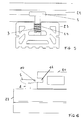
figure 1 représente une vue en position éclatée d'un ensemble comprenant une lambourde, une lame et un dispositif de fixation ; - La
figure 2 représente une vue en perspective d'un dispositif de fixation conforme à l'invention ; - La
figure 3 représente une vue en perspective d'un dispositif de fixation vu sous un autre angle ; - La
figure 4 représente une vue en perspective d'un dispositif de fixation conforme à l'invention prise côté bras du dispositif ; - Les
figures 5 à 10 représentent, de manière schématique, les différentes étapes de pose d'un dispositif de fixation à un profilé support, lesfigures 5 ,7 et9 correspondant à des vues en coupe transversale de la lambourde et de face de la lame, lesfigures 6 ,8 et10 correspondant à des vues en coupe transversale de la lame et de face de la lambourde ; - La
figure 11 représente une vue schématique d'un dispositif de fixation avec une vue de détail du filetage pour permettre une visualisation des méplats.
- The
figure 1 represents an exploded view of an assembly comprising a joists, a blade and a fixing device; - The
figure 2 represents a perspective view of a fastening device according to the invention; - The
figure 3 represents a perspective view of a fastening device viewed from another angle; - The
figure 4 represents a perspective view of a fastening device according to the invention taken on the arm side of the device; - The
Figures 5 to 10 represent, in a schematic manner, the various steps of laying a fastening device to a support profile, thefigures 5 ,7 and9 corresponding to cross-sectional views of the jib and face of the blade, thefigures 6 ,8 and10 corresponding to cross-sectional views of the blade and face of the joist; - The
figure 11 is a schematic view of a fastener with a detailed view of the thread to allow viewing of the flats.
Comme mentionné ci-dessus, le dispositif 1, objet de l'invention, est plus particulièrement destiné à la fixation de lames 20 de parement, par exemple des lames 20 de terrasse, à un profilé support 23, tel qu'une lambourde en bois.As mentioned above, the
Généralement les profilés support 23 sont disposés parallèles entre eux pour former un réseau de profilés support 23. Ces profilés support 23 permettent d'absorber les éventuelles irrégularités du sol, évitent de fixer les lames dans le sol au risque de l'endommager, ou offrent une fixation qu'un sol trop meuble ne permet pas toujours, et ménagent un espace entre les lames et le sol pour l'écoulement des eaux de pluies.Generally, the
Les lames 20 sont disposées perpendiculairement auxdits profilés support 23 et sont destinées à être supportées par ces derniers. Une même lame est supportée par plusieurs profilés support et est fixée à au moins certains de ces derniers par un dispositif de fixation. Un dispositif de fixation assujettit donc au moins une, généralement deux lames disposées côte à côte à un profilé support 23.The
Chaque lame 2 de plancher est de section sensiblement rectangulaire. Elle comporte une surface d'appui sur les lambourdes, une surface pour marcher dessus, deux bords longitudinaux et des extrémités définissant la longueur utile de la lame.Each
Deux lames adjacentes comprennent respectivement des bords longitudinaux en vis-à-vis. Ces bords sont disposés sensiblement parallèles principalement pour des raisons esthétiques. Ces bords sont distants d'une distance sensiblement constante.Two adjacent blades respectively comprise longitudinal edges vis-à-vis. These edges are arranged substantially parallel mainly for aesthetic reasons. These edges are distant by a substantially constant distance.
Dans le cas d'une terrasse extérieure, cette distance entre les bords permet l'écoulement des eaux de pluie entre les lames puis sous les lames de plancher.In the case of an outdoor terrace, this distance between the edges allows the flow of rainwater between the blades and then under the floorboards.
Outre, les caractéristiques géométriques déjà citées, les lames 20 comprennent aussi dans leurs bords longitudinaux ou chant 21 des rainures 22. Ces rainures se prolongent sur toute la longueur de chacun des chants d'une lame. Elles ont une section rectangulaire de hauteur, de profondeur et d'élévation depuis la surface d'une lame sensiblement constantes pour toutes les lames.In addition to the geometric characteristics already mentioned, the
Chaque profilé support 23 comporte, quant à lui, une face du dessous d'appui au sol et une face du dessus opposée munie d'une gorge longitudinale dont les flancs sont équipés chacun d'une aile 24 longitudinale, dite en retour, c'est-à-dire orientée en direction de l'intérieur de la gorge et qui ferme partiellement l'ouverture de ladite gorge.Each
La gorge avec ses ailes 24 en retour présente une section transversale en forme de T inversé en position d'appui du profilé support 23 reposant sur le sol par sa face inférieure.The groove with its
Le dispositif de fixation est une pièce monobloc, de préférence monolithique, réalisée de préférence en métal ou en alliage métallique. A titre d'exemple, le dispositif de fixation est en un alliage de zinc, d'aluminium et de magnésium encore appelé zamac.The fixing device is a one-piece piece, preferably monolithic, preferably made of metal or metal alloy. By way of example, the fixing device is made of an alloy of zinc, aluminum and magnesium, also called zamac.
Le dispositif de fixation comprend une tige 2 cylindrique filetée sur une partie de sa longueur. Le filetage est un filetage hélicoïdal qui se développe avec un pas à droite. Le filetage 3 de la tige 2 est interrompu dans deux plans sensiblement parallèles à la direction des bras 11. Ces plans tangentent le corps de la tige. L'interruption du filetage 3 forme donc sur la tige 2 deux méplats 4 diamétralement opposés.The fixing device comprises a
Cette tige 2 présente un diamètre sensiblement égal à la distance souhaitée entre deux lames 20 adjacentes. Cette tige 2 est munie à l'une de ses extrémités d'une tête 5 de forme générale cylindrique, de hauteur inférieure au diamètre. Cette tête 5 est destinée à s'insérer dans une rainure 22 de la lame 20 à assujettir au profilé support 23.This
La face 6 supérieure de la tête est une face circulaire sensiblement plane munie d'un logement 7 de réception d'un outil d'entraînement en rotation du dispositif. Le logement 7 est ici formé d'une cavité hexagonale apte à recevoir une clé alène.The upper face 6 of the head is a substantially flat circular face provided with a
La face inférieure 8 présente une zone 9 diamétrale épaisse et, symétriquement par rapport à ladite zone 9 diamétrale épaisse, deux zones 10 d'amincissement vers la périphérie. Chaque zone 10 d'amincissement forme au moins une rampe inclinée apte à coopérer avec la rainure 22 de la lame 20 lors de la rotation du dispositif.The
Dans les exemples représentés, la face 8 inférieure de la tête 5 est munie de deux pans coupés disposés de manière symétrique l'un, d'un côté, l'autre, de l'autre côté, d'un plan diamétral de la tête formant la zone 9 diamétrale épaisse de la tête. Lesdits pans coupés délimitent chacun une surface inclinée prenant naissance sur la face inférieure le long d'une ligne parallèle au plan diamétral et se développant en direction du bord périphérique de la tête dans le sens d'un amincissement de ladite tête pour former chacun l'une des zones 10 d'amincissement de ladite tête.In the examples shown, the
Dans les exemples représentés, chaque zone 10 d'amincissement présente un plan de symétrie perpendiculaire à la zone 9 diamétrale épaisse.In the examples shown, each thinning
Chaque zone d'amincissement permet ainsi une rotation à droite ou à gauche du dispositif. Cette zone d'amincissement facilite la pénétration de la tête 5 dans la rainure 22 de la lame puis assure, grâce au profil de came de la face inférieure, le serrage de la lame sur le profilé support lors de l'entraînement en rotation du dispositif comme cela décrit ci-après.Each thinning zone thus allows a rotation to the right or left of the device. This thinning zone facilitates the penetration of the
La tige 2 est munie à son extrémité opposée de deux bras 11. Ces bras 11 sont disposés à un même niveau de la tige dans le prolongement l'un de l'autre. Les bras et la tige forment sensiblement un T inversé en position dressée de la tige avec les bras disposés à l'extrémité inférieure de la tige. Ces bras sont donc sensiblement symétriques par rapport à la tige, ladite symétrie étant une symétrie axiale.The
Ces bras s'étendent sensiblement perpendiculairement à la zone 9 diamétrale épaisse. Ces bras sont d'épaisseur au plus égale à la distance séparant le fond de la gorge de l'aile en retour de ladite gorge du profilé support et sont de longueur légèrement supérieure à la largeur de la gorge du profilé support.These arms extend substantially perpendicular to the thick
Ces bras 11 comportent ici un bord longitudinal qui s'étend sensiblement perpendiculairement à la zone 9 diamétrale épaisse et un bord longitudinal qui tend, au cours de son développement depuis la tige en direction de l'extrémité libre du bras, à se rapprocher de l'autre bord. Les extrémités 12 des bras 11 sont des extrémités droites parallèles entre elles et sensiblement parallèles à la zone 9 diamétrale épaisse.These
Cette extrémité droite permet ainsi un appui face sur face avec l'intérieur du profilé support, l'extrémité de chaque bras venant en appui contre un flanc de la gorge du profilé support en position de fixation des bras dans le profilé support.This right end thus allows a face-to-face support with the inside of the support profile, the end of each arm bearing against a side of the groove of the support profile in the position of attachment of the arms in the support profile.
La face inférieure de la tête et sur la face en regard des bras sont écartées l'une de l'autre d'une distance supérieure à la somme de l'épaisseur de l'aile en retour du profilé support et de la distance séparant la rainure de la face inférieure d'appui sur le profilé support de la lame.The lower face of the head and the opposite side of the arms are spaced from each other by a distance greater than the sum of the thickness of the wing in return of the support profile and the distance separating the groove of the underside of support on the support section of the blade.
Les bras 11 sont aptes à occuper, dans le profilé support, une première position de démontage dans laquelle lesdits bras 11 sont sensiblement parallèles aux bords longitudinaux du profilé support 23, et une deuxième position de fixation dans laquelle lesdits bras 11 sont engagés sous les ailes 24 du profilé support 23. Le passage d'une position à une autre est obtenu par rotation du dispositif.The
En pratique, la fixation s'opère comme suit, comment l'illustrent les
On suppose que les profilés support parallèles entre eux sont fixés au sol, qu'une première lame, positionnée perpendiculairement au profilé support, est également fixée audit profilé support par exemple par vissage ou autre. Les autres lames, à l'exception généralement de la dernière lame de la terrasse à réaliser peuvent alors être fixées au profilé support à l'aide du dispositif de fixation du type de celui décrit ci-dessus.It is assumed that the parallel support profiles are fixed to the ground, that a first blade, positioned perpendicularly to the support profile, is also fixed to said support profile for example by screwing or other. The other blades, with the exception of generally the last plate of the terrace to be made can then be attached to the support profile using the fixing device of the type described above.
On commence par insérer les dispositifs de fixation dans le profilé support 23. Les bras du dispositif de fixation sont donc positionnés sensiblement parallèlement aux bords longitudinaux du profilé support et introduits axialement dans l'espace laissé libre entre les deux ailes en retour jusqu'à venir reposer au fond de la gorge du profilé support 23.The fasteners are first inserted into the
Le dispositif de fixation est amené par coulissement ou déplacement axial à l'intérieur de la gorge jusqu'au contact de la lame de sorte que la tête du dispositif est introduite par sa zone d'amincissement dans une rainure de la lame.The fixing device is slidably or axially moved inside the groove until the blade is in contact with the end of the device so that the head of the device is introduced through its groove area into a groove of the blade.
On note, en effet, que chaque zone d'amincissement est disposée au-dessus d'une partie filetée de la tige et au-dessus d'un bras à l'état dressé de la tige avec la tête disposée au-dessus des bras.It is noted, in fact, that each thinning zone is disposed above a threaded portion of the rod and above an arm in the erect state of the rod with the head disposed above the arms .
La faible épaisseur de la tête facilite l'introduction de la tête dans la rainure. La surface inclinée formée par cet amincissement permet de faire remonter le dispositif et d'écarter les bras du fond de la gorge du profilé support.The small thickness of the head facilitates the introduction of the head into the groove. The inclined surface formed by this thinning makes it possible to raise the device and to separate the arms from the bottom of the groove of the support profile.
Dans cette position où la tête est introduite dans la rainure de la lame, dite première lame, il est possible de rapprocher une deuxième lame parallèle à la première lame de ladite première lame jusqu'à introduction de la deuxième zone d'amincissement de la tête dans la rainure de la deuxième lame.In this position where the head is introduced into the groove of the blade, said first blade, it is possible to bring a second blade parallel to the first blade of said first blade until introduction of the second zone of thinning of the head in the groove of the second blade.
Le dispositif est ensuite entraîné en rotation à l'aide de la clé alène introduite dans le logement 7 hexagonal de la face 8 supérieure de la tête. La course angulaire est inférieure à un quart de tour pour éviter une détérioration du profilé support.The device is then rotated with the aid of the key introduced in the
Parallèlement au vissage de la tige dans les ailes en retour du profilé support, la tête applique la lame sur le profilé support grâce à la rampe inclinée formée par la face inférieure de ladite lame.Parallel to the screwing of the rod in the wings back of the support profile, the head applies the blade on the support profile through the inclined ramp formed by the underside of said blade.
Le montage est achevé. Cette opération est répétée pour chaque dispositif de fixation qui a été associé à un profilé support destiné à être assujetti auxdites première et deuxième lames.The editing is complete. This operation is repeated for each fixing device which has been associated with a support profile intended to be secured to said first and second blades.
Les opérations décrites ci-dessus peuvent être répétées pour l'assemblage d'une nouvelle lame.The operations described above can be repeated for assembling a new blade.
Claims (9)
caractérisé en ce que la tige (2) est filetée et en ce que ladite tête (5) est de forme générale cylindrique, de hauteur inférieure au diamètre, avec une face (6) dite supérieure, de préférence sensiblement plane, munie d'un logement (7) de réception d'un outil d'entrainement en rotation du dispositif et une face (8) inférieure présentant, symétriquement par rapport à une zone (9) diamétrale épaisse, deux zones (10) d'amincissement vers la périphérie, chaque zone (10) d'amincissement formant au moins une rampe inclinée apte à coopérer avec ladite rainure (22) de la lame (20) lors de la rotation du dispositif de la position de démontage à la position de fixation.Device for fastening a grooved edge blade (20) (21) grooved to a support profile (23), such as a joists, having two longitudinal wings (24) in return facing towards the inside of the profile , to maintain the blade (20) transverse to the support profile (23), applies to said support profile (23), said device comprising a rod (2) provided at one of its ends with a head ( 5) adapted to partially fit into a groove (22) of the blade (20), and at or near the other end, two arms (11) substantially symmetrical relative to the rod (2) fit in the support profile (23) occupying a first disassembling position in which said arms (11) are substantially parallel to the longitudinal edges of the support profile (23), and a second fixing position in which said arms (11) are engaged under the wings (24) of the support profile (23),
characterized in that the rod (2) is threaded and in that said head (5) is of generally cylindrical shape, of height less than the diameter, with a face (6) said upper, preferably substantially flat, provided with a housing (7) for receiving a tool for rotating the device and a lower face (8) having, symmetrically with respect to a thick diametrical zone (9), two zones (10) of thinning towards the periphery, each zone (10) of thinning forming at least one inclined ramp capable of cooperating with said groove (22) of the blade (20) during the rotation of the device from the disassembly position to the fixing position.
caractérisé en ce que la zone (9) diamétrale épaisse est sensiblement perpendiculaire auxdits bras (11).Device according to claim 1,
characterized in that the thick diametric zone (9) is substantially perpendicular to said arms (11).
caractérisé en ce que le filetage (3) de la tige (2) est interrompu dans deux plans sensiblement parallèles à la direction des bras (11), l'interruption du filetage (3) formant sur la tige (2) deux méplats (4) diamétralement opposés.Device according to one of claims 1 or 2,
characterized in that the thread (3) of the rod (2) is interrupted in two planes substantially parallel to the direction of the arms (11), the interruption of the thread (3) forming on the rod (2) two flats (4) diametrically opposed.
caractérisé en ce que chaque zone (10) d'amincissement présente un plan de symétrie perpendiculaire à la zone (9) diamétrale épaisse.Device according to one of claims 1 to 3,
characterized in that each zone (10) of thinning has a plane of symmetry perpendicular to the zone (9) diametric thick.
caractérisé en ce que chaque bras (11) présente une extrémité (12) à bout droit s'étendant sensiblement parallèlement à la zone (9) diamétrale épaisse.Device according to one of claims 1 to 4,
characterized in that each arm (11) has a straight end (12) extending substantially parallel to the thick diametric zone (9).
caractérisé en ce que ledit dispositif de fixation est conforme à l'une des revendications 1 à 5.Assembly of the type formed by at least one grooved edge facing blade (10), a fastening device (1) and a support profile (23) of said blade (20) secured to said support profile (23) by said device (1),
characterized in that said fixing device is according to one of claims 1 to 5.
caractérisé en ce qu'il comporte, associées à une même lame (20) de parement une pluralité de profilés support (23) et de dispositifs (1) de fixation, lesdits profilés support (23), de préférence en bois, étant disposés parallèles pour former un réseau de profilés support de la lame (10) positionnée orthogonalement auxdits profilés (23) à l'état assujetti, les extrémités (12) des bras (11) de chaque dispositif de fixation étant positionnées sous les ailes (24) d'un profilé support (23) auquel le dispositif (1) de fixation est associé.Assembly according to Claim 6,
characterized in that it comprises, associated with the same blade (20) facing a plurality of support profiles (23) and devices (1) for fixing, said support profiles (23), preferably wooden, being arranged parallel to form a network of support profiles of the blade (10) positioned orthogonally to said profiles (23) in the fastened state, the ends (12) of the arms (11) of each fixing device being positioned under the wings (24) of a support profile (23) to which the fixing device (1) is associated.
caractérisé en ce que ledit procédé comprend au moins une étape d'introduction, à l'intérieur du profilé support (23) des bras (11) du dispositif (1) de fixation positionnés sensiblement parallèlement aux bords longitudinaux du profilé support (23), une étape de déplacement axial du dispositif (1) de fixation à l'intérieur du profilé support (23) jusqu'à introduction partielle de la tête (5) du dispositif de fixation dans une rainure (22) d'une lame (20), dite première lame, de parement et une étape de rotation d'au plus un quart de tour du dispositif pour amener les extrémités (12) des bras sous les ailes (24) du profilé support (23) parallèlement au vissage du dispositif dans le profilé support (23).Method for fastening at least one blade (20) to a support profile (23) by means of a fastening device (1) according to one of Claims 1 to 5 for the production of a assembly according to one of claims 6 or 7,
characterized in that said method comprises at least one step introducing, inside the support profile (23), the arms (11) of the fixing device (1) positioned substantially parallel to the longitudinal edges of the support profile (23), a step of axial displacement of the device (1) of fixing inside the support profile (23) until the head (5) of the fastener is partially inserted into a groove (22) of a blade (20), said first blade, facing and a step of rotation of not more than a quarter turn of the device to bring the ends (12) of the arms under the wings (24) of the support profile (23) parallel to the screwing of the device in the support profile (23).
caractérisé en ce qu'il comprend en outre, préalablement à l'étape de rotation du dispositif, une étape de rapprochement d'une deuxième lame de parement de la première lame jusqu'à insertion de la tête du dispositif dans la rainure (22) de ladite deuxième lame (20).Process according to claim 8,
characterized in that it further comprises, prior to the step of rotation of the device, a step of approaching a second facing blade of the first blade until insertion of the head of the device into the groove (22) said second blade (20).
Applications Claiming Priority (1)
| Application Number | Priority Date | Filing Date | Title |
|---|---|---|---|
| FR1254418A FR2990713B1 (en) | 2012-05-15 | 2012-05-15 | METHOD AND DEVICE FOR FASTENING A SINGLE-EDGE BLADE GROOVED TO A SUPPORT PROFILE, AND ASSEMBLY FORMED OF AT LEAST ONE FIXING DEVICE OF THE ABOVE TYPE |
Publications (1)
| Publication Number | Publication Date |
|---|---|
| EP2664731A1 true EP2664731A1 (en) | 2013-11-20 |
Family
ID=46852127
Family Applications (1)
| Application Number | Title | Priority Date | Filing Date |
|---|---|---|---|
| EP13160412.6A Withdrawn EP2664731A1 (en) | 2012-05-15 | 2013-03-21 | Method and device for attaching a grooved-edge facing strip to a supporting profile and assembly made up of at least one attachment device of the aforementioned type |
Country Status (2)
| Country | Link |
|---|---|
| EP (1) | EP2664731A1 (en) |
| FR (1) | FR2990713B1 (en) |
Cited By (8)
| Publication number | Priority date | Publication date | Assignee | Title |
|---|---|---|---|---|
| CN103934868A (en) * | 2014-05-02 | 2014-07-23 | 彭志军 | Log spliced board structure |
| DE202013010369U1 (en) * | 2013-11-19 | 2015-02-20 | Hans Dieter Grotefeld | Mounting element for planks, tiles or the like |
| WO2015159136A1 (en) * | 2014-04-16 | 2015-10-22 | Control Y Desarrollo Empresarial, S.L. | Covering comprising cover plates clamped to profiles |
| WO2016083497A1 (en) * | 2014-11-26 | 2016-06-02 | Nmc Sa | Lockable connection means |
| BE1022940B1 (en) * | 2014-11-26 | 2016-10-20 | Nmc Sa | Lockable connecting means |
| DE102015010894A1 (en) * | 2015-08-19 | 2017-02-23 | Markus Rensburg | Mounting kit for the terrace construction |
| US10526796B1 (en) * | 2017-06-26 | 2020-01-07 | Crescent Equipment Company | Deck systems and related methods |
| GB2582618A (en) * | 2019-03-28 | 2020-09-30 | Ryno Ltd | A decking assembly and decking support assembly |
Citations (5)
| Publication number | Priority date | Publication date | Assignee | Title |
|---|---|---|---|---|
| FR2818677A1 (en) | 2000-12-22 | 2002-06-28 | Grp D Exportation Et De Diffus | Fastener e.g. for grooved decking boards has central cylinder for board edges to fit against and radial arms to engage with grooves |
| EP1600579A1 (en) | 2004-02-27 | 2005-11-30 | Cerland S.A.S. | Fastening system for cladding boards, in particular parquet floorboards |
| FR2901565A1 (en) | 2006-05-24 | 2007-11-30 | Andre Quinquenel | Face strip e.g. floor strip, and support profile e.g. sleeper, fixing device, has bars respectively inserted into groove of face strip and support profile to maintain face strip against support profile by applying elastic effect of device |
| EP2275613A2 (en) * | 2009-07-16 | 2011-01-19 | Pinufin Oberflächentechnik GmbH & Co. KG | Cladding composed of profile elements |
| WO2011149371A1 (en) | 2010-05-27 | 2011-12-01 | Iht, Lda. | Profile fixing accessory and system for fixing profiles using said accessory |
-
2012
- 2012-05-15 FR FR1254418A patent/FR2990713B1/en active Active
-
2013
- 2013-03-21 EP EP13160412.6A patent/EP2664731A1/en not_active Withdrawn
Patent Citations (5)
| Publication number | Priority date | Publication date | Assignee | Title |
|---|---|---|---|---|
| FR2818677A1 (en) | 2000-12-22 | 2002-06-28 | Grp D Exportation Et De Diffus | Fastener e.g. for grooved decking boards has central cylinder for board edges to fit against and radial arms to engage with grooves |
| EP1600579A1 (en) | 2004-02-27 | 2005-11-30 | Cerland S.A.S. | Fastening system for cladding boards, in particular parquet floorboards |
| FR2901565A1 (en) | 2006-05-24 | 2007-11-30 | Andre Quinquenel | Face strip e.g. floor strip, and support profile e.g. sleeper, fixing device, has bars respectively inserted into groove of face strip and support profile to maintain face strip against support profile by applying elastic effect of device |
| EP2275613A2 (en) * | 2009-07-16 | 2011-01-19 | Pinufin Oberflächentechnik GmbH & Co. KG | Cladding composed of profile elements |
| WO2011149371A1 (en) | 2010-05-27 | 2011-12-01 | Iht, Lda. | Profile fixing accessory and system for fixing profiles using said accessory |
Cited By (11)
| Publication number | Priority date | Publication date | Assignee | Title |
|---|---|---|---|---|
| DE202013010369U1 (en) * | 2013-11-19 | 2015-02-20 | Hans Dieter Grotefeld | Mounting element for planks, tiles or the like |
| WO2015159136A1 (en) * | 2014-04-16 | 2015-10-22 | Control Y Desarrollo Empresarial, S.L. | Covering comprising cover plates clamped to profiles |
| CN106232915A (en) * | 2014-04-16 | 2016-12-14 | 控制与发展企业有限公司 | Overcover including the covering plate being clamped to section bar |
| CN103934868A (en) * | 2014-05-02 | 2014-07-23 | 彭志军 | Log spliced board structure |
| WO2016083497A1 (en) * | 2014-11-26 | 2016-06-02 | Nmc Sa | Lockable connection means |
| BE1022940B1 (en) * | 2014-11-26 | 2016-10-20 | Nmc Sa | Lockable connecting means |
| DE102015010894A1 (en) * | 2015-08-19 | 2017-02-23 | Markus Rensburg | Mounting kit for the terrace construction |
| DE102015010894B4 (en) * | 2015-08-19 | 2018-10-25 | Markus Rensburg | Mounting kit for the terrace construction |
| US10526796B1 (en) * | 2017-06-26 | 2020-01-07 | Crescent Equipment Company | Deck systems and related methods |
| GB2582618A (en) * | 2019-03-28 | 2020-09-30 | Ryno Ltd | A decking assembly and decking support assembly |
| GB2582618B (en) * | 2019-03-28 | 2021-04-14 | Ryno Ltd | A decking assembly and decking support assembly |
Also Published As
| Publication number | Publication date |
|---|---|
| FR2990713B1 (en) | 2014-06-06 |
| FR2990713A1 (en) | 2013-11-22 |
Similar Documents
| Publication | Publication Date | Title |
|---|---|---|
| EP2664731A1 (en) | Method and device for attaching a grooved-edge facing strip to a supporting profile and assembly made up of at least one attachment device of the aforementioned type | |
| EP3126590B1 (en) | Device for attaching covering elements to a floor batten | |
| CA2628810C (en) | Method for mounting blades on a supporting structure and improved fixing element | |
| FR3039576A1 (en) | FORMING HOLDING DEVICE FOR BUILDING ELEMENT, BUILDING ELEMENT PROVIDED WITH SAID DEVICE AND FORMWORKING METHOD USING SAID DEVICE | |
| FR2519072A1 (en) | DEVICE FOR AXIAL AND RADIAL RETENTION OF A TURBO JET ROTOR BLADE | |
| EP2636815A2 (en) | U-bolt for attaching a handrail top rail to a post | |
| EP2795141B1 (en) | System enabling the attachment of an object to an element having attachment groove(s), and attachment device for such a system | |
| EP2159344B1 (en) | Calliper for fixing a bar to an upright | |
| FR3049301A1 (en) | CLAMPER SYSTEM AND DEVICE FOR FASTENING A CARPENTRY DORMANT | |
| FR2997740A1 (en) | DEVICE FOR ATTACHING AN ATTACHMENT TO AN ORIENTED ROOF. | |
| CA2194871A1 (en) | Adjustable staircase | |
| FR2922237A1 (en) | Fastener for suspending panel of suspended ceiling to ceiling wall, has plate hooked in suspension to lower free flange of I-shaped beam for anchoring board in metallic suspension section so that section is maintained in suspension at beam | |
| FR2766905A1 (en) | Folded section girder for building construction | |
| EP2163703A1 (en) | Variably angled connection device between two hollow profiles | |
| EP2360381B1 (en) | Connection element for threshold strips | |
| EP3751158B1 (en) | Concrete screw for hanging a framework for a suspended ceiling | |
| FR2818677A1 (en) | Fastener e.g. for grooved decking boards has central cylinder for board edges to fit against and radial arms to engage with grooves | |
| FR3048709A1 (en) | FIXING DEVICE FOR CEILING OSSATURE | |
| FR2766904A1 (en) | C- sectional steel girder for building | |
| EP3870866A1 (en) | Rotary attachment accessory | |
| EP3835510B1 (en) | Handrail device for a railing | |
| FR3026120B1 (en) | BUTTERFLY TYPE INSTALLATION DEVICE | |
| EP3059714B1 (en) | Consignment device for tubular handle of nestable cart | |
| FR3007087A1 (en) | FASTENING CLIP AND ASSEMBLY HAVING FASTENING CLIP | |
| FR2702808A1 (en) | Improvements to devices for fastening objects onto sheets which are accessible from just one side |
Legal Events
| Date | Code | Title | Description |
|---|---|---|---|
| PUAI | Public reference made under article 153(3) epc to a published international application that has entered the european phase |
Free format text: ORIGINAL CODE: 0009012 |
|
| AK | Designated contracting states |
Kind code of ref document: A1 Designated state(s): AL AT BE BG CH CY CZ DE DK EE ES FI FR GB GR HR HU IE IS IT LI LT LU LV MC MK MT NL NO PL PT RO RS SE SI SK SM TR |
|
| AX | Request for extension of the european patent |
Extension state: BA ME |
|
| STAA | Information on the status of an ep patent application or granted ep patent |
Free format text: STATUS: THE APPLICATION IS DEEMED TO BE WITHDRAWN |
|
| 18D | Application deemed to be withdrawn |
Effective date: 20140521 |