EP2664252B1 - Höhenverstellbares Möbel - Google Patents
Höhenverstellbares Möbel Download PDFInfo
- Publication number
- EP2664252B1 EP2664252B1 EP13159670.2A EP13159670A EP2664252B1 EP 2664252 B1 EP2664252 B1 EP 2664252B1 EP 13159670 A EP13159670 A EP 13159670A EP 2664252 B1 EP2664252 B1 EP 2664252B1
- Authority
- EP
- European Patent Office
- Prior art keywords
- height
- lifting
- furniture body
- furniture
- adjustable
- Prior art date
- Legal status (The legal status is an assumption and is not a legal conclusion. Google has not performed a legal analysis and makes no representation as to the accuracy of the status listed.)
- Active
Links
- 230000001360 synchronised effect Effects 0.000 claims description 5
- 238000010276 construction Methods 0.000 description 2
- 101100390736 Danio rerio fign gene Proteins 0.000 description 1
- 101100390738 Mus musculus Fign gene Proteins 0.000 description 1
- 238000010411 cooking Methods 0.000 description 1
- 238000009434 installation Methods 0.000 description 1
- 238000000034 method Methods 0.000 description 1
- 230000003287 optical effect Effects 0.000 description 1
- 239000007787 solid Substances 0.000 description 1
Images


Classifications
-
- A—HUMAN NECESSITIES
- A47—FURNITURE; DOMESTIC ARTICLES OR APPLIANCES; COFFEE MILLS; SPICE MILLS; SUCTION CLEANERS IN GENERAL
- A47B—TABLES; DESKS; OFFICE FURNITURE; CABINETS; DRAWERS; GENERAL DETAILS OF FURNITURE
- A47B51/00—Cabinets with means for moving compartments up and down
-
- A—HUMAN NECESSITIES
- A47—FURNITURE; DOMESTIC ARTICLES OR APPLIANCES; COFFEE MILLS; SPICE MILLS; SUCTION CLEANERS IN GENERAL
- A47B—TABLES; DESKS; OFFICE FURNITURE; CABINETS; DRAWERS; GENERAL DETAILS OF FURNITURE
- A47B77/00—Kitchen cabinets
- A47B77/04—Provision for particular uses of compartments or other parts ; Compartments moving up and down, revolving parts
-
- A—HUMAN NECESSITIES
- A47—FURNITURE; DOMESTIC ARTICLES OR APPLIANCES; COFFEE MILLS; SPICE MILLS; SUCTION CLEANERS IN GENERAL
- A47B—TABLES; DESKS; OFFICE FURNITURE; CABINETS; DRAWERS; GENERAL DETAILS OF FURNITURE
- A47B9/00—Tables with tops of variable height
- A47B9/20—Telescopic guides
Definitions
- the invention relates to a height-adjustable furniture, in particular cupboards or kitchen countertop, with two mountable on a fixed wall lifting columns on the vertically movable lifting heads a furniture body is attached, inside the furniture body two mounting hardware are mounted with which the furniture body from the top of the lifting heads form-fitting is plugged.
- Such a height-adjustable furniture is, for example, by the NL 1 007 024 C2 known.
- the height-adjustable furniture body e.g. a base cabinet, screwed to the lifting columns or lifting units, which means a high installation cost.
- NL 1 007 024 C2 is a cabinet furniture with two mountable on a fixed wall lifting columns known, on the vertically movable lifting struts a wall unit is attached. Two mounting fittings are mounted on the cabinet body, with which the cabinet carcass is positively attached from above to the lifting struts.
- the height adjustment has two mountable on a fixed wall lifting columns, in each of which a runner is guided vertically displaceable.
- the two runners are connected to each other via a cross member to which the wall unit is attached.
- the height adjustment takes place via a spindle drive, which engages on the one hand on the cross member of the two runners and on the other hand on a cross member of the two lifting columns.
- At least one intermediate cross member is attached to the two lifting heads, on which in turn a lifting unit is supported for a height adjustable relative to the furniture body, in particular retractable into the furniture body means.
- the height-adjustable device can be a lifting shelf which can be lowered into the furniture body or a retractable extractor hood.
- the two mounting fittings are preassembled in the two rear, upper carcass corners of the furniture body, whereby the stability of the carcass construction is increased.
- the small depth of the mounting hardware allows 100% use of space within the furniture body, such. for drawers.
- Between the two mounting brackets and the furniture body is advantageous in each case an adjusting device for adjusting the furniture body with respect. Inclination, height, side and depth available.
- the lifting columns have one or more, in particular tool-free retrofitted gas springs to compensate for the weight of the furniture body and possibly further attached to the furniture body elements.
- the two lifting columns are synchronized with each other electronically for synchronous operation of their lifting heads, so that the gap between the two lifting columns can be used elsewhere.
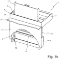
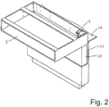
- height-adjustable furniture 1 has a height-adjustable furniture body 2 , which serves as a base of a kitchen worktop (not shown) in the illustrated embodiment.
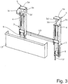
- the furniture 1 further comprises two mounted on a fixed wall lifting units or lifting columns 3 , each with upwardly extendable lifting heads 4 , where the furniture body 2 is attached. These are inside the two rear, upper carcass corners on furniture body 2 pre-assembled two mounting fittings 5 , which are each formed as a back and one side closed mounting bracket with a horizontal bottom plate 5a and with each angled down front, rear and side walls 5b-5d ,
- the mounting fittings 5 are open on the sides facing each other.
- the mounting hardware 5 could be open on the opposite sides or be closed all around.
- the furniture body 2 is plugged with its two pre-assembled mounting hardware 5 without tools from above the lifting heads 4, whereby the bottom plates 5a rest on top of the lifting heads 4 and the three downwardly angled walls 5b-5d include the lifting heads 4 positively.
- the mounting hardware 5 are positively placed and thus accurately fit on the lifting heads 4.
- the attacks are 5 b, 5 c side and rear of the lifting heads 4, to guide the furniture body 2 laterally and in depth when plugging.
- the plugged mounting fittings 5 are secured to the lifting heads 4.
- the mounting fittings 5 also increase the stability of the entire furniture body. 2
- the lifting columns 3 are designed as electric linear drives, which are each integrated in a stable heavy duty roller guide.
- the drive motor is completely hidden inside the lifting column 3.
- the two lifting columns 3 are synchronized with each other electronically. Since the worktop and the furniture body 2 together can weigh more than 100kg, one, in particular, tool-free retrofit gas spring 8 is installed in the lifting columns 3, which should compensate for the weight of the worktop and the furniture body 2.
- an adjusting device 9 not shown in detail (FIG. Fig. 1 b) arranged to adjust the furniture body 2 respect. Its inclination, height, side and depth relative to the mounting fittings 5 can.
- the two lifting columns 3 by means of a horizontal wall rail 10 to any solid wall, a room wall or a furniture wall 11 (FIG. FIGS. 1 and 2 ) can be fixed and can With respect to their side, depth and tilt relative to the Wandschiebne 10 are adjusted.
- the lifting columns 3 can be additionally supported on the ground.
- a cover plate 13 is fixed, which mitvertex with the furniture body 2 and the optical panel of the lifting columns 3 is used.
- the closed back 2a of the furniture body 2 has a high quality surface finish, since this back 2a in the in Fig.
- a transverse cross member 15 extending therebetween is attached to the two lifting heads 4, which mitvertex with the lifting heads 4.
- a lifting unit or column 16 is supported, for example, a lifting rack 17 ( FIG. Fig. 1 b) or to raise an extractor hood (not shown) from the furniture body 2 and sink it.
Landscapes
- Combinations Of Kitchen Furniture (AREA)
Description
- Die Erfindung betrifft ein höhenverstellbares Möbel, insbesondere Schrankmöbel oder Küchenarbeitsplatte, mit zwei an einer festen Wand montierbaren Hubsäulen, an deren vertikal verfahrbaren Hubköpfen ein Möbelkorpus befestigt ist, wobei innen am Möbelkorpus zwei Montagebeschläge montiert sind, mit denen der Möbelkorpus von oben auf die Hubköpfe formschlüssig aufgesteckt ist.
- Ein derartiges höhenverstellbares Möbel ist beispielsweise durch die
NL 1 007 024 C2 - Bei bekannten höhenverstellbaren Möbeln ist der höhenverfahrbare Möbelkorpus, z.B. ein Unterschrank, an den Hubsäulen bzw. Hubeinheiten angeschraubt, was einen hohen Montageaufwand bedeutet.
- Aus der eingangs genannten
NL 1 007 024 C2 - Aus der
EP 0 402 283 A ist weiterhin eine Höhenverstellung für einen Hängeschrank bekannt. Die Höhenverstellung weist zwei an einer festen Wand montierbare Hubsäulen bekannt, in denen jeweils ein Läufer vertikal verschiebbar geführt ist. Die beiden Läufer sind über einen Querträger miteinander verbunden, an dem der Hängeschrank befestigt wird. Die Höhenverstellung erfolgt über einen Spindelantrieb, der einerseits an dem Querträger der beiden Läufer und andererseits an einem Querträger der beiden Hubsäulen angreift. - Um die Vielseitigkeit des Möbelkorpus zu erhöhen, ist erfindungsgemäß an den beiden Hubköpfen mindestens eine dazwischen verlaufende Quertraverse befestigt, an der wiederum eine Hubeinheit für eine relativ zum Möbelkorpus höhenverfahrbare, insbesondere bis in den Möbelkorpus versenkbare Einrichtung abgestützt ist. Beispielsweise kann es sich bei der höhenverfahrbaren Einrichtung um ein im Möbelkorpus versenkbares Hubregal oder eine versenkbare Dunstabzugshaube handeln.
- Vorzugsweise sind die beiden Montagebeschläge in den beiden hinteren, oberen Korpusecken des Möbelkorpus vormontiert, wodurch auch die Stabilität der Korpuskonstruktion erhöht wird. Die geringe Bautiefe der Montagebeschläge ermöglicht eine 100%ige Raumnutzung innerhalb des Möbelkorpus, wie z.B. für Schubladen. Zwischen den beiden Montagebeschlägen und dem Möbelkorpus ist vorteilhaft jeweils eine Justiervorrichtung zum Justieren des Möbelkorpus bzgl. Neigung, Höhe, Seite und Tiefe vorhanden.
- Vorzugsweise weisen die Hubsäulen eine oder mehrere, insbesondere werkzeuglos nachrüstbare Gasfedern auf, um das Eigengewicht des Möbelkorpus und ggf. weiterer am Möbelkorpus befestigter Elemente zu kompensieren.
- Bevorzugt sind die beiden Hubsäulen für ein synchrones Verfahren ihrer Hubköpfe miteinander elektronisch synchronisiert, so dass der Zwischenraum zwischen den beiden Hubsäulen anderweitig genutzt werden kann.
- Außerdem ergeben sich mit der Erfindung insbesondere auch folgende weitere Vorteile:
- die geringe Bautiefe der Hubsäulen ermöglicht eine sehr geringe Sockeltiefe des Möbels;
- die hohe Stabilität und Steifigkeit des Gesamtsystems erlaubt den Anbau von nach vorne ausladenden Möbelkorpussen;
- der Möbelkorpus kann hinten komplett geschlossen/verkleidet werden (höhere Stabilität, sowie keine sichtbaren Konstruktionsöffnungen an der Rückwand, z.B. bei Montage an einer Kücheninsel);
- identische Komponenten und Montage für den Anbau an unterschiedliche Wandsysteme (Gebäudewand, Möbelwand/Kochinsel, etc.);
- identische Komponenten und Montage für unterschiedliche Korpustiefen.
- Weitere Vorteile und vorteilhafte Ausgestaltungen des Gegenstands der Erfindung ergeben sich aus der Beschreibung, den Ansprüchen und der Zeichnung. Ebenso können die vorstehend genannten und die noch weiter aufgeführten Merkmale je für sich oder zu mehreren in beliebigen Kombinationen Verwendung finden. Die gezeigten und beschriebenen Ausführungsformen sind nicht als abschließende Aufzählung zu verstehen, sondern haben vielmehr beispielhaften Charakter für die Schilderung der Erfindung.
- Es zeigen:
- Fign. 1a, 1b
- eine perspektivische Rückansicht des erfindungsgemäßen Möbels mit einem höhenverstellbaren Möbelkorpus in seiner abgesenkten unteren Position (
Fig. 1a ) und in seiner maximal hochgefahrenen oberen Position (Fig. 1b ); - Fig. 2
- eine perspektivische Vorderansicht des erfindungsgemäßen Möbels mit dem Möbelkorpus in seiner maximal hochgefahrenen oberen Position;
- Fig. 3
- zwei Hubsäulen, auf deren Hubköpfen jeweils ein Montagebeschlag des Möbelkorpus werkzeuglos aufgesteckt ist; und
- Fig. 4
- eine an den beiden in
Fig. 3 gezeigten Hubköpfen befestigte Quertraverse für eine weitere Hubsäule. - Das in
Fign. 1 und2 gezeigte höhenverstellbare Möbel 1 weist einen höhenverfahrbaren Möbelkorpus 2 auf, der im gezeigten Ausführungsbeispiel als Unterbau einer Küchenarbeitsplatte (nicht gezeigt) dient. - Wie insbesondere in
Fig. 3 gezeigt, weist das Möbel 1 weiterhin zwei an einer festen Wand montierbare Hubeinheiten oder Hubsäulen 3 mit jeweils nach oben ausfahrbaren Hubköpfen 4 auf, an denen der Möbelkorpus 2 befestigt ist. Dazu sind innen in den beiden hinteren, oberen Korpusecken am Möbelkorpus 2 zwei Montagebeschläge 5 vormontiert, die jeweils als nach hinten und zu einer Seite hin geschlossene Montagewinkel mit einer waagerechten Bodenplatte 5a und mit jeweils unten abgewinkelten Vorder-, Rück- und Seitenwänden 5b-5d ausgebildet sind. Im gezeigten Ausführungsbeispiel sind die Montagebeschläge 5 auf den einander zugewandten Seiten offen. Alternativ könnten die Montagebeschläge 5 auf den einander abgewandten Seiten offen sein oder aber ringsum geschlossen sein. - Der Möbelkorpus 2 ist mit seinen beiden vormontierten Montagebeschlägen 5 werkzeuglos von oben auf die Hubköpfe 4 aufgesteckt, wodurch die Bodenplatten 5a oben auf den Hubköpfen 4 aufliegen und die drei nach unten abgewinkelten Wände 5b-5d die Hubköpfen 4 formschlüssig umfassen. Mit anderen Worten sind die Montagebeschläge 5 formschlüssig und damit passgenau auf die Hubköpfe 4 aufgesetzt. Außerdem liegen die Anschläge 5b, 5c seitlich und hinten an den Hubköpfen 4 an, um beim Aufstecken den Möbelkorpus 2 seitlich und in der Tiefe zu führen. Durch Schrauben (nicht gezeigt) sind die aufgesteckten Montagebeschläge 5 an den Hubköpfen 4 gesichert. Die Montagebeschlägen 5 erhöhen außerdem die Stabilität des gesamten Möbelkorpus 2.
- Die Hubsäulen 3 sind als elektrische Linearantriebe ausgebildet, die jeweils in einer stabilen Schwerlast-Rollenführung integriert sind. Der Antriebsmotor ist vollständig im Inneren der Hubsäule 3 verborgen. Für ein paralleles Verfahren ihrer Hubköpfe 4 sind die beiden Hubsäulen 3 miteinander elektronisch synchronisiert. Da die Arbeitsplatte und der Möbelkorpus 2 zusammen mehr als 100kg wiegen können, ist in den Hubsäulen 3 jeweils eine, insbesondere werkzeuglos nachrüstbare Gasfeder 8 eingebaut, die das Eigengewicht der Arbeitsplatte und des Möbelkorpus 2 kompensieren soll. Zwischen den beiden Montagebeschlägen 5 und dem Möbelkorpus 2 ist jeweils eine nicht näher gezeigte Justiervorrichtung 9 (
Fig. 1 b) angeordnet, um den Möbelkorpus 2 bzgl. seiner Neigung, Höhe, Seite und Tiefe gegenüber den Montagebeschlägen 5 justieren zu können. - Wie insbesondere in
Fig. 3 gezeigt, sind die beiden Hubsäulen 3 mittels einer horizontalen Wandschiene 10 an einer beliebigen festen Wand, die eine Zimmerwand oder auch eine Möbelwand 11 (Fign. 1 und2 ) sein kann, befestigt und können bzgl. ihrer Seite, Tiefe und Neigung gegenüber der Wandschiebne 10 justiert werden. Über vertikale Stellschraube 12 können die Hubsäulen 3 zusätzlich am Boden abgestützt sein. Am Unterboden des Möbelkorpus 2 und an den beiden Hubköpfen 4 ist ein Abdeckblech 13 befestigt, das mit dem Möbelkorpus 2 mitverfährt und der optischen Verkleidung der Hubsäulen 3 dient. Nicht nur die stets sichtbaren vorderen und seitlichen Korpusseiten, sondern auch die geschlossene Rückseite 2a des Möbelkorpus 2 weist eine hochwertige Oberflächenbeschaffenheit auf, da diese Rückseite 2a in der inFig. 1b gezeigten oberen Position des Möbelkorpus 2 über eine feststehende Küchenarbeitsplatte 14 einer Kücheninsel hochsteht und somit sichtbar ist. Aufgrund der stabilen Schwerlast-Rollenführung wird der Möbelkorpus 2 mit seiner geschlossenen Rückseite 2a mit minimalem Spalt zur festen Wand 11 und zur feststehenden Küchenarbeitsplatte 14 verfahren. - Da die beiden Hubsäulen 3 rein elektronisch, also ohne mechanische Verbindung dazwischen, synchronisiert sind, ist der Zwischenraum zwischen den beiden Hubsäulen 3 anderweitig nutzbar. Wie in
Fig. 4 gezeigt, ist an den beiden Hubköpfen 4 eine dazwischen verlaufende Quertraverse 15 befestigt, die mit den Hubköpfen 4 mitverfährt. An der Quertraverse 15 ist wiederum eine Hubeinheit bzw. -säule 16 abgestützt, um beispielsweise ein Hubregal 17 (Fig. 1 b) oder eine Dunstabzugshaube (nicht gezeigt) aus dem Möbelkorpus 2 hochzufahren und darin zu versenken.
Claims (11)
- Höhenverstellbares Möbel (1), insbesondere Schrankmöbel oder Küchenarbeitsplatte, mit zwei an einer festen Wand (11) montierbaren Hubsäulen (3), an deren vertikal verfahrbaren Hubköpfen (4) ein Möbelkorpus (2) befestigt ist, wobei innen am Möbelkorpus (2) zwei Montagebeschläge (5) montiert sind, mit denen der Möbelkorpus (2) von oben auf die Hubköpfe (4) formschlüssig aufgesteckt ist,
dadurch gekennzeichnet,
dass an den beiden Hubköpfen (4) mindestens eine dazwischen verlaufende Quertraverse (15) befestigt ist, an der wiederum eine Hubeinheit (16) für eine relativ zum Möbelkorpus (2) höhenverfahrbare, insbesondere bis in den Möbelkorpus (2) versenkbare Einrichtung abgestützt ist. - Höhenverstellbares Möbel nach Anspruch 1, dadurch gekennzeichnet, dass die beiden aufgesteckten Montagebeschläge (5) die Hubköpfe (4) jeweils an drei oder vier Seiten formschlüssig umfassen.
- Höhenverstellbares Möbel nach Anspruch 1 oder 2, dadurch gekennzeichnet, dass die Montagebeschläge (5) jeweils als Montagewinkel mit mindesten drei nach unten abgewinkelten Vorder-, Rück- und Seitenwänden (5b-5d) ausgebildet sind, mit denen die Hubköpfen (4) jeweils formschlüssig umfasst sind.
- Höhenverstellbares Möbel nach einem der vorhergehenden Ansprüche, dadurch gekennzeichnet, dass die aufgesteckten Montagebeschläge (5) an den Hubköpfen (4) durch Schrauben gesichert sind.
- Höhenverstellbares Möbel nach einem der vorhergehenden Ansprüche, dadurch gekennzeichnet, dass die beiden Montagebeschläge (5) in den beiden hinteren, oberen Korpusecken des Möbelkorpus (2) montiert sind.
- Höhenverstellbares Möbel nach einem der vorhergehenden Ansprüche, dadurch gekennzeichnet, dass die Hubsäulen (3) jeweils eine Rollenführung, insbesondere eine Schwerlast Rollenführung, für die Hubköpfe (4) aufweisen.
- Höhenverstellbares Möbel nach einem der vorhergehenden Ansprüche, dadurch gekennzeichnet, dass die Hubsäulen (3) eine oder mehrere, insbesondere werkzeuglos nachrüstbare Gasfedern (8) aufweisen.
- Höhenverstellbares Möbel nach einem der vorhergehenden Ansprüche, dadurch gekennzeichnet, dass zwischen den beiden Montagebeschlägen (5) und dem Möbelkorpus (2) jeweils eine Justiervorrichtung (9) zum Justieren des Möbelkorpus (2) angeordnet ist.
- Höhenverstellbares Möbel nach einem der vorhergehenden Ansprüche, dadurch gekennzeichnet, dass an den beiden Hubköpfen (4) und/oder an dem Möbelkorpus (2) eine Abdeckung (13) befestigt ist, welche die beiden Hubsäulen (4) nach vorne optisch verkleidet.
- Höhenverstellbares Möbel nach einem der vorhergehenden Ansprüche, dadurch gekennzeichnet, dass die Rückseite (2a) des Möbelkorpus (2) die gleiche Oberflächenbeschaffenheit wie die übrigen Seiten (2) des Möbelkorpus (2) aufweist.
- Höhenverstellbares Möbel nach einem der vorhergehenden Ansprüche, dadurch gekennzeichnet, dass die beiden Hubsäulen (3) für ein paralleles Verfahren ihrer Hubköpfe (4) miteinander elektronisch synchronisiert sind.
Priority Applications (1)
| Application Number | Priority Date | Filing Date | Title |
|---|---|---|---|
| PL13159670T PL2664252T3 (pl) | 2012-05-15 | 2013-03-18 | Mebel z regulacją wysokości |
Applications Claiming Priority (1)
| Application Number | Priority Date | Filing Date | Title |
|---|---|---|---|
| DE202012101785U DE202012101785U1 (de) | 2012-05-15 | 2012-05-15 | Höhenverstellbares Möbel |
Publications (2)
| Publication Number | Publication Date |
|---|---|
| EP2664252A1 EP2664252A1 (de) | 2013-11-20 |
| EP2664252B1 true EP2664252B1 (de) | 2017-07-19 |
Family
ID=46547411
Family Applications (1)
| Application Number | Title | Priority Date | Filing Date |
|---|---|---|---|
| EP13159670.2A Active EP2664252B1 (de) | 2012-05-15 | 2013-03-18 | Höhenverstellbares Möbel |
Country Status (5)
| Country | Link |
|---|---|
| EP (1) | EP2664252B1 (de) |
| DE (1) | DE202012101785U1 (de) |
| DK (1) | DK2664252T3 (de) |
| ES (1) | ES2644296T3 (de) |
| PL (1) | PL2664252T3 (de) |
Cited By (1)
| Publication number | Priority date | Publication date | Assignee | Title |
|---|---|---|---|---|
| US10779640B2 (en) | 2018-11-26 | 2020-09-22 | Steelcase Inc. | Cantilevered desk and components and method for the use thereof |
Families Citing this family (3)
| Publication number | Priority date | Publication date | Assignee | Title |
|---|---|---|---|---|
| DE202016107168U1 (de) * | 2016-12-20 | 2018-03-21 | Ninkaplast Gmbh | Liftbeschlag |
| AU2019440541A1 (en) * | 2019-04-08 | 2021-11-04 | Smart Galley Designs Inc. | Ergo work station |
| GB2611107B (en) * | 2021-09-28 | 2023-09-20 | The West Retail Group Ltd | A worktop unit |
Family Cites Families (7)
| Publication number | Priority date | Publication date | Assignee | Title |
|---|---|---|---|---|
| DE2041873A1 (de) * | 1970-08-24 | 1972-03-02 | Zagelow Guenther Dipl Ing | Arbeitsplatte fuer Kuechenanstellschraenke |
| DE4009682C2 (de) * | 1989-03-30 | 1997-10-23 | Johann Hotzy | Teleskopartig höhenverstellbarer Stützfuß für Büromöbel |
| FR2648212B1 (fr) * | 1989-06-08 | 1994-05-20 | Ciedil | Dispositif support a positionnement reglable pour volumes de rangement et autres applications |
| NL1007024C2 (nl) * | 1997-06-11 | 1998-12-14 | Pronk Ergo B V | In hoogte verstelbaar keukenblok. |
| ITBO20010610A1 (it) * | 2001-10-05 | 2003-04-05 | Haworth S P A | Dispositivo per la connessione di gambe ad elementi di arredamento, ed elemento di arredamento comprendente tale dispositivo |
| DE10261356A1 (de) * | 2002-12-30 | 2004-07-08 | BSH Bosch und Siemens Hausgeräte GmbH | Haushaltsgerät, insbesondere Hocheinbaugargerät mit einer Wandmontageeinrichtung |
| US6902243B2 (en) * | 2003-02-25 | 2005-06-07 | Wieslaw Bober | Modular sub-cabinet for motion furniture |
-
2012
- 2012-05-15 DE DE202012101785U patent/DE202012101785U1/de not_active Expired - Lifetime
-
2013
- 2013-03-18 EP EP13159670.2A patent/EP2664252B1/de active Active
- 2013-03-18 PL PL13159670T patent/PL2664252T3/pl unknown
- 2013-03-18 ES ES13159670.2T patent/ES2644296T3/es active Active
- 2013-03-18 DK DK13159670.2T patent/DK2664252T3/en active
Non-Patent Citations (1)
| Title |
|---|
| None * |
Cited By (3)
| Publication number | Priority date | Publication date | Assignee | Title |
|---|---|---|---|---|
| US10779640B2 (en) | 2018-11-26 | 2020-09-22 | Steelcase Inc. | Cantilevered desk and components and method for the use thereof |
| US11284712B2 (en) | 2018-11-26 | 2022-03-29 | Steelcase Inc. | Cantilevered desk and components and method for the use thereof |
| US11910914B2 (en) | 2018-11-26 | 2024-02-27 | Steelcase Inc. | Cantilevered desk and components and method for the use thereof |
Also Published As
| Publication number | Publication date |
|---|---|
| ES2644296T3 (es) | 2017-11-28 |
| EP2664252A1 (de) | 2013-11-20 |
| PL2664252T3 (pl) | 2018-01-31 |
| DK2664252T3 (en) | 2017-09-25 |
| DE202012101785U1 (de) | 2012-06-15 |
Similar Documents
| Publication | Publication Date | Title |
|---|---|---|
| AT511091A4 (de) | Schubladenzarge mit neigungsverstellung | |
| DE10325004A1 (de) | Verbesserte Abzugshaube für eine freistehende Küchenzeile | |
| EP2664252A1 (de) | Höhenverstellbares Möbel | |
| AT514056B1 (de) | Anordnung mit Scharnier, Linearführung und Sensorvorrichtung | |
| DE60003616T2 (de) | Traggestell für küchenmöbel, das eine stufenlose höhen- und tiefenverstellung von den ober- und unterschränken und der arbeitsplatte zulässt | |
| WO2015117731A1 (de) | Schrankauszug | |
| DE60211640T2 (de) | Schrankeinbauanordnung für eine Geschirrspülmaschine | |
| EP2250935B1 (de) | Schrankauszug | |
| EP2786674B1 (de) | Küchenmöbel mit verfahrbarer Arbeitsplatte | |
| EP3363324B1 (de) | Küche | |
| DE102012009994A1 (de) | Möbelmodul | |
| EP0962169B1 (de) | Fernsehschrank für Wohnmobile und Wohnwagen | |
| EP2849608B1 (de) | Möbelmodul | |
| EP2353444B1 (de) | Schrankauszug | |
| EP1972228B1 (de) | Möbel zur Aufnahme von Arbeitsmaterialien und/oder -geräten für Labor- oder Unterichtsräume und Tischgestell zur Aufnahme eines Fachbodens aus einem derartigen Möbel | |
| EP2712516A2 (de) | Hubsystem für ein höhenverstellbares Arbeitsplatzsystem und Arbeitsplatzsystem mit einem solchen Hubsystem | |
| EP2430948B1 (de) | Schrankauszug | |
| DE102010015004B4 (de) | Schrankähnliches Möbel | |
| DE202004001894U1 (de) | Beschlag für einen Seitenschrank | |
| EP3643202B1 (de) | Schublade, möbelstück mit schublade und verfahren zum öffnen einer schublade | |
| DE202010011601U1 (de) | Anordnung von Metallprofilen in Möbelkorpussen zur zweiachsigen Bewegung horizontal gehaltener Abstellflächen heraus aus Möbelstücken, beispielsweise Schränken, Wandschränken, Regalen etc. in eine benutzerdefinierte Arbeitshöhe | |
| DE102004052311B4 (de) | Möbel mit einem schrankähnlichen Korpus, in dem ein Schwenkbett klappbar gehalten ist | |
| DE102017129004A1 (de) | Kochvorrichtung | |
| DE202019106247U1 (de) | Möbel mit Auszug | |
| DE19744819A1 (de) | Hängeschrank |
Legal Events
| Date | Code | Title | Description |
|---|---|---|---|
| PUAI | Public reference made under article 153(3) epc to a published international application that has entered the european phase |
Free format text: ORIGINAL CODE: 0009012 |
|
| AK | Designated contracting states |
Kind code of ref document: A1 Designated state(s): AL AT BE BG CH CY CZ DE DK EE ES FI FR GB GR HR HU IE IS IT LI LT LU LV MC MK MT NL NO PL PT RO RS SE SI SK SM TR |
|
| AX | Request for extension of the european patent |
Extension state: BA ME |
|
| 17P | Request for examination filed |
Effective date: 20131204 |
|
| RBV | Designated contracting states (corrected) |
Designated state(s): AL AT BE BG CH CY CZ DE DK EE ES FI FR GB GR HR HU IE IS IT LI LT LU LV MC MK MT NL NO PL PT RO RS SE SI SK SM TR |
|
| GRAP | Despatch of communication of intention to grant a patent |
Free format text: ORIGINAL CODE: EPIDOSNIGR1 |
|
| INTG | Intention to grant announced |
Effective date: 20170206 |
|
| GRAS | Grant fee paid |
Free format text: ORIGINAL CODE: EPIDOSNIGR3 |
|
| GRAA | (expected) grant |
Free format text: ORIGINAL CODE: 0009210 |
|
| AK | Designated contracting states |
Kind code of ref document: B1 Designated state(s): AL AT BE BG CH CY CZ DE DK EE ES FI FR GB GR HR HU IE IS IT LI LT LU LV MC MK MT NL NO PL PT RO RS SE SI SK SM TR |
|
| REG | Reference to a national code |
Ref country code: GB Ref legal event code: FG4D Free format text: NOT ENGLISH |
|
| REG | Reference to a national code |
Ref country code: CH Ref legal event code: EP |
|
| REG | Reference to a national code |
Ref country code: IE Ref legal event code: FG4D Free format text: LANGUAGE OF EP DOCUMENT: GERMAN |
|
| REG | Reference to a national code |
Ref country code: CH Ref legal event code: NV Representative=s name: RIEDERER HASLER AND PARTNER PATENTANWAELTE AG, CH Ref country code: AT Ref legal event code: REF Ref document number: 909519 Country of ref document: AT Kind code of ref document: T Effective date: 20170815 |
|
| REG | Reference to a national code |
Ref country code: DE Ref legal event code: R096 Ref document number: 502013007782 Country of ref document: DE |
|
| REG | Reference to a national code |
Ref country code: DK Ref legal event code: T3 Effective date: 20170920 |
|
| REG | Reference to a national code |
Ref country code: NL Ref legal event code: FP |
|
| REG | Reference to a national code |
Ref country code: SE Ref legal event code: TRGR |
|
| REG | Reference to a national code |
Ref country code: ES Ref legal event code: FG2A Ref document number: 2644296 Country of ref document: ES Kind code of ref document: T3 Effective date: 20171128 |
|
| REG | Reference to a national code |
Ref country code: LT Ref legal event code: MG4D |
|
| PG25 | Lapsed in a contracting state [announced via postgrant information from national office to epo] |
Ref country code: LT Free format text: LAPSE BECAUSE OF FAILURE TO SUBMIT A TRANSLATION OF THE DESCRIPTION OR TO PAY THE FEE WITHIN THE PRESCRIBED TIME-LIMIT Effective date: 20170719 Ref country code: FI Free format text: LAPSE BECAUSE OF FAILURE TO SUBMIT A TRANSLATION OF THE DESCRIPTION OR TO PAY THE FEE WITHIN THE PRESCRIBED TIME-LIMIT Effective date: 20170719 Ref country code: NO Free format text: LAPSE BECAUSE OF FAILURE TO SUBMIT A TRANSLATION OF THE DESCRIPTION OR TO PAY THE FEE WITHIN THE PRESCRIBED TIME-LIMIT Effective date: 20171019 Ref country code: HR Free format text: LAPSE BECAUSE OF FAILURE TO SUBMIT A TRANSLATION OF THE DESCRIPTION OR TO PAY THE FEE WITHIN THE PRESCRIBED TIME-LIMIT Effective date: 20170719 |
|
| PG25 | Lapsed in a contracting state [announced via postgrant information from national office to epo] |
Ref country code: LV Free format text: LAPSE BECAUSE OF FAILURE TO SUBMIT A TRANSLATION OF THE DESCRIPTION OR TO PAY THE FEE WITHIN THE PRESCRIBED TIME-LIMIT Effective date: 20170719 Ref country code: RS Free format text: LAPSE BECAUSE OF FAILURE TO SUBMIT A TRANSLATION OF THE DESCRIPTION OR TO PAY THE FEE WITHIN THE PRESCRIBED TIME-LIMIT Effective date: 20170719 Ref country code: IS Free format text: LAPSE BECAUSE OF FAILURE TO SUBMIT A TRANSLATION OF THE DESCRIPTION OR TO PAY THE FEE WITHIN THE PRESCRIBED TIME-LIMIT Effective date: 20171119 Ref country code: BG Free format text: LAPSE BECAUSE OF FAILURE TO SUBMIT A TRANSLATION OF THE DESCRIPTION OR TO PAY THE FEE WITHIN THE PRESCRIBED TIME-LIMIT Effective date: 20171019 Ref country code: GR Free format text: LAPSE BECAUSE OF FAILURE TO SUBMIT A TRANSLATION OF THE DESCRIPTION OR TO PAY THE FEE WITHIN THE PRESCRIBED TIME-LIMIT Effective date: 20171020 |
|
| REG | Reference to a national code |
Ref country code: FR Ref legal event code: PLFP Year of fee payment: 6 |
|
| REG | Reference to a national code |
Ref country code: DE Ref legal event code: R097 Ref document number: 502013007782 Country of ref document: DE |
|
| PG25 | Lapsed in a contracting state [announced via postgrant information from national office to epo] |
Ref country code: RO Free format text: LAPSE BECAUSE OF FAILURE TO SUBMIT A TRANSLATION OF THE DESCRIPTION OR TO PAY THE FEE WITHIN THE PRESCRIBED TIME-LIMIT Effective date: 20170719 Ref country code: CZ Free format text: LAPSE BECAUSE OF FAILURE TO SUBMIT A TRANSLATION OF THE DESCRIPTION OR TO PAY THE FEE WITHIN THE PRESCRIBED TIME-LIMIT Effective date: 20170719 |
|
| PLBE | No opposition filed within time limit |
Free format text: ORIGINAL CODE: 0009261 |
|
| STAA | Information on the status of an ep patent application or granted ep patent |
Free format text: STATUS: NO OPPOSITION FILED WITHIN TIME LIMIT |
|
| PG25 | Lapsed in a contracting state [announced via postgrant information from national office to epo] |
Ref country code: SK Free format text: LAPSE BECAUSE OF FAILURE TO SUBMIT A TRANSLATION OF THE DESCRIPTION OR TO PAY THE FEE WITHIN THE PRESCRIBED TIME-LIMIT Effective date: 20170719 Ref country code: SM Free format text: LAPSE BECAUSE OF FAILURE TO SUBMIT A TRANSLATION OF THE DESCRIPTION OR TO PAY THE FEE WITHIN THE PRESCRIBED TIME-LIMIT Effective date: 20170719 Ref country code: EE Free format text: LAPSE BECAUSE OF FAILURE TO SUBMIT A TRANSLATION OF THE DESCRIPTION OR TO PAY THE FEE WITHIN THE PRESCRIBED TIME-LIMIT Effective date: 20170719 |
|
| 26N | No opposition filed |
Effective date: 20180420 |
|
| PG25 | Lapsed in a contracting state [announced via postgrant information from national office to epo] |
Ref country code: SI Free format text: LAPSE BECAUSE OF FAILURE TO SUBMIT A TRANSLATION OF THE DESCRIPTION OR TO PAY THE FEE WITHIN THE PRESCRIBED TIME-LIMIT Effective date: 20170719 |
|
| PG25 | Lapsed in a contracting state [announced via postgrant information from national office to epo] |
Ref country code: MT Free format text: LAPSE BECAUSE OF FAILURE TO SUBMIT A TRANSLATION OF THE DESCRIPTION OR TO PAY THE FEE WITHIN THE PRESCRIBED TIME-LIMIT Effective date: 20170719 |
|
| PG25 | Lapsed in a contracting state [announced via postgrant information from national office to epo] |
Ref country code: MC Free format text: LAPSE BECAUSE OF FAILURE TO SUBMIT A TRANSLATION OF THE DESCRIPTION OR TO PAY THE FEE WITHIN THE PRESCRIBED TIME-LIMIT Effective date: 20170719 |
|
| PG25 | Lapsed in a contracting state [announced via postgrant information from national office to epo] |
Ref country code: LU Free format text: LAPSE BECAUSE OF NON-PAYMENT OF DUE FEES Effective date: 20180318 |
|
| PGFP | Annual fee paid to national office [announced via postgrant information from national office to epo] |
Ref country code: FR Payment date: 20190326 Year of fee payment: 7 |
|
| PGFP | Annual fee paid to national office [announced via postgrant information from national office to epo] |
Ref country code: TR Payment date: 20190313 Year of fee payment: 7 Ref country code: SE Payment date: 20190325 Year of fee payment: 7 |
|
| PGFP | Annual fee paid to national office [announced via postgrant information from national office to epo] |
Ref country code: ES Payment date: 20190424 Year of fee payment: 7 |
|
| PG25 | Lapsed in a contracting state [announced via postgrant information from national office to epo] |
Ref country code: PT Free format text: LAPSE BECAUSE OF FAILURE TO SUBMIT A TRANSLATION OF THE DESCRIPTION OR TO PAY THE FEE WITHIN THE PRESCRIBED TIME-LIMIT Effective date: 20170719 Ref country code: HU Free format text: LAPSE BECAUSE OF FAILURE TO SUBMIT A TRANSLATION OF THE DESCRIPTION OR TO PAY THE FEE WITHIN THE PRESCRIBED TIME-LIMIT; INVALID AB INITIO Effective date: 20130318 |
|
| PG25 | Lapsed in a contracting state [announced via postgrant information from national office to epo] |
Ref country code: MK Free format text: LAPSE BECAUSE OF NON-PAYMENT OF DUE FEES Effective date: 20170719 Ref country code: CY Free format text: LAPSE BECAUSE OF FAILURE TO SUBMIT A TRANSLATION OF THE DESCRIPTION OR TO PAY THE FEE WITHIN THE PRESCRIBED TIME-LIMIT Effective date: 20170719 |
|
| PG25 | Lapsed in a contracting state [announced via postgrant information from national office to epo] |
Ref country code: AL Free format text: LAPSE BECAUSE OF FAILURE TO SUBMIT A TRANSLATION OF THE DESCRIPTION OR TO PAY THE FEE WITHIN THE PRESCRIBED TIME-LIMIT Effective date: 20170719 |
|
| REG | Reference to a national code |
Ref country code: NL Ref legal event code: MM Effective date: 20200401 |
|
| REG | Reference to a national code |
Ref country code: BE Ref legal event code: MM Effective date: 20200331 |
|
| PG25 | Lapsed in a contracting state [announced via postgrant information from national office to epo] |
Ref country code: NL Free format text: LAPSE BECAUSE OF NON-PAYMENT OF DUE FEES Effective date: 20200401 |
|
| PG25 | Lapsed in a contracting state [announced via postgrant information from national office to epo] |
Ref country code: IE Free format text: LAPSE BECAUSE OF NON-PAYMENT OF DUE FEES Effective date: 20200318 Ref country code: FR Free format text: LAPSE BECAUSE OF NON-PAYMENT OF DUE FEES Effective date: 20200331 Ref country code: SE Free format text: LAPSE BECAUSE OF NON-PAYMENT OF DUE FEES Effective date: 20200319 |
|
| PG25 | Lapsed in a contracting state [announced via postgrant information from national office to epo] |
Ref country code: BE Free format text: LAPSE BECAUSE OF NON-PAYMENT OF DUE FEES Effective date: 20200331 |
|
| GBPC | Gb: european patent ceased through non-payment of renewal fee |
Effective date: 20200318 |
|
| PG25 | Lapsed in a contracting state [announced via postgrant information from national office to epo] |
Ref country code: GB Free format text: LAPSE BECAUSE OF NON-PAYMENT OF DUE FEES Effective date: 20200318 |
|
| REG | Reference to a national code |
Ref country code: ES Ref legal event code: FD2A Effective date: 20210805 |
|
| PG25 | Lapsed in a contracting state [announced via postgrant information from national office to epo] |
Ref country code: ES Free format text: LAPSE BECAUSE OF NON-PAYMENT OF DUE FEES Effective date: 20200319 |
|
| PG25 | Lapsed in a contracting state [announced via postgrant information from national office to epo] |
Ref country code: PL Free format text: LAPSE BECAUSE OF NON-PAYMENT OF DUE FEES Effective date: 20200318 |
|
| PG25 | Lapsed in a contracting state [announced via postgrant information from national office to epo] |
Ref country code: TR Free format text: LAPSE BECAUSE OF NON-PAYMENT OF DUE FEES Effective date: 20200318 |
|
| PGFP | Annual fee paid to national office [announced via postgrant information from national office to epo] |
Ref country code: DK Payment date: 20230323 Year of fee payment: 11 Ref country code: AT Payment date: 20230317 Year of fee payment: 11 |
|
| PGFP | Annual fee paid to national office [announced via postgrant information from national office to epo] |
Ref country code: DE Payment date: 20230327 Year of fee payment: 11 |
|
| PGFP | Annual fee paid to national office [announced via postgrant information from national office to epo] |
Ref country code: IT Payment date: 20230331 Year of fee payment: 11 Ref country code: CH Payment date: 20230402 Year of fee payment: 11 |
|
| P01 | Opt-out of the competence of the unified patent court (upc) registered |
Effective date: 20230630 |
|
| REG | Reference to a national code |
Ref country code: DE Ref legal event code: R119 Ref document number: 502013007782 Country of ref document: DE |
|
| REG | Reference to a national code |
Ref country code: DK Ref legal event code: EBP Effective date: 20240331 |
|
| REG | Reference to a national code |
Ref country code: CH Ref legal event code: PL |
|
| REG | Reference to a national code |
Ref country code: AT Ref legal event code: MM01 Ref document number: 909519 Country of ref document: AT Kind code of ref document: T Effective date: 20240318 |
|
| PG25 | Lapsed in a contracting state [announced via postgrant information from national office to epo] |
Ref country code: DE Free format text: LAPSE BECAUSE OF NON-PAYMENT OF DUE FEES Effective date: 20241001 |
|
| PG25 | Lapsed in a contracting state [announced via postgrant information from national office to epo] |
Ref country code: AT Free format text: LAPSE BECAUSE OF NON-PAYMENT OF DUE FEES Effective date: 20240318 |
|
| PG25 | Lapsed in a contracting state [announced via postgrant information from national office to epo] |
Ref country code: DE Free format text: LAPSE BECAUSE OF NON-PAYMENT OF DUE FEES Effective date: 20241001 Ref country code: AT Free format text: LAPSE BECAUSE OF NON-PAYMENT OF DUE FEES Effective date: 20240318 Ref country code: CH Free format text: LAPSE BECAUSE OF NON-PAYMENT OF DUE FEES Effective date: 20240331 |
|
| PG25 | Lapsed in a contracting state [announced via postgrant information from national office to epo] |
Ref country code: DK Free format text: LAPSE BECAUSE OF NON-PAYMENT OF DUE FEES Effective date: 20240331 |
|
| PG25 | Lapsed in a contracting state [announced via postgrant information from national office to epo] |
Ref country code: IT Free format text: LAPSE BECAUSE OF NON-PAYMENT OF DUE FEES Effective date: 20240318 |