EP2664232B1 - Tube rail cart - Google Patents
Tube rail cart Download PDFInfo
- Publication number
- EP2664232B1 EP2664232B1 EP13168362.5A EP13168362A EP2664232B1 EP 2664232 B1 EP2664232 B1 EP 2664232B1 EP 13168362 A EP13168362 A EP 13168362A EP 2664232 B1 EP2664232 B1 EP 2664232B1
- Authority
- EP
- European Patent Office
- Prior art keywords
- drive wheel
- tube rail
- tube
- wheels
- drive
- Prior art date
- Legal status (The legal status is an assumption and is not a legal conclusion. Google has not performed a legal analysis and makes no representation as to the accuracy of the status listed.)
- Active
Links
Images
Classifications
-
- A—HUMAN NECESSITIES
- A01—AGRICULTURE; FORESTRY; ANIMAL HUSBANDRY; HUNTING; TRAPPING; FISHING
- A01G—HORTICULTURE; CULTIVATION OF VEGETABLES, FLOWERS, RICE, FRUIT, VINES, HOPS OR SEAWEED; FORESTRY; WATERING
- A01G9/00—Cultivation in receptacles, forcing-frames or greenhouses; Edging for beds, lawn or the like
- A01G9/14—Greenhouses
- A01G9/143—Equipment for handling produce in greenhouses
-
- B—PERFORMING OPERATIONS; TRANSPORTING
- B60—VEHICLES IN GENERAL
- B60F—VEHICLES FOR USE BOTH ON RAIL AND ON ROAD; VEHICLES CAPABLE OF TRAVELLING IN OR ON DIFFERENT MEDIA, e.g. AMPHIBIOUS VEHICLES
- B60F1/00—Vehicles for use both on rail and on road; Conversions therefor
- B60F1/04—Vehicles for use both on rail and on road; Conversions therefor with rail and road wheels on different axles
- B60F1/043—Vehicles comprising own propelling units
-
- Y—GENERAL TAGGING OF NEW TECHNOLOGICAL DEVELOPMENTS; GENERAL TAGGING OF CROSS-SECTIONAL TECHNOLOGIES SPANNING OVER SEVERAL SECTIONS OF THE IPC; TECHNICAL SUBJECTS COVERED BY FORMER USPC CROSS-REFERENCE ART COLLECTIONS [XRACs] AND DIGESTS
- Y02—TECHNOLOGIES OR APPLICATIONS FOR MITIGATION OR ADAPTATION AGAINST CLIMATE CHANGE
- Y02A—TECHNOLOGIES FOR ADAPTATION TO CLIMATE CHANGE
- Y02A40/00—Adaptation technologies in agriculture, forestry, livestock or agroalimentary production
- Y02A40/10—Adaptation technologies in agriculture, forestry, livestock or agroalimentary production in agriculture
- Y02A40/25—Greenhouse technology, e.g. cooling systems therefor
Definitions
- the present invention concerns a tube rail cart.
- the present invention concerns a tube rail cart designed to ride over tubes in a horticultural greenhouse, which tubes serve as rails, whereby the tube rail cart is provided with rail wheels and drive means for advancing the tube rail cart over the tubes.
- tube rail carts are already known according to the present state of the art and they are used in horticulture to move caretakers through the horticultural greenhouse, for example to check the growth of the plants in the greenhouse and to take care of the plants, or to harvest plants or fruits and to convey these harvested plants or fruits.
- the tubes over which such tube rail carts ride hereby consist of a pair of heating tubes which, just as the rails of a railway vehicle, run parallel through the greenhouse.
- such tubes are usually provided on the free path between the plant rows.
- both tubes in a single path form a single continuous tube, and for this purpose are interconnected at the end of the path by means of a bend-shaped tube part.
- a tube rail cart When the plants which are accessible from a certain path have been treated or inspected, a tube rail cart will be driven from the tube rail onto a lower, hardened transverse path.
- the tubes are usually arranged such that their bottom side reaches as high as the top side of the hardened transverse path.
- the above-mentioned bend-shaped tube part at the end of each path usually rests more specifically on the upper surface of the hardened transverse path.
- a tube rail is usually provided on support legs provided at regular distances.
- a problem arising with the known tube rail carts is that the tubes of a tube rail bend, and depending on the position of the tube rail cart in relation to the support legs of the tube rail, said bending may be upward or downward.
- the user has to come down from the tube rail cart before or after the transition from the tube rails to the hardened transverse path.
- a conventional tube rail cart is provided with two pairs of rail wheels designed to rest on the tubes: one pair at the front and one pair at the rear of the tube rail cart.
- these rail wheels are provided to that end with a semicircular concaved contact surface.
- One pair of rail wheels is often carried out as what are called flanged wheels.
- Flanged wheels are wheels having two functional outer diameters. As the name indicates, they are wheels with a semicircular concaved contact surface and additionally provided with a flange, such that they can rest on and cooperate with the tubes on the one hand, and can rest on a common substrate which is situated lower than the tubes on the other hand, the latter because of the flange's contact with the substrate.
- At least one of the axes of the rail wheels is provided with a drive.
- tube rail carts are usually also provided with so-called manoeuvring wheels, designed for moving the tube rail cart when it is not located on the rails.
- They may be castor wheels, one or two pairs of them for example, or two fixed wheels and two castor wheels, or four fixed wheels positioned perpendicular to the flanged wheels, or two centrally positioned fixed wheels.
- Such manoeuvring wheels usually reach lower than the contact surface of the rail wheels which are designed to rest on the tubes.
- the two tubes in a single path are in practice interconnected at the end of the path by means of a bend-shaped tube part.
- This bend-shaped tube part can be avoided by providing the lower-reaching manoeuvring wheels at a larger mutual distance than the distance between both rails.
- manoeuvring wheels may be provided for example with a hydraulic lifting system, such that, in a retracted position, they can be moved over the bend-shaped tube part.
- the tube rail cart When the tube rail cart has been moved to the hardened transverse path, the tube rail cart must be moved to a following path. This is usually done manually.
- any castor wheels are directed in an appropriate manner, such that the displacement onto the transverse path can be continued up to the next path.
- WO 2004/026599 which is related to a road-rail vehicle, may be considered relevant prior art.
- the road-rail vehicle in particular a road-rail heavy goods vehicle, comprising a drive device for operating on rails, said device having a rail driving wheel, in addition to a friction drum that is coupled to the rail driving wheel via a gear.
- said drum can be placed against the peripheral surface of a road driving wheel of the road-rail vehicle by an actuating device, moving from a first operating position for roads into a second operating position for rails.
- the road-rail vehicle is characterised in that the gear contains a mechanical reversing gear, which, for a predetermined rotational direction of the road driving wheel, permits a reversal of the rotational direction of the rail driving wheel to achieve the forward or reverse travel of the vehicle.
- the present invention aims to remedy the above-mentioned disadvantages of the known tube rail carts and possibly also other disadvantages.
- the invention concerns a tube rail cart which can ride over a set of tubes or a tube rail
- which tube rail cart includes a framework on which are provided at least four rail wheels, more specifically two rail wheels on a front axle and two rail wheels on a rear axle, whereby also drive means are provided on the framework for moving the tube rail cart over the tubes, whereby the drive means comprise at least a first drive wheel (11), provided between the front axle (4) and the rear axle (5), and a second drive wheel (12) having mutually different diameters, and either
- the tubes of the tube rail will bend less, as the load is distributed over more points of support.
- Another major advantage consists in that with such a tube rail cart, during the transition of the tube rails to a common substrate such as for example a hardened transverse path, sudden accelerations are prevented.
- the above-mentioned drive means comprise at least one drive set which includes a support arm on which are provided a motor and a first drive wheel, which support arm is pendulum-mounted or hinge-mounted and sprung-mounted on the framework.
- any possible bending of the rail tubes and/or unevenesses of a common substrate is/are thus set off.
- the drive wheel can at all times make contact with the tube rail and/or with the common substrate.
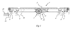
- Figure 1 represents a tube rail cart 1, at least without representing the superstructure which can be accomplished in various ways, for example by providing a work platform which is adjustable in height.
- the tube rail cart 1 includes a framework 2 onto which are provided four rail wheels 3, provided more specifically per pair here on a front axle 4 and a rear axle 5.
- the rail wheels 3 have a semicircular concaved contact surface such that, when seen in side-view, as represented in figure 1 , they keep the tube on which they rest partly hidden.
- a castor wheel 6 Near each of the rail wheels 3 is provided a castor wheel 6, more specifically moved further away from each other here, and thus provided closer to the longitudinal side edges of the tube rail cart 1 than the rail wheels 3, at least in the outwardly pivoted position thereof.
- Two drive sets 7 are provided here, mainly halfway through the front axle 4 and a rear axle 5, more specifically at an appropriate mutual distance, mainly corresponding to the mutual distance between the rail wheels 3 which are provided on one and the same axle.
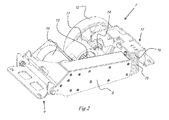
- each drive set 7 comprises a support arm 8 which can be hinge-mounted or pendulum-mounted on the framework 2 of the tube rail cart 1.
- a mounting bracket 9 is provided to this end in this embodiment, which can be provided on the framework 2 in a fixed manner and on which the support arm 8 can be pendulum-mounted, in this case at a far end of the support arm 8.
- a motor 10 On the support arm 8 are further provided a motor 10, a first drive wheel 11 having a first diameter and a second drive wheel 12 having a second diameter, whereby the first diameter is smaller than the second diameter.
- the first drive wheel 11 is provided on a first axle 13, whereas the second drive wheel 12 is provided on a second axle 14, which axles do not coincide here.
- first transmission Between the motor 10 and the first drive wheel 11 is provided a first transmission, and between the motor 10 and the second drive wheel 12 is provided a second transmission with an accompanying first and second transmission ratio.
- a spring 15 is provided between the support arm 8 and the framework 2.
- the spring 15 more specifically is a coil spring 15 here, provided around a cylindrical sleeve 16 which is provided on a guide bracket 17 which can be solidly fixed to the framework 2.
- the tube rail cart 1 is placed on a tube rail 18, which tube rail 18 is supported at regular distances by support legs 18B.
- the tube rail 18 is provided with a bend-shaped tube part 19 which connects the parallel tube parts of one and the same heating tube continuously.
- the bend-shaped tube part 19 rests on a hardened transverse path 20 or intermediate path, for example made of concrete.
- the top surface of the transverse path 20 is situated lower than the top side of the tubes of the tube rail 18, more specifically 51 millimetres lower in this case.
- the tubes of the tube rail 18 have an outer diameter of 51 millimetres here, but other common outer diameters are 45 millimetres or 57 millimetres.
- the first diameter of the first drive wheel 11 and the second diameter of the second drive wheel 12 are such that the difference between both is at least equal to, but preferably larger than the double of the diameter of the tubes.
- the first drive wheel 11 has a first diameter equal to 125 millimetres
- the second drive wheel 12 has a second diameter equal to 250 millimetres.
- the difference of 125 millimetres is indeed larger than twice the diameter of the tubes, in this case 102 millimetres.
- the tube rail cart 1 hereby not only rests on the rail wheels 3, but also on the centrally located first drive wheels 11 of both drive sets 7.
- the spring 15 presses the pendulum-mounted support arm 8 down at all times, in such a manner that even with downward bent rail tubes, the contact of the first drive wheel 11 with the tubes of the tube rail is still guaranteed.
- the castor wheels 6 will float on the outside of the tube rail 18, and also the second drive wheel 12 of each drive set 7 will float contact-free between the tubes of the tube rail 18.
- the front rail wheels 3 will first be moved past the bend-shaped tube part 19 and take place above the transverse path 20 in a free floating manner.
- the front castor wheels 6 will possibly be the first to make contact with the transverse path 20, although not necessarily, for example if the tube rail cart 1 were to rest on first drive wheels 11 and on the rear rail wheels 3 during the transition.
- the support arm 8 will be pushed upward until the final stop is reached, as a result of which the tube rail cart 1 is lifted somewhat.
- the speed of the tube rail cart 1 corresponds to the rotational speed multiplied by half the diameter of the active drive wheel 11 or 12.
- the ratio of the transmission ratios of the first transmission and the second transmission mainly correspond to the inverse ratio of the first diameter and the second diameter, the intended smooth transition from tube rail 18 to transverse path 20 is obtained.
- the user of the tube rail cart 1 according to the invention must not even step down from the tube rail cart 1 before the transition from the tube rails 18 to the hardened transverse path 20 is made.
- the tube rail cart 1 Once the tube rail cart 1 is situated entirely on the transverse path 20, which is obtained by moving the tube rail cart 1 mainly straight on as of the last-mentioned position, it will always rest entirely or partly on both second drive wheels 12, and optionally additionally on the front or rear set of castor wheels 6, or on both sets of castor wheels.
- the castor wheels 6 may have been provided at an appropriate height on the framework 2 to that end, adapted to the geometry, the dimensions and positioning of the support arm 8, the setting of the corresponding final stop and the diameter of the second drive wheel 12.
- the tube rail cart 1 according to the invention can be further manoeuvred, for example turned and driven further and turned again in front of the next tube rail 18, by controlling the motors 10 of the drive sets 7 in an appropriate manner, i.e. differently if a turn is to be taken.
- This simple control is an advantage which is obtained thanks to the positioning of the drive sets 7, i.e. between the front axle 4 and a rear axle 5.
- the drive sets 7 are provided mainly halfway between the front axle 4 and a rear axle 5, which position is preferred but not absolutely necessary.
- This intermediate position of drive sets 7, here in particular also the predominantly central position thereof, is also advantageous in that the load of the tube rail cart 1, when it is put on the tube rail 18, is distributed over six points of support.
- the drive wheels 11 and 12 can also be provided on a single axle, whereby planetary transmissions are used to obtain the different transmission ratios.
Landscapes
- Engineering & Computer Science (AREA)
- Transportation (AREA)
- Mechanical Engineering (AREA)
- Life Sciences & Earth Sciences (AREA)
- Environmental Sciences (AREA)
- Platform Screen Doors And Railroad Systems (AREA)
- Handcart (AREA)
Priority Applications (1)
| Application Number | Priority Date | Filing Date | Title |
|---|---|---|---|
| PL13168362T PL2664232T3 (pl) | 2012-05-18 | 2013-05-17 | Rurowy wózek szynowy |
Applications Claiming Priority (1)
| Application Number | Priority Date | Filing Date | Title |
|---|---|---|---|
| BE201200331A BE1020660A3 (nl) | 2012-05-18 | 2012-05-18 | Buisrailwagen. |
Publications (2)
| Publication Number | Publication Date |
|---|---|
| EP2664232A1 EP2664232A1 (en) | 2013-11-20 |
| EP2664232B1 true EP2664232B1 (en) | 2015-04-08 |
Family
ID=48326218
Family Applications (1)
| Application Number | Title | Priority Date | Filing Date |
|---|---|---|---|
| EP13168362.5A Active EP2664232B1 (en) | 2012-05-18 | 2013-05-17 | Tube rail cart |
Country Status (4)
| Country | Link |
|---|---|
| EP (1) | EP2664232B1 (pl) |
| BE (1) | BE1020660A3 (pl) |
| ES (1) | ES2536553T3 (pl) |
| PL (1) | PL2664232T3 (pl) |
Families Citing this family (4)
| Publication number | Priority date | Publication date | Assignee | Title |
|---|---|---|---|---|
| CN105028029B (zh) * | 2014-06-18 | 2017-09-29 | 寿光蔬菜产业控股集团有限公司 | 地热调风换气型日光温室 |
| BE1026985B1 (nl) * | 2019-01-21 | 2020-08-24 | B&A Automation Bvba | Aandrijving voor een buisrailwagen en combinatie van zulke aandrijving en een buisrailwagen |
| NL2024540B1 (en) * | 2019-12-20 | 2021-09-02 | Berg Product B V | Two-way horticulture trolley with individually turnable floor-wheels. |
| NL2027978B1 (en) * | 2021-04-15 | 2022-10-28 | Berg Product Systems B V | Horticulture trolley with slide bodies underneath a first and/or second head end of its frame. |
Family Cites Families (4)
| Publication number | Priority date | Publication date | Assignee | Title |
|---|---|---|---|---|
| NL1020506C2 (nl) * | 2002-05-01 | 2003-11-21 | Altech Logistiek B V | Werkwagen voor kassen. |
| EP1378381A1 (fr) * | 2002-07-01 | 2004-01-07 | Christian Louveau | Dispositif de guidage moteur et auto-directeur |
| DE20214353U1 (de) * | 2002-09-16 | 2002-11-14 | ZAGRO Bahn- und Baumaschinen GmbH, 74906 Bad Rappenau | Zweiwegefahrzeug mit einer Antriebseinrichtung für den Schienenbetrieb |
| DE102004057951B4 (de) * | 2004-11-30 | 2013-06-20 | Wolfgang Zappel | Zweiwegefahrzeug mit einer Antriebseinrichtung für den Schienenbetrieb |
-
2012
- 2012-05-18 BE BE201200331A patent/BE1020660A3/nl active
-
2013
- 2013-05-17 EP EP13168362.5A patent/EP2664232B1/en active Active
- 2013-05-17 PL PL13168362T patent/PL2664232T3/pl unknown
- 2013-05-17 ES ES13168362.5T patent/ES2536553T3/es active Active
Also Published As
| Publication number | Publication date |
|---|---|
| EP2664232A1 (en) | 2013-11-20 |
| PL2664232T3 (pl) | 2015-10-30 |
| ES2536553T3 (es) | 2015-05-26 |
| BE1020660A3 (nl) | 2014-02-04 |
Similar Documents
| Publication | Publication Date | Title |
|---|---|---|
| EP2664232B1 (en) | Tube rail cart | |
| CN105015639B (zh) | 跨行于高速公路中央分隔带护栏的自走式作业平台 | |
| CN203651758U (zh) | 一种山地单轨搬运车的地形自适应底轮装置 | |
| CN201296503Y (zh) | 蛇形移动带式输送机 | |
| CN205601804U (zh) | 小型汽车携升降平移器 | |
| CN202773869U (zh) | 驾驶座升降式高秆植物四轮喷药机 | |
| CN101758986B (zh) | 一种堆垛机以及一种轮对的固定和下料方法 | |
| CN100591554C (zh) | 一种平移小车及应用该平移小车的侧向平移泊车装置 | |
| CN111350392A (zh) | 一种用于立体车库的车辆交互机构 | |
| SE1200564A1 (sv) | Transport system | |
| CN204309968U (zh) | 一种果园专用电动三轮车 | |
| JP4966217B2 (ja) | 乗用水田作業機 | |
| CN206231439U (zh) | 一种微型四驱四轮转向大棚动力机 | |
| CN106275074B (zh) | 全地形履带式万向牵引转运机 | |
| CN114211922A (zh) | 一种高度可调悬臂装置及其车辆 | |
| CN208792845U (zh) | 一种升降横移载车板 | |
| WO2018129643A1 (zh) | 车辆及其底盘结构 | |
| DE102006061770A1 (de) | Einrad-Elektroantrieb | |
| CN102845404A (zh) | 驾驶座升降式高秆植物四轮喷药机 | |
| DE940533C (de) | Gleis-Wagenschieber | |
| IT202300002844A1 (it) | “dispositivo per il bloccaggio delle ruote, in particolare per il traino e/o la rimozione di un veicolo, e macchina per il traino e/o la movimentazione di un veicolo” | |
| CN208290964U (zh) | 一种重力势能驱动小车 | |
| CN204212477U (zh) | 一种机械车库车辆加固推送平台 | |
| CN105172926B (zh) | 以高速公路波形梁护栏为导轨且有越障能力的自走式作业平台 | |
| CN205884247U (zh) | 花卉洒水设备行进控制机构 |
Legal Events
| Date | Code | Title | Description |
|---|---|---|---|
| PUAI | Public reference made under article 153(3) epc to a published international application that has entered the european phase |
Free format text: ORIGINAL CODE: 0009012 |
|
| AK | Designated contracting states |
Kind code of ref document: A1 Designated state(s): AL AT BE BG CH CY CZ DE DK EE ES FI FR GB GR HR HU IE IS IT LI LT LU LV MC MK MT NL NO PL PT RO RS SE SI SK SM TR |
|
| AX | Request for extension of the european patent |
Extension state: BA ME |
|
| 17P | Request for examination filed |
Effective date: 20140520 |
|
| RBV | Designated contracting states (corrected) |
Designated state(s): AL AT BE BG CH CY CZ DE DK EE ES FI FR GB GR HR HU IE IS IT LI LT LU LV MC MK MT NL NO PL PT RO RS SE SI SK SM TR |
|
| GRAP | Despatch of communication of intention to grant a patent |
Free format text: ORIGINAL CODE: EPIDOSNIGR1 |
|
| INTG | Intention to grant announced |
Effective date: 20141022 |
|
| GRAS | Grant fee paid |
Free format text: ORIGINAL CODE: EPIDOSNIGR3 |
|
| GRAA | (expected) grant |
Free format text: ORIGINAL CODE: 0009210 |
|
| AK | Designated contracting states |
Kind code of ref document: B1 Designated state(s): AL AT BE BG CH CY CZ DE DK EE ES FI FR GB GR HR HU IE IS IT LI LT LU LV MC MK MT NL NO PL PT RO RS SE SI SK SM TR |
|
| REG | Reference to a national code |
Ref country code: GB Ref legal event code: FG4D |
|
| REG | Reference to a national code |
Ref country code: CH Ref legal event code: EP |
|
| REG | Reference to a national code |
Ref country code: IE Ref legal event code: FG4D |
|
| REG | Reference to a national code |
Ref country code: AT Ref legal event code: REF Ref document number: 719777 Country of ref document: AT Kind code of ref document: T Effective date: 20150515 |
|
| REG | Reference to a national code |
Ref country code: DE Ref legal event code: R096 Ref document number: 602013001436 Country of ref document: DE Effective date: 20150521 |
|
| REG | Reference to a national code |
Ref country code: ES Ref legal event code: FG2A Ref document number: 2536553 Country of ref document: ES Kind code of ref document: T3 Effective date: 20150526 |
|
| REG | Reference to a national code |
Ref country code: NL Ref legal event code: T3 |
|
| REG | Reference to a national code |
Ref country code: AT Ref legal event code: MK05 Ref document number: 719777 Country of ref document: AT Kind code of ref document: T Effective date: 20150408 |
|
| REG | Reference to a national code |
Ref country code: LT Ref legal event code: MG4D |
|
| PG25 | Lapsed in a contracting state [announced via postgrant information from national office to epo] |
Ref country code: LT Free format text: LAPSE BECAUSE OF FAILURE TO SUBMIT A TRANSLATION OF THE DESCRIPTION OR TO PAY THE FEE WITHIN THE PRESCRIBED TIME-LIMIT Effective date: 20150408 Ref country code: PT Free format text: LAPSE BECAUSE OF FAILURE TO SUBMIT A TRANSLATION OF THE DESCRIPTION OR TO PAY THE FEE WITHIN THE PRESCRIBED TIME-LIMIT Effective date: 20150810 Ref country code: NO Free format text: LAPSE BECAUSE OF FAILURE TO SUBMIT A TRANSLATION OF THE DESCRIPTION OR TO PAY THE FEE WITHIN THE PRESCRIBED TIME-LIMIT Effective date: 20150708 Ref country code: HR Free format text: LAPSE BECAUSE OF FAILURE TO SUBMIT A TRANSLATION OF THE DESCRIPTION OR TO PAY THE FEE WITHIN THE PRESCRIBED TIME-LIMIT Effective date: 20150408 Ref country code: FI Free format text: LAPSE BECAUSE OF FAILURE TO SUBMIT A TRANSLATION OF THE DESCRIPTION OR TO PAY THE FEE WITHIN THE PRESCRIBED TIME-LIMIT Effective date: 20150408 |
|
| REG | Reference to a national code |
Ref country code: PL Ref legal event code: T3 |
|
| PG25 | Lapsed in a contracting state [announced via postgrant information from national office to epo] |
Ref country code: LV Free format text: LAPSE BECAUSE OF FAILURE TO SUBMIT A TRANSLATION OF THE DESCRIPTION OR TO PAY THE FEE WITHIN THE PRESCRIBED TIME-LIMIT Effective date: 20150408 Ref country code: RS Free format text: LAPSE BECAUSE OF FAILURE TO SUBMIT A TRANSLATION OF THE DESCRIPTION OR TO PAY THE FEE WITHIN THE PRESCRIBED TIME-LIMIT Effective date: 20150408 Ref country code: IS Free format text: LAPSE BECAUSE OF FAILURE TO SUBMIT A TRANSLATION OF THE DESCRIPTION OR TO PAY THE FEE WITHIN THE PRESCRIBED TIME-LIMIT Effective date: 20150808 Ref country code: AT Free format text: LAPSE BECAUSE OF FAILURE TO SUBMIT A TRANSLATION OF THE DESCRIPTION OR TO PAY THE FEE WITHIN THE PRESCRIBED TIME-LIMIT Effective date: 20150408 Ref country code: GR Free format text: LAPSE BECAUSE OF FAILURE TO SUBMIT A TRANSLATION OF THE DESCRIPTION OR TO PAY THE FEE WITHIN THE PRESCRIBED TIME-LIMIT Effective date: 20150709 |
|
| REG | Reference to a national code |
Ref country code: DE Ref legal event code: R119 Ref document number: 602013001436 Country of ref document: DE |
|
| PG25 | Lapsed in a contracting state [announced via postgrant information from national office to epo] |
Ref country code: IT Free format text: LAPSE BECAUSE OF FAILURE TO SUBMIT A TRANSLATION OF THE DESCRIPTION OR TO PAY THE FEE WITHIN THE PRESCRIBED TIME-LIMIT Effective date: 20150408 Ref country code: DK Free format text: LAPSE BECAUSE OF FAILURE TO SUBMIT A TRANSLATION OF THE DESCRIPTION OR TO PAY THE FEE WITHIN THE PRESCRIBED TIME-LIMIT Effective date: 20150408 Ref country code: MC Free format text: LAPSE BECAUSE OF FAILURE TO SUBMIT A TRANSLATION OF THE DESCRIPTION OR TO PAY THE FEE WITHIN THE PRESCRIBED TIME-LIMIT Effective date: 20150408 Ref country code: EE Free format text: LAPSE BECAUSE OF FAILURE TO SUBMIT A TRANSLATION OF THE DESCRIPTION OR TO PAY THE FEE WITHIN THE PRESCRIBED TIME-LIMIT Effective date: 20150408 |
|
| PLBE | No opposition filed within time limit |
Free format text: ORIGINAL CODE: 0009261 |
|
| STAA | Information on the status of an ep patent application or granted ep patent |
Free format text: STATUS: NO OPPOSITION FILED WITHIN TIME LIMIT |
|
| REG | Reference to a national code |
Ref country code: IE Ref legal event code: MM4A |
|
| PG25 | Lapsed in a contracting state [announced via postgrant information from national office to epo] |
Ref country code: CZ Free format text: LAPSE BECAUSE OF FAILURE TO SUBMIT A TRANSLATION OF THE DESCRIPTION OR TO PAY THE FEE WITHIN THE PRESCRIBED TIME-LIMIT Effective date: 20150408 Ref country code: SK Free format text: LAPSE BECAUSE OF FAILURE TO SUBMIT A TRANSLATION OF THE DESCRIPTION OR TO PAY THE FEE WITHIN THE PRESCRIBED TIME-LIMIT Effective date: 20150408 Ref country code: RO Free format text: LAPSE BECAUSE OF NON-PAYMENT OF DUE FEES Effective date: 20150408 |
|
| 26N | No opposition filed |
Effective date: 20160111 |
|
| PG25 | Lapsed in a contracting state [announced via postgrant information from national office to epo] |
Ref country code: DE Free format text: LAPSE BECAUSE OF NON-PAYMENT OF DUE FEES Effective date: 20151201 Ref country code: IE Free format text: LAPSE BECAUSE OF NON-PAYMENT OF DUE FEES Effective date: 20150517 |
|
| REG | Reference to a national code |
Ref country code: FR Ref legal event code: PLFP Year of fee payment: 4 |
|
| PG25 | Lapsed in a contracting state [announced via postgrant information from national office to epo] |
Ref country code: SI Free format text: LAPSE BECAUSE OF FAILURE TO SUBMIT A TRANSLATION OF THE DESCRIPTION OR TO PAY THE FEE WITHIN THE PRESCRIBED TIME-LIMIT Effective date: 20150408 |
|
| PG25 | Lapsed in a contracting state [announced via postgrant information from national office to epo] |
Ref country code: BE Free format text: LAPSE BECAUSE OF FAILURE TO SUBMIT A TRANSLATION OF THE DESCRIPTION OR TO PAY THE FEE WITHIN THE PRESCRIBED TIME-LIMIT Effective date: 20150408 |
|
| PG25 | Lapsed in a contracting state [announced via postgrant information from national office to epo] |
Ref country code: MT Free format text: LAPSE BECAUSE OF FAILURE TO SUBMIT A TRANSLATION OF THE DESCRIPTION OR TO PAY THE FEE WITHIN THE PRESCRIBED TIME-LIMIT Effective date: 20150408 |
|
| REG | Reference to a national code |
Ref country code: CH Ref legal event code: PL |
|
| PG25 | Lapsed in a contracting state [announced via postgrant information from national office to epo] |
Ref country code: LI Free format text: LAPSE BECAUSE OF NON-PAYMENT OF DUE FEES Effective date: 20160531 Ref country code: CH Free format text: LAPSE BECAUSE OF NON-PAYMENT OF DUE FEES Effective date: 20160531 |
|
| REG | Reference to a national code |
Ref country code: FR Ref legal event code: PLFP Year of fee payment: 5 |
|
| PG25 | Lapsed in a contracting state [announced via postgrant information from national office to epo] |
Ref country code: BG Free format text: LAPSE BECAUSE OF FAILURE TO SUBMIT A TRANSLATION OF THE DESCRIPTION OR TO PAY THE FEE WITHIN THE PRESCRIBED TIME-LIMIT Effective date: 20150408 Ref country code: HU Free format text: LAPSE BECAUSE OF FAILURE TO SUBMIT A TRANSLATION OF THE DESCRIPTION OR TO PAY THE FEE WITHIN THE PRESCRIBED TIME-LIMIT; INVALID AB INITIO Effective date: 20130517 |
|
| PG25 | Lapsed in a contracting state [announced via postgrant information from national office to epo] |
Ref country code: CY Free format text: LAPSE BECAUSE OF FAILURE TO SUBMIT A TRANSLATION OF THE DESCRIPTION OR TO PAY THE FEE WITHIN THE PRESCRIBED TIME-LIMIT Effective date: 20150408 Ref country code: SE Free format text: LAPSE BECAUSE OF FAILURE TO SUBMIT A TRANSLATION OF THE DESCRIPTION OR TO PAY THE FEE WITHIN THE PRESCRIBED TIME-LIMIT Effective date: 20150408 |
|
| PG25 | Lapsed in a contracting state [announced via postgrant information from national office to epo] |
Ref country code: LU Free format text: LAPSE BECAUSE OF NON-PAYMENT OF DUE FEES Effective date: 20150517 |
|
| GBPC | Gb: european patent ceased through non-payment of renewal fee |
Effective date: 20170517 |
|
| PG25 | Lapsed in a contracting state [announced via postgrant information from national office to epo] |
Ref country code: GB Free format text: LAPSE BECAUSE OF NON-PAYMENT OF DUE FEES Effective date: 20170517 |
|
| REG | Reference to a national code |
Ref country code: FR Ref legal event code: PLFP Year of fee payment: 6 |
|
| PG25 | Lapsed in a contracting state [announced via postgrant information from national office to epo] |
Ref country code: SM Free format text: LAPSE BECAUSE OF FAILURE TO SUBMIT A TRANSLATION OF THE DESCRIPTION OR TO PAY THE FEE WITHIN THE PRESCRIBED TIME-LIMIT Effective date: 20150408 |
|
| PG25 | Lapsed in a contracting state [announced via postgrant information from national office to epo] |
Ref country code: MK Free format text: LAPSE BECAUSE OF FAILURE TO SUBMIT A TRANSLATION OF THE DESCRIPTION OR TO PAY THE FEE WITHIN THE PRESCRIBED TIME-LIMIT Effective date: 20150408 |
|
| PG25 | Lapsed in a contracting state [announced via postgrant information from national office to epo] |
Ref country code: AL Free format text: LAPSE BECAUSE OF FAILURE TO SUBMIT A TRANSLATION OF THE DESCRIPTION OR TO PAY THE FEE WITHIN THE PRESCRIBED TIME-LIMIT Effective date: 20150408 |
|
| P01 | Opt-out of the competence of the unified patent court (upc) registered |
Effective date: 20230404 |
|
| REG | Reference to a national code |
Ref country code: NL Ref legal event code: HC Owner name: BOGAERTS NEXT ENGINEERING B.V.; BE Free format text: DETAILS ASSIGNMENT: CHANGE OF OWNER(S), CHANGE OF OWNER(S) NAME; FORMER OWNER NAME: B&A AUTOMATION BVBA Effective date: 20240628 |
|
| PGFP | Annual fee paid to national office [announced via postgrant information from national office to epo] |
Ref country code: TR Payment date: 20240513 Year of fee payment: 12 |
|
| PGFP | Annual fee paid to national office [announced via postgrant information from national office to epo] |
Ref country code: NL Payment date: 20250522 Year of fee payment: 13 |
|
| PGFP | Annual fee paid to national office [announced via postgrant information from national office to epo] |
Ref country code: PL Payment date: 20250505 Year of fee payment: 13 |
|
| PGFP | Annual fee paid to national office [announced via postgrant information from national office to epo] |
Ref country code: ES Payment date: 20250616 Year of fee payment: 13 |
|
| PGFP | Annual fee paid to national office [announced via postgrant information from national office to epo] |
Ref country code: FR Payment date: 20250521 Year of fee payment: 13 |