EP2662174B1 - Rohrförmiges Schraubwerkzeug zum Einschrauben einer mit Außengewinde versehenen Hohlschraube in eine Bohrung - Google Patents
Rohrförmiges Schraubwerkzeug zum Einschrauben einer mit Außengewinde versehenen Hohlschraube in eine Bohrung Download PDFInfo
- Publication number
- EP2662174B1 EP2662174B1 EP13167110.9A EP13167110A EP2662174B1 EP 2662174 B1 EP2662174 B1 EP 2662174B1 EP 13167110 A EP13167110 A EP 13167110A EP 2662174 B1 EP2662174 B1 EP 2662174B1
- Authority
- EP
- European Patent Office
- Prior art keywords
- screwing
- hollow screw
- screwing tool
- tubular
- spreading
- Prior art date
- Legal status (The legal status is an assumption and is not a legal conclusion. Google has not performed a legal analysis and makes no representation as to the accuracy of the status listed.)
- Not-in-force
Links
Images

Classifications
-
- B—PERFORMING OPERATIONS; TRANSPORTING
- B23—MACHINE TOOLS; METAL-WORKING NOT OTHERWISE PROVIDED FOR
- B23G—THREAD CUTTING; WORKING OF SCREWS, BOLT HEADS, OR NUTS, IN CONJUNCTION THEREWITH
- B23G5/00—Thread-cutting tools; Die-heads
- B23G5/02—Thread-cutting tools; Die-heads without means for adjustment
- B23G5/06—Taps
-
- B—PERFORMING OPERATIONS; TRANSPORTING
- B23—MACHINE TOOLS; METAL-WORKING NOT OTHERWISE PROVIDED FOR
- B23G—THREAD CUTTING; WORKING OF SCREWS, BOLT HEADS, OR NUTS, IN CONJUNCTION THEREWITH
- B23G5/00—Thread-cutting tools; Die-heads
- B23G5/08—Thread-cutting tools; Die-heads with means for adjustment
- B23G5/14—Tapping-heads
-
- B—PERFORMING OPERATIONS; TRANSPORTING
- B25—HAND TOOLS; PORTABLE POWER-DRIVEN TOOLS; MANIPULATORS
- B25B—TOOLS OR BENCH DEVICES NOT OTHERWISE PROVIDED FOR, FOR FASTENING, CONNECTING, DISENGAGING, OR HOLDING
- B25B13/00—Spanners; Wrenches
- B25B13/02—Spanners; Wrenches with rigid jaws
- B25B13/06—Spanners; Wrenches with rigid jaws of socket type
-
- B—PERFORMING OPERATIONS; TRANSPORTING
- B25—HAND TOOLS; PORTABLE POWER-DRIVEN TOOLS; MANIPULATORS
- B25B—TOOLS OR BENCH DEVICES NOT OTHERWISE PROVIDED FOR, FOR FASTENING, CONNECTING, DISENGAGING, OR HOLDING
- B25B13/00—Spanners; Wrenches
- B25B13/48—Spanners; Wrenches for special purposes
-
- B—PERFORMING OPERATIONS; TRANSPORTING
- B25—HAND TOOLS; PORTABLE POWER-DRIVEN TOOLS; MANIPULATORS
- B25B—TOOLS OR BENCH DEVICES NOT OTHERWISE PROVIDED FOR, FOR FASTENING, CONNECTING, DISENGAGING, OR HOLDING
- B25B31/00—Hand tools for applying fasteners
Definitions
- the invention relates to a tubular screwing tool for screwing an externally threaded hollow screw into a bore in a component.
- hollow screws are often used in automotive headlamps for holding lighting fixtures.
- This must form a thread that matches the external thread of the hollow screw, which usually causes a distortion of the material of the component.
- chips are usually in the context of further use of the screwed hollow screw a problem, they are usually sucked, but this is only completely successful if the chips do not settle in the threads both the hollow screw and the component.
- a raw screwing tool according to the preamble of claim 1 is made DE 20 2010 005 703 U1 known.
- An expandable tap which is as far as expandable when screwed into the bore, that he forms a seated on spreading external thread that cuts by spreading its components with the rotation of a driving pin an internal thread into the bore into which a hollow screw is screwed, is off DE 17 52 190 A1 known
- the cutting of the internal thread is designed in a special way so that the inevitably forming chips can be removed in a particularly favorable manner.
- the screwing tool has a driving bolt passing through the hollow bolt, wherein the driving pin is provided with a driving profile, and further comprises the driving pin at its protruding from the hollow screw end an expandable tap, which is as far as spread apart when screwed into the bore that this forms a seated on spreading parts male thread, which cuts by spreading its components with the rotation of the driving pin an internal thread into the bore into which the hollow screw is screwed.
- the chip formation is created by the expandable taps. Since this protrudes after cutting the internal thread of the hollow screw while the spreading parts are relatively wide open, this end of the tap is free for a flow of air, so that any chips adhering there can either be easily sucked off or blown off.
- the driving pin has a longitudinal bore, in which an axially displaceable spreading means is guided.
- the spreading comprises at its end facing the tap an expansion cone, which merges into a spreader, which in particular projects through the driving pin.
- the spreader itself can be penetrated by channels of any cross-section. By providing the channels, a material and / or weight saving of the spreading is achieved.
- the channels are designed in particular as holes.
- the channels may preferably be designed such that they allow the blowing or suction of the resulting chips during the cutting process, which can be dispensed with the handling of additional suction or Abblas wornen.
- a movement limitation may be provided on the spreading means, which allows an accurate and reproducible adjustment of the thread diameter.
- the screwing tool may have a screw means, on the one hand rotatably connected to the driving pin, on the other hand can be brought into engagement with the head of the hollow screw. This can be done with the screwing both a Vortex the thread with the tap and the screwing of the hollow screw in one step.
- the screw means may be designed for an external drive or an internal drive.
- the screw can be displaced in the axial direction and spring-loaded in the axial direction.
- the spring parameters are selected such that the spring yields to the component at a certain contact pressure of the hollow screw. This contact pressure is chosen so that it is less than the contact pressure necessary for cutting a thread with the hollow screw. As a result, the automatic cutting of a thread is prevented by the hollow screw.
- the hollow screw then rotates with reduced contact pressure on the surface of the component until it engages in the pre-cut through the tap thread and is screwed, which usually takes place after a maximum of one revolution.
- the spring parameters such as. Length, diameter, spring constant, etc., can be designed depending on the application.
- the hollow screw 1 which has a through hole 2, and which is externally threaded, which is composed of individual segments, which goes back to the production of this hollow screw 1.
- the screwing tool Before the through hole 2, the screwing tool is arranged, comprising a Aufsp Drailleus 3 with spreader bar 5 and a driving pin 6 with a longitudinal bore 4, wherein the driving pin 6 is penetrated by the spreader bar 5.
- the screwing tool comprises a tap 7, which is arranged on the driving pin 6 and a Cutting thread 15 has that matches the thread in the hollow screw.
- the spreader rod 5 protrudes on the one hand on the opposite end of the Aufsp Schwarzkonus 3 and goes on the other side in the Aufsp Dr Drillkonus 3 over.
- On the Aufsp Dr Dr Dr Drus 3 facing away from the screw has the driving profile 6a, which consists of a hexagon here.
- FIG. 2 the same screwing is shown, however, with this deferred hollow screw 1.
- the screwing a position that precedes as a starting point for later screwing the hollow screw.
- holes 20 are provided in the spreading, which are set up for the passage of an air flow.
- the expansion means by being connected to a blow-off or suction device, can remove chips directly at their point of origin.
- Fig. 3a the screwing tool is shown with spread tap 7.
- the tap 7 consists here of the spreading parts 9 to 14, which are provided with an inner cone on which the spreading means consisting of spreader bar 5 and Aufsp Dr Dr Dr Dr Dr Dr Dr Dr Dramus 3, acts with the Aufsp Drirrius 3, whereby the individual expansion parts 9 to 14 to a larger diameter arrange cutting threads 15 which is then used to cut a thread (see Fig. 4 ).
- the Fig. 3b shows the axial plan view
- Essential in this design is that the individual expansion parts 9 to 14 after cutting the thread (see Fig. 4 ) are present in a spread state, so that a directed to the relevant end of the screwing air flow at this point somehow adhering chips resulting from the tapping can easily be blown away or sucked, so that then after unscrewing and removing the screwing a component is present to the adhere no chips, so that in the cut thread in this component, the hollow screw can be screwed.
- the screwing tool is provided with a screwing means which is designed as an externally driving nut 17.
- the nut 17 is rotatably connected to the driving profile 6a and engages around the head of the hollow screw. By rotation of the driving profile 6a, the hollow screw 1 will now be screwed to the component 16.
- Fig. 5 shows the state after completion of screwing.
- Fig. 8 shows an embodiment of the screwing tool, wherein the nut 17 in the axial direction against a spring 18 acts.
- the nut 17 is rotatably guided by another driving profile 6b.
- the spring 18 is supported via a socket 19 with respect to the driving profile 6 in the axial direction.
- the spring parameters of the spring 18 are designed such that the spring 18 only allows the application of a contact pressure on the hollow screw 1, which is less than the contact pressure, which would be necessary for an automatic cutting of a thread.
- Fig. 8 shows the operating case in which the applied pressure is absorbed by the spring 18, whereby the hollow screw 1 rotates so long on the surface of the component 16 until the hollow screw 1 engages the previously cut thread and this is screwed, without even a second To cut threads.
- Fig. 9 shows the spring 18 in a relaxed state. As shown here, only a small contact pressure for screwing the hollow screw 1 in the thread is necessary. This contact pressure is imparted to the hollow screw 1 depending on the spring parameters. The spring 18 is relieved in the screwed state and moves the nut 17 relative to the driving pin 6 in the direction of the hollow screw first
Landscapes
- Engineering & Computer Science (AREA)
- Mechanical Engineering (AREA)
- Processing Of Stones Or Stones Resemblance Materials (AREA)
- Hand Tools For Fitting Together And Separating, Or Other Hand Tools (AREA)
- Bridges Or Land Bridges (AREA)
Description
- Die Erfindung bezieht sich auf ein rohrförmiges Schraubwerkzeug zum Einschrauben einer mit Außengewinde versehenen Hohlschraube in eine Bohrung in einem Bauteil. Derartige Hohlschrauben werden häufig in Kraftfahrzeugscheinwerfern zur Halterung von Beleuchtungskörpern verwendet. Beim Einschrauben einer mit Außengewinde versehenen Hohlschraube in eine Bohrung ergibt sich häufig das Problem, dass beim Eindrehen der Hohlschraube diese sich ein Gewinde ausformen muss, das zu dem Außengewinde der Hohlschraube passt, wobei in der Regel eine Verspanung des Materials des Bauteils eintritt. Derartige Späne sind meist im Rahmen der weiteren Verwendung der eingeschraubten Hohlschraube ein Problem, sie werden in der Regel abgesaugt, was allerdings auch nur dann vollständig erfolgreich ist, wenn die Späne sich nicht in den Gewindegängen sowohl der Hohlschraube als auch des Bauteils festsetzen.
- Ein rohförmiges Schraubwerkzeug gemäß dem Oberbegriff des Anspruchs 1 ist aus
DE 20 2010 005 703 U1 bekannt. Ein aufspreizbarer Gewindebohrer, der beim Eindrehen in die Bohrung soweit aufspreizbar ist, dass er ein auf Aufspreizteilen sitzendes Außengewinde bildet, das durch Aufspreizen seiner Bestandteile mit der Drehung eines Mitnahmebolzens ein Innengewinde in die Bohrung schneidet, in das eine Hohlschraube eindrehbar ist, ist ausDE 17 52 190 A1 bekannt - Durch die Erfindung wird in besonderer Weise das Schneiden des Innengewindes so gestaltet, dass die sich zwangsläufig ausbildenden Späne in besonders günstiger Weise entfernt werden können. Dies geschieht dadurch, dass das Schraubwerkzeug einen die Hohlschraube durchsetzenden Mitnahmebolzen aufweist, wobei der Mitnahmebolzen mit einem Mitnahmeprofil versehen ist, und ferner der Mitnahmebolzen an seinem aus der Hohlschraube herausragenden Ende einen aufspreizbaren Gewindebohrer aufweist, der beim Eindrehen in die Bohrung soweit aufspreizbar ist, dass dieser ein auf Aufspreizteilen sitzendes Außengewinde bildet, das durch Aufspreizen seiner Bestandteile mit der Drehung des Mitnahmebolzens ein Innengewinde in die Bohrung schneidet, in das die Hohlschraube eindrehbar ist.
- Die Spanbildung entsteht dabei durch den aufspreizbaren Gewindebohrer. Da dieser nach Schneiden des Innengewindes aus der Hohlschraube herausragt und dabei die Aufspreizteile relativ weit geöffnet sind, liegt dieses Ende des Gewindebohrers für einen Luftstrom frei, so dass irgendwelche dort haftenden Späne problemlos entweder abgesogen oder abgeblasen werden können.
- Vorzugsweise weist der Mitnahmebolzen eine Längsbohrung auf, in welcher ein axial verschiebbares Spreizmittel geführt ist. Das Spreizmittel umfasst an seinem, dem Gewindebohrer zugewandten Ende einen Spreizkonus, der in eine Spreizstange übergeht, die insbesondere den Mitnahmebolzen durchragt. Durch eine axiale Verschiebung des Spreizmittels in Richtung des Gewindebohrers erfolgt dessen Aufspreizung. Ferner kann das Spreizmittel selbst von Kanälen eines beliebigen Querschnitts durchsetzt sein. Durch das Vorsehen der Kanäle wird eine Material- und / oder Gewichtsersparnis des Spreizmittels erzielt. Die Kanäle sind insbesondere als Bohrungen ausgebildet.
- Die Kanäle können vorzugsweise derart ausgebildet sein, dass sie das Abblasen oder Absaugen der während des Schneidvorgangs entstehenden Späne ermöglichen, wodurch auf die Handhabung zusätzlicher Absaug- oder Abblaseinrichtungen verzichtet werden kann.
- Zusätzlich kann an dem Spreizmittel eine Bewegungsbegrenzung vorgesehen sein, die eine genaue und reproduzierbare Einstellung des Gewindedurchmessers erlaubt.
- Ferner kann das Schraubwerkzeug ein Schraubmittel aufweisen, das einerseits drehfest mit dem Mitnahmebolzen verbindbar ist, andererseits mit dem Kopf der Hohlschraube in Eingriff gebracht werden kann. Dadurch kann mit dem Schraubwerkzeug sowohl ein Vorschneiden des Gewindes mit dem Gewindebohrer als auch das Einschrauben der Hohlschraube in einem Arbeitsschritt erfolgen. Das Schraubmittel kann für einen Außenantrieb oder einen Innenantrieb ausgebildet sein.
- In einer besonders vorteilhaften Ausführungsform, kann das Schraubmittel in axialer Richtung verschiebbar und in axialer Richtung federbelastet sein. Die Federparameter sind derart gewählt, dass die Feder bei einem bestimmten Anpressdruck der Hohlschraube an das Bauteil nachgibt. Dieser Anpressdruck ist so gewählt, dass er geringer ist als der für das Schneiden eines Gewindes mit der Hohlschraube notwendige Anpressdruck. Dadurch wird das selbsttätige Schneiden eines Gewindes durch die Hohlschraube verhindert. Die Hohlschraube dreht dann mit vermindertem Anpressdruck so lange an der Oberfläche des Bauteils bis es in das durch den Gewindebohrer vorgeschnittene Gewinde eingreift und eingedreht wird, was in der Regel nach höchstens einer Umdrehung erfolgt. Die Federparameter, wie bspw. Länge, Durchmesser, Federkonstante etc., können abhängig vom Anwendungsfall ausgelegt werden.
- In den Figuren ist ein Ausführungsbeispiel der Erfindung dargestellt. Es zeigen:
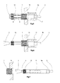
- Fig. 1
- das Schraubwerkzeug mit aus diesem axial herausragenden Aufspreizkonus und vor dem Aufspreizkonus angeordneter Hohlschraube;
- Fig. 2
- die Gestaltung gemäß
Fig. 1 mit auf das Schraubwerkzeug aufgeschobener Hohlschraube; - Fig. 2a
- eine Schnittansicht des Aufspreizkonus mit Bohrungen;
- Fig. 3a
- die Gestaltung gemäß
Fig. 2 mit in das Schraubwerkzeug eingezogenem Aufspreizkonus; - Fig. 3b
- eine Draufsicht auf die Seite des Schraubwerkzeuges mit dem Aufspreizkonus;
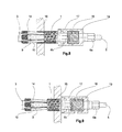
- Fig. 4
- die Gestaltung gemäß
Fig. 3 mit aufgespreiztem Gewindebohrer und durch das Bauteil hindurch geschraubtem und damit geschnittenem Gewinde; - Fig. 5
- das Bauteil mit eingeschraubter Hohlschraube und hindurch getretenem, aufgespreiztem Gewindebohrer;
- Fig. 6
- die eingeschraubte Hohlschraube mit zusammengezogenem Gewindebohrer;
- Fig. 7
- das Bauteil mit eingeschraubter Hohlschraube und durch diese hindurch gezogenem Aufspreizkonus;
- Fig. 8
- das Schraubwerkzeug mit Anpressdruckregulation im gespannten Zustand, und
- Fig. 9
- das Schraubwerkzeug nach
Fig. 8 mit Anpressdruckregulation im entspannten Zustand. - In der
Fig. 1 ist die Hohlschraube 1 dargestellt, die ein Durchgangsloch 2 aufweist, und die außen mit einem Gewinde versehen ist, das aus einzelnen Segmenten zusammengesetzt ist, was auf die Herstellung dieser Hohlschraube 1 zurückgeht. Vor dem Durchgangsloch 2 ist das Schraubwerkzeug angeordnet, umfassend einen Aufspreizkonus 3 mit Spreizstange 5 und einen Mitnahmebolzen 6 mit einer Längsbohrung 4, wobei der Mitnahmebolzen 6 von der Spreizstange 5 durchsetzt wird. Ferner umfasst das Schraubwerkzeug einen Gewindebohrer 7, der am Mitnahmebolzen 6 angeordnet ist und ein Schneidgewinde 15 aufweist, das zu dem Gewinde in der Hohlschraube passt. Die Spreizstange 5 ragt einerseits auf dem dem Aufspreizkonus 3 gegenüberliegenden Ende heraus und geht auf der anderen Seite in den Aufspreizkonus 3 über. Auf dem Aufspreizkonus 3 abgewandten Ende besitzt das Schraubwerkzeug das Mitnahmeprofil 6a, das hier aus einem Sechskant besteht. - In der
Fig. 2 ist das gleiche Schraubwerkzeug dargestellt, allerdings mit auf dieses aufgeschobener Hohlschraube 1. Damit weist das Schraubwerkzeug eine Lage auf, die als Ausgangslage für das spätere Einschrauben der Hohlschraube vorangeht. In derFig. 2 und Fig. 2a sind Bohrungen 20 im Spreizmittel vorgesehen, welche für den Durchlass eines Luftstroms eingerichtet sind. Das Spreizmittel kann, indem es an eine Abblas- oder Absaugeinrichtung angeschlossen wird, Späne direkt an ihrem Entstehungsort entfernen. - In
Fig. 3a ist das Schraubwerkzeug mit aufgespreiztem Gewindebohrer 7 dargestellt. Der Gewindebohrer 7 besteht hier aus den Aufspreizteilen 9 bis 14, die mit einem Innenkonus versehen sind, auf den das Spreizmittel bestehend aus Spreizstange 5 und Aufspreizkonus 3, mit dem Aufspreizkonus 3 wirkt, wodurch sich die einzelnen Aufspreizteile 9 bis 14 zu einem einen größeren Durchmesser aufweisenden Schneidgewinde 15 anordnen, das dann zum Schneiden eines Gewindes verwendet wird (sieheFig. 4 ). - Die Gestaltung gemäß
Fig. 3a wird jetzt unter Drehung des Mitnahmeprofils 6a in die Durchgangsbohrung 8 des Bauteils 16 eingeführt, wodurch die einzelnen Aufspreizteile 9 bis 14 des Gewindebohrers 7 gemäß ihrer äußeren Form, das in derFigur 4 deutlich dargestellte Gewinde schneiden. Damit hat das Bauteil 16 das erforderliche Innengewinde erhalten, so dass es später das Einschrauben der Hohlschraube 1 ermöglicht. - Die
Fig. 3b zeigt die axiale Draufsicht auf den Aufspreizkonus 3 und die diesen umgebenden Kranz der Aufspreizteile 9 bis 14. - Wesentlich bei dieser Gestaltung ist, dass die einzelnen Aufspreizteile 9 bis 14 nach Schneiden des Gewindes (siehe
Fig. 4 ) in gespreiztem Zustand vorliegen, so dass ein auf das betreffende Ende des Schraubwerkzeugs gerichteter Luftstrom an dieser Stelle irgendwie haftende Späne, die von dem Gewindeschneiden herrühren, problemlos weggeblasen oder abgesaugt werden können, so dass anschließend nach Herausdrehen und Wegführen des Schraubwerkzeugs ein Bauteil vorliegt, an dem keinerlei Späne haften, so dass in das geschnittene Gewinde in diesem Bauteil die Hohlschraube eingedreht werden kann. - Das gemäß
Fig. 4 eingeschnittene Gewinde erlaubt jetzt das Eindrehen der Hohlschraube 1 in das Gewinde des Bauteils. Zur Durchführung des Schraubvorgangs, ist das Schraubwerkzeug mit einem Schraubmittel versehen, welches als außenantreibende Nuss 17 ausgebildet ist. Die Nuss 17 ist drehfest mit dem Mitnahmeprofil 6a verbunden und umgreift den Kopf der Hohlschraube. Durch Drehung des Mitnahmeprofils 6a wird nun die Hohlschraube 1 mit dem Bauteil 16 verschraubt werden. -
Fig. 5 zeigt den Zustand nach erfolgtem Einschraubvorgang. - Der Vorgang des Rückführens des Schraubwerkzeugs mit zurückgeführtem Aufspreizkonus 3 wird in den
Figs. 6 und 7 gezeigt. Nach dem Einschraubvorgang wird dann der Aufspreizkonus 3 vom Schneidgewinde 15 weggeschoben, wodurch die Aufspreizteile 9 bis 14 des Gewindebohrers 7 wieder in die ursprüngliche Lage zusammenrücken und damit die Rückführung des Schraubwerkzeugs in eine Lage ermöglichen, wie sie inFigur 7 dargestellt ist. Hier wird die Hohlschraube 1 in das Bauteil 16 vollständig eingeschraubt und das Schraubwerkzeug mit seinem Aufspreizkonus 3 vor dem Bauteil 16 liegend und frei von diesem dargestellt. -
Fig. 8 zeigt eine Ausführung des Schraubwerkzeugs, bei welchem die Nuss 17 in axialer Richtung gegen eine Feder 18 wirkt. Die Nuss 17 wird durch ein weiteres Mitnahmeprofil 6b drehfest geführt. Die Feder 18 stützt sich über eine Fassung 19 gegenüber dem Mitnahmeprofil 6 in axialer Richtung ab. Die Federparameter der Feder 18 sind derart ausgelegt, dass die Feder 18 lediglich die Ausübung eines Anpressdrucks auf die Hohlschraube 1 zulässt, der geringer ist als der Anpressdruck, der für ein selbsttätiges Schneiden eines Gewindes notwendig wäre.Fig. 8 zeigt den Betriebsfall, bei dem der aufgebrachte Druck von der Feder 18 aufgenommen wird, wodurch sich die Hohlschraube 1 so lange an der Oberfläche des Bauteils 16 dreht, bis die Hohlschraube 1 in das zuvor geschnittene Gewinde eingreift und dieses eingeschraubt wird, ohne selbst ein zweites Gewinde zu schneiden. -
Fig. 9 zeigt die Feder 18 in einem entlasteten Zustand. Wie hier dargestellt, ist nur ein geringer Anpressdruck für das Einschrauben der Hohlschraube 1 in das Gewinde notwendig. Dieser Anpressdruck wird abhängig von den Federparametern an die Hohlschraube 1 vermittelt. Die Feder 18 wird im eingeschraubten Zustand entlastet und verschiebt die Nuss 17 relativ zum Mitnahmebolzen 6 in Richtung der Hohlschraube 1.
Claims (6)
- Rohrförmiges Schraubwerkzeug zum Einschrauben einer mit Außengewinde versehenen Hohlschraube (1) in eine Bohrung (8) in einem Bauteil (16), dadurch gekennzeichnet, dass das Schraubwerkzeug einen die Hohlschraube (1) durchsetzenden Mitnahmebolzen (6) mit einem Mitnahmeprofil (6a) aufweist, der an seinem aus der Hohlschraube (1) herausragenden Ende einen aufspreizbaren Gewindebohrer (7) aufweist, der beim Eindrehen in die Bohrung (8) soweit aufspreizbar ist, dass dieser ein auf Aufspreizteilen (9 bis 14) sitzendes Außengewinde (15) bildet, das durch Aufspreizen seiner Bestandteile mit der Drehung des Mitnahmebolzens (6) ein Innengewinde in die Bohrung (8) schneidet, in das die Hohlschraube (1) eindrehbar ist.
- Rohrförmiges Schraubwerkzeug nach Anspruch 1, dadurch gekennzeichnet, dass der Mitnahmebolzen (6) eine Längsbohrung (4) aufweist, in welcher ein Spreizmittel, umfassend einen Aufspreizkonus (3) und eine Spreizstange (5), geführt ist.
- Rohrförmiges Schraubwerkzeug nach Anspruch 2, dadurch gekennzeichnet, dass der Gewindebohrer (7) durch eine axiale Verschiebung des Aufspreizkonus (3) in Richtung des Gewindebohrers (7) aufgespreizbar ist.
- Rohrförmiges Schraubwerkzeug nach Anspruche 2 oder 3, dadurch gekennzeichnet, dass das Spreizmittel mit Kanälen (20) durchsetzt ist, welche eingerichtet sind einen Luftstrom zu führen.
- Rohrförmiges Schraubwerkzeug nach einem der vorangehenden Ansprüche, dadurch gekennzeichnet, dass ein Schraubmittel (17) zum Verschrauben der Hohlschraube (1) vorgesehen ist, welches drehfest mit dem Mitnahmebolzen (6) verbunden ist.
- Rohrförmiges Schraubwerkzeug nach Anspruch 5, dadurch gekennzeichnet, dass eine Feder (18) vorgesehen ist, welche ein in axiale Richtung verschiebbares Schraubmittel (17) in axialer Richtung mit einer Federkraft beaufschlagt.
Applications Claiming Priority (1)
| Application Number | Priority Date | Filing Date | Title |
|---|---|---|---|
| DE201210104050 DE102012104050A1 (de) | 2012-05-09 | 2012-05-09 | Rohrförmiges Schraubwerkzeug zum Einschrauben einer mit Außengewinde versehenen Hohlschraube in eine Bohrung |
Publications (2)
| Publication Number | Publication Date |
|---|---|
| EP2662174A1 EP2662174A1 (de) | 2013-11-13 |
| EP2662174B1 true EP2662174B1 (de) | 2015-07-15 |
Family
ID=48366198
Family Applications (1)
| Application Number | Title | Priority Date | Filing Date |
|---|---|---|---|
| EP13167110.9A Not-in-force EP2662174B1 (de) | 2012-05-09 | 2013-05-08 | Rohrförmiges Schraubwerkzeug zum Einschrauben einer mit Außengewinde versehenen Hohlschraube in eine Bohrung |
Country Status (3)
| Country | Link |
|---|---|
| EP (1) | EP2662174B1 (de) |
| DE (1) | DE102012104050A1 (de) |
| ES (1) | ES2544741T3 (de) |
Families Citing this family (6)
| Publication number | Priority date | Publication date | Assignee | Title |
|---|---|---|---|---|
| CN104400753A (zh) * | 2014-11-30 | 2015-03-11 | 重庆锦冈机械有限公司 | 水泵预埋紧固系统 |
| CN108942796A (zh) * | 2018-09-06 | 2018-12-07 | 爱克斯瑞真空技术(苏州)有限公司 | 一种无头螺丝内拉器 |
| CN109332008B (zh) * | 2018-11-06 | 2020-12-01 | 岳欣 | 一种方便对试管进行固定的血液检测用离心机 |
| DE102021109198A1 (de) | 2021-04-13 | 2022-10-13 | KEIL Befestigungstechnik GmbH | Hinterschnittanker, Setzwerkzeug zum Setzen eines Hinterschnittankers und Setzverfahren für einen Hinterschnittanker |
| CN115156642B (zh) * | 2022-04-18 | 2026-03-24 | 北京航天卓越精密机械制造有限公司 | 一种用于加工5g螺纹的6h丝锥改装方法及改装丝锥 |
| CN121514622B (zh) * | 2026-01-14 | 2026-04-14 | 浙江方泉汽车标准件股份有限公司 | 一种螺母生产用内螺纹加工设备 |
Family Cites Families (7)
| Publication number | Priority date | Publication date | Assignee | Title |
|---|---|---|---|---|
| US3322005A (en) * | 1939-12-29 | 1967-05-30 | Neuschotz Robert | Tool for installing expandable threaded element |
| US2616103A (en) * | 1947-02-08 | 1952-11-04 | Henry D Stecher | Method of boring and tapping |
| DE1752190A1 (de) * | 1968-04-18 | 1971-03-18 | Fadispel Fabricadora De Dispos | Verfahren und Vorrichtung zum Herstellen von Innengewinden |
| US5281059A (en) * | 1993-02-08 | 1994-01-25 | Gary Stuckle | Tool for repairing damaged threads in a blind hole |
| US5617623A (en) * | 1995-05-24 | 1997-04-08 | Jergens, Inc. | Installation tool for keylocking inserts |
| US20110259158A1 (en) * | 2010-04-25 | 2011-10-27 | Perry James Richardson | Dual Hex Pattern Wrench |
| DE202010005703U1 (de) * | 2010-06-23 | 2010-11-18 | JOYI CO., LTD., Taiping City | Steckschlüsseleinsatz |
-
2012
- 2012-05-09 DE DE201210104050 patent/DE102012104050A1/de not_active Withdrawn
-
2013
- 2013-05-08 EP EP13167110.9A patent/EP2662174B1/de not_active Not-in-force
- 2013-05-08 ES ES13167110.9T patent/ES2544741T3/es active Active
Also Published As
| Publication number | Publication date |
|---|---|
| DE102012104050A1 (de) | 2013-11-14 |
| ES2544741T3 (es) | 2015-09-03 |
| EP2662174A1 (de) | 2013-11-13 |
Similar Documents
| Publication | Publication Date | Title |
|---|---|---|
| EP3025807B1 (de) | Nietwerkzeug | |
| EP2662174A1 (de) | Rohrförmiges Schraubwerkzeug zum Einschrauben einer mit Außengewinde versehenen Hohlschraube in eine Bohrung | |
| EP1215404B1 (de) | Befestigungsvorrichtung für ein an einer Platte zu befestigendes Bauteil | |
| DE102014100697A1 (de) | Verfahren zum Setzen einer Blindnietmutter mit Toleranzausgleichselement | |
| DE10200964B4 (de) | System zum Verbinden zweier Profilstäbe | |
| DE102012108779A1 (de) | Profilverbindung | |
| DE2909749A1 (de) | Duebel und werkzeug zum befestigen des duebels | |
| EP1911550B1 (de) | Vorrichtung zum Zentrieren einer Kupplungsscheibe einer Kraftfahrzeugkupplung | |
| EP2825780B1 (de) | Spreizanker | |
| DE102007025745B4 (de) | Werkzeugsatz, Bohrer und Verfahren zum Ausbohren von defekten Glühkerzen | |
| DE102010048776A1 (de) | Schraubenhalterung | |
| DE102011102363B4 (de) | Vorrichtung zum Ausziehen einer Einspritzdüse | |
| DE10234603B4 (de) | Spanneinrichtung für Werkzeuge oder Werkstücke | |
| WO2003004832A1 (de) | Befestigungsanordnung für einen schneidmeissel | |
| DE102013103429A1 (de) | Dämmstoffhalter | |
| DE10142438A1 (de) | Befestigungsanordnung | |
| EP2894355A1 (de) | Mehrteiliger Dämmstoffanker mit Rastverschluss | |
| EP2527666B1 (de) | Spreizanker | |
| DE202015004749U1 (de) | Vorrichtung zum Befestigen einer Bohrhülse | |
| DE3022755A1 (de) | Gewindeschneidvorrichtung mit erhoehtem ansetzdruck | |
| DE2126621C3 (de) | Spann- und Lösevorrichtung für einen konischen Schaft aufweisende Werkzeuge | |
| DE102009021633B3 (de) | Befestigungselement | |
| DE102009021632B3 (de) | Befestigungselement | |
| DE202008007342U1 (de) | Nietausbohrwerkzeug mit Nietsicherung | |
| DE102016106801B4 (de) | Vorrichtung zum Setzen von Spreiznieten |
Legal Events
| Date | Code | Title | Description |
|---|---|---|---|
| PUAI | Public reference made under article 153(3) epc to a published international application that has entered the european phase |
Free format text: ORIGINAL CODE: 0009012 |
|
| AK | Designated contracting states |
Kind code of ref document: A1 Designated state(s): AL AT BE BG CH CY CZ DE DK EE ES FI FR GB GR HR HU IE IS IT LI LT LU LV MC MK MT NL NO PL PT RO RS SE SI SK SM TR |
|
| AX | Request for extension of the european patent |
Extension state: BA ME |
|
| RIN1 | Information on inventor provided before grant (corrected) |
Inventor name: ACHENBACH, MICHAEL Inventor name: KELLER, KARL-GEORG |
|
| 17P | Request for examination filed |
Effective date: 20140415 |
|
| RBV | Designated contracting states (corrected) |
Designated state(s): AL AT BE BG CH CY CZ DE DK EE ES FI FR GB GR HR HU IE IS IT LI LT LU LV MC MK MT NL NO PL PT RO RS SE SI SK SM TR |
|
| REG | Reference to a national code |
Ref country code: DE Ref legal event code: R079 Ref document number: 502013000878 Country of ref document: DE Free format text: PREVIOUS MAIN CLASS: B23G0009000000 Ipc: B25B0031000000 |
|
| GRAP | Despatch of communication of intention to grant a patent |
Free format text: ORIGINAL CODE: EPIDOSNIGR1 |
|
| INTG | Intention to grant announced |
Effective date: 20150212 |
|
| RIC1 | Information provided on ipc code assigned before grant |
Ipc: B23G 5/06 20060101ALI20150130BHEP Ipc: B25B 13/06 20060101ALI20150130BHEP Ipc: B25B 31/00 20060101AFI20150130BHEP Ipc: B25B 13/48 20060101ALI20150130BHEP Ipc: B23G 5/14 20060101ALI20150130BHEP |
|
| GRAS | Grant fee paid |
Free format text: ORIGINAL CODE: EPIDOSNIGR3 |
|
| GRAA | (expected) grant |
Free format text: ORIGINAL CODE: 0009210 |
|
| AK | Designated contracting states |
Kind code of ref document: B1 Designated state(s): AL AT BE BG CH CY CZ DE DK EE ES FI FR GB GR HR HU IE IS IT LI LT LU LV MC MK MT NL NO PL PT RO RS SE SI SK SM TR |
|
| REG | Reference to a national code |
Ref country code: CH Ref legal event code: EP Ref country code: GB Ref legal event code: FG4D Free format text: NOT ENGLISH |
|
| REG | Reference to a national code |
Ref country code: IE Ref legal event code: FG4D Free format text: LANGUAGE OF EP DOCUMENT: GERMAN |
|
| REG | Reference to a national code |
Ref country code: AT Ref legal event code: REF Ref document number: 736533 Country of ref document: AT Kind code of ref document: T Effective date: 20150815 |
|
| REG | Reference to a national code |
Ref country code: DE Ref legal event code: R096 Ref document number: 502013000878 Country of ref document: DE Ref country code: ES Ref legal event code: FG2A Ref document number: 2544741 Country of ref document: ES Kind code of ref document: T3 Effective date: 20150903 |
|
| REG | Reference to a national code |
Ref country code: NL Ref legal event code: MP Effective date: 20150715 |
|
| REG | Reference to a national code |
Ref country code: LT Ref legal event code: MG4D |
|
| PG25 | Lapsed in a contracting state [announced via postgrant information from national office to epo] |
Ref country code: GR Free format text: LAPSE BECAUSE OF FAILURE TO SUBMIT A TRANSLATION OF THE DESCRIPTION OR TO PAY THE FEE WITHIN THE PRESCRIBED TIME-LIMIT Effective date: 20151016 Ref country code: NO Free format text: LAPSE BECAUSE OF FAILURE TO SUBMIT A TRANSLATION OF THE DESCRIPTION OR TO PAY THE FEE WITHIN THE PRESCRIBED TIME-LIMIT Effective date: 20151015 Ref country code: LV Free format text: LAPSE BECAUSE OF FAILURE TO SUBMIT A TRANSLATION OF THE DESCRIPTION OR TO PAY THE FEE WITHIN THE PRESCRIBED TIME-LIMIT Effective date: 20150715 Ref country code: FI Free format text: LAPSE BECAUSE OF FAILURE TO SUBMIT A TRANSLATION OF THE DESCRIPTION OR TO PAY THE FEE WITHIN THE PRESCRIBED TIME-LIMIT Effective date: 20150715 Ref country code: LT Free format text: LAPSE BECAUSE OF FAILURE TO SUBMIT A TRANSLATION OF THE DESCRIPTION OR TO PAY THE FEE WITHIN THE PRESCRIBED TIME-LIMIT Effective date: 20150715 |
|
| PG25 | Lapsed in a contracting state [announced via postgrant information from national office to epo] |
Ref country code: PL Free format text: LAPSE BECAUSE OF FAILURE TO SUBMIT A TRANSLATION OF THE DESCRIPTION OR TO PAY THE FEE WITHIN THE PRESCRIBED TIME-LIMIT Effective date: 20150715 Ref country code: PT Free format text: LAPSE BECAUSE OF FAILURE TO SUBMIT A TRANSLATION OF THE DESCRIPTION OR TO PAY THE FEE WITHIN THE PRESCRIBED TIME-LIMIT Effective date: 20151116 Ref country code: RS Free format text: LAPSE BECAUSE OF FAILURE TO SUBMIT A TRANSLATION OF THE DESCRIPTION OR TO PAY THE FEE WITHIN THE PRESCRIBED TIME-LIMIT Effective date: 20150715 Ref country code: SE Free format text: LAPSE BECAUSE OF FAILURE TO SUBMIT A TRANSLATION OF THE DESCRIPTION OR TO PAY THE FEE WITHIN THE PRESCRIBED TIME-LIMIT Effective date: 20150715 Ref country code: HR Free format text: LAPSE BECAUSE OF FAILURE TO SUBMIT A TRANSLATION OF THE DESCRIPTION OR TO PAY THE FEE WITHIN THE PRESCRIBED TIME-LIMIT Effective date: 20150715 |
|
| REG | Reference to a national code |
Ref country code: DE Ref legal event code: R097 Ref document number: 502013000878 Country of ref document: DE |
|
| PG25 | Lapsed in a contracting state [announced via postgrant information from national office to epo] |
Ref country code: DK Free format text: LAPSE BECAUSE OF FAILURE TO SUBMIT A TRANSLATION OF THE DESCRIPTION OR TO PAY THE FEE WITHIN THE PRESCRIBED TIME-LIMIT Effective date: 20150715 Ref country code: CZ Free format text: LAPSE BECAUSE OF FAILURE TO SUBMIT A TRANSLATION OF THE DESCRIPTION OR TO PAY THE FEE WITHIN THE PRESCRIBED TIME-LIMIT Effective date: 20150715 Ref country code: SK Free format text: LAPSE BECAUSE OF FAILURE TO SUBMIT A TRANSLATION OF THE DESCRIPTION OR TO PAY THE FEE WITHIN THE PRESCRIBED TIME-LIMIT Effective date: 20150715 Ref country code: EE Free format text: LAPSE BECAUSE OF FAILURE TO SUBMIT A TRANSLATION OF THE DESCRIPTION OR TO PAY THE FEE WITHIN THE PRESCRIBED TIME-LIMIT Effective date: 20150715 Ref country code: IT Free format text: LAPSE BECAUSE OF FAILURE TO SUBMIT A TRANSLATION OF THE DESCRIPTION OR TO PAY THE FEE WITHIN THE PRESCRIBED TIME-LIMIT Effective date: 20150715 |
|
| PLBE | No opposition filed within time limit |
Free format text: ORIGINAL CODE: 0009261 |
|
| STAA | Information on the status of an ep patent application or granted ep patent |
Free format text: STATUS: NO OPPOSITION FILED WITHIN TIME LIMIT |
|
| PG25 | Lapsed in a contracting state [announced via postgrant information from national office to epo] |
Ref country code: RO Free format text: LAPSE BECAUSE OF FAILURE TO SUBMIT A TRANSLATION OF THE DESCRIPTION OR TO PAY THE FEE WITHIN THE PRESCRIBED TIME-LIMIT Effective date: 20150715 |
|
| 26N | No opposition filed |
Effective date: 20160418 |
|
| PG25 | Lapsed in a contracting state [announced via postgrant information from national office to epo] |
Ref country code: IS Free format text: LAPSE BECAUSE OF FAILURE TO SUBMIT A TRANSLATION OF THE DESCRIPTION OR TO PAY THE FEE WITHIN THE PRESCRIBED TIME-LIMIT Effective date: 20150715 |
|
| PG25 | Lapsed in a contracting state [announced via postgrant information from national office to epo] |
Ref country code: BE Free format text: LAPSE BECAUSE OF NON-PAYMENT OF DUE FEES Effective date: 20160531 Ref country code: SI Free format text: LAPSE BECAUSE OF FAILURE TO SUBMIT A TRANSLATION OF THE DESCRIPTION OR TO PAY THE FEE WITHIN THE PRESCRIBED TIME-LIMIT Effective date: 20150715 |
|
| PG25 | Lapsed in a contracting state [announced via postgrant information from national office to epo] |
Ref country code: LU Free format text: LAPSE BECAUSE OF FAILURE TO SUBMIT A TRANSLATION OF THE DESCRIPTION OR TO PAY THE FEE WITHIN THE PRESCRIBED TIME-LIMIT Effective date: 20160508 |
|
| REG | Reference to a national code |
Ref country code: CH Ref legal event code: PL |
|
| PG25 | Lapsed in a contracting state [announced via postgrant information from national office to epo] |
Ref country code: CH Free format text: LAPSE BECAUSE OF NON-PAYMENT OF DUE FEES Effective date: 20160531 Ref country code: LI Free format text: LAPSE BECAUSE OF NON-PAYMENT OF DUE FEES Effective date: 20160531 |
|
| REG | Reference to a national code |
Ref country code: IE Ref legal event code: MM4A |
|
| REG | Reference to a national code |
Ref country code: FR Ref legal event code: ST Effective date: 20170131 |
|
| PG25 | Lapsed in a contracting state [announced via postgrant information from national office to epo] |
Ref country code: FR Free format text: LAPSE BECAUSE OF NON-PAYMENT OF DUE FEES Effective date: 20160531 |
|
| PG25 | Lapsed in a contracting state [announced via postgrant information from national office to epo] |
Ref country code: IE Free format text: LAPSE BECAUSE OF NON-PAYMENT OF DUE FEES Effective date: 20160508 |
|
| PG25 | Lapsed in a contracting state [announced via postgrant information from national office to epo] |
Ref country code: NL Free format text: LAPSE BECAUSE OF FAILURE TO SUBMIT A TRANSLATION OF THE DESCRIPTION OR TO PAY THE FEE WITHIN THE PRESCRIBED TIME-LIMIT Effective date: 20150715 |
|
| PGFP | Annual fee paid to national office [announced via postgrant information from national office to epo] |
Ref country code: DE Payment date: 20170530 Year of fee payment: 5 |
|
| GBPC | Gb: european patent ceased through non-payment of renewal fee |
Effective date: 20170508 |
|
| PG25 | Lapsed in a contracting state [announced via postgrant information from national office to epo] |
Ref country code: GB Free format text: LAPSE BECAUSE OF NON-PAYMENT OF DUE FEES Effective date: 20170508 |
|
| PG25 | Lapsed in a contracting state [announced via postgrant information from national office to epo] |
Ref country code: CY Free format text: LAPSE BECAUSE OF FAILURE TO SUBMIT A TRANSLATION OF THE DESCRIPTION OR TO PAY THE FEE WITHIN THE PRESCRIBED TIME-LIMIT Effective date: 20150715 Ref country code: HU Free format text: LAPSE BECAUSE OF FAILURE TO SUBMIT A TRANSLATION OF THE DESCRIPTION OR TO PAY THE FEE WITHIN THE PRESCRIBED TIME-LIMIT; INVALID AB INITIO Effective date: 20130508 Ref country code: SM Free format text: LAPSE BECAUSE OF FAILURE TO SUBMIT A TRANSLATION OF THE DESCRIPTION OR TO PAY THE FEE WITHIN THE PRESCRIBED TIME-LIMIT Effective date: 20150715 Ref country code: ES Free format text: LAPSE BECAUSE OF NON-PAYMENT OF DUE FEES Effective date: 20160509 |
|
| REG | Reference to a national code |
Ref country code: ES Ref legal event code: FD2A Effective date: 20180625 |
|
| PG25 | Lapsed in a contracting state [announced via postgrant information from national office to epo] |
Ref country code: TR Free format text: LAPSE BECAUSE OF FAILURE TO SUBMIT A TRANSLATION OF THE DESCRIPTION OR TO PAY THE FEE WITHIN THE PRESCRIBED TIME-LIMIT Effective date: 20150715 Ref country code: MK Free format text: LAPSE BECAUSE OF FAILURE TO SUBMIT A TRANSLATION OF THE DESCRIPTION OR TO PAY THE FEE WITHIN THE PRESCRIBED TIME-LIMIT Effective date: 20150715 Ref country code: MC Free format text: LAPSE BECAUSE OF FAILURE TO SUBMIT A TRANSLATION OF THE DESCRIPTION OR TO PAY THE FEE WITHIN THE PRESCRIBED TIME-LIMIT Effective date: 20150715 Ref country code: MT Free format text: LAPSE BECAUSE OF FAILURE TO SUBMIT A TRANSLATION OF THE DESCRIPTION OR TO PAY THE FEE WITHIN THE PRESCRIBED TIME-LIMIT Effective date: 20150715 |
|
| PG25 | Lapsed in a contracting state [announced via postgrant information from national office to epo] |
Ref country code: BG Free format text: LAPSE BECAUSE OF FAILURE TO SUBMIT A TRANSLATION OF THE DESCRIPTION OR TO PAY THE FEE WITHIN THE PRESCRIBED TIME-LIMIT Effective date: 20150715 |
|
| PG25 | Lapsed in a contracting state [announced via postgrant information from national office to epo] |
Ref country code: AL Free format text: LAPSE BECAUSE OF FAILURE TO SUBMIT A TRANSLATION OF THE DESCRIPTION OR TO PAY THE FEE WITHIN THE PRESCRIBED TIME-LIMIT Effective date: 20150715 |
|
| REG | Reference to a national code |
Ref country code: DE Ref legal event code: R119 Ref document number: 502013000878 Country of ref document: DE |
|
| PG25 | Lapsed in a contracting state [announced via postgrant information from national office to epo] |
Ref country code: DE Free format text: LAPSE BECAUSE OF NON-PAYMENT OF DUE FEES Effective date: 20181201 |
|
| REG | Reference to a national code |
Ref country code: AT Ref legal event code: MM01 Ref document number: 736533 Country of ref document: AT Kind code of ref document: T Effective date: 20180508 |
|
| PG25 | Lapsed in a contracting state [announced via postgrant information from national office to epo] |
Ref country code: AT Free format text: LAPSE BECAUSE OF NON-PAYMENT OF DUE FEES Effective date: 20180508 |