EP2660914A1 - Fuel cell system - Google Patents
Fuel cell system Download PDFInfo
- Publication number
- EP2660914A1 EP2660914A1 EP11853595.4A EP11853595A EP2660914A1 EP 2660914 A1 EP2660914 A1 EP 2660914A1 EP 11853595 A EP11853595 A EP 11853595A EP 2660914 A1 EP2660914 A1 EP 2660914A1
- Authority
- EP
- European Patent Office
- Prior art keywords
- air
- housing
- discharge path
- path
- fuel cell
- Prior art date
- Legal status (The legal status is an assumption and is not a legal conclusion. Google has not performed a legal analysis and makes no representation as to the accuracy of the status listed.)
- Withdrawn
Links
Images


Classifications
-
- H—ELECTRICITY
- H01—ELECTRIC ELEMENTS
- H01M—PROCESSES OR MEANS, e.g. BATTERIES, FOR THE DIRECT CONVERSION OF CHEMICAL ENERGY INTO ELECTRICAL ENERGY
- H01M8/00—Fuel cells; Manufacture thereof
- H01M8/04—Auxiliary arrangements, e.g. for control of pressure or for circulation of fluids
- H01M8/04082—Arrangements for control of reactant parameters, e.g. pressure or concentration
- H01M8/04089—Arrangements for control of reactant parameters, e.g. pressure or concentration of gaseous reactants
-
- H—ELECTRICITY
- H01—ELECTRIC ELEMENTS
- H01M—PROCESSES OR MEANS, e.g. BATTERIES, FOR THE DIRECT CONVERSION OF CHEMICAL ENERGY INTO ELECTRICAL ENERGY
- H01M8/00—Fuel cells; Manufacture thereof
- H01M8/04—Auxiliary arrangements, e.g. for control of pressure or for circulation of fluids
-
- H—ELECTRICITY
- H01—ELECTRIC ELEMENTS
- H01M—PROCESSES OR MEANS, e.g. BATTERIES, FOR THE DIRECT CONVERSION OF CHEMICAL ENERGY INTO ELECTRICAL ENERGY
- H01M8/00—Fuel cells; Manufacture thereof
- H01M8/04—Auxiliary arrangements, e.g. for control of pressure or for circulation of fluids
- H01M8/04007—Auxiliary arrangements, e.g. for control of pressure or for circulation of fluids related to heat exchange
- H01M8/04067—Heat exchange or temperature measuring elements, thermal insulation, e.g. heat pipes, heat pumps, fins
-
- H—ELECTRICITY
- H01—ELECTRIC ELEMENTS
- H01M—PROCESSES OR MEANS, e.g. BATTERIES, FOR THE DIRECT CONVERSION OF CHEMICAL ENERGY INTO ELECTRICAL ENERGY
- H01M8/00—Fuel cells; Manufacture thereof
- H01M8/10—Fuel cells with solid electrolytes
-
- H—ELECTRICITY
- H01—ELECTRIC ELEMENTS
- H01M—PROCESSES OR MEANS, e.g. BATTERIES, FOR THE DIRECT CONVERSION OF CHEMICAL ENERGY INTO ELECTRICAL ENERGY
- H01M8/00—Fuel cells; Manufacture thereof
- H01M8/10—Fuel cells with solid electrolytes
- H01M8/12—Fuel cells with solid electrolytes operating at high temperature, e.g. with stabilised ZrO2 electrolyte
-
- H—ELECTRICITY
- H01—ELECTRIC ELEMENTS
- H01M—PROCESSES OR MEANS, e.g. BATTERIES, FOR THE DIRECT CONVERSION OF CHEMICAL ENERGY INTO ELECTRICAL ENERGY
- H01M8/00—Fuel cells; Manufacture thereof
- H01M8/24—Grouping of fuel cells, e.g. stacking of fuel cells
- H01M8/2465—Details of groupings of fuel cells
- H01M8/247—Arrangements for tightening a stack, for accommodation of a stack in a tank or for assembling different tanks
- H01M8/2475—Enclosures, casings or containers of fuel cell stacks
-
- H—ELECTRICITY
- H01—ELECTRIC ELEMENTS
- H01M—PROCESSES OR MEANS, e.g. BATTERIES, FOR THE DIRECT CONVERSION OF CHEMICAL ENERGY INTO ELECTRICAL ENERGY
- H01M8/00—Fuel cells; Manufacture thereof
- H01M8/10—Fuel cells with solid electrolytes
- H01M2008/1095—Fuel cells with polymeric electrolytes
-
- H—ELECTRICITY
- H01—ELECTRIC ELEMENTS
- H01M—PROCESSES OR MEANS, e.g. BATTERIES, FOR THE DIRECT CONVERSION OF CHEMICAL ENERGY INTO ELECTRICAL ENERGY
- H01M8/00—Fuel cells; Manufacture thereof
- H01M8/10—Fuel cells with solid electrolytes
- H01M8/12—Fuel cells with solid electrolytes operating at high temperature, e.g. with stabilised ZrO2 electrolyte
- H01M2008/1293—Fuel cells with solid oxide electrolytes
-
- H—ELECTRICITY
- H01—ELECTRIC ELEMENTS
- H01M—PROCESSES OR MEANS, e.g. BATTERIES, FOR THE DIRECT CONVERSION OF CHEMICAL ENERGY INTO ELECTRICAL ENERGY
- H01M8/00—Fuel cells; Manufacture thereof
- H01M8/04—Auxiliary arrangements, e.g. for control of pressure or for circulation of fluids
- H01M8/04007—Auxiliary arrangements, e.g. for control of pressure or for circulation of fluids related to heat exchange
- H01M8/04014—Heat exchange using gaseous fluids; Heat exchange by combustion of reactants
- H01M8/04022—Heating by combustion
-
- H—ELECTRICITY
- H01—ELECTRIC ELEMENTS
- H01M—PROCESSES OR MEANS, e.g. BATTERIES, FOR THE DIRECT CONVERSION OF CHEMICAL ENERGY INTO ELECTRICAL ENERGY
- H01M8/00—Fuel cells; Manufacture thereof
- H01M8/06—Combination of fuel cells with means for production of reactants or for treatment of residues
- H01M8/0606—Combination of fuel cells with means for production of reactants or for treatment of residues with means for production of gaseous reactants
- H01M8/0612—Combination of fuel cells with means for production of reactants or for treatment of residues with means for production of gaseous reactants from carbon-containing material
- H01M8/0618—Reforming processes, e.g. autothermal, partial oxidation or steam reforming
-
- H—ELECTRICITY
- H01—ELECTRIC ELEMENTS
- H01M—PROCESSES OR MEANS, e.g. BATTERIES, FOR THE DIRECT CONVERSION OF CHEMICAL ENERGY INTO ELECTRICAL ENERGY
- H01M8/00—Fuel cells; Manufacture thereof
- H01M8/08—Fuel cells with aqueous electrolytes
- H01M8/086—Phosphoric acid fuel cells [PAFC]
-
- Y—GENERAL TAGGING OF NEW TECHNOLOGICAL DEVELOPMENTS; GENERAL TAGGING OF CROSS-SECTIONAL TECHNOLOGIES SPANNING OVER SEVERAL SECTIONS OF THE IPC; TECHNICAL SUBJECTS COVERED BY FORMER USPC CROSS-REFERENCE ART COLLECTIONS [XRACs] AND DIGESTS
- Y02—TECHNOLOGIES OR APPLICATIONS FOR MITIGATION OR ADAPTATION AGAINST CLIMATE CHANGE
- Y02E—REDUCTION OF GREENHOUSE GAS [GHG] EMISSIONS, RELATED TO ENERGY GENERATION, TRANSMISSION OR DISTRIBUTION
- Y02E60/00—Enabling technologies; Technologies with a potential or indirect contribution to GHG emissions mitigation
- Y02E60/30—Hydrogen technology
- Y02E60/50—Fuel cells
Definitions
- the present invention relates to a fuel cell system.
- Patent Literature 1 discloses a fuel cell system that includes a power generating unit including a cell stack, a housing that accommodates the power generating unit, a fan that introduces air from the outside of the housing to the inside of the housing, and a blower that supplies the air to the cathode of the cell stack.
- a power generating unit including a cell stack
- a housing that accommodates the power generating unit
- a fan that introduces air from the outside of the housing to the inside of the housing
- a blower that supplies the air to the cathode of the cell stack.
- ventilation and cooling of the inside of the housing are realized by introducing air from the outside of the housing to the inside of the housing.
- Patent Literature 1 Japanese Patent Application Laid-open No. 2007-207441
- such a housing that accommodates the power generating unit as described above may be required to have air-tightness from the perspective of, for example, installing the fuel cell system in a facility.
- introduction of gas into the housing from a path other than an exclusive gas introduction path and discharge of gas from the housing through a path other than an exclusive gas discharge path are not allowed.
- a fan that introduces air from the outside of the housing to the inside of the housing cannot be provided in the housing.
- an object of the present invention is to provide a fuel cell system capable of efficiently cooling a power generating unit accommodated in a housing even if the housing that accommodates the power generating unit has air-tightness.
- a fuel cell system including: a power generating unit including a cell stack for performing power generation by using hydrogen-containing gas; a housing for accommodating the power generating unit; an air introduction path for introducing air to be supplied to a cathode of the cell stack, from an outside of the housing to an inside of the housing; an air flow path for causing the air introduced to the inside of the housing through the air introduction path to flow in the inside of the housing, and to transfer heat from the power generating unit to the air so as to cool the power generating unit; a blower provided downstream of the air flow path so as to supply the air to the cathode; and an air supply path provided downstream from the blower so as to cause the air to be supplied to the cathode by the blower to flow.
- the housing accommodating the power generating unit has air-tightness.
- the air-tightness means such properties that the housing is tightly sealed against outside air other than gas that is to be introduced into the housing (air or the like introduced from the outside of the housing to the inside of the housing through the air introduction path).
- the housing having air-tightness means a housing in which introduction of gas into the housing is realized through an exclusive gas introduction path and discharge of gas from the housing is realized through an exclusive gas discharge path.
- a fuel cell system 1 includes a desulfurizing unit 2, a vaporizing unit 3, a hydrogen generating unit 4, a cell stack 5, an off-gas combusting unit 6, a hydrogen-containing fuel supply unit 7, a water supply unit 8, an oxidant supply unit 9, a power conditioner 10, and a control unit 11.
- the cell stack 5 performs power generation using hydrogen-containing fuel and oxidant.
- the type of the cell stack 5 in the fuel cell system 1 is not particularly limited, and for example, a polymer electrolyte fuel cell (PEFC), a solid oxide fuel cell (SOFC), a phosphoric acid fuel cell (PAFC), a molten carbonate fuel cell (MCFC), and other types of fuel cells can be used.
- PEFC polymer electrolyte fuel cell
- SOFC solid oxide fuel cell
- PAFC phosphoric acid fuel cell
- MCFC molten carbonate fuel cell
- the constituent components shown in Fig. 1 may be appropriately omitted depending on the type of the cell stack 5, the type of hydrogen-containing
- hydrocarbon-based fuel is used, for example.
- hydrocarbon-based fuel compounds containing carbon and hydrogen (the compounds may contain other elements such as oxygen) in their molecules and mixtures thereof are used.
- the hydrocarbon-based fuel include hydrocarbons, alcohols, ethers, and biofuel, and hydrocarbon-based fuels that originate from existing fossil fuels such as petroleum or coal, that originate from synthetic fuels such as synthetic gas, and that originate from biomass can be appropriately used.
- hydrocarbons include methane, ethane, propane, butane, natural gas, liquefied petroleum gas (LPG), city gas, town gas, gasoline, naphtha, kerosene, and gas oil.
- LPG liquefied petroleum gas
- examples of alcohols include methanol and ethanol.
- ethers include dimethyl ether.
- biofuel include biogas, bioethanol, biodiesel, and bio jet.
- oxygen-enriched air As the oxidant, air, pure oxygen gas (may contain impurities that are rarely removed by a general removal method), and oxygen-enriched air are used.
- the desulfurizing unit 2 desulfurizes the hydrogen-containing fuel supplied to the hydrogen generating unit 4.
- the desulfurizing unit 2 has a desulfurizing catalyst for removing sulfurated compounds contained in the hydrogen-containing fuel.
- a desulfurization method of the desulfurizing unit 2 an adsorptive desulfurization method of adsorbing and removing sulfurated compounds and a hydrodesulfurization method of allowing sulfurated compounds to react with hydrogen to remove the sulfurated compounds are used, for example.
- the desulfurizing unit 2 supplies the desulfurized hydrogen-containing fuel to the hydrogen generating unit 4.
- the vaporizing unit 3 generates steam supplied to the hydrogen generating unit 4 by heating and vaporizing water.
- heat generated within the fuel cell system 1 such as heat of the hydrogen generating unit 4, heat of the off-gas combusting unit 6, or heat recovered from exhaust gas may be used.
- water may be heated using additional heat sources such as a heater or a burner.
- the hydrogen generating unit 4 generates hydrogen-rich gas using the hydrogen-containing fuel from the desulfurizing unit 2.
- the hydrogen generating unit 4 has a reformer that reforms the hydrogen-containing fuel using a reforming catalyst.
- a reforming method used in the hydrogen generating unit 4 is not particularly limited, and for example, steam reforming, partial oxidation reforming, autothermal reforming, and other reforming methods can be used.
- the hydrogen generating unit 4 may include a configuration for adjusting properties in addition to the reformer that reforms the hydrogen-containing fuel using the reforming catalyst depending on the properties of the hydrogen-rich gas required for the cell stack 5.
- the hydrogen generating unit 4 includes a configuration (for example, a shift reactor and a selective oxidation reactor) for removing carbon monoxides in the hydrogen-rich gas.
- the hydrogen generating unit 4 supplies the hydrogen-rich gas to an anode 12 of the cell stack 5.
- the cell stack 5 performs power generation using the hydrogen-rich gas from the hydrogen generating unit 4 and the oxidant from the oxidant supply unit 9.
- the cell stack 5 includes the anode 12 to which the hydrogen-rich gas is supplied, a cathode 13 to which the oxidant is supplied, and an electrolyte 14 disposed between the anode 12 and the cathode 13.
- the cell stack 5 supplies electric power to the outside via the power conditioner 10.
- the cell stack 5 supplies hydrogen-rich gas and oxidant that were not used for power generation to the off-gas combusting unit 6 as off-gas.
- a combusting unit (for example, a combustor or the like that heats the reformer) included in the hydrogen generating unit 4 may be used as the off-gas combusting unit 6.
- the off-gas combusting unit 6 combusts the off-gas supplied from the cell stack 5.
- the heat generated by the off-gas combusting unit 6 is supplied to the hydrogen generating unit 4 and is used for generation of the hydrogen-rich gas in the hydrogen generating unit 4.
- the hydrogen-containing fuel supply unit 7 supplies the hydrogen-containing fuel to the desulfurizing unit 2.
- the water supply unit 8 supplies water to the vaporizing unit 3.
- the oxidant supply unit 9 supplies the oxidant to the cathode 13 of the cell stack 5.
- the hydrogen-containing fuel supply unit 7, the water supply unit 8, and the oxidant supply unit 9 are configured as a pump, for example, and are driven based on a control signal from the control unit 11.
- the power conditioner 10 adjusts the electric power from the cell stack 5 according to a power consumption state on the outside.
- the power conditioner 10 performs a process of converting a voltage and a process of converting a DC power into an AC power, for example.
- hydrogen-containing fuel for example, pure hydrogen gas, hydrogen-enriched gas, and the like
- hydrogen-containing fuel supply unit 7 one or a plurality of the desulfurizing unit 2, the water supply unit 8, the vaporizing unit 3, and the hydrogen generating unit 4 may not be provided.
- the control unit 11 performs a process of controlling the entire fuel cell system 1.
- the control unit 11 is configured as a device that includes a central processing unit (CPU), a read only memory (ROM), a random access memory (RAM), and an input/output interface.
- the control unit 11 is electrically connected to the hydrogen-containing fuel supply unit 7, the water supply unit 8, the oxidant supply unit 9, the power conditioner 10, and other sensors and auxiliary devices (not shown).
- the control unit 11 gets various signals generated within the fuel cell system 1 and outputs a control signal to respective devices in the fuel cell system 1.
- the fuel cell system 1 includes a housing 21 having air-tightness with respect to outside air.
- the housing 21 accommodates the above-described devices including the power generating unit 22.
- the power generating unit 22 is a module that includes the cell stack 5 that generates power by using the hydrogen-rich gas (hydrogen-containing gas).
- the power generating unit 22 includes at least the cell stack 5 and may further include the off-gas combusting unit 6, the hydrogen generating unit 4, and the like, and may not include the off-gas combusting unit 6, the hydrogen generating unit 4, and the like.
- An air introduction path 23 is connected to the housing 21.
- the air introduction path 23 is used for introducing air to be supplied to the cathode 13 of the cell stack 5, from the outside of the housing 21 to the inside of the housing 21.
- a downstream end 23a of the air introduction path 23 is connected to an upper portion (in this example, an upper wall of the housing 21) of the housing 21 so as to directly face the power generating unit 22.
- An air flow path 24 that includes air flow paths 24a and 24b is formed in the housing 21.
- the air flow path 24a is formed on an upper side of a partitioning member 21a in the housing 21 so as to surround the power generating unit 22.
- the air flow path 24b is formed on a lower side of the partitioning member 21 a in the housing 21 so as to be located downstream of the air flow path 24a.
- the air flow path 24 is used for causing air introduced into the housing 21 through the air introduction path 23 to flow in the housing 21 to thereby transfer heat from the power generating unit 22 to the air to cool the power generating unit 22.
- a blower 25 that corresponds to the oxidant supply unit 9 described above is accommodated in the housing 21.
- the blower 25 is provided downstream of the air flow path 24b so as to supply the air introduced into the housing 21 through the air introduction path 23 to the cathode 13 of the cell stack 5.
- the air to be supplied to the cathode 13 by the blower 25 flows an air supply path 29 that is provided downstream from the blower 25.
- the flow of air in the air introduction path 23, the air flow path 24, and the air supply path 29 is generated by the blower 25.
- the combustion gas (that is, the exhaust gas from the off-gas combusting unit 6) of the off-gas discharged from the cell stack 5 is discharged outside the housing 21 through the combustion gas discharge path 28.
- the combustion gas discharge path 28 flows through the air introduction path 23, and the combustion gas discharge path 28 and the air introduction path 23 form a duplex pipe.
- air is introduced from the outside of the housing 21 to the inside of the housing 21 through the air introduction path 23.
- the downstream end 23a of the air introduction path 23 is connected to the housing 21 so as to directly face the power generating unit 22. That is, the downstream end 23a of the air introduction path 23 is connected to the housing 21 so that the power generating unit 22 is positioned on a central line of an opening of the downstream end 23a.
- the downstream end 23a of the air introduction path 23 is connected to the upper portion of the housing 21 so as to directly face the power generating unit 22, it is possible to effectively cool the power generating unit 22.
- the heat is transferred from the power generating unit 22 to the air flowing in the air flow path 24, and the power generating unit 22 is further cooled.
- the flow of the air in the air introduction path 23, the air flow path 24, and the air supply path 29 is generated by the blower 25 that supplies air to the cathode 13 of the cell stack 5 (that is, it is not necessary to provide an additional auxiliary device or the like for generating the flow of air).
- the fuel cell system 1 it is possible to efficiently cool the power generating unit 22 that is accommodated in the housing 21 having air-tightness (such properties that the housing 21 is tightly sealed against outside air other than gas that is to be introduced into the housing 21 (air or the like introduced from the outside of the housing 21 to the inside of the housing 21 through the air introduction path 23)).
- air-tightness such properties that the housing 21 is tightly sealed against outside air other than gas that is to be introduced into the housing 21 (air or the like introduced from the outside of the housing 21 to the inside of the housing 21 through the air introduction path 23)
- the heated air is supplied to the cathode 13 of the cell stack 5 so that the power generation efficiency of the cell stack 5 can be improved.
- the fuel cell system 1 according to the second embodiment is mainly different from the fuel cell system 1 according to the first embodiment in that a first air discharge path 26 is provided.
- the first air discharge path 26 is connected to the housing 21.
- An upstream end 26a of the first air discharge path 26 is connected to an upper portion (in this example, an upper wall of the housing 21) of the housing 21.
- a downstream end 26b of the first air discharge path 26 is connected halfway to the combustion gas discharge path 28. In this manner, the air flowing in the first air discharge path 26 flows into the combustion gas discharge path 28.
- a first opening/closing unit 27 (for example, an electromagnetic valve) that opens and closes the first air discharge path 26 is attached to the first air discharge path 26.
- the first opening/closing unit 27 is controlled by the control unit 11 (alternatively, an external control unit) so that the first air discharge path 26 is closed when the blower 25 operates and that the first air discharge path 26 is opened when the blower 25 is stopped due to a certain reason.
- the control unit 11 alternatively, an external control unit
- the air introduced from the outside of the housing 21 to the inside of the housing 21 through the air introduction path 23 is discharged from the inside of the housing 21 to the outside of the housing 21 through the first air discharge path 26.
- the first opening/closing unit 27 closes the first air discharge path 26 when the blower 25 operates, and the first opening/closing unit 27 opens the first air discharge path 26 when the blower 25 is stopped due to a certain reason.
- a portion of the air introduction path 23 is shared by another device and sucking force of the other device is strong
- a backflow prevention valve is attached to the air introduction path 23
- the upstream end 26a of the first air discharge path 26 is connected to the upper portion of the housing 21, when the first opening/closing unit 27 opens the first air discharge path 26, hot air can be easily introduced into the first air discharge path 26. In this manner, it is possible to smoothly and reliably discharge hot air through the first air discharge path 26 when the first opening/closing unit 27 opens the first air discharge path 26.
- the downstream end 23a of the air introduction path 23 may be connected to a side portion (in this example, a side wall of the housing 21) of the housing 21 if the downstream end 23a directly faces the power generating unit 22.
- the blower 25 is provided downstream of the air flow path 24b, and supplies the air introduced into the housing 21 through the air introduction path 23 to the cathode 13 of the cell stack 5.
- the fuel cell system 1 according to the third embodiment is mainly different from the fuel cell system 1 according to the second embodiment in that a second air discharge path 30 is provided in addition to the first air discharge path 26.
- a flow path formed downstream from the blower 25 branches into an air supply path 29 and a second air discharge path 30.
- the second air discharge path 30 has a downstream end 30b connected to the combustion gas discharge path 28 so as to communicate with the combustion gas discharge path 28. In this manner, the air flowing in the second air discharge path 30 flows into the combustion gas discharge path 28.
- the second air discharge path 30 may have the downstream end 30b connected to a portion of the first air discharge path 26 located downstream from the first opening/closing unit 27 so as to communicate with the combustion gas discharge path 28.
- the fuel cell system 1 according to the fourth embodiment is mainly different from the fuel cell system 1 according to the third embodiment, in that a second opening/closing unit 31 (for example, an electromagnetic valve) and a temperature measuring unit 32 are provided.
- the second air discharge path 30 has a downstream end 30b connected to a portion of the first air discharge path 26 located downstream from the first opening/closing unit 27 so as to communicate with the combustion gas discharge path 28. In this manner, the air flowing in the second air discharge path 30 flows into the combustion gas discharge path 28.
- the second air discharge path 30 may have the downstream end 30b connected to the combustion gas discharge path 28 so as to communicate with the combustion gas discharge path 28.
- the temperature measuring unit 32 measures the temperature inside the housing 21.
- the second opening/closing unit 31 is provided in the second air discharge path 30 so as to open and close the second air discharge path 30.
- the control unit 11 gets the temperature inside the housing 21 measured by the temperature measuring unit 32. Moreover, when the temperature gotten from the temperature measuring unit 32 exceeds a predetermined temperature, the control unit 11 controls the blower 25 so that the amount of air introduced into the housing 21 is increased to be larger than the amount of air required for power generation and also controls the second opening/closing unit 31 so that the second air discharge path 30 is opened.
- the control unit 11 controls the blower 25 so that the amount of air introduced into the housing 21 is equal to the amount of air required for power generation and also controls the second opening/closing unit 31 so that the second air discharge path 30 is closed.
- the amount of air introduced into the housing 21 by the blower 25 is increased only when the temperature inside the housing 21 exceeds the predetermined temperature, whereby the surplus air in the housing 21 can be discharged to the outside through the second air discharge path 30.
- the air heated by the power generating unit 22 is supplied as the cathode air of the power generating unit 22, whereby a decrease in the power generation efficiency of the fuel cell system 1 can be suppressed.
- the temperature measuring unit 32 may be provided at an optional place if it is inside the housing 21.
- the temperature measuring unit 32 may be provided on an upper surface of the power generating unit 22 where hot air is likely to gather or near the power conditioner 10 which is relatively easily influenced by an ambient temperature among the auxiliary devices that constitute the fuel cell system 1.
- the present invention is not limited to the above embodiment.
- the housing 21 may not have air-tightness.
- additional means such as a fan, for introducing air from the outside of the housing 21 to the inside of the housing 21, it is possible to simplify the structure of the fuel cell system 1.
- combustion gas discharge path 28 and the air introduction path 23 may be provided separately as shown in Fig. 3 .
- the present invention is not limited to a fuel cell system having a configuration in which the combustion gas discharge path 28 flows through the air introduction path 23, the combustion gas discharge path 28 and the air introduction path 23 form a duplex pipe, and the downstream end of the air introduction path 23 and the upstream end of the combustion gas discharge path 28 are connected to the upper portion of the housing 21.
- the present invention can be applied to a fuel cell system having a configuration in which the combustion gas discharge path 28 and the air introduction path 23 do not form a duplex pipe but are provided separately.
- the present invention can be applied to a fuel cell system having a configuration in which the downstream end of the air introduction path 23 and the upstream end of the combustion gas discharge path 28 are connected to a side portion of the housing 21.
- a flow meter may be provided on the air supply path 29, and the amount of cathode air may be adjusted by controlling the blower 25 in a feedback manner.
- output map data determined based on an air distribution ratio between the air supply path 29 and the second air discharge path 30 may be stored in the control unit 11, and the cathode air flow rate may be adjusted by controlling the blower 25 based on the data.
- the air supply path 29 and the second air discharge path 30 may branch off from the blower 25 as shown in Fig. 5 , and one path may branch off from the other path as shown in Fig. 6 .
- the second opening/closing unit 31 in the fourth embodiment is not limited to an opening/closing unit which is completely opened or closed, but the degree of opening may be set in multiple steps.
Abstract
A fuel cell system (1) includes: a power generating unit (22) including a cell stack (5) for performing power generation by using hydrogen-containing gas; a housing (21) for accommodating the power generating unit (22); an air introduction path (23) for introducing air to be supplied to a cathode of the cell stack (5), from an outside of the housing (21) to an inside of the housing (21); an air flow path (24) for causing air introduced to the inside of the housing (21) through the air introduction path (23) to flow in the inside of the housing (21), and to transfer heat from the power generating unit (22) to the air so as to cool the power generating unit (22); a blower (25) provided downstream of the air flow path (24) so as to supply air to the cathode; and an air supply path (29) provided downstream from the blower (25) so as to cause air to be supplied to the cathode by the blower (25) to flow.
Description
- The present invention relates to a fuel cell system.
- As an example of a conventional fuel cell system,
Patent Literature 1, for example, discloses a fuel cell system that includes a power generating unit including a cell stack, a housing that accommodates the power generating unit, a fan that introduces air from the outside of the housing to the inside of the housing, and a blower that supplies the air to the cathode of the cell stack. In this fuel cell system, ventilation and cooling of the inside of the housing are realized by introducing air from the outside of the housing to the inside of the housing. - Patent Literature 1: Japanese Patent Application Laid-open No.
2007-207441 - However, such a housing that accommodates the power generating unit as described above may be required to have air-tightness from the perspective of, for example, installing the fuel cell system in a facility. Specifically, in some cases, introduction of gas into the housing from a path other than an exclusive gas introduction path and discharge of gas from the housing through a path other than an exclusive gas discharge path are not allowed. In such cases, a fan that introduces air from the outside of the housing to the inside of the housing cannot be provided in the housing.
- Therefore, an object of the present invention is to provide a fuel cell system capable of efficiently cooling a power generating unit accommodated in a housing even if the housing that accommodates the power generating unit has air-tightness.
- According to an aspect of the present invention, there is provided a fuel cell system including: a power generating unit including a cell stack for performing power generation by using hydrogen-containing gas; a housing for accommodating the power generating unit; an air introduction path for introducing air to be supplied to a cathode of the cell stack, from an outside of the housing to an inside of the housing; an air flow path for causing the air introduced to the inside of the housing through the air introduction path to flow in the inside of the housing, and to transfer heat from the power generating unit to the air so as to cool the power generating unit; a blower provided downstream of the air flow path so as to supply the air to the cathode; and an air supply path provided downstream from the blower so as to cause the air to be supplied to the cathode by the blower to flow.
- In this fuel cell system, air is introduced from the outside of the housing to the inside of the housing through the air introduction path, and the heat is transferred from the power generating unit to the air that flow in the air flow path in the housing. Further, the flow of the air in the air introduction path, the air flow path, and the air supply path is generated by the blower that supplies air to the cathode. Thus, according to this fuel cell system, it is possible to efficiently cool the power generating unit accommodated in the housing if when the housing accommodating the power generating unit has air-tightness. The air-tightness means such properties that the housing is tightly sealed against outside air other than gas that is to be introduced into the housing (air or the like introduced from the outside of the housing to the inside of the housing through the air introduction path). More specifically, the housing having air-tightness means a housing in which introduction of gas into the housing is realized through an exclusive gas introduction path and discharge of gas from the housing is realized through an exclusive gas discharge path.
-
-
Fig. 1 is a block diagram of a fuel cell system according to a first embodiment of the present invention. -
Fig. 2 is a conceptual diagram of the fuel cell system according to the first embodiment of the present invention. -
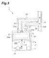
Fig. 3 is a conceptual diagram of a fuel cell system according to a second embodiment of the present invention. -
Fig. 4 is a conceptual diagram of a modification of the fuel cell system according to the second embodiment of the present invention. -
Fig. 5 is a conceptual diagram of a fuel cell system according to a third embodiment of the present invention. -
Fig. 6 is a conceptual diagram of a fuel cell system according to a fourth embodiment of the present invention. - Hereinafter, preferred embodiments of the present invention will be described in detail with reference to the drawings. In the drawings, the same or corresponding portions will be denoted by the same reference numerals and redundant description thereof will not be provided.
- As shown in
Fig. 1 , afuel cell system 1 includes a desulfurizingunit 2, a vaporizingunit 3, ahydrogen generating unit 4, acell stack 5, an off-gas combusting unit 6, a hydrogen-containingfuel supply unit 7, awater supply unit 8, anoxidant supply unit 9, apower conditioner 10, and acontrol unit 11. In thefuel cell system 1, thecell stack 5 performs power generation using hydrogen-containing fuel and oxidant. The type of thecell stack 5 in thefuel cell system 1 is not particularly limited, and for example, a polymer electrolyte fuel cell (PEFC), a solid oxide fuel cell (SOFC), a phosphoric acid fuel cell (PAFC), a molten carbonate fuel cell (MCFC), and other types of fuel cells can be used. The constituent components shown inFig. 1 may be appropriately omitted depending on the type of thecell stack 5, the type of hydrogen-containing fuel, a reforming method, and the like. - As the hydrogen-containing fuel, hydrocarbon-based fuel is used, for example. As the hydrocarbon-based fuel, compounds containing carbon and hydrogen (the compounds may contain other elements such as oxygen) in their molecules and mixtures thereof are used. Examples of the hydrocarbon-based fuel include hydrocarbons, alcohols, ethers, and biofuel, and hydrocarbon-based fuels that originate from existing fossil fuels such as petroleum or coal, that originate from synthetic fuels such as synthetic gas, and that originate from biomass can be appropriately used. Specifically, examples of hydrocarbons include methane, ethane, propane, butane, natural gas, liquefied petroleum gas (LPG), city gas, town gas, gasoline, naphtha, kerosene, and gas oil. Examples of alcohols include methanol and ethanol. Examples of ethers include dimethyl ether. Examples of biofuel include biogas, bioethanol, biodiesel, and bio jet.
- As the oxidant, air, pure oxygen gas (may contain impurities that are rarely removed by a general removal method), and oxygen-enriched air are used.
- The desulfurizing
unit 2 desulfurizes the hydrogen-containing fuel supplied to thehydrogen generating unit 4. The desulfurizingunit 2 has a desulfurizing catalyst for removing sulfurated compounds contained in the hydrogen-containing fuel. As a desulfurization method of the desulfurizingunit 2, an adsorptive desulfurization method of adsorbing and removing sulfurated compounds and a hydrodesulfurization method of allowing sulfurated compounds to react with hydrogen to remove the sulfurated compounds are used, for example. The desulfurizingunit 2 supplies the desulfurized hydrogen-containing fuel to thehydrogen generating unit 4. - The vaporizing
unit 3 generates steam supplied to thehydrogen generating unit 4 by heating and vaporizing water. When water is heated by the vaporizingunit 3, heat generated within thefuel cell system 1 such as heat of thehydrogen generating unit 4, heat of the off-gas combusting unit 6, or heat recovered from exhaust gas may be used. Moreover, water may be heated using additional heat sources such as a heater or a burner. Although only the heat supplied from the off-gas combusting unit 6 to thehydrogen generating unit 4 is illustrated as an example inFig. 1 , the present invention is not limited to this. The vaporizingunit 3 supplies the generated steam to thehydrogen generating unit 4. - The
hydrogen generating unit 4 generates hydrogen-rich gas using the hydrogen-containing fuel from the desulfurizingunit 2. The hydrogen generatingunit 4 has a reformer that reforms the hydrogen-containing fuel using a reforming catalyst. A reforming method used in thehydrogen generating unit 4 is not particularly limited, and for example, steam reforming, partial oxidation reforming, autothermal reforming, and other reforming methods can be used. Thehydrogen generating unit 4 may include a configuration for adjusting properties in addition to the reformer that reforms the hydrogen-containing fuel using the reforming catalyst depending on the properties of the hydrogen-rich gas required for thecell stack 5. For example, when the type of thecell stack 5 is a polymer electrolyte fuel cell (PEFC) or a phosphoric acid fuel cell (PAFC), thehydrogen generating unit 4 includes a configuration (for example, a shift reactor and a selective oxidation reactor) for removing carbon monoxides in the hydrogen-rich gas. Thehydrogen generating unit 4 supplies the hydrogen-rich gas to ananode 12 of thecell stack 5. - The
cell stack 5 performs power generation using the hydrogen-rich gas from thehydrogen generating unit 4 and the oxidant from theoxidant supply unit 9. Thecell stack 5 includes theanode 12 to which the hydrogen-rich gas is supplied, acathode 13 to which the oxidant is supplied, and anelectrolyte 14 disposed between theanode 12 and thecathode 13. The cell stack 5 supplies electric power to the outside via thepower conditioner 10. Thecell stack 5 supplies hydrogen-rich gas and oxidant that were not used for power generation to the off-gas combusting unit 6 as off-gas. A combusting unit (for example, a combustor or the like that heats the reformer) included in thehydrogen generating unit 4 may be used as the off-gas combusting unit 6. - The off-
gas combusting unit 6 combusts the off-gas supplied from thecell stack 5. The heat generated by the off-gas combusting unit 6 is supplied to thehydrogen generating unit 4 and is used for generation of the hydrogen-rich gas in thehydrogen generating unit 4. - The hydrogen-containing
fuel supply unit 7 supplies the hydrogen-containing fuel to thedesulfurizing unit 2. Thewater supply unit 8 supplies water to thevaporizing unit 3. Theoxidant supply unit 9 supplies the oxidant to thecathode 13 of thecell stack 5. The hydrogen-containingfuel supply unit 7, thewater supply unit 8, and theoxidant supply unit 9 are configured as a pump, for example, and are driven based on a control signal from thecontrol unit 11. - The
power conditioner 10 adjusts the electric power from thecell stack 5 according to a power consumption state on the outside. Thepower conditioner 10 performs a process of converting a voltage and a process of converting a DC power into an AC power, for example. - When hydrogen-containing fuel (for example, pure hydrogen gas, hydrogen-enriched gas, and the like) that does not require a reforming treatment is supplied by the hydrogen-containing
fuel supply unit 7, one or a plurality of thedesulfurizing unit 2, thewater supply unit 8, the vaporizingunit 3, and thehydrogen generating unit 4 may not be provided. - The
control unit 11 performs a process of controlling the entirefuel cell system 1. Thecontrol unit 11 is configured as a device that includes a central processing unit (CPU), a read only memory (ROM), a random access memory (RAM), and an input/output interface. Thecontrol unit 11 is electrically connected to the hydrogen-containingfuel supply unit 7, thewater supply unit 8, theoxidant supply unit 9, thepower conditioner 10, and other sensors and auxiliary devices (not shown). Thecontrol unit 11 gets various signals generated within thefuel cell system 1 and outputs a control signal to respective devices in thefuel cell system 1. - As shown in
Fig. 2 , thefuel cell system 1 includes ahousing 21 having air-tightness with respect to outside air. Thehousing 21 accommodates the above-described devices including thepower generating unit 22. Thepower generating unit 22 is a module that includes thecell stack 5 that generates power by using the hydrogen-rich gas (hydrogen-containing gas). Thepower generating unit 22 includes at least thecell stack 5 and may further include the off-gas combusting unit 6, thehydrogen generating unit 4, and the like, and may not include the off-gas combusting unit 6, thehydrogen generating unit 4, and the like. - An
air introduction path 23 is connected to thehousing 21. Theair introduction path 23 is used for introducing air to be supplied to thecathode 13 of thecell stack 5, from the outside of thehousing 21 to the inside of thehousing 21. Adownstream end 23a of theair introduction path 23 is connected to an upper portion (in this example, an upper wall of the housing 21) of thehousing 21 so as to directly face thepower generating unit 22. - An
air flow path 24 that includesair flow paths housing 21. Theair flow path 24a is formed on an upper side of apartitioning member 21a in thehousing 21 so as to surround thepower generating unit 22. Theair flow path 24b is formed on a lower side of the partitioningmember 21 a in thehousing 21 so as to be located downstream of theair flow path 24a. Theair flow path 24 is used for causing air introduced into thehousing 21 through theair introduction path 23 to flow in thehousing 21 to thereby transfer heat from thepower generating unit 22 to the air to cool thepower generating unit 22. - Further, a
blower 25 that corresponds to theoxidant supply unit 9 described above is accommodated in thehousing 21. Theblower 25 is provided downstream of theair flow path 24b so as to supply the air introduced into thehousing 21 through theair introduction path 23 to thecathode 13 of thecell stack 5. The air to be supplied to thecathode 13 by theblower 25 flows anair supply path 29 that is provided downstream from theblower 25. The flow of air in theair introduction path 23, theair flow path 24, and theair supply path 29 is generated by theblower 25. - The combustion gas (that is, the exhaust gas from the off-gas combusting unit 6) of the off-gas discharged from the
cell stack 5 is discharged outside thehousing 21 through the combustiongas discharge path 28. The combustiongas discharge path 28 flows through theair introduction path 23, and the combustiongas discharge path 28 and theair introduction path 23 form a duplex pipe. - As described above, in the
fuel cell system 1, air is introduced from the outside of thehousing 21 to the inside of thehousing 21 through theair introduction path 23. In this case, thedownstream end 23a of theair introduction path 23 is connected to thehousing 21 so as to directly face thepower generating unit 22. That is, thedownstream end 23a of theair introduction path 23 is connected to thehousing 21 so that thepower generating unit 22 is positioned on a central line of an opening of thedownstream end 23a. Thus, the air introduced into thehousing 21 is first blown to thepower generating unit 22, and thepower generating unit 22 is cooled. In this case, since thedownstream end 23a of theair introduction path 23 is connected to the upper portion of thehousing 21 so as to directly face thepower generating unit 22, it is possible to effectively cool thepower generating unit 22. In thehousing 21, the heat is transferred from thepower generating unit 22 to the air flowing in theair flow path 24, and thepower generating unit 22 is further cooled. Further, the flow of the air in theair introduction path 23, theair flow path 24, and theair supply path 29 is generated by theblower 25 that supplies air to thecathode 13 of the cell stack 5 (that is, it is not necessary to provide an additional auxiliary device or the like for generating the flow of air). Thus, according to thefuel cell system 1, it is possible to efficiently cool thepower generating unit 22 that is accommodated in thehousing 21 having air-tightness (such properties that thehousing 21 is tightly sealed against outside air other than gas that is to be introduced into the housing 21 (air or the like introduced from the outside of thehousing 21 to the inside of thehousing 21 through the air introduction path 23)). On the other hand, since air is heated in theair flow path 24, the heated air is supplied to thecathode 13 of thecell stack 5 so that the power generation efficiency of thecell stack 5 can be improved. - Moreover, even if the
blower 25 is stopped due to a certain reason, since thedownstream end 23a of theair introduction path 23 is connected to the upper portion of thehousing 21, hot air can be easily introduced into theair introduction path 23. In this manner, it is possible to smoothly and reliably discharge hot air from the inside of thehousing 21 to the outside of thehousing 21 through theair introduction path 23. - As shown in
Fig. 3 , thefuel cell system 1 according to the second embodiment is mainly different from thefuel cell system 1 according to the first embodiment in that a firstair discharge path 26 is provided. In thefuel cell system 1 according to the second embodiment, the firstair discharge path 26 is connected to thehousing 21. Anupstream end 26a of the firstair discharge path 26 is connected to an upper portion (in this example, an upper wall of the housing 21) of thehousing 21. On the other hand, adownstream end 26b of the firstair discharge path 26 is connected halfway to the combustiongas discharge path 28. In this manner, the air flowing in the firstair discharge path 26 flows into the combustiongas discharge path 28. - A first opening/closing unit 27 (for example, an electromagnetic valve) that opens and closes the first
air discharge path 26 is attached to the firstair discharge path 26. The first opening/closing unit 27 is controlled by the control unit 11 (alternatively, an external control unit) so that the firstair discharge path 26 is closed when theblower 25 operates and that the firstair discharge path 26 is opened when theblower 25 is stopped due to a certain reason. Moreover, when the firstair discharge path 26 is opened by the first opening/closing unit 27, the air introduced from the outside of thehousing 21 to the inside of thehousing 21 through theair introduction path 23 is discharged from the inside of thehousing 21 to the outside of thehousing 21 through the firstair discharge path 26. - In this manner, the first opening/
closing unit 27 closes the firstair discharge path 26 when theblower 25 operates, and the first opening/closing unit 27 opens the firstair discharge path 26 when theblower 25 is stopped due to a certain reason. Thus, in a fuel cell system where a portion of theair introduction path 23 is shared by another device and sucking force of the other device is strong, and in a fuel cell system where a backflow prevention valve is attached to theair introduction path 23, it is possible to reliably discharge hot air from the inside of thehousing 21 to the outside of thehousing 21 through the firstair discharge path 26 during emergency stop of theblower 25 and emergency stop of thefuel cell system 1. - Moreover, since the
upstream end 26a of the firstair discharge path 26 is connected to the upper portion of thehousing 21, when the first opening/closing unit 27 opens the firstair discharge path 26, hot air can be easily introduced into the firstair discharge path 26. In this manner, it is possible to smoothly and reliably discharge hot air through the firstair discharge path 26 when the first opening/closing unit 27 opens the firstair discharge path 26. - As shown in
Fig. 4 , thedownstream end 23a of theair introduction path 23 may be connected to a side portion (in this example, a side wall of the housing 21) of thehousing 21 if thedownstream end 23a directly faces thepower generating unit 22. In this case, theblower 25 is provided downstream of theair flow path 24b, and supplies the air introduced into thehousing 21 through theair introduction path 23 to thecathode 13 of thecell stack 5. - As shown in
Fig. 5 , thefuel cell system 1 according to the third embodiment is mainly different from thefuel cell system 1 according to the second embodiment in that a secondair discharge path 30 is provided in addition to the firstair discharge path 26. In thefuel cell system 1 according to the third embodiment, a flow path formed downstream from theblower 25 branches into anair supply path 29 and a secondair discharge path 30. The secondair discharge path 30 has adownstream end 30b connected to the combustiongas discharge path 28 so as to communicate with the combustiongas discharge path 28. In this manner, the air flowing in the secondair discharge path 30 flows into the combustiongas discharge path 28. The secondair discharge path 30 may have thedownstream end 30b connected to a portion of the firstair discharge path 26 located downstream from the first opening/closing unit 27 so as to communicate with the combustiongas discharge path 28. - In this manner, air required for power generation among the air introduced into the
housing 21 by theblower 25 is supplied to thepower generating unit 22, and surplus air is discharged to the outside through the secondair discharge path 30. Thus, since the amount of air introduced into thehousing 21 from theair introduction path 23 is not limited to the amount of air provided for power generation, it is possible to effectively cool the inside of thehousing 21. Moreover, since the surplus air in thehousing 21 is discharged to the outside through the secondair discharge path 30, it is possible to suppress an excessive increase in the pressure inside thehousing 21 even if thehousing 21 that accommodates thepower generating unit 22 has air-tightness. - As shown in
Fig. 6 , thefuel cell system 1 according to the fourth embodiment is mainly different from thefuel cell system 1 according to the third embodiment, in that a second opening/closing unit 31 (for example, an electromagnetic valve) and atemperature measuring unit 32 are provided. In thefuel cell system 1 according to the fourth embodiment, the secondair discharge path 30 has adownstream end 30b connected to a portion of the firstair discharge path 26 located downstream from the first opening/closing unit 27 so as to communicate with the combustiongas discharge path 28. In this manner, the air flowing in the secondair discharge path 30 flows into the combustiongas discharge path 28. The secondair discharge path 30 may have thedownstream end 30b connected to the combustiongas discharge path 28 so as to communicate with the combustiongas discharge path 28. - The
temperature measuring unit 32 measures the temperature inside thehousing 21. The second opening/closing unit 31 is provided in the secondair discharge path 30 so as to open and close the secondair discharge path 30. Thecontrol unit 11 gets the temperature inside thehousing 21 measured by thetemperature measuring unit 32. Moreover, when the temperature gotten from thetemperature measuring unit 32 exceeds a predetermined temperature, thecontrol unit 11 controls theblower 25 so that the amount of air introduced into thehousing 21 is increased to be larger than the amount of air required for power generation and also controls the second opening/closing unit 31 so that the secondair discharge path 30 is opened. On the other hand, when the temperature gotten from thetemperature measuring unit 32 is equal to or lower than the predetermined temperature, thecontrol unit 11 controls theblower 25 so that the amount of air introduced into thehousing 21 is equal to the amount of air required for power generation and also controls the second opening/closing unit 31 so that the secondair discharge path 30 is closed. - In this manner, the amount of air introduced into the
housing 21 by theblower 25 is increased only when the temperature inside thehousing 21 exceeds the predetermined temperature, whereby the surplus air in thehousing 21 can be discharged to the outside through the secondair discharge path 30. Moreover, when the temperature inside thehousing 21 is equal to or lower than the predetermined temperature, the air heated by thepower generating unit 22 is supplied as the cathode air of thepower generating unit 22, whereby a decrease in the power generation efficiency of thefuel cell system 1 can be suppressed. - The
temperature measuring unit 32 may be provided at an optional place if it is inside thehousing 21. For example, thetemperature measuring unit 32 may be provided on an upper surface of thepower generating unit 22 where hot air is likely to gather or near thepower conditioner 10 which is relatively easily influenced by an ambient temperature among the auxiliary devices that constitute thefuel cell system 1. - While an embodiment of the present invention has been described, the present invention is not limited to the above embodiment. For example, the
housing 21 may not have air-tightness. In this case, since it is not necessary to provide, in thehousing 21, additional means such as a fan, for introducing air from the outside of thehousing 21 to the inside of thehousing 21, it is possible to simplify the structure of thefuel cell system 1. - Moreover, in the
fuel cell system 1 shown inFigs. 2 ,4 ,5 , and6 , although the combustiongas discharge path 28 and theair introduction path 23 form a duplex pipe, the combustiongas discharge path 28 and theair introduction path 23 may be provided separately as shown inFig. 3 . - That is, the present invention is not limited to a fuel cell system having a configuration in which the combustion
gas discharge path 28 flows through theair introduction path 23, the combustiongas discharge path 28 and theair introduction path 23 form a duplex pipe, and the downstream end of theair introduction path 23 and the upstream end of the combustiongas discharge path 28 are connected to the upper portion of thehousing 21. - Specifically, as shown in
Fig. 3 , the present invention can be applied to a fuel cell system having a configuration in which the combustiongas discharge path 28 and theair introduction path 23 do not form a duplex pipe but are provided separately. Moreover, as shown inFig. 4 , the present invention can be applied to a fuel cell system having a configuration in which the downstream end of theair introduction path 23 and the upstream end of the combustiongas discharge path 28 are connected to a side portion of thehousing 21. - Moreover, in the third and fourth embodiments, a flow meter may be provided on the
air supply path 29, and the amount of cathode air may be adjusted by controlling theblower 25 in a feedback manner. Further, output map data determined based on an air distribution ratio between theair supply path 29 and the secondair discharge path 30 may be stored in thecontrol unit 11, and the cathode air flow rate may be adjusted by controlling theblower 25 based on the data. Furthermore, theair supply path 29 and the secondair discharge path 30 may branch off from theblower 25 as shown inFig. 5 , and one path may branch off from the other path as shown inFig. 6 . The second opening/closing unit 31 in the fourth embodiment is not limited to an opening/closing unit which is completely opened or closed, but the degree of opening may be set in multiple steps. - According to the present invention, it is possible to efficiently cool the power generating unit accommodated in the housing.
-
- 1:
- fuel cell system
- 5:
- cell stack
- 13:
- cathode
- 21:
- housing
- 22:
- power generating unit
- 23:
- air introduction path
- 23a:
- downstream end
- 24, 24a, 24b:
- air flow path
- 25:
- blower
- 26:
- first air discharge path
- 26a:
- upstream end
- 27:
- first opening/closing unit
- 28:
- combustion gas discharge path
- 29:
- air supply path
- 30:
- second air discharge path
- 31:
- second opening/closing unit
- 32:
- temperature measuring unit
Claims (8)
- A fuel cell system comprising:a power generating unit including a cell stack for performing power generation by using hydrogen-containing gas;a housing for accommodating the power generating unit;an air introduction path for introducing air to be supplied to a cathode of the cell stack, from an outside of the housing to an inside of the housing;an air flow path for causing the air introduced to the inside of the housing through the air introduction path to flow in the inside of the housing, and to transfer heat from the power generating unit to the air so as to cool the power generating unit;a blower provided downstream of the air flow path so as to supply the air to the cathode; andan air supply path provided downstream from the blower so as to cause the air to be supplied to the cathode by the blower to flow.
- The fuel cell system according to claim 1, wherein
a downstream end of the air introduction path is connected to the housing so as to directly face the power generating unit. - The fuel cell system according to claim 1 or 2, further comprising:a combustion gas discharge path for discharging combustion gas discharged from the power generating unit;a first air discharge path for discharging the air introduced to the inside of the housing through the air introduction path, from the inside of the housing to the outside of the housing;a first opening/closing unit provided in the first air discharge path so as to open and close the first air discharge path; anda control unit for controlling the first opening/closing unit, whereinthe air flowing in the first air discharge path flows into the combustion gas discharge path.
- The fuel cell system according to claim 3, wherein
the control unit controls the first opening/closing unit so that the first air discharge path is opened when the blower is stopped. - The fuel cell system according to claim 3 or 4, wherein
an upstream end of the first air discharge path is connected to an upper portion of the housing. - The fuel cell system according to any one of claims 3 to 5, further comprising:a second air discharge path provided downstream from the blower so as to discharge the air introduced to the inside of the housing through the air introduction path, from the inside of the housing to the outside of the housing, whereinthe air flowing in the second air discharge path flows into the combustion gas discharge path.
- The fuel cell system according to claim 6, wherein
a downstream end of the second air discharge path is connected to the first air discharge path downstream from the first opening/closing unit. - The fuel cell system according to claim 6 or 7, further comprising:a temperature measuring unit for measuring a temperature of the inside of the housing; anda second opening/closing unit provided in the second air discharge path so as to open and close the second air discharge path, whereinwhen the temperature of the inside of the housing measured by the temperature measuring unit exceeds a predetermined temperature, the control unit controls the second opening/closing unit so that the second air discharge path is opened and also controls the blower so that an amount of the air to be introduced to the inside of the housing increases.
Applications Claiming Priority (2)
| Application Number | Priority Date | Filing Date | Title |
|---|---|---|---|
| JP2010292362 | 2010-12-28 | ||
| PCT/JP2011/080261 WO2012091031A1 (en) | 2010-12-28 | 2011-12-27 | Fuel cell system |
Publications (1)
| Publication Number | Publication Date |
|---|---|
| EP2660914A1 true EP2660914A1 (en) | 2013-11-06 |
Family
ID=46383122
Family Applications (1)
| Application Number | Title | Priority Date | Filing Date |
|---|---|---|---|
| EP11853595.4A Withdrawn EP2660914A1 (en) | 2010-12-28 | 2011-12-27 | Fuel cell system |
Country Status (4)
| Country | Link |
|---|---|
| EP (1) | EP2660914A1 (en) |
| JP (1) | JP5852011B2 (en) |
| KR (1) | KR20130133806A (en) |
| WO (1) | WO2012091031A1 (en) |
Cited By (4)
| Publication number | Priority date | Publication date | Assignee | Title |
|---|---|---|---|---|
| EP2963725A1 (en) * | 2014-06-30 | 2016-01-06 | Aisin Seiki Kabushiki Kaisha | Fuel cell system |
| EP2991149A1 (en) | 2014-08-27 | 2016-03-02 | Vaillant GmbH | Hot box of a fuel cell system |
| EP3503275A1 (en) * | 2017-12-21 | 2019-06-26 | Panasonic Intellectual Property Management Co., Ltd. | Fuel cell system |
| AT521878A1 (en) * | 2019-02-22 | 2020-05-15 | Avl List Gmbh | Fuel cell system, motor vehicle and method for cooling a fuel cell system |
Families Citing this family (3)
| Publication number | Priority date | Publication date | Assignee | Title |
|---|---|---|---|---|
| EP3086394B1 (en) * | 2013-12-18 | 2018-05-16 | Panasonic Intellectual Property Management Co., Ltd. | Power generation system |
| US9698438B2 (en) | 2014-09-18 | 2017-07-04 | Hyundai Motor Company | Ventilation apparatus and control method thereof |
| JP2020087533A (en) * | 2018-11-16 | 2020-06-04 | 株式会社Ihi | Fuel cell system |
Family Cites Families (9)
| Publication number | Priority date | Publication date | Assignee | Title |
|---|---|---|---|---|
| JP2006073446A (en) * | 2004-09-06 | 2006-03-16 | Fuji Electric Holdings Co Ltd | Fuel cell power generating device |
| JP2006156116A (en) * | 2004-11-29 | 2006-06-15 | Ebara Corp | Emergency fuel-cell power-generation apparatus and management method for the same |
| JP4981289B2 (en) * | 2005-09-29 | 2012-07-18 | 京セラ株式会社 | Fuel cell exhaust system |
| JP4932265B2 (en) | 2006-01-30 | 2012-05-16 | 京セラ株式会社 | Fuel cell system |
| JP4986587B2 (en) * | 2006-11-28 | 2012-07-25 | 京セラ株式会社 | Fuel cell device |
| JP5063126B2 (en) * | 2007-02-01 | 2012-10-31 | 京セラ株式会社 | Fuel cell device |
| JP5201849B2 (en) * | 2007-02-26 | 2013-06-05 | 京セラ株式会社 | Power generator |
| JP5201848B2 (en) * | 2007-02-26 | 2013-06-05 | 京セラ株式会社 | Fuel cell device |
| JP2008243591A (en) * | 2007-03-27 | 2008-10-09 | Kyocera Corp | Fuel cell device |
-
2011
- 2011-12-27 EP EP11853595.4A patent/EP2660914A1/en not_active Withdrawn
- 2011-12-27 JP JP2012550992A patent/JP5852011B2/en not_active Expired - Fee Related
- 2011-12-27 WO PCT/JP2011/080261 patent/WO2012091031A1/en active Application Filing
- 2011-12-27 KR KR1020137017812A patent/KR20130133806A/en not_active Application Discontinuation
Cited By (5)
| Publication number | Priority date | Publication date | Assignee | Title |
|---|---|---|---|---|
| EP2963725A1 (en) * | 2014-06-30 | 2016-01-06 | Aisin Seiki Kabushiki Kaisha | Fuel cell system |
| EP2991149A1 (en) | 2014-08-27 | 2016-03-02 | Vaillant GmbH | Hot box of a fuel cell system |
| DE102014217020A1 (en) | 2014-08-27 | 2016-03-03 | Vaillant Gmbh | Hotbox of a fuel cell system |
| EP3503275A1 (en) * | 2017-12-21 | 2019-06-26 | Panasonic Intellectual Property Management Co., Ltd. | Fuel cell system |
| AT521878A1 (en) * | 2019-02-22 | 2020-05-15 | Avl List Gmbh | Fuel cell system, motor vehicle and method for cooling a fuel cell system |
Also Published As
| Publication number | Publication date |
|---|---|
| JPWO2012091031A1 (en) | 2014-06-05 |
| KR20130133806A (en) | 2013-12-09 |
| WO2012091031A1 (en) | 2012-07-05 |
| JP5852011B2 (en) | 2016-02-03 |
Similar Documents
| Publication | Publication Date | Title |
|---|---|---|
| EP2660914A1 (en) | Fuel cell system | |
| EP2278650B1 (en) | Method for operating indirect internal reforming solid oxide fuel cell system | |
| US8927166B2 (en) | Indirect internal reforming solid oxide fuel cell and method for shutting down the same | |
| JP5255230B2 (en) | Fuel cell system | |
| US8771888B2 (en) | Fuel cell system and method of load following operation of the same | |
| JP2009004346A (en) | Reformer, fuel cell system, and shut-down method for reformer | |
| US20130143136A1 (en) | Hydrogen generation apparatus and fuel cell system | |
| US20130316257A1 (en) | Fuel cell system | |
| JP6114197B2 (en) | Fuel cell system | |
| WO2012091121A1 (en) | Fuel cell system | |
| EP2267827A1 (en) | Fuel cell system and method of load following operation of the same | |
| WO2012091029A1 (en) | Fuel cell system | |
| WO2012161217A1 (en) | Fuel cell system | |
| JP5782458B2 (en) | Fuel cell system | |
| JP2016143586A (en) | Fuel battery system and method of stopping the same | |
| JPWO2012091120A1 (en) | Fuel cell system | |
| WO2011001909A1 (en) | Method for load follow-up operation of fuel cell system | |
| JP2017016816A (en) | Fuel cell system, stop method for fuel cell system, and power production method | |
| JP5728497B2 (en) | Fuel cell system | |
| AU2014365865B2 (en) | Gas circuit for a solid oxide fuel cell system and a solid oxide fuel cell system | |
| KR101358132B1 (en) | Fuel exhausting system for ship | |
| JP5400425B2 (en) | Hydrogen production apparatus and fuel cell system | |
| WO2012090964A1 (en) | Fuel cell system | |
| KR20120051067A (en) | Load following operation method for fuel cell system | |
| JP2016119151A (en) | Fuel cell system and operation method of fuel cell system |
Legal Events
| Date | Code | Title | Description |
|---|---|---|---|
| PUAI | Public reference made under article 153(3) epc to a published international application that has entered the european phase |
Free format text: ORIGINAL CODE: 0009012 |
|
| 17P | Request for examination filed |
Effective date: 20130725 |
|
| AK | Designated contracting states |
Kind code of ref document: A1 Designated state(s): AL AT BE BG CH CY CZ DE DK EE ES FI FR GB GR HR HU IE IS IT LI LT LU LV MC MK MT NL NO PL PT RO RS SE SI SK SM TR |
|
| DAX | Request for extension of the european patent (deleted) | ||
| STAA | Information on the status of an ep patent application or granted ep patent |
Free format text: STATUS: THE APPLICATION HAS BEEN WITHDRAWN |
|
| 18W | Application withdrawn |
Effective date: 20150811 |