JP2017016816A - Fuel cell system, stop method for fuel cell system, and power production method - Google Patents

Fuel cell system, stop method for fuel cell system, and power production method Download PDF

Info

Publication number
JP2017016816A
JP2017016816A JP2015130683A JP2015130683A JP2017016816A JP 2017016816 A JP2017016816 A JP 2017016816A JP 2015130683 A JP2015130683 A JP 2015130683A JP 2015130683 A JP2015130683 A JP 2015130683A JP 2017016816 A JP2017016816 A JP 2017016816A
Authority
JP
Japan
Prior art keywords
fuel cell
anode
oxidant gas
temperature
reforming
Prior art date
Legal status (The legal status is an assumption and is not a legal conclusion. Google has not performed a legal analysis and makes no representation as to the accuracy of the status listed.)
Pending
Application number
JP2015130683A
Other languages
Japanese (ja)
Inventor
安美 山口
Yasumi Yamaguchi
安美 山口
Current Assignee (The listed assignees may be inaccurate. Google has not performed a legal analysis and makes no representation or warranty as to the accuracy of the list.)
Eneos Corp
Original Assignee
JX Nippon Oil and Energy Corp
Priority date (The priority date is an assumption and is not a legal conclusion. Google has not performed a legal analysis and makes no representation as to the accuracy of the date listed.)
Filing date
Publication date
Application filed by JX Nippon Oil and Energy Corp filed Critical JX Nippon Oil and Energy Corp
Priority to JP2015130683A priority Critical patent/JP2017016816A/en
Publication of JP2017016816A publication Critical patent/JP2017016816A/en
Pending legal-status Critical Current

Links

Images

Classifications

    • YGENERAL TAGGING OF NEW TECHNOLOGICAL DEVELOPMENTS; GENERAL TAGGING OF CROSS-SECTIONAL TECHNOLOGIES SPANNING OVER SEVERAL SECTIONS OF THE IPC; TECHNICAL SUBJECTS COVERED BY FORMER USPC CROSS-REFERENCE ART COLLECTIONS [XRACs] AND DIGESTS
    • Y02TECHNOLOGIES OR APPLICATIONS FOR MITIGATION OR ADAPTATION AGAINST CLIMATE CHANGE
    • Y02EREDUCTION OF GREENHOUSE GAS [GHG] EMISSIONS, RELATED TO ENERGY GENERATION, TRANSMISSION OR DISTRIBUTION
    • Y02E60/00Enabling technologies; Technologies with a potential or indirect contribution to GHG emissions mitigation
    • Y02E60/30Hydrogen technology
    • Y02E60/50Fuel cells

Abstract

PROBLEM TO BE SOLVED: To provide a fuel cell system which shortens the time required for temperature fall while suppressing oxidation of a device during operation stop, a stop method for the fuel cell system and a power production method.SOLUTION: A fuel cell system 1 comprises: a modification part 11; a raw material supply part 16; a modified water supply part 13; a fuel cell 20 including an anode 21 and a cathode 22; an oxidant gas supply part 28; an anode temperature detector 25; and a control part 90. The control part 90 controls the raw material supply part 16, the modified water supply part 13 and the oxidant gas supply part 28 in such a manner that a reduction mixed fluid R for which a raw material D at a flow rate lower than that in power generation is mixed with modified water W, is supplied through the modification part 11 to the anode 21 while continuing supply of an oxidant gas A to the cathode 22 after power generation stop of the fuel cell 20, and that the oxidant gas A is then supplied to the anode 21 by the oxidant gas supply part 28 when a temperature detected by the anode temperature detector 25 becomes a first predetermined temperature after supply stop of the reduction mixed fluid R.SELECTED DRAWING: Figure 1

Description

本発明は燃料電池システム、燃料電池システムの停止方法及び電力生産方法に関し、特に、運転停止時に、装置の酸化を抑制降温に要する時間を短縮する燃料電池システム、燃料電池システムの停止方法及び電力生産方法に関する。   The present invention relates to a fuel cell system, a fuel cell system stop method, and a power production method, and in particular, a fuel cell system that suppresses oxidation of the apparatus and reduces a time required for temperature reduction when the operation is stopped, a fuel cell system stop method, and power production. Regarding the method.

水素含有ガスと酸素含有ガスとを導入して発電する燃料電池を設置する際、炭化水素系原料を改質して水素含有ガスとする改質器が併設されることが多い。炭化水素系原料を改質する方式の1つとして、炭化水素系原料に水蒸気を混合し加熱して改質する水蒸気改質がある。燃料電池及び改質器は、運転中に高温(一般に700℃以上)になる。運転中に高温となっている燃料電池及び改質器の運転を停止する際、改質器内や燃料電池内に不活性ガスを流すことで、燃料電池内の電極や改質器内の触媒等の酸化を抑制しつつ、高温から室温付近まで降温させるのに要する時間を短縮することが行われている。さらに、不活性ガスの供給設備を不要とするために、燃料電池内への空気の供給を継続して行いながら、炭化水素ガスの供給量を低減させ、低減された量の炭化水素ガスと水蒸気との混合ガスを改質器を通して燃料電池内に供給し、改質触媒の温度が該触媒の酸化発生温度±150℃の範囲に降温したときに、混合ガスの供給を停止し、該混合ガスの供給を停止した後に、空気又は炭化水素ガスをパージガスとして改質器を通して燃料電池に流してパージするものがある(例えば、特許文献1参照)。   When installing a fuel cell that introduces a hydrogen-containing gas and an oxygen-containing gas to generate power, a reformer is often provided along with reforming a hydrocarbon-based raw material into a hydrogen-containing gas. One of the methods for reforming a hydrocarbon-based material is steam reforming in which steam is mixed with a hydrocarbon-based material and heated to reform. Fuel cells and reformers become hot (generally 700 ° C. or higher) during operation. When stopping the operation of the fuel cell and reformer that are at high temperature during operation, an inert gas is allowed to flow in the reformer and the fuel cell, so that the electrode in the fuel cell and the catalyst in the reformer The time required to lower the temperature from high temperature to near room temperature is reduced while suppressing oxidation such as the above. Furthermore, in order to eliminate the need for an inert gas supply facility, the supply amount of hydrocarbon gas is reduced while continuing the supply of air into the fuel cell, and the reduced amount of hydrocarbon gas and water vapor is reduced. Gas is supplied into the fuel cell through the reformer, and the supply of the mixed gas is stopped when the temperature of the reforming catalyst falls within the range of the oxidation occurrence temperature of the catalyst ± 150 ° C. After the supply of the gas is stopped, air or hydrocarbon gas is purged as a purge gas through a reformer (see, for example, Patent Document 1).

特許第4906242号公報Japanese Patent No. 4906242

しかしながら、特許文献1に記載されている停止の手段では、パージガスとして空気を改質器に供給する際に、空気を供給する設備が別途必要になる。   However, the stopping means described in Patent Document 1 requires a separate facility for supplying air when supplying air as the purge gas to the reformer.

本発明は上述の課題に鑑み、簡便な構成で、運転停止時に、装置の酸化を抑制するようにガスを供給しながら装置の降温に要する時間を短縮する燃料電池システム、燃料電池システムの停止方法及び電力生産方法を提供することを目的とする。   In view of the above-described problems, the present invention provides a fuel cell system and a fuel cell system stopping method that reduce the time required for the temperature of the apparatus to be reduced while supplying gas so as to suppress oxidation of the apparatus when the operation is stopped, in a simple configuration. And it aims at providing the electric power production method.

上記目的を達成するために、本発明の第1の態様に係る燃料電池システムは、例えば図1に示すように、炭化水素系の原料Dと改質水Wとを導入し、原料Dを、水素を含有する改質ガスEに改質する改質部11と;原料Dを改質部11に供給する原料供給部16と;改質水Wを改質部11に供給する改質水供給部13と;改質部11で生成された改質ガスEを導入するアノード21と、酸素を含有する酸化剤ガスAとを導入するカソード22とを有し、発電する燃料電池20と;カソード22に酸化剤ガスAを供給する酸化剤ガス供給部28と;アノード21の温度又はアノード21の温度と相関を有する温度を直接又は間接的に検知するアノード温度検知器25と;燃料電池20の発電停止後、カソード22への酸化剤ガスAの供給を継続して行いつつ、燃料電池20の発電時に改質部11に供給されていた流量よりも少ない流量の原料Dが改質水Wと混合した減少混合流体Rを、改質部11を介してアノード21に供給して燃料電池20及び改質部11を冷却し、その後、改質部11及びアノード21への減少混合流体Rの供給停止以後のアノード温度検知器25で検知した温度が第1の所定の温度になったときに酸化剤ガス供給部28によって酸化剤ガスAをアノード21に供給するように、原料供給部16、改質水供給部13、酸化剤ガス供給部28を制御する制御部90とを備える。   In order to achieve the above object, the fuel cell system according to the first aspect of the present invention introduces a hydrocarbon-based raw material D and reformed water W, as shown in FIG. A reforming unit 11 for reforming the reformed gas E containing hydrogen; a raw material supply unit 16 for supplying the raw material D to the reforming unit 11; and a reforming water supply for supplying the reforming water W to the reforming unit 11 A fuel cell 20 for generating electricity, including an anode 21 for introducing the reformed gas E generated in the reforming unit 11 and a cathode 22 for introducing an oxidant gas A containing oxygen; An oxidant gas supply unit 28 for supplying the oxidant gas A to 22; an anode temperature detector 25 for directly or indirectly detecting the temperature of the anode 21 or a temperature correlated with the temperature of the anode 21; Continued supply of oxidant gas A to cathode 22 after power generation stopped The reduced mixed fluid R in which the raw material D having a flow rate smaller than the flow rate supplied to the reforming unit 11 during power generation of the fuel cell 20 is mixed with the reforming water W is supplied to the anode 21 via the reforming unit 11. To cool the fuel cell 20 and the reforming unit 11, and then the temperature detected by the anode temperature detector 25 after the supply of the reduced mixed fluid R to the reforming unit 11 and the anode 21 is stopped is the first predetermined value. The control part which controls the raw material supply part 16, the reforming water supply part 13, and the oxidant gas supply part 28 so that the oxidant gas A is supplied to the anode 21 by the oxidant gas supply part 28 when the temperature reaches 90.

このように構成すると、アノード温度検知器で検知した温度が第1の所定の温度になったときに、燃料電池の発電時に利用していた酸化剤ガス供給部を燃料電池停止後の冷却時にも用いて酸化剤ガスをアノードに供給するので、装置構成を簡略化しつつアノードの酸化を抑制することができる。   With this configuration, when the temperature detected by the anode temperature detector reaches the first predetermined temperature, the oxidant gas supply unit used at the time of power generation of the fuel cell is also cooled when the fuel cell is stopped. Since the oxidant gas is supplied to the anode, the oxidation of the anode can be suppressed while simplifying the device configuration.

また、本発明の第2の態様に係る燃料電池システムは、例えば図1を参照して示すと、上記本発明の第1の態様に係る燃料電池システム1において、制御部90は、アノード温度検知器25で検知した温度が第1の所定の温度になったときに、改質部11及びアノード21への減少混合流体Rの供給を停止すると共に酸化剤ガス供給部28によって酸化剤ガスAをアノード21に供給する。   In addition, the fuel cell system according to the second aspect of the present invention is shown, for example, with reference to FIG. 1. In the fuel cell system 1 according to the first aspect of the present invention, the control unit 90 detects the anode temperature. When the temperature detected by the vessel 25 reaches the first predetermined temperature, the supply of the reduced mixed fluid R to the reforming unit 11 and the anode 21 is stopped and the oxidizing gas A is supplied by the oxidizing gas supply unit 28. Supply to the anode 21.

このように構成すると、酸化剤ガスをアノードに供給する直前まで減少混合流体を改質部及びアノードに供給することとなり、改質部及びアノードの冷却を促進させることができる。   With this configuration, the reduced mixed fluid is supplied to the reforming unit and the anode until just before the oxidizing gas is supplied to the anode, and cooling of the reforming unit and the anode can be promoted.

また、本発明の第3の態様に係る燃料電池システムは、例えば図1に示すように、上記本発明の第1の態様に係る燃料電池システム1において、改質部11の温度又は改質部11の温度と相関を有する温度を直接又は間接的に検知する改質部温度検知器15を備え;制御部90は、改質部温度検知器15で検知した温度が第1の所定の温度よりも高い第2の所定の温度まで低下した時点で改質部11及びアノード21への減少混合流体Rの供給を停止する。   Further, the fuel cell system according to the third aspect of the present invention is, for example, as shown in FIG. 1, in the fuel cell system 1 according to the first aspect of the present invention, the temperature of the reforming section 11 or the reforming section. 11 includes a reforming unit temperature detector 15 that directly or indirectly detects a temperature having a correlation with the temperature of 11; the control unit 90 detects a temperature detected by the reforming unit temperature detector 15 from a first predetermined temperature. The supply of the reduced mixed fluid R to the reforming unit 11 and the anode 21 is stopped when the temperature is lowered to a higher second predetermined temperature.

このように構成すると、減少混合流体中の原料の改質が不十分な状態でアノードに導入されることを低減することができ、アノードが劣化するリスクを低減することができる。   If comprised in this way, it can reduce that the raw material in a reduction | decrease mixed fluid is introduce | transduced into an anode in the state which is insufficient, and can reduce the risk that an anode deteriorates.

また、本発明の第4の態様に係る燃料電池システムは、例えば図1に示すように、上記本発明の第1の態様乃至第3の態様のいずれか1つの態様に係る燃料電池システム1において、燃料電池20の発電時の改質ガスEの流れ方向におけるアノード21の上流側に設けられ、酸化剤ガス供給部28によってアノード21に供給された酸化剤ガスAを系外に排出する開閉弁75v及び/又は76vを備え;制御部90は、酸化剤ガス供給部28によって酸化剤ガスAがアノード21に供給されているときに開閉弁75v又は76vを開にするように、開閉弁75v又は76vを制御する。   Further, the fuel cell system according to the fourth aspect of the present invention is, for example, as shown in FIG. 1, in the fuel cell system 1 according to any one of the first to third aspects of the present invention. An on-off valve that is provided upstream of the anode 21 in the flow direction of the reformed gas E during power generation of the fuel cell 20 and discharges the oxidant gas A supplied to the anode 21 by the oxidant gas supply unit 28 to the outside of the system. 75v and / or 76v; the control unit 90 opens or closes the on-off valve 75v or 76v so that the on-off valve 75v or 76v is opened when the oxidant gas A is supplied to the anode 21 by the oxidant gas supply unit 28. 76v is controlled.

このように構成すると、簡便な構成でアノードに酸化剤ガスを流すことができ、アノードに残存する原料由来のガスをパージすることができる。   If comprised in this way, oxidant gas can be flowed to an anode by simple structure, and the gas derived from the raw material which remains on an anode can be purged.

また、本発明の第5の態様に係る燃料電池システムは、例えば図1を参照して示すと、上記本発明の第4の態様に係る燃料電池システム1において、制御部90は、酸化剤ガス供給部28によって酸化剤ガスAをアノード21に供給するときに、燃料電池20の発電時にカソード22に供給されていた流量よりも多い流量の酸化剤ガスAが酸化剤ガス供給部28から供給されるように、酸化剤ガス供給部28を制御する。   In addition, when the fuel cell system according to the fifth aspect of the present invention is shown, for example, with reference to FIG. 1, in the fuel cell system 1 according to the fourth aspect of the present invention, the control unit 90 includes an oxidant gas. When the oxidant gas A is supplied to the anode 21 by the supply unit 28, the oxidant gas A having a flow rate higher than that supplied to the cathode 22 during power generation of the fuel cell 20 is supplied from the oxidant gas supply unit 28. Thus, the oxidant gas supply unit 28 is controlled.

このように構成すると、比較的圧力損失が大きいアノードの系統に、より多い流量の酸化剤ガスをカソードから逆流させることができる。   With this configuration, a larger flow rate of oxidant gas can be caused to flow backward from the cathode into the anode system having a relatively large pressure loss.

また、本発明の第6の態様に係る燃料電池システムは、例えば図1を参照して示すと、上記本発明の第4の態様又は第5の態様に係る燃料電池システム1において、開閉弁76vが、改質部11とアノード21との間に設けられている。   The fuel cell system according to the sixth aspect of the present invention is, for example, referring to FIG. 1, the open / close valve 76v in the fuel cell system 1 according to the fourth aspect or the fifth aspect of the present invention. Is provided between the reforming section 11 and the anode 21.

このように構成すると、酸化剤ガス供給部によってアノードに供給された酸化剤ガスを、改質部を通さずに系外に排出することができ、改質部の酸化発生リスクのある温度の下限が燃料電池の酸化発生リスクのある温度の下限より低い場合に、改質部の酸化発生リスクを低減することができる。   With this configuration, the oxidant gas supplied to the anode by the oxidant gas supply unit can be discharged out of the system without passing through the reforming unit, and the lower limit of the temperature at which there is a risk of oxidation in the reforming unit. Is lower than the lower limit of the temperature at which there is a risk of oxidation of the fuel cell, the risk of occurrence of oxidation in the reforming section can be reduced.

また、本発明の第7の態様に係る燃料電池システムは、例えば図1を参照して示すと、上記本発明の第4の態様又は第5の態様に係る燃料電池システム1において、開閉弁75vが、燃料電池20の発電時の原料Dの流れ方向における改質部11の上流側に設けられている。   Further, the fuel cell system according to the seventh aspect of the present invention is, for example, referring to FIG. 1, the open / close valve 75v in the fuel cell system 1 according to the fourth aspect or the fifth aspect of the present invention. Is provided on the upstream side of the reforming unit 11 in the flow direction of the raw material D during power generation of the fuel cell 20.

このように構成すると、酸化剤ガス供給部によってアノードに供給された酸化剤ガスで改質部をもパージすることができる。   If comprised in this way, a modification part can also be purged with the oxidant gas supplied to the anode by the oxidant gas supply part.

また、本発明の第8の態様に係る燃料電池システムは、例えば図1に示すように、上記本発明の第4の態様乃至第7の態様のいずれか1つの態様に係る燃料電池システム1において、燃料電池20の発電時にカソード22に供給された酸化剤ガスAのうちの燃料電池20における発電に利用されなかったカソードオフガスFaをカソード22の外に排出するオフガスライン64と;オフガスライン64から系外に流体を排出する排出口65eまでの間に設けられた絞り流路64fとを備える。   Further, the fuel cell system according to the eighth aspect of the present invention is, for example, as shown in FIG. 1, in the fuel cell system 1 according to any one of the fourth to seventh aspects of the present invention. An off-gas line 64 that discharges the cathode off-gas Fa that has not been used for power generation in the fuel cell 20 out of the oxidant gas A supplied to the cathode 22 during power generation of the fuel cell 20; And a throttle channel 64f provided between the system and a discharge port 65e for discharging the fluid.

このように構成すると、燃料電池の発電の停止後に酸化剤ガス供給部によって酸化剤ガスがカソードに供給されつつアノードへの減少混合流体の供給を停止したときに、カソードに供給された酸化剤ガスをアノードに導きやすくすることができる。   With this configuration, when the supply of the reduced mixed fluid to the anode is stopped while the oxidant gas is supplied to the cathode by the oxidant gas supply unit after the power generation of the fuel cell is stopped, the oxidant gas supplied to the cathode Can be easily guided to the anode.

また、本発明の第9の態様に係る燃料電池システムは、例えば図1を参照して示すと、上記本発明の第4の態様乃至第7の態様のいずれか1つの態様に係る燃料電池システム1において、燃料電池20の発電時にカソード22に供給された酸化剤ガスAのうちの燃料電池20における発電に利用されなかったカソードオフガスFaをカソード22の外に排出するオフガスライン64と;オフガスライン64から系外に流体を排出する排出口65eまでの間に設けられ、開度を調節可能な開度調節装置とを備える。   In addition, the fuel cell system according to the ninth aspect of the present invention is, for example, referring to FIG. 1, and the fuel cell system according to any one of the fourth to seventh aspects of the present invention described above. 1, an offgas line 64 that discharges the cathode offgas Fa that is not used for power generation in the fuel cell 20 out of the oxidant gas A supplied to the cathode 22 during power generation of the fuel cell 20; And an opening degree adjusting device that is provided between 64 and a discharge port 65e that discharges fluid out of the system.

このように構成すると、開度調節装置の開度を、燃料電池の発電時に大きくし、酸化剤ガス供給部によって酸化剤ガスがアノードに供給されるときに小さくすることが可能となり、燃料電池システムの適切な運転及び停止が可能になる。   With this configuration, the opening degree of the opening degree adjusting device can be increased during power generation of the fuel cell, and can be reduced when the oxidant gas is supplied to the anode by the oxidant gas supply unit. Appropriate operation and shutdown of the system becomes possible.

また、本発明の第10の態様に係る燃料電池システムは、例えば図6に示すように、上記本発明の第1の態様乃至第3の態様のいずれか1つの態様に係る燃料電池システム1Aにおいて、酸化剤ガス供給部28から吐出された酸化剤ガスAをカソード22に導く酸化剤ガスライン62と;酸化剤ガスライン62とアノード21とを連絡するバイパスライン68とを備え;バイパスライン68は、流路を開閉可能なバイパス弁68vを有し;制御部90(例えば図1参照)は、酸化剤ガス供給部28によって酸化剤ガスAをアノード21に供給するときに、酸化剤ガス供給部28から吐出された酸化剤ガスAがバイパスライン68に流入するようにバイパス弁68vを制御する。   Further, a fuel cell system according to a tenth aspect of the present invention is a fuel cell system 1A according to any one of the first to third aspects of the present invention as shown in FIG. An oxidant gas line 62 that guides the oxidant gas A discharged from the oxidant gas supply unit 28 to the cathode 22; a bypass line 68 that connects the oxidant gas line 62 and the anode 21; The control unit 90 (see, for example, FIG. 1) includes an oxidant gas supply unit when the oxidant gas A is supplied to the anode 21 by the oxidant gas supply unit 28. The bypass valve 68v is controlled so that the oxidant gas A discharged from the gas 28 flows into the bypass line 68.

このように構成すると、酸化剤ガス供給部によってアノードに供給する酸化剤ガスの流れ方向を、燃料電池の発電時と同じにすることができ、アノードへの酸化剤ガスの供給を安定させることができる。   If comprised in this way, the flow direction of the oxidant gas supplied to an anode by an oxidant gas supply part can be made the same as the time of the power generation of a fuel cell, and supply of oxidant gas to an anode can be stabilized. it can.

また、本発明の第11の態様に係る燃料電池システムは、例えば図1を参照して示すと、上記本発明の第1の態様乃至第10の態様のいずれか1つの態様に係る燃料電池システム1において、制御部90は、アノード温度検知器25で検知した温度が第1の所定の温度よりも低い第3の所定の温度になったときに酸化剤ガス供給部28を停止する。   Further, the fuel cell system according to the eleventh aspect of the present invention is, for example, referring to FIG. 1, and the fuel cell system according to any one of the first to tenth aspects of the present invention. 1, the control unit 90 stops the oxidant gas supply unit 28 when the temperature detected by the anode temperature detector 25 reaches a third predetermined temperature lower than the first predetermined temperature.

このように構成すると、燃料電池システムの停止過程において消費するエネルギーを抑制することができる。   If comprised in this way, the energy consumed in the stop process of a fuel cell system can be suppressed.

上記目的を達成するために、本発明の第12の態様に係る燃料電池システムの停止方法は、例えば図1並びに図2及び図4を参照して示すと、炭化水素系の原料Dに改質水Wを加えて改質部11に導入し改質して水素を含有する改質ガスEを生成し、改質ガスEを燃料電池20のアノード21に供給すると共に酸素を含有する酸化剤ガスAを酸化剤ガス供給部28によって燃料電池20のカソード22に供給して発電する燃料電池システム1の運転を停止する方法であって;燃料電池20の発電を停止する発電停止工程(S1)と;発電停止工程(S1)の後、カソード22への酸化剤ガスAの供給を継続して行う酸化剤ガス供給継続工程(S2)と;酸化剤ガス供給継続工程(S2)と並行して、燃料電池20の発電時に改質部11に供給されていた流量よりも少ない流量の原料Dが改質水Wと混合した減少混合流体Rを、改質部11を介してアノード21に供給して燃料電池20及び改質部11を冷却する減少混合流体供給工程(S3)と;減少混合流体供給工程(S3)を終了した後、アノード21の温度又はアノード21の温度と相関を有する温度が第1の所定の温度になったときに酸化剤ガス供給部28によって酸化剤ガスAをアノード21に供給するアノードパージ工程(S6)とを備える。   In order to achieve the above object, the fuel cell system stopping method according to the twelfth aspect of the present invention is reformed into a hydrocarbon-based raw material D, for example, referring to FIG. 1, FIG. 2 and FIG. Water W is added, introduced into the reforming unit 11 and reformed to generate a reformed gas E containing hydrogen, and the reformed gas E is supplied to the anode 21 of the fuel cell 20 and an oxidant gas containing oxygen. A method of stopping the operation of the fuel cell system 1 for generating A by supplying A to the cathode 22 of the fuel cell 20 by the oxidant gas supply unit 28; and a power generation stop step (S1) for stopping the power generation of the fuel cell 20; In parallel with the oxidant gas supply continuation step (S2) in which the supply of the oxidant gas A to the cathode 22 is continued after the power generation stop step (S1); Supplied to the reforming unit 11 when the fuel cell 20 generates power Decrease in cooling the fuel cell 20 and the reforming unit 11 by supplying the reduced mixed fluid R in which the raw material D having a flow rate smaller than the flow rate mixed with the reforming water W to the anode 21 through the reforming unit 11 After the mixed fluid supply step (S3) and the reduced mixed fluid supply step (S3) are finished, the oxidizing agent is used when the temperature of the anode 21 or the temperature having a correlation with the temperature of the anode 21 reaches the first predetermined temperature. An anode purge step (S <b> 6) of supplying the oxidant gas A to the anode 21 by the gas supply unit 28.

このように構成すると、アノード又はこれと相関を有する温度が第1の所定の温度になったときに、燃料電池の発電時に利用していた酸化剤ガス供給部を燃料電池停止後の冷却時にも用いて酸化剤ガスをアノードに供給するので、簡便にアノードの酸化を抑制することができる。   With this configuration, when the anode or the temperature correlated therewith reaches the first predetermined temperature, the oxidant gas supply unit used at the time of power generation of the fuel cell is also cooled when the fuel cell is stopped. Since the oxidizing gas is supplied to the anode, the oxidation of the anode can be easily suppressed.

また、本発明の第13の態様に係る電力生産方法は、例えば図1を参照して示すと、上記本発明の第1の態様乃至第11の態様のいずれか1つの態様に係る燃料電池システム1を用いて電力を生産する方法であって;改質部11に原料D及び改質水Wを供給して改質ガスEを生成する工程と;改質ガスEをアノード21に供給すると共に酸化剤ガスAをカソード22に供給して燃料電池20において発電する工程と;燃料電池20で発電された電力を需要家に向けて放出する工程と;燃料電池20の発電を停止する工程とを備える。   Moreover, the electric power production method according to the thirteenth aspect of the present invention, for example, referring to FIG. 1, shows the fuel cell system according to any one of the first to eleventh aspects of the present invention. 1 is a method of producing electric power using 1; a step of supplying a raw material D and reformed water W to the reforming unit 11 to generate a reformed gas E; and a method of supplying the reformed gas E to the anode 21 Supplying the oxidant gas A to the cathode 22 to generate power in the fuel cell 20; releasing the power generated by the fuel cell 20 toward the consumer; and stopping the power generation of the fuel cell 20 Prepare.

本発明によれば、装置構成を簡略化しつつアノードの酸化を抑制することができる。   According to the present invention, it is possible to suppress the oxidation of the anode while simplifying the device configuration.

本発明の実施の形態に係る燃料電池システムの模式的系統図である。1 is a schematic system diagram of a fuel cell system according to an embodiment of the present invention. 本発明の実施の形態に係る燃料電池システムの燃料電池における発電を停止する際の制御を説明するフローチャートである。It is a flowchart explaining the control at the time of stopping the electric power generation in the fuel cell of the fuel cell system which concerns on embodiment of this invention. 図2に示す制御を行う際の燃料電池システムの要素の状態を示すタイムチャートである。FIG. 3 is a time chart showing states of elements of the fuel cell system when performing the control shown in FIG. 2. FIG. 本発明の実施の形態に係る燃料電池システムの燃料電池における発電を停止する際の別の制御を説明するフローチャートである。It is a flowchart explaining another control at the time of stopping the electric power generation in the fuel cell of the fuel cell system concerning an embodiment of the invention. 図4に示す制御を行う際の燃料電池システムの要素の状態を示すタイムチャートである。5 is a time chart showing states of elements of the fuel cell system when performing the control shown in FIG. 4. 本発明の実施の形態の変形例に係る燃料電池システムの燃料電池まわりの模式的系統図である。FIG. 6 is a schematic system diagram around a fuel cell of a fuel cell system according to a modification of the embodiment of the present invention.

以下、図面を参照して本発明の実施の形態について説明する。なお、各図において互いに同一又は相当する部材には同一あるいは類似の符号を付し、重複した説明は省略する。   Embodiments of the present invention will be described below with reference to the drawings. In the drawings, the same or similar members are denoted by the same or similar reference numerals, and redundant description is omitted.

まず図1を参照して、本発明の実施の形態に係る燃料電池システム1を説明する。図1は、燃料電池システム1の模式的系統図である。燃料電池システム1は、炭化水素系の原料Dを改質する改質部としての改質器11と、改質水供給部としての改質水ポンプ13と、原料供給部としての原料ブロワ16と、燃料電池20と、アノード温度検知器としてのアノード温度計25と、酸化剤ガス供給部としての酸化剤ガスブロワ28と、制御部としての制御装置90とを備えている。   First, a fuel cell system 1 according to an embodiment of the present invention will be described with reference to FIG. FIG. 1 is a schematic system diagram of the fuel cell system 1. The fuel cell system 1 includes a reformer 11 as a reforming unit that reforms a hydrocarbon-based material D, a reforming water pump 13 as a reforming water supply unit, and a material blower 16 as a material supply unit. The fuel cell 20 includes an anode thermometer 25 as an anode temperature detector, an oxidant gas blower 28 as an oxidant gas supply unit, and a control device 90 as a control unit.

原料Dは、改質することで燃料電池20における発電に利用可能となる程度に水素に富むガス(水素リッチガス)にできるものであり、典型的には炭化水素系燃料が用いられる。具体例として、炭化水素類、アルコール類、エーテル類、バイオ燃料が挙げられ、これらの炭化水素系燃料は、石油・石炭等の化石燃料由来のもの、合成ガス等の合成系燃料由来のもの、バイオマス由来のもの等を適宜用いることができる。炭化水素類としては、メタン、エタン、プロパン、ブタン、天然ガス、LPG、都市ガス、タウンガス、ガソリン、ナフサ、灯油、軽油が挙げられる。アルコール類として、メタノール、エタノールが挙げられる。エーテル類として、ジメチルエーテルが挙げられる。バイオ燃料として、バイオガス、バイオエタノール、バイオディーゼル、バイオジェットが挙げられる。   The raw material D can be made into a gas rich in hydrogen (hydrogen-rich gas) that can be used for power generation in the fuel cell 20 by reforming, and typically a hydrocarbon-based fuel is used. Specific examples include hydrocarbons, alcohols, ethers, biofuels, and these hydrocarbon fuels are derived from fossil fuels such as petroleum and coal, those derived from synthetic fuels such as synthesis gas, Those derived from biomass can be used as appropriate. Examples of hydrocarbons include methane, ethane, propane, butane, natural gas, LPG, city gas, town gas, gasoline, naphtha, kerosene, and light oil. Examples of alcohols include methanol and ethanol. Examples of ethers include dimethyl ether. Examples of biofuels include biogas, bioethanol, biodiesel, and biojet.

改質器11は、原料Dと改質水Wとを導入し、原料Dを水素に富む改質ガスEに水蒸気改質する機器である。改質器11は、原料Dの改質を促進させる改質触媒を内部に有している。本実施の形態では、水蒸気改質触媒が改質器11に収容されている。水蒸気改質触媒は吸熱反応が優勢となる改質触媒である。改質器11には、内部の温度を検知する改質部温度検知器としての改質器温度計15が設けられている。改質器11には、気化した改質水W(水蒸気)と原料Dとが混合した混合原料Mを導入する原料導入ラインとしての原料導入管51と、生成された改質ガスEを流出する改質ガスラインとしての改質ガス管61とが接続されている。なお、「・・・ライン」とは、流体の流路であり、典型的には専ら流体を案内する管であるが、他の用途に用いられる物と物との間に形成された空間であってもよい。一端が改質器11に接続された原料導入管51の他端は、改質水ラインとしての改質水管52及び原料ラインとしての原料管56に接続されている。改質水管52の他端は、水タンク12の下部に接続されている。水タンク12は、改質器11における原料Dの水蒸気改質に用いられる改質水Wを貯留するタンクである。   The reformer 11 is an apparatus that introduces the raw material D and the reforming water W and steam reforms the raw material D into a reformed gas E rich in hydrogen. The reformer 11 has a reforming catalyst that promotes reforming of the raw material D inside. In the present embodiment, the steam reforming catalyst is accommodated in the reformer 11. The steam reforming catalyst is a reforming catalyst in which an endothermic reaction becomes dominant. The reformer 11 is provided with a reformer thermometer 15 as a reformer temperature detector that detects the internal temperature. A raw material introduction pipe 51 as a raw material introduction line for introducing a mixed raw material M in which vaporized reforming water W (steam) and a raw material D are mixed, and the generated reformed gas E flow out to the reformer 11. A reformed gas pipe 61 as a reformed gas line is connected. A "... line" is a fluid flow path, typically a tube that exclusively guides the fluid, but is a space formed between objects used for other purposes. There may be. The other end of the raw material introduction pipe 51 whose one end is connected to the reformer 11 is connected to a reforming water pipe 52 as a reforming water line and a raw material pipe 56 as a raw material line. The other end of the reformed water pipe 52 is connected to the lower part of the water tank 12. The water tank 12 is a tank for storing reformed water W used for steam reforming of the raw material D in the reformer 11.

改質水ポンプ13は、水タンク12に貯留されている改質水Wを改質器11に向けて圧送する機器である。改質水ポンプ13は、改質水管52に配設されている。原料ブロワ16は、原料Dを改質器11に向けて圧送する機器である。原料ブロワ16は、原料管56に配設されている。原料導入管51には、気化器14が配設されている。気化器14は、改質水W(原料Dが液体の場合は原料Dも)を気化させる機器である。燃料電池システム1では、改質水ポンプ13を起動することで改質水Wが気化器14に導入され、原料ブロワ16を起動することで原料Dが気化器14に導入され、原料D及び改質水Wが気化器14で気化し混合して混合原料Mとなって改質器11に導入されるように構成されている。   The reforming water pump 13 is a device that pumps the reforming water W stored in the water tank 12 toward the reformer 11. The reforming water pump 13 is disposed in the reforming water pipe 52. The raw material blower 16 is a device that pumps the raw material D toward the reformer 11. The raw material blower 16 is disposed in the raw material pipe 56. The vaporizer 14 is disposed in the raw material introduction pipe 51. The vaporizer 14 is a device that vaporizes the reforming water W (or the raw material D when the raw material D is liquid). In the fuel cell system 1, the reforming water W is introduced into the vaporizer 14 by starting the reforming water pump 13, and the raw material D is introduced into the vaporizer 14 by starting the raw material blower 16. The material water W is vaporized and mixed in the vaporizer 14 to be mixed raw material M and introduced into the reformer 11.

原料導入管51には、混合原料Mの流れ方向で見て気化器14よりも上流側に、流体を燃料電池システム1の外部へ排出する排出ラインとしての排出管75が接続されている。排出管75には、流路を開閉することができる開閉弁75vが設けられている。改質ガス管61には、流体を燃料電池システム1の外部へ排出する排出ラインとしての排出管76が接続されている。排出管76には、流路を開閉することができる開閉弁76vが設けられている。   A discharge pipe 75 serving as a discharge line for discharging the fluid to the outside of the fuel cell system 1 is connected to the raw material introduction pipe 51 upstream of the vaporizer 14 when viewed in the flow direction of the mixed raw material M. The discharge pipe 75 is provided with an open / close valve 75v that can open and close the flow path. Connected to the reformed gas pipe 61 is a discharge pipe 76 as a discharge line for discharging the fluid to the outside of the fuel cell system 1. The discharge pipe 76 is provided with an open / close valve 76v that can open and close the flow path.

燃料電池20は、アノード21と、カソード22と、電解質23とを有している。アノード21は、燃料ガス管61を介して改質器11と接続されている。アノード温度計25は、アノード21の温度を直接検知することができるように、アノード21に設けられている。カソード22には、酸素を含む酸化剤ガスAを導入する酸化剤ガスラインとしての酸化剤ガス管62が接続されている。酸化剤ガスAは、典型的には空気である。酸化剤ガス管62には、酸化剤ガスAをカソード22に向けて圧送する酸化剤ガスブロワ28が配設されている。燃料電池20は、改質ガスE及び酸化剤ガスAを導入し、改質ガスE中の水素等と酸化剤ガスA中の酸素との電気化学的反応により直流の電力を発生するように構成されている。より詳細には、燃料電池20は、カソード22に導入された酸化剤ガスA中の酸素が電子を受け取って酸素イオン(酸化物イオン)となり、酸素イオンがカソード22から電解質23を通過してアノード21へ移動し、アノード21に導入された改質ガスE中の水素又は一酸化炭素と、電解質23を通過した酸素イオンと、が反応する際に放出された電子により発電するように構成されている。燃料電池20で発生した直流電力は、パワーコンディショナ(不図示)で昇圧され及び交流に変換され、家電機器等の外部負荷(不図示)に供給される。   The fuel cell 20 includes an anode 21, a cathode 22, and an electrolyte 23. The anode 21 is connected to the reformer 11 via the fuel gas pipe 61. The anode thermometer 25 is provided on the anode 21 so that the temperature of the anode 21 can be directly detected. An oxidant gas pipe 62 as an oxidant gas line for introducing an oxidant gas A containing oxygen is connected to the cathode 22. The oxidant gas A is typically air. An oxidant gas blower 28 that pumps the oxidant gas A toward the cathode 22 is disposed in the oxidant gas pipe 62. The fuel cell 20 is configured to introduce a reformed gas E and an oxidant gas A, and to generate DC power by an electrochemical reaction between hydrogen or the like in the reformed gas E and oxygen in the oxidant gas A. Has been. More specifically, in the fuel cell 20, oxygen in the oxidant gas A introduced into the cathode 22 receives electrons and turns into oxygen ions (oxide ions), and the oxygen ions pass through the electrolyte 23 from the cathode 22 to the anode. The hydrogen or carbon monoxide in the reformed gas E introduced into the anode 21 and the oxygen ions that have passed through the electrolyte 23 are configured to generate electric power by electrons released. Yes. The DC power generated in the fuel cell 20 is boosted by a power conditioner (not shown), converted into AC, and supplied to an external load (not shown) such as a home appliance.

燃料電池20としては、本実施の形態では円筒型(平板円筒型を含む)の固体酸化物形燃料電池(SOFC)が用いられている。燃料電池20における発電のために燃料電池20に供給された改質ガスE及び酸化剤ガスAは、そのすべてが発電に利用されるのではなく、燃料電池20の発電電流に応じた分が利用される。燃料電池20における発電のために燃料電池20に供給された改質ガスEのうち、発電に利用されなかった分は、アノードオフガスFeとして排出される。また、燃料電池20における発電のために燃料電池20に供給された酸化剤ガスAのうち、発電に利用されなかった分は、カソードオフガスFaとして排出される。   As the fuel cell 20, a cylindrical type (including a flat plate cylindrical type) solid oxide fuel cell (SOFC) is used in the present embodiment. Not all of the reformed gas E and oxidant gas A supplied to the fuel cell 20 for power generation in the fuel cell 20 are used for power generation, but the amount corresponding to the generated current of the fuel cell 20 is used. Is done. Of the reformed gas E supplied to the fuel cell 20 for power generation in the fuel cell 20, the portion not used for power generation is discharged as the anode offgas Fe. Further, of the oxidant gas A supplied to the fuel cell 20 for power generation in the fuel cell 20, the portion not used for power generation is discharged as the cathode off-gas Fa.

燃料電池20には、アノードオフガスFe及びカソードオフガスFaを流すオフガスライン64が接続されている。オフガスライン64には、絞り流路としてのオリフィス64fが設けられている。オフガスライン64は、燃焼部35に接続されている。燃焼部35は、オフガスライン64を介して導入したアノードオフガスFeを燃焼させるように構成されている。アノードオフガスFeの燃焼に必要な酸化剤は、オフガスライン64を介して導入したカソードオフガスFaが用いられる。燃焼部35は、改質器11内の改質触媒及び/又は燃料電池20に熱を与えることができるように、改質器11及び/又は燃料電池20に隣接して配置されていてもよい。例えば、改質器11及び燃料電池20が収容された筐体(不図示)内において、アノードオフガスFe及びカソードオフガスFaが排出される部分の上部に改質器11を配置し、改質器11と燃料電池20との間の空間でアノードオフガスFeを燃焼させる構造としてもよい。この場合、改質器11と燃料電池20との間の空間が燃焼部35に相当し、オフガスライン64と燃焼部35とが極めて近接した構造となる。燃焼部35は、アノードオフガスFeの燃焼で生じる排ガスGを排出するように構成されている。燃焼部35には、排ガスGを流す排ガスラインとしての排ガス管65が接続されている。   The fuel cell 20 is connected to an offgas line 64 through which the anode offgas Fe and the cathode offgas Fa flow. The off gas line 64 is provided with an orifice 64f as a throttle channel. The off gas line 64 is connected to the combustion unit 35. The combustion unit 35 is configured to burn the anode offgas Fe introduced through the offgas line 64. Cathode offgas Fa introduced through an offgas line 64 is used as an oxidant necessary for burning the anode offgas Fe. The combustion unit 35 may be disposed adjacent to the reformer 11 and / or the fuel cell 20 so that heat can be applied to the reforming catalyst and / or the fuel cell 20 in the reformer 11. . For example, in a housing (not shown) in which the reformer 11 and the fuel cell 20 are accommodated, the reformer 11 is disposed above a portion where the anode offgas Fe and the cathode offgas Fa are discharged. The anode offgas Fe may be burned in the space between the fuel cell 20 and the fuel cell 20. In this case, the space between the reformer 11 and the fuel cell 20 corresponds to the combustion unit 35, and the off-gas line 64 and the combustion unit 35 are very close to each other. The combustion unit 35 is configured to discharge the exhaust gas G generated by the combustion of the anode off gas Fe. An exhaust gas pipe 65 as an exhaust gas line through which the exhaust gas G flows is connected to the combustion unit 35.

排ガス管65には、熱交換部36が配設されている。熱交換部36は、排ガスGが保有する熱を回収する部位である。熱交換部36は、排ガスGと熱回収流体Cとを導入し、導入した排ガスGと熱回収流体Cとの間で熱交換を行わせることで、熱回収流体Cのエンタルピを増加させ、排ガスGのエンタルピを減少させるように構成されている。排ガスGは、排ガス管65の末端の排出口65eから系外(燃料電池システム1の外)に排出されるように構成されている。また、熱交換部36は、排ガスGのエンタルピを減少させることにより、排ガスG中に含まれていた水分が凝縮した凝縮水Wcが生じるように構成されている。熱交換部36は、凝縮水Wcを排出する凝縮水ラインとしての凝縮水管66の一端が接続されている。凝縮水管66の他端は、水タンク12内で開口している。凝縮水管66は、熱交換部36で生じた凝縮水Wcを水タンク12に導くように配設されている。水タンク12に導かれた凝縮水Wcは、改質水Wとして利用される。   A heat exchange unit 36 is disposed in the exhaust gas pipe 65. The heat exchanging unit 36 is a part that recovers the heat held by the exhaust gas G. The heat exchanging unit 36 introduces the exhaust gas G and the heat recovery fluid C, and causes heat exchange between the introduced exhaust gas G and the heat recovery fluid C, thereby increasing the enthalpy of the heat recovery fluid C, It is configured to reduce the enthalpy of G. The exhaust gas G is configured to be discharged out of the system (outside of the fuel cell system 1) from a discharge port 65e at the end of the exhaust gas pipe 65. Further, the heat exchanging unit 36 is configured to generate condensed water Wc in which moisture contained in the exhaust gas G is condensed by reducing the enthalpy of the exhaust gas G. One end of a condensed water pipe 66 serving as a condensed water line for discharging the condensed water Wc is connected to the heat exchange unit 36. The other end of the condensed water pipe 66 is open in the water tank 12. The condensed water pipe 66 is disposed so as to guide the condensed water Wc generated in the heat exchange unit 36 to the water tank 12. The condensed water Wc guided to the water tank 12 is used as the reformed water W.

制御装置90は、燃料電池システム1の運転を制御する部位である。制御装置90は、改質水ポンプ13及び原料ブロワ16と、それぞれ信号ケーブルで接続されており、改質水ポンプ13及び原料ブロワ16の吐出流量及び発停を制御することができるように構成されている。また、制御装置90は、酸化剤ガスブロワ28と信号ケーブルで接続されており、酸化剤ガスブロワ28の吐出流量及び発停を制御することができるように構成されている。また、制御装置90は、開閉弁75v及び開閉弁76vとそれぞれ信号ケーブルで接続されており、開閉弁75v及び開閉弁76vの開閉を個別に制御することができるように構成されている。また、制御装置90は、改質器温度計15及びアノード温度計25と、それぞれ信号ケーブルで接続されており、改質器温度計15で検知された温度及びアノード温度計25で検知された温度を、それぞれ信号として受信することができるように構成されている。   The control device 90 is a part that controls the operation of the fuel cell system 1. The control device 90 is connected to the reforming water pump 13 and the raw material blower 16 by signal cables, respectively, and is configured to be able to control the discharge flow rate and start / stop of the reforming water pump 13 and the raw material blower 16. ing. The control device 90 is connected to the oxidant gas blower 28 with a signal cable, and is configured to be able to control the discharge flow rate and start / stop of the oxidant gas blower 28. The control device 90 is connected to the open / close valve 75v and the open / close valve 76v via signal cables, respectively, and is configured to be able to individually control the open / close of the open / close valve 75v and the open / close valve 76v. Further, the control device 90 is connected to the reformer thermometer 15 and the anode thermometer 25 through signal cables, respectively, and the temperature detected by the reformer thermometer 15 and the temperature detected by the anode thermometer 25. Are respectively received as signals.

引き続き図1を参照して、燃料電池システム1の作用を説明する。制御装置90は、燃料電池システム1を起動する指令を受けると、燃料電池20における発電に必要な改質ガスEの生成を開始するべく、原料ブロワ16を起動して原料Dを改質器11に供給すると共に改質水ポンプ13を起動して改質水Wを改質器11に供給する。原料ブロワ16が起動すると、原料Dは、原料管56及び原料導入管51を流れて気化器14に流入する。改質水ポンプ13が起動すると、水タンク12内に貯留されている改質水Wが改質水管52及び原料導入管51を流れて気化器14に流入する。気化器14に流入した原料D及び改質水Wは、気化された改質水W(水蒸気)と原料Dとが混合した混合原料Mとなり、改質器11に流入する。混合原料Mが導入された改質器11では、原料Dの水蒸気改質反応が行われ、改質ガスEが生成される(改質ガス生成工程)。改質器11は、改質ガスEの生成中、概ね600℃以上となっている。   With continued reference to FIG. 1, the operation of the fuel cell system 1 will be described. When the control device 90 receives a command to start the fuel cell system 1, the control device 90 starts the raw material blower 16 to start generation of the reformed gas E necessary for power generation in the fuel cell 20, and converts the raw material D into the reformer 11. And the reforming water pump 13 is activated to supply the reforming water W to the reformer 11. When the raw material blower 16 is activated, the raw material D flows through the raw material pipe 56 and the raw material introduction pipe 51 and flows into the vaporizer 14. When the reforming water pump 13 is activated, the reforming water W stored in the water tank 12 flows through the reforming water pipe 52 and the raw material introduction pipe 51 and flows into the vaporizer 14. The raw material D and the reforming water W that have flowed into the vaporizer 14 become a mixed raw material M in which the vaporized reforming water W (steam) and the raw material D are mixed, and flow into the reformer 11. In the reformer 11 into which the mixed raw material M is introduced, the steam reforming reaction of the raw material D is performed, and the reformed gas E is generated (reformed gas generation step). The reformer 11 is approximately 600 ° C. or higher during the generation of the reformed gas E.

改質器11で生成された改質ガスEは燃料電池20のアノード21に供給される。また、制御装置90は、酸化剤ガスブロワ28を起動させる。これにより、燃料電池20のカソード22に酸化剤ガスAが供給される。改質ガスE及び酸化剤ガスAが導入された燃料電池20では、改質ガスE中の水素等と酸化剤ガスA中の酸素との電気化学的反応による発電が行われる(発電工程)。燃料電池20は、発電中、概ね600℃以上となっている。燃料電池20では、パワーコンディショナ(不図示)で設定された電力が発生し、発生した電力は外部負荷(不図示)に適宜供給される(電力放出工程)。燃料電池20では、発電のための反応に伴って、水が生成される。燃料電池20に導入された改質ガスE及び酸化剤ガスAは、発電に利用された後にアノードオフガスFe及びカソードオフガスFaとして排出され、燃焼部35に至る。アノードオフガスFeは、カソードオフガスFaを酸化剤として燃焼部35で燃焼され、このとき生ずる燃焼熱は、改質器11における水蒸気改質反応に利用されることとしてもよい。燃焼部35におけるアノードオフガスFe及びカソードオフガスFaの燃焼によって生じた排ガスGは、水分が含まれている。排ガスGは、排ガス管65を流れ、熱交換部36で適宜熱回収が行われた後、燃料電池システム1の外へ排出される。   The reformed gas E generated by the reformer 11 is supplied to the anode 21 of the fuel cell 20. Further, the control device 90 activates the oxidant gas blower 28. As a result, the oxidant gas A is supplied to the cathode 22 of the fuel cell 20. In the fuel cell 20 into which the reformed gas E and the oxidant gas A are introduced, power generation is performed by an electrochemical reaction between hydrogen or the like in the reformed gas E and oxygen in the oxidant gas A (power generation step). The fuel cell 20 is generally at 600 ° C. or higher during power generation. In the fuel cell 20, power set by a power conditioner (not shown) is generated, and the generated power is appropriately supplied to an external load (not shown) (power release step). In the fuel cell 20, water is generated with a reaction for power generation. The reformed gas E and the oxidant gas A introduced into the fuel cell 20 are exhausted as the anode offgas Fe and the cathode offgas Fa after being used for power generation, and reach the combustion unit 35. The anode off gas Fe is burned in the combustion section 35 using the cathode off gas Fa as an oxidant, and the combustion heat generated at this time may be used for the steam reforming reaction in the reformer 11. The exhaust gas G generated by the combustion of the anode off-gas Fe and the cathode off-gas Fa in the combustion unit 35 contains moisture. The exhaust gas G flows through the exhaust gas pipe 65, is appropriately heat-recovered by the heat exchange unit 36, and is then discharged out of the fuel cell system 1.

他方、熱交換部36で冷却された排ガスGから凝縮した凝縮水Wcは、凝縮水管66を流れて水タンク12に流入する。このようにして、改質ガスEの生成のために水タンク12から改質水Wが減少しても、凝縮水Wcとして水タンク12に改質水Wが流入してくるので、燃料電池システム1の外部から直接水タンク12に改質水Wを補給しなくても、水タンク12内の改質水Wが枯渇することを回避することができる。燃料電池20における発電に伴って水が生成されることとから、水タンク12に流入する凝縮水Wcは、典型的には、改質水ポンプ13の稼働によって水タンク12から出て行く改質水Wよりも多くなる。   On the other hand, the condensed water Wc condensed from the exhaust gas G cooled by the heat exchange unit 36 flows through the condensed water pipe 66 and flows into the water tank 12. Thus, even if the reformed water W decreases from the water tank 12 for the generation of the reformed gas E, the reformed water W flows into the water tank 12 as condensed water Wc. Even if the reforming water W is not replenished directly from the outside of the water tank 12, it is possible to avoid the depletion of the reforming water W in the water tank 12. The condensed water Wc that flows into the water tank 12 is typically reformed out of the water tank 12 by the operation of the reforming water pump 13 because water is generated with the power generation in the fuel cell 20. More than water W.

上述のように概ね600℃以上で改質器11及び燃料電池20が作動している状態から、燃料電池20における発電を停止する際、改質器11及び燃料電池20の温度を室温等の周囲環境温度まで迅速に降温させる要請がある。改質器11及び燃料電池20の温度を迅速に降温させるため、燃料電池20における発電の停止後に、改質器11及び燃料電池20に冷却流体を流すことが行われるのが一般的である。冷却流体として、改質器11の触媒や燃料電池20の電極等の酸化を抑制する観点から、不活性ガスが用いられることがあるが、不活性ガスを用いることとすると、不活性ガスを供給する設備が必要となる。また、冷却流体として不活性ガス以外の流体を用いる場合であっても、当該流体を供給する専用の設備を設ける場合が多い。このような不都合を解消するため、本実施の形態に係る燃料電池システム1は、燃料電池20における発電を停止する際に、燃料電池20の発電に用いられていた機器を以下のように制御することにより、改質器11及び燃料電池20の酸化を抑制しつつ迅速な降温を可能にしている。   When the power generation in the fuel cell 20 is stopped from the state in which the reformer 11 and the fuel cell 20 are operating at approximately 600 ° C. or higher as described above, the temperature of the reformer 11 and the fuel cell 20 is set to a room temperature or the like. There is a request to quickly cool down to the ambient temperature. In order to quickly lower the temperature of the reformer 11 and the fuel cell 20, it is common to flow a cooling fluid through the reformer 11 and the fuel cell 20 after power generation in the fuel cell 20 is stopped. As a cooling fluid, an inert gas may be used from the viewpoint of suppressing oxidation of the catalyst of the reformer 11, the electrode of the fuel cell 20, and the like. If an inert gas is used, the inert gas is supplied. Equipment to do is necessary. Even when a fluid other than an inert gas is used as the cooling fluid, a dedicated facility for supplying the fluid is often provided. In order to eliminate such inconvenience, the fuel cell system 1 according to the present embodiment controls the equipment used for power generation of the fuel cell 20 as follows when stopping power generation in the fuel cell 20. As a result, the temperature can be quickly lowered while suppressing the oxidation of the reformer 11 and the fuel cell 20.

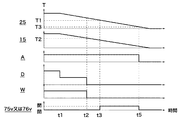
図2は、燃料電池20における発電を停止する際の燃料電池システム1の制御を説明するフローチャートである。図3は、図2に示す制御を行う際の燃料電池システム1の要素の状態を示すタイムチャートである。図3中、上下に並んだ5つのグラフにおいて、横軸は各グラフ共通で時間を示し、縦軸は、上のグラフから順に、アノード温度計25で検知された温度、酸化剤ガスAの流量、原料Dの流量、改質水Wの流量、開閉弁75v又は開閉弁76vの開閉状態を示している。以下の説明において、燃料電池システム1の構成に言及しているときは、図1を参照することとする。燃料電池20の発電中、制御装置90は、要求される燃料電池20の発電電力(典型的にはパワーコンディショナ(不図示)で設定される)を出力するのに必要な流量の改質ガスEをアノード21に供給するため、当該流量の改質ガスEを生成するのに必要な原料D及び改質水Wを改質器11に供給すると共に、必要な流量の酸化剤ガスAをカソード22に供給している(図3中の時刻t1まで)。このとき、開閉弁76vは閉じており、燃料電池20の温度は概ね600℃以上となっている。   FIG. 2 is a flowchart illustrating control of the fuel cell system 1 when power generation in the fuel cell 20 is stopped. FIG. 3 is a time chart showing states of elements of the fuel cell system 1 when the control shown in FIG. 2 is performed. In FIG. 3, in the five graphs arranged vertically, the horizontal axis indicates time common to each graph, and the vertical axis indicates the temperature detected by the anode thermometer 25 and the flow rate of the oxidant gas A in order from the upper graph. , The flow rate of the raw material D, the flow rate of the reforming water W, and the open / close state of the open / close valve 75v or the open / close valve 76v. In the following description, when referring to the configuration of the fuel cell system 1, reference is made to FIG. During power generation of the fuel cell 20, the control device 90 has a flow rate of reformed gas required to output the required power generated by the fuel cell 20 (typically set by a power conditioner (not shown)). In order to supply E to the anode 21, the raw material D and the reforming water W necessary for generating the reformed gas E at the flow rate are supplied to the reformer 11, and the oxidant gas A at the required flow rate is supplied to the cathode 21. 22 (until time t1 in FIG. 3). At this time, the on-off valve 76v is closed, and the temperature of the fuel cell 20 is approximately 600 ° C. or higher.

制御装置90は、図3中の時刻t1において、燃料電池20における発電を停止する旨の指令を受けたとき、燃料電池20の発電を停止する(発電停止工程:S1)。燃料電池20の発電の停止は、典型的にはパワーコンディショナ(不図示)の設定において燃料電池20の出力を0にすることにより行われる。制御装置90は、燃料電池20の発電を停止しても、カソード22への酸化剤ガスAの供給を継続して行う(酸化剤ガス供給継続工程:S2)。カソード22への酸化剤ガスAの供給を継続することにより、カソード22の冷却が促進される。その一方で、制御装置90は、改質器11に供給していた原料Dを、燃料電池20の発電時に供給していた流量よりも減少させ、これを改質水Wと混合させ(以下、流量を減少させた原料Dと改質水Wとが混合した流体を「減少混合流体R」という。)、減少混合流体Rを改質器11へ導入した後にアノード21に供給する(減少混合流体供給工程:S3)。減少混合流体Rを、改質器11を介してアノード21に供給することにより、改質器11及びアノード21の冷却が促進される。また、減少混合流体Rをアノード21に供給することにより、カソード22に供給されている酸化剤ガスAがアノード21に流入してくることに伴うアノード21の酸化を抑制している。   When the control device 90 receives a command to stop the power generation in the fuel cell 20 at time t1 in FIG. 3, the control device 90 stops the power generation of the fuel cell 20 (power generation stop step: S1). The power generation of the fuel cell 20 is typically stopped by setting the output of the fuel cell 20 to 0 in setting a power conditioner (not shown). The control device 90 continues to supply the oxidant gas A to the cathode 22 even when power generation of the fuel cell 20 is stopped (oxidant gas supply continuation step: S2). By continuing the supply of the oxidant gas A to the cathode 22, cooling of the cathode 22 is promoted. On the other hand, the control device 90 reduces the raw material D supplied to the reformer 11 below the flow rate supplied at the time of power generation of the fuel cell 20 and mixes it with the reforming water W (hereinafter referred to as “reformer water W”). A fluid in which the raw material D and the reforming water W having a reduced flow rate are mixed is referred to as a “reduced mixed fluid R”), and the reduced mixed fluid R is introduced into the reformer 11 and then supplied to the anode 21 (reduced mixed fluid). Supply process: S3). By supplying the reduced mixed fluid R to the anode 21 via the reformer 11, cooling of the reformer 11 and the anode 21 is promoted. Further, by supplying the reduced mixed fluid R to the anode 21, the oxidation of the anode 21 due to the oxidant gas A supplied to the cathode 22 flowing into the anode 21 is suppressed.

次に制御装置90は、アノード温度計25で検知した温度が第1の所定の温度T1に低下したか否かを判断する(S4)。第1の所定の温度T1は、アノード21が酸化雰囲気に晒されることで酸化が発生するリスクが低い任意の温度である。酸化雰囲気に起因した酸化は、温度が高いほど発生しやすく、温度が低くなると発生しにくくなる。本実施の形態では、第1の所定の温度T1を300℃としている。アノード温度計25で検知した温度が第1の所定の温度T1に低下したか否かを判断する工程(S4)において、第1の所定の温度T1に低下していない場合は、再び工程(S4)に戻る。他方、第1の所定の温度T1に低下した場合(図3中の時刻t3)、制御装置90は、原料ブロワ16及び改質水ポンプ13を停止して、改質器11への減少混合流体Rの供給を停止する(S5)。また、制御装置90は、開閉弁75v及び開閉弁76vの一方を開にする(S6)。   Next, the control device 90 determines whether or not the temperature detected by the anode thermometer 25 has decreased to the first predetermined temperature T1 (S4). The first predetermined temperature T1 is an arbitrary temperature at which the risk of oxidation occurring when the anode 21 is exposed to an oxidizing atmosphere is low. Oxidation due to the oxidizing atmosphere is more likely to occur as the temperature is higher, and is less likely to occur when the temperature is lower. In the present embodiment, the first predetermined temperature T1 is set to 300 ° C. In the step (S4) of determining whether or not the temperature detected by the anode thermometer 25 has decreased to the first predetermined temperature T1, if the temperature has not decreased to the first predetermined temperature T1, the step (S4) is performed again. Return to). On the other hand, when the temperature falls to the first predetermined temperature T1 (time t3 in FIG. 3), the control device 90 stops the raw material blower 16 and the reforming water pump 13, and reduces the mixed fluid to the reformer 11. The supply of R is stopped (S5). Further, the control device 90 opens one of the on-off valve 75v and the on-off valve 76v (S6).

改質器11への減少混合流体Rの供給を停止して開閉弁75v及び開閉弁76vのうちのいずれか一方を開にすると、酸化剤ガスブロワ28によってカソード22に供給されていた酸化剤ガスAがアノード21に逆流する。アノード21に逆流した酸化剤ガスAは、原料導入管51の方に向かって改質ガス管61等を流れ、排出管75及び排出管76のうち開にした開閉弁(75v又は76v)が配設されている排出ラインを流れて系外に排出される。これにより、アノード21に残留していた減少混合流体Rが、酸化剤ガスAによりパージされることとなる。このように、開閉弁(75v又は76v)を開にする工程(S6)は、アノードパージ工程に相当する。本実施の形態では、燃料電池20における発電を行う際に酸化剤ガスAをカソード22に供給する酸化剤ガスブロワ28を用いてアノード21のパージを行っており、このために特別な設備を設けていない。工程(S6)において、開閉弁75vを開にした場合は、酸化剤ガスブロワ28の稼働でアノード21に供給された酸化剤ガスAによって、改質器11及び気化器14をもパージすることができる。他方、開閉弁76vを開にした場合は、改質器11の酸化発生リスクのある温度の下限が燃料電池20の酸化発生リスクのある温度の下限より低い場合に、改質器11の酸化発生リスクを低減することができる。   When the supply of the reduced mixed fluid R to the reformer 11 is stopped and either one of the on-off valve 75v and the on-off valve 76v is opened, the oxidant gas A supplied to the cathode 22 by the oxidant gas blower 28 is opened. Flows back to the anode 21. The oxidant gas A that has flowed back to the anode 21 flows through the reformed gas pipe 61 and the like toward the raw material introduction pipe 51, and an open / close valve (75v or 76v) that is opened in the discharge pipe 75 and the discharge pipe 76 is arranged. It is discharged outside the system through the installed discharge line. As a result, the reduced mixed fluid R remaining on the anode 21 is purged by the oxidant gas A. Thus, the step (S6) of opening the on-off valve (75v or 76v) corresponds to an anode purge step. In the present embodiment, the anode 21 is purged by using the oxidant gas blower 28 that supplies the oxidant gas A to the cathode 22 when generating power in the fuel cell 20, and special equipment is provided for this purpose. Absent. In the step (S6), when the on-off valve 75v is opened, the reformer 11 and the vaporizer 14 can also be purged by the oxidant gas A supplied to the anode 21 by the operation of the oxidant gas blower 28. . On the other hand, when the on-off valve 76v is opened, oxidation of the reformer 11 occurs when the lower limit of the temperature at which the reformer 11 is at risk of oxidation is lower than the lower limit of the temperature at which the fuel cell 20 is at risk of oxidation. Risk can be reduced.

なお、酸化剤ガスAでアノード21をパージするのは、アノード21において電気化学反応による酸化が発生するのを抑制するためである。ここでいう電気化学反応による酸化とは、アノード21において、酸素が存在しても酸化雰囲気に起因した酸化が発生しにくいような低い温度で、触媒活性が低い場合において、局所的に電位差が生じることにより、アノード21に存在する酸素イオンがアノード21に残存している改質ガスE中の水素と反応できずに、アノード21に含まれているNi等の金属に反応して酸化することである。アノード21に電位差が生じる一因として、改質ガスEや酸化剤ガスAがアノード21に流入してくることにより、アノード21の近傍の雰囲気に濃度差が生じることが挙げられる。改質器11への減少混合流体Rの供給を停止する工程(S5)において減少混合流体R(改質ガスE)の供給を停止した状態では、アノード21の上流側(原料ブロワ16側)は閉止状態であるため、燃料電池20の発電停止時の温度低下に伴う熱収縮により、アノード21は、下流側から酸化剤ガスAを吸い込みやすい状況となる。端的に表現すると、アノード21は、上流側が改質ガスEの雰囲気、下流側が酸化剤ガスAの雰囲気の状態になる。アノード21を、酸化雰囲気に起因した酸化が発生するリスクが低い環境下で、酸化剤ガスAによってパージすることで、濃度差のない均一な雰囲気に置換することができ、起電力が生じない状況にすることができる。酸化剤ガスブロワ28でカソード22に供給した酸化剤ガスAをアノード21に逆流させるに際し、オフガスライン64にオリフィス64fが設けられているので、改質器11を介したアノード21への減少混合流体Rの供給を停止したときに、カソード22に供給された酸化剤ガスAをアノード21に導きやすくすることができる。なお、カソード22に供給する酸化剤ガスAの流量を、燃料電池20の発電時に供給していた流量よりも増加させることで、酸化剤ガスAをアノード21に逆流しやすくするようにしてもよい。   The reason for purging the anode 21 with the oxidant gas A is to suppress the occurrence of oxidation due to an electrochemical reaction at the anode 21. The oxidation by electrochemical reaction here means that a potential difference is locally generated in the anode 21 when the catalytic activity is low at a low temperature at which oxidation due to the oxidizing atmosphere hardly occurs even in the presence of oxygen. As a result, oxygen ions present in the anode 21 cannot react with the hydrogen in the reformed gas E remaining in the anode 21, but react with a metal such as Ni contained in the anode 21 to be oxidized. is there. One cause of the potential difference in the anode 21 is that the concentration difference is generated in the atmosphere in the vicinity of the anode 21 due to the reformed gas E and the oxidizing gas A flowing into the anode 21. In the state where the supply of the reduced mixed fluid R (reformed gas E) is stopped in the step (S5) of stopping the supply of the reduced mixed fluid R to the reformer 11, the upstream side of the anode 21 (the raw material blower 16 side) Since the fuel cell 20 is in the closed state, the anode 21 is likely to suck the oxidant gas A from the downstream side due to thermal contraction accompanying the temperature drop when the power generation of the fuel cell 20 is stopped. In short, the anode 21 is in a state of the atmosphere of the reformed gas E on the upstream side and the atmosphere of the oxidant gas A on the downstream side. The anode 21 is purged with the oxidant gas A in an environment where the risk of oxidation due to the oxidizing atmosphere is low, so that the anode 21 can be replaced with a uniform atmosphere with no concentration difference, and no electromotive force is generated. Can be. When the oxidant gas A supplied to the cathode 22 by the oxidant gas blower 28 is caused to flow back to the anode 21, since the orifice 64 f is provided in the off gas line 64, the reduced mixed fluid R to the anode 21 via the reformer 11 is provided. When the supply of the oxidant gas is stopped, the oxidant gas A supplied to the cathode 22 can be easily guided to the anode 21. The flow rate of the oxidant gas A supplied to the cathode 22 may be increased more than the flow rate supplied at the time of power generation of the fuel cell 20 to facilitate the backflow of the oxidant gas A to the anode 21. .

開閉弁(75v又は76v)を開にしたら(S6)、制御装置90は、アノード温度計25で検知した温度が第3の所定の温度T3に低下したか否かを判断する(S7)。第3の所定の温度T3は、アノード21の酸化雰囲気に起因した酸化及び電気化学反応による酸化が発生するリスクが低い任意の温度である。本実施の形態では、第3の所定の温度T3を90℃としている。アノード温度計25で検知した温度が第3の所定の温度T3に低下したか否かを判断する工程(S7)において、第3の所定の温度T3に低下していない場合は、再び工程(S7)に戻る。他方、第3の所定の温度T3に低下した場合(図3中の時刻t5)、制御装置90は、工程(S6)で開にした開閉弁(75v又は76v)を閉にする(S8)。また、制御装置90は、酸化剤ガスブロワ28を停止して、カソード22への酸化剤ガスAの供給を停止する(S9)。このように、アノード温度計25で検知した温度が第3の所定の温度T3に低下した時点で酸化剤ガスブロワ28を停止することで、酸化剤ガスブロワ28の動力を削減することができる。   When the on-off valve (75v or 76v) is opened (S6), the control device 90 determines whether or not the temperature detected by the anode thermometer 25 has dropped to the third predetermined temperature T3 (S7). The third predetermined temperature T3 is an arbitrary temperature with a low risk of oxidation due to the oxidizing atmosphere of the anode 21 and oxidation due to an electrochemical reaction. In the present embodiment, the third predetermined temperature T3 is 90 ° C. In the step of determining whether or not the temperature detected by the anode thermometer 25 has decreased to the third predetermined temperature T3 (S7), if the temperature has not decreased to the third predetermined temperature T3, the step (S7) is performed again. Return to). On the other hand, when the temperature falls to the third predetermined temperature T3 (time t5 in FIG. 3), the control device 90 closes the on-off valve (75v or 76v) opened in step (S6) (S8). Further, the control device 90 stops the oxidant gas blower 28 and stops the supply of the oxidant gas A to the cathode 22 (S9). Thus, the power of the oxidant gas blower 28 can be reduced by stopping the oxidant gas blower 28 when the temperature detected by the anode thermometer 25 is lowered to the third predetermined temperature T3.

以上で説明したように、本実施の形態に係る燃料電池システム1によれば、燃料電池20における発電の際に用いられる酸化剤ガスブロワ28から供給される酸化剤ガスAによってアノード21に残存する減少混合流体Rをパージするので、特別な設備(典型的には流体機械)を設けることなく、改質器11及び燃料電池20の酸化を抑制しつつ迅速な降温を行うことができる。また、開閉弁(75v又は76v)を開にする(S6)直前まで改質器11への減少混合流体Rの供給を継続するので、改質器11及び燃料電池20の冷却を促進させることができ、改質器11及び燃料電池20の降温に要する時間を短縮することができる。   As described above, according to the fuel cell system 1 according to the present embodiment, the reduction remaining in the anode 21 by the oxidant gas A supplied from the oxidant gas blower 28 used when generating power in the fuel cell 20. Since the mixed fluid R is purged, the temperature can be quickly lowered while suppressing oxidation of the reformer 11 and the fuel cell 20 without providing any special equipment (typically, a fluid machine). Further, since the supply of the reduced mixed fluid R to the reformer 11 is continued until just before the on-off valve (75v or 76v) is opened (S6), the cooling of the reformer 11 and the fuel cell 20 can be promoted. This can shorten the time required for the temperature of the reformer 11 and the fuel cell 20 to fall.

次に、図4及び図5を参照して、燃料電池20における発電を停止する際の燃料電池システム1の別の制御を説明する。図4は、燃料電池20における発電を停止する際の燃料電池システム1の別の制御を説明するフローチャートである。図5は、図4に示す制御を行う際の燃料電池システム1の要素の状態を示すタイムチャートである。図5中、上下に並んだ6つのグラフにおいて、横軸は各グラフ共通で時間を示し、縦軸は、上のグラフから順に、アノード温度計25で検知された温度、改質器温度計15で検知された温度、酸化剤ガスAの流量、原料Dの流量、改質水Wの流量、開閉弁75v又は開閉弁76vの開閉状態を示している。図4及び図5に示す別の制御は、図1に示す燃料電池システム1で行うことができる。以下の説明において燃料電池システム1の構成に言及しているときは、図1を参照することとする。   Next, another control of the fuel cell system 1 when power generation in the fuel cell 20 is stopped will be described with reference to FIGS. 4 and 5. FIG. 4 is a flowchart illustrating another control of the fuel cell system 1 when power generation in the fuel cell 20 is stopped. FIG. 5 is a time chart showing states of elements of the fuel cell system 1 when the control shown in FIG. 4 is performed. In FIG. 5, in the six graphs arranged vertically, the horizontal axis indicates time common to each graph, and the vertical axis indicates the temperature detected by the anode thermometer 25 and the reformer thermometer 15 in order from the upper graph. , The flow rate of the oxidizing gas A, the flow rate of the raw material D, the flow rate of the reforming water W, and the open / close state of the open / close valve 75v or the open / close valve 76v. The other control shown in FIGS. 4 and 5 can be performed by the fuel cell system 1 shown in FIG. When referring to the configuration of the fuel cell system 1 in the following description, reference is made to FIG.

図4に示す別の制御では、制御装置90が図5中の時刻t1において、燃料電池20における発電を停止する旨の指令を受けたとき、燃料電池20の発電を停止し(発電停止工程:S1)、カソード22への酸化剤ガスAの供給を継続し(酸化剤ガス供給継続工程:S2)、減少混合流体Rを改質器11へ導入した後にアノード21に供給する(減少混合流体供給工程:S3)までは、図2に示す制御と同様である。図4に示す別の制御では、減少混合流体供給工程(S3)の後、改質器温度計15で検知した温度が第2の所定の温度T2に低下したか否かを判断する(S4A)。第2の所定の温度T2は、改質器11における原料Dの水蒸気改質に適した温度帯の下限付近(典型的には下限値)の温度であり、第1の所定の温度T1よりも高い温度である。本実施の形態では、第2の所定の温度T2を400℃としている。改質器温度計15で検知した温度が第2の所定の温度T2に低下したか否かを判断する工程(S4A)において、第2の所定の温度T2に低下していない場合は、再び工程(S4A)に戻る。他方、第2の所定の温度T2に低下した場合(図5中の時刻t2)、制御装置90は、原料ブロワ16及び改質水ポンプ13を停止して、改質器11への減少混合流体Rの供給を停止する(S5)。   In another control shown in FIG. 4, when the control device 90 receives a command to stop power generation in the fuel cell 20 at time t1 in FIG. 5, the power generation of the fuel cell 20 is stopped (power generation stop step: S1) The supply of the oxidant gas A to the cathode 22 is continued (oxidant gas supply continuation step: S2), and the reduced mixed fluid R is introduced into the reformer 11 and then supplied to the anode 21 (reduced mixed fluid supply). The process up to step S3) is the same as the control shown in FIG. In another control shown in FIG. 4, it is determined whether or not the temperature detected by the reformer thermometer 15 has decreased to the second predetermined temperature T2 after the reduced mixed fluid supply step (S3) (S4A). . The second predetermined temperature T2 is a temperature in the vicinity of the lower limit (typically the lower limit value) of the temperature zone suitable for steam reforming of the raw material D in the reformer 11, and is higher than the first predetermined temperature T1. High temperature. In the present embodiment, the second predetermined temperature T2 is set to 400 ° C. In the step of determining whether the temperature detected by the reformer thermometer 15 has decreased to the second predetermined temperature T2 (S4A), if the temperature has not decreased to the second predetermined temperature T2, the step is performed again. Return to (S4A). On the other hand, when the temperature falls to the second predetermined temperature T2 (time t2 in FIG. 5), the control device 90 stops the raw material blower 16 and the reforming water pump 13, and reduces the mixed fluid to the reformer 11. The supply of R is stopped (S5).

図4に示す別の制御では、改質器11への減少混合流体Rの供給を停止したら(S5)、制御装置90は、アノード温度計25で検知した温度が第1の所定の温度T1に低下したか否かを判断する(S5A)。この工程は、図2に示す制御における工程(S4)と同様である。アノード温度計25で検知した温度が第1の所定の温度T1に低下したか否かを判断する工程(S5A)において、第1の所定の温度T1に低下していない場合は、再び工程(S5A)に戻る。他方、第1の所定の温度T1に低下した場合(図5中の時刻t3)、制御装置90は、開閉弁75v又は開閉弁76vを開にして(S6)、酸化剤ガスブロワ28によってカソード22に供給されていた酸化剤ガスAをアノード21に逆流させ、アノード21に残留していた減少混合流体Rを酸化剤ガスAによりパージする。開閉弁75v又は開閉弁76vを開にする工程(S6)以降の、アノード温度計25で検知した温度が第3の所定の温度T3に低下したか否かを判断する工程(S7)、第3の所定の温度T3に低下したときに(図5中の時刻t5)開閉弁75v又は開閉弁76vを閉にする工程(S8)、カソード22への酸化剤ガスAの供給を停止する工程(S9)は、図2に示す制御における対応する工程と同様である。   In another control shown in FIG. 4, when the supply of the reduced mixed fluid R to the reformer 11 is stopped (S5), the control device 90 causes the temperature detected by the anode thermometer 25 to reach the first predetermined temperature T1. It is determined whether or not it has decreased (S5A). This step is the same as the step (S4) in the control shown in FIG. In the step of determining whether or not the temperature detected by the anode thermometer 25 has decreased to the first predetermined temperature T1 (S5A), if the temperature has not decreased to the first predetermined temperature T1, the step (S5A) is performed again. Return to). On the other hand, when the temperature falls to the first predetermined temperature T1 (time t3 in FIG. 5), the control device 90 opens the on-off valve 75v or the on-off valve 76v (S6), and the oxidant gas blower 28 supplies the cathode 22 to the cathode 22. The supplied oxidant gas A is caused to flow back to the anode 21, and the reduced mixed fluid R remaining on the anode 21 is purged by the oxidant gas A. A step (S7), a step of determining whether or not the temperature detected by the anode thermometer 25 has been lowered to the third predetermined temperature T3 after the step (S6) of opening the on-off valve 75v or the on-off valve 76v. When the on-off valve 75v or the on-off valve 76v is closed (S8), and the supply of the oxidant gas A to the cathode 22 is stopped (S9). ) Is the same as the corresponding step in the control shown in FIG.

以上で説明したように、図4に示す別の制御においても、燃料電池20における発電の際に用いられる酸化剤ガスブロワ28によってアノード21に残存する減少混合流体Rをパージするので、特別な設備(典型的には流体機械)を設けることなく、改質器11及び燃料電池20の酸化を抑制しつつ迅速な降温を行うことができる。また、図4に示す別の制御では、改質器温度計15で検知された温度が第2の所定の温度T2まで低下したときに減少混合流体Rの供給を停止するので、減少混合流体R中の原料Dの改質が不十分なままアノード21に流入することを抑制することができ、ひいてはアノード21において原料Dが熱分解して炭素が析出することを抑制することができる。   As described above, even in the other control shown in FIG. 4, the reduced mixed fluid R remaining in the anode 21 is purged by the oxidant gas blower 28 used in the power generation in the fuel cell 20. The temperature can be quickly lowered while suppressing oxidation of the reformer 11 and the fuel cell 20 without providing a typical fluid machine. Further, in another control shown in FIG. 4, since the supply of the reduced mixed fluid R is stopped when the temperature detected by the reformer thermometer 15 is lowered to the second predetermined temperature T2, the reduced mixed fluid R is stopped. Inflow of the raw material D in the anode 21 with insufficient reforming of the raw material D therein can be suppressed, and as a result, the raw material D can be prevented from being thermally decomposed and precipitating carbon in the anode 21.

以上の説明では、原料供給部が原料ブロワ16であるとしたが、元圧のある外部から原料Dが供給される配管に設けられた弁等であってもよい。また、酸化剤ガス供給部が酸化剤ガスブロワ28であるとしたが、原料供給部と同様に、元圧のある外部から酸化剤ガスAが供給される配管に設けられた弁等であってもよい。   In the above description, the raw material supply unit is the raw material blower 16, but it may be a valve or the like provided in a pipe to which the raw material D is supplied from the outside having a source pressure. Further, although the oxidant gas supply unit is the oxidant gas blower 28, as with the raw material supply unit, a valve or the like provided in a pipe to which the oxidant gas A is supplied from the outside with the original pressure may be used. Good.

以上の説明では、アノード温度検知器が、アノード21の温度を直接検知するアノード温度計25であるとしたが、アノード21に導入される流体の温度を検知するアノード入口温度計を設ける等のアノード21の温度を間接的に検知することとしてもよく、あるいは、アノード21の周囲の雰囲気を検知する等のアノード21の温度と相関を有する温度を検知することとしてもよい。   In the above description, the anode temperature detector is the anode thermometer 25 that directly detects the temperature of the anode 21, but an anode such as an anode inlet thermometer that detects the temperature of the fluid introduced into the anode 21 is provided. The temperature of 21 may be detected indirectly, or a temperature having a correlation with the temperature of the anode 21 such as detecting the atmosphere around the anode 21 may be detected.

以上の説明では、改質部温度検知器が、改質器11の内部の温度を直接検知する改質器温度計15であるとしたが、改質器11に導入される流体の温度を検知する改質器入口温度計を設ける等の改質器11の温度を間接的に検知することとしてもよく、あるいは、改質器11の周囲の雰囲気を検知する等の改質器11の温度と相関を有する温度を検知することとしてもよい。なお、改質部温度検知器は、上述の図2に示す制御等、改質器11の温度を燃料電池20における発電の停止時の制御に用いない場合は設置せずに省略するとよい。また、改質器11が燃料電池20と同じ筐体に収容されていて燃料電池20における発電の停止時は筐体内全体が概ね同じ温度となるような、改質器11の温度がアノード21の温度と同じ又はアノード21の温度から推測できる状況のときは、アノード温度検知器が改質部温度検知器を兼ねることとして、改質部温度検知器を別途設けずに省略してもよい。   In the above description, the reformer temperature detector is the reformer thermometer 15 that directly detects the temperature inside the reformer 11, but the temperature of the fluid introduced into the reformer 11 is detected. The temperature of the reformer 11 may be detected indirectly, such as by providing a reformer inlet thermometer, or the temperature of the reformer 11 such as detecting the atmosphere around the reformer 11 It is good also as detecting the temperature which has a correlation. If the temperature of the reformer 11 is not used for control at the time of power generation stop in the fuel cell 20, such as the control shown in FIG. 2 described above, the reformer temperature detector may be omitted without being installed. Further, the reformer 11 is housed in the same casing as the fuel cell 20, and when the power generation in the fuel cell 20 is stopped, the temperature of the reformer 11 is such that the temperature in the entire casing is substantially the same. When the temperature is the same as the temperature or can be estimated from the temperature of the anode 21, the anode temperature detector may also serve as the reforming unit temperature detector, and may be omitted without providing the reforming unit temperature detector separately.

以上の説明では、オフガスライン64にオリフィス64f等の絞り流路が設けられていることとしたが、絞り流路に代えて、開度を調節可能な開度調節装置(典型的には流量調整弁)を設けることとしてもよい。開度調節装置を設けた場合、燃料電池20の発電を行っているときはオフガスライン64の抵抗を軽減するために開度を大きくし、燃料電池20の発電を停止した後にアノード21を酸化剤ガスAでパージするときは酸化剤ガスAをオフガスライン64よりもアノード21に流入させるために開度を小さくすることで、燃料電池システム1の適切な運転及び停止が可能になる。なお、オリフィス64f等の絞り流路あるいは開度調節装置は、オフガスライン64よりも下流側の排出口65eまでの間(排ガス管65)に設けられていてもよい。特に、開度調節装置を設ける場合は、極力下流側(熱交換部36の近傍)に設けることとすると、耐熱性能が比較的低いものも設置することが可能になるため好ましい。   In the above description, the off gas line 64 is provided with a throttle channel such as the orifice 64f. However, instead of the throttle channel, an opening degree adjusting device (typically, a flow rate adjustment) that can adjust the opening degree. A valve) may be provided. When the opening degree adjusting device is provided, when the fuel cell 20 is generating power, the opening degree is increased in order to reduce the resistance of the off-gas line 64, and after stopping the power generation of the fuel cell 20, the anode 21 is made to oxidize. When purging with the gas A, the fuel cell system 1 can be appropriately operated and stopped by reducing the opening in order to cause the oxidant gas A to flow into the anode 21 from the off-gas line 64. It should be noted that the throttle channel or the opening degree adjusting device such as the orifice 64f may be provided between the exhaust port 65e downstream of the off gas line 64 (exhaust gas pipe 65). In particular, when the opening degree adjusting device is provided, it is preferable that the opening degree adjusting device is provided on the downstream side (in the vicinity of the heat exchange unit 36) as much as possible because it is possible to install a device having a relatively low heat resistance.

以上の説明では、開閉弁75vが配設された排出管75が、混合原料Mの流れ方向で気化器14の上流側の原料導入管51に接続されているとしたが、改質器11と気化器14の間の原料導入管51に接続されていてもよい。また、開閉弁75vが配設された排出管75と、開閉弁76vが配設された排出管76とが設けられていることとしたが、流体を系外に排出する排出管が一方に決まっている場合は、開にしない開閉弁が配設されている排出管を設けなくてもよい。あるいは、開閉弁75vが配設された排出管75及び/又は開閉弁76vが配設された排出管76を設けることに代えて、酸化剤ガスブロワ28から吐出された酸化剤ガスAを、カソード22を経由せずにアノード21に導くバイパス管を設けることとしてもよい。   In the above description, the discharge pipe 75 provided with the on-off valve 75v is connected to the raw material introduction pipe 51 on the upstream side of the vaporizer 14 in the flow direction of the mixed raw material M. It may be connected to the raw material introduction pipe 51 between the vaporizers 14. Further, the exhaust pipe 75 provided with the on-off valve 75v and the exhaust pipe 76 provided with the on-off valve 76v are provided. However, one of the exhaust pipes for discharging the fluid out of the system is determined. In this case, it is not necessary to provide a discharge pipe provided with an on-off valve that is not opened. Alternatively, instead of providing the exhaust pipe 75 provided with the on-off valve 75v and / or the exhaust pipe 76 provided with the on-off valve 76v, the oxidant gas A discharged from the oxidant gas blower 28 is replaced with the cathode 22. Alternatively, a bypass pipe may be provided that leads to the anode 21 without going through.

図6は、本発明の実施の形態の変形例に係る燃料電池システム1Aの燃料電池20まわりの部分系統図である。燃料電池システム1Aでは、燃料電池システム1(図1参照)で設けられていた排出管76に代えて、バイパスライン68が設けられている。バイパスライン68は、酸化剤ガスブロワ28とカソード22との間の酸化剤ガス管62に一端が接続され、他端が改質ガス管61に接続されている。なお、バイパスライン68の他端は、アノード21に直接接続されていてもよい。バイパスライン68には、流路を開閉するバイパス弁68vが配設されている。バイパス弁68vは、制御装置90(図1参照)と信号ケーブルで接続されており、制御装置90(図1参照)からの指令により開閉が制御されるように構成されている。燃料電池システム1Aでは、オリフィス64f(図1参照)等の絞り流路は設けなくてもよい。燃料電池システム1Aの上記以外の構成は、燃料電池システム1(図1参照)と同様である。   FIG. 6 is a partial system diagram around the fuel cell 20 of the fuel cell system 1A according to a modification of the embodiment of the present invention. In the fuel cell system 1A, a bypass line 68 is provided instead of the discharge pipe 76 provided in the fuel cell system 1 (see FIG. 1). The bypass line 68 has one end connected to the oxidant gas pipe 62 between the oxidant gas blower 28 and the cathode 22, and the other end connected to the reformed gas pipe 61. Note that the other end of the bypass line 68 may be directly connected to the anode 21. The bypass line 68 is provided with a bypass valve 68v for opening and closing the flow path. The bypass valve 68v is connected to the control device 90 (see FIG. 1) via a signal cable, and is configured to be opened and closed by a command from the control device 90 (see FIG. 1). In the fuel cell system 1A, a throttle channel such as the orifice 64f (see FIG. 1) may not be provided. The other configuration of the fuel cell system 1A is the same as that of the fuel cell system 1 (see FIG. 1).

本変形例に係る燃料電池システム1Aでは、燃料電池20における発電を停止する際に図2又は図4に示す制御を行うにあたり、工程(S6)において開閉弁75v又は開閉弁76vを開にする代わりにバイパス弁68vを開にし、工程(S8)において開閉弁75v又は開閉弁76vを閉にする代わりにバイパス弁68vを閉にする。上記以外の工程は、図2又は図4に示す通りである。燃料電池システム1Aでは、工程(S6)においてバイパス弁68vを開にすると、酸化剤ガス管62を流れる酸化剤ガスAの一部がバイパスライン68に流入し、酸化剤ガスAが、燃料電池20の発電時における流体の流れ方向で、アノード21及びカソード22の双方に流れることとなる。このようにすることで、アノード21への酸化剤ガスAの供給を安定させることができる。なお、バイパス弁68vを開けた際、酸化剤ガスAがアノード21に適切に供給されるように、酸化剤ガスブロワ28から吐出される酸化剤ガスAの流量を増加させることとしてもよい。   In the fuel cell system 1A according to the present modification, when performing the control shown in FIG. 2 or FIG. 4 when stopping the power generation in the fuel cell 20, instead of opening the on-off valve 75v or the on-off valve 76v in the step (S6). The bypass valve 68v is opened, and in step (S8), the bypass valve 68v is closed instead of closing the on-off valve 75v or the on-off valve 76v. Steps other than the above are as shown in FIG. 2 or FIG. In the fuel cell system 1A, when the bypass valve 68v is opened in the step (S6), a part of the oxidant gas A flowing through the oxidant gas pipe 62 flows into the bypass line 68, and the oxidant gas A is converted into the fuel cell 20. The fluid flows in both the anode 21 and the cathode 22 in the direction of fluid flow during power generation. By doing so, the supply of the oxidant gas A to the anode 21 can be stabilized. Note that the flow rate of the oxidant gas A discharged from the oxidant gas blower 28 may be increased so that the oxidant gas A is appropriately supplied to the anode 21 when the bypass valve 68v is opened.

1 燃料電池システム
11 改質器
13 改質水ポンプ
16 原料ブロワ
20 燃料電池
21 アノード
22 カソード
25 アノード温度計
28 酸化剤ガスブロワ
62 酸化剤ガス管
64 オフガスライン
64f オリフィス
68 バイパスライン
68v バイパス弁
76v 開閉弁
90 制御装置
A 酸化剤ガス
D 原料
E 改質ガス
Fa カソードオフガス
R 減少混合流体
W 改質水
DESCRIPTION OF SYMBOLS 1 Fuel cell system 11 Reformer 13 Reformed water pump 16 Raw material blower 20 Fuel cell 21 Anode 22 Cathode 25 Anode thermometer 28 Oxidant gas blower 62 Oxidant gas pipe 64 Off-gas line 64f Orifice 68 Bypass line 68v Bypass valve 76v On-off valve 90 Controller A Oxidant gas D Raw material E Reformed gas Fa Cathode off-gas R Reduced mixed fluid W Reformed water

Claims (13)

炭化水素系の原料と改質水とを導入し、前記原料を、水素を含有する改質ガスに改質する改質部と;
前記原料を前記改質部に供給する原料供給部と;
前記改質水を前記改質部に供給する改質水供給部と;
前記改質部で生成された前記改質ガスを導入するアノードと、酸素を含有する酸化剤ガスを導入するカソードとを有し、発電する燃料電池と;
前記カソードに前記酸化剤ガスを供給する酸化剤ガス供給部と;
前記アノードの温度又は前記アノードの温度と相関を有する温度を直接又は間接的に検知するアノード温度検知器と;
前記燃料電池の発電停止後、前記カソードへの前記酸化剤ガスの供給を継続して行いつつ、前記燃料電池の発電時に前記改質部に供給されていた流量よりも少ない流量の前記原料が前記改質水と混合した減少混合流体を、前記改質部を介して前記アノードに供給して前記燃料電池及び前記改質部を冷却し、その後、前記改質部及び前記アノードへの前記減少混合流体の供給停止以後の前記アノード温度検知器で検知した温度が第1の所定の温度になったときに前記酸化剤ガス供給部によって前記酸化剤ガスを前記アノードに供給するように、前記原料供給部、前記改質水供給部、前記酸化剤ガス供給部を制御する制御部とを備える;
燃料電池システム。
A reforming section for introducing a hydrocarbon-based raw material and reforming water, and reforming the raw material into a reformed gas containing hydrogen;
A raw material supply unit for supplying the raw material to the reforming unit;
A reforming water supply unit for supplying the reforming water to the reforming unit;
A fuel cell having an anode for introducing the reformed gas generated in the reforming section and a cathode for introducing an oxidant gas containing oxygen;
An oxidant gas supply unit for supplying the oxidant gas to the cathode;
An anode temperature detector for directly or indirectly detecting the temperature of the anode or a temperature correlated with the temperature of the anode;
After the power generation of the fuel cell is stopped, while the supply of the oxidant gas to the cathode is continued, the raw material having a flow rate smaller than the flow rate supplied to the reforming unit at the time of power generation of the fuel cell is A reduced mixed fluid mixed with reforming water is supplied to the anode via the reforming unit to cool the fuel cell and the reforming unit, and then the reduced mixing to the reforming unit and the anode. The raw material supply so that the oxidant gas is supplied to the anode by the oxidant gas supply unit when the temperature detected by the anode temperature detector after the supply of fluid is stopped reaches a first predetermined temperature. And a control unit for controlling the reforming water supply unit and the oxidant gas supply unit;
Fuel cell system.
前記制御部は、前記アノード温度検知器で検知した温度が前記第1の所定の温度になったときに、前記改質部及び前記アノードへの前記減少混合流体の供給を停止すると共に前記酸化剤ガス供給部によって前記酸化剤ガスを前記アノードに供給する;
請求項1に記載の燃料電池システム。
The control unit stops supplying the reduced mixed fluid to the reforming unit and the anode when the temperature detected by the anode temperature detector reaches the first predetermined temperature, and the oxidant. Supplying the oxidant gas to the anode by a gas supply;
The fuel cell system according to claim 1.
前記改質部の温度又は前記改質部の温度と相関を有する温度を直接又は間接的に検知する改質部温度検知器を備え;
前記制御部は、前記改質部温度検知器で検知した温度が前記第1の所定の温度よりも高い第2の所定の温度まで低下した時点で前記改質部及び前記アノードへの前記減少混合流体の供給を停止する;
請求項1に記載の燃料電池システム。
A reforming section temperature detector for directly or indirectly detecting the temperature of the reforming section or a temperature correlated with the temperature of the reforming section;
The controller is configured to reduce the mixing to the reforming unit and the anode when the temperature detected by the reforming unit temperature detector is lowered to a second predetermined temperature higher than the first predetermined temperature. Stop supplying fluid;
The fuel cell system according to claim 1.
前記燃料電池の発電時の前記改質ガスの流れ方向における前記アノードの上流側に設けられ、前記酸化剤ガス供給部によって前記アノードに供給された前記酸化剤ガスを系外に排出する開閉弁を備え;
前記制御部は、酸化剤ガス供給部によって前記酸化剤ガスが前記アノードに供給されているときに前記開閉弁を開にするように、前記開閉弁を制御する;
請求項1乃至請求項3のいずれか1項に記載の燃料電池システム。
An on-off valve provided upstream of the anode in the flow direction of the reformed gas during power generation of the fuel cell and discharging the oxidant gas supplied to the anode by the oxidant gas supply unit out of the system; Preparation;
The control unit controls the on-off valve to open the on-off valve when the oxidizing gas is supplied to the anode by the oxidizing gas supply unit;
The fuel cell system according to any one of claims 1 to 3.
前記制御部は、前記酸化剤ガス供給部によって前記酸化剤ガスを前記アノードに供給するときに、前記燃料電池の発電時に前記カソードに供給されていた流量よりも多い流量の前記酸化剤ガスが前記酸化剤ガス供給部から供給されるように、前記酸化剤ガス供給部を制御する;
請求項4に記載の燃料電池システム。
When the oxidant gas supply unit supplies the oxidant gas to the anode, the control unit supplies the oxidant gas having a flow rate higher than that supplied to the cathode during power generation of the fuel cell. Controlling the oxidant gas supply to be supplied from the oxidant gas supply;
The fuel cell system according to claim 4.
前記開閉弁が、前記改質部と前記アノードとの間に設けられた;
請求項4又は請求項5に記載の燃料電池システム。
The on-off valve is provided between the reforming section and the anode;
The fuel cell system according to claim 4 or 5.
前記開閉弁が、前記燃料電池の発電時の前記原料の流れ方向における前記改質部の上流側に設けられた;
請求項4又は請求項5に記載の燃料電池システム。
The on-off valve is provided upstream of the reforming unit in the flow direction of the raw material during power generation of the fuel cell;
The fuel cell system according to claim 4 or 5.
前記燃料電池の発電時に前記カソードに供給された前記酸化剤ガスのうちの前記燃料電池における発電に利用されなかったカソードオフガスを前記カソードの外に排出するオフガスラインと;
前記オフガスラインから系外に流体を排出する排出口までの間に設けられた絞り流路とを備える;
請求項4乃至請求項7のいずれか1項に記載の燃料電池システム。
An off-gas line for discharging a cathode off-gas that has not been used for power generation in the fuel cell, out of the cathode, out of the oxidant gas supplied to the cathode during power generation of the fuel cell;
A throttle channel provided between the off-gas line and a discharge port for discharging the fluid out of the system;
The fuel cell system according to any one of claims 4 to 7.
前記燃料電池の発電時に前記カソードに供給された前記酸化剤ガスのうちの前記燃料電池における発電に利用されなかったカソードオフガスを前記カソードの外に排出するオフガスラインと;
前記オフガスラインから系外に流体を排出する排出口までの間に設けられ、開度を調節可能な開度調節装置とを備える;
請求項4乃至請求項7のいずれか1項に記載の燃料電池システム。
An off-gas line for discharging a cathode off-gas that has not been used for power generation in the fuel cell, out of the cathode, out of the oxidant gas supplied to the cathode during power generation of the fuel cell;
An opening adjusting device provided between the off-gas line and a discharge port for discharging the fluid to the outside of the system and capable of adjusting the opening;
The fuel cell system according to any one of claims 4 to 7.
前記酸化剤ガス供給部から吐出された前記酸化剤ガスを前記カソードに導く酸化剤ガスラインと;
前記酸化剤ガスラインと前記アノードとを連絡するバイパスラインとを備え;
前記バイパスラインは、流路を開閉可能なバイパス弁を有し;
前記制御部は、前記酸化剤ガス供給部によって前記酸化剤ガスを前記アノードに供給するときに、前記酸化剤ガス供給部から吐出された前記酸化剤ガスが前記バイパスラインに流入するように前記バイパス弁を制御する;
請求項1乃至請求項3のいずれか1項に記載の燃料電池システム。
An oxidant gas line for guiding the oxidant gas discharged from the oxidant gas supply unit to the cathode;
A bypass line connecting the oxidant gas line and the anode;
The bypass line has a bypass valve capable of opening and closing the flow path;
When the oxidant gas supply unit supplies the oxidant gas to the anode, the controller may bypass the bypass so that the oxidant gas discharged from the oxidant gas supply unit flows into the bypass line. Control the valve;
The fuel cell system according to any one of claims 1 to 3.
前記制御部は、前記アノード温度検知器で検知した温度が前記第1の所定の温度よりも低い第3の所定の温度になったときに前記酸化剤ガス供給部を停止する;
請求項1乃至請求項10のいずれか1項に記載の燃料電池システム。
The control unit stops the oxidant gas supply unit when a temperature detected by the anode temperature detector reaches a third predetermined temperature lower than the first predetermined temperature;
The fuel cell system according to any one of claims 1 to 10.
炭化水素系の原料に改質水を加えて改質部に導入し改質して水素を含有する改質ガスを生成し、前記改質ガスを燃料電池のアノードに供給すると共に酸素を含有する酸化剤ガスを酸化剤ガス供給部によって前記燃料電池のカソードに供給して発電する燃料電池システムの運転を停止する方法であって;
前記燃料電池の発電を停止する発電停止工程と;
前記発電停止工程の後、前記カソードへの前記酸化剤ガスの供給を継続して行う酸化剤ガス供給継続工程と;
前記酸化剤ガス供給継続工程と並行して、前記燃料電池の発電時に前記改質部に供給されていた流量よりも少ない流量の前記原料が前記改質水と混合した減少混合流体を、前記改質部を介して前記アノードに供給して前記燃料電池及び前記改質部を冷却する減少混合流体供給工程と;
前記減少混合流体供給工程を終了した後、前記アノードの温度又は前記アノードの温度と相関を有する温度が第1の所定の温度になったときに前記酸化剤ガス供給部によって前記酸化剤ガスを前記アノードに供給するアノードパージ工程とを備える;
燃料電池システムの停止方法。
A reforming water is added to a hydrocarbon-based raw material and introduced into a reforming section to generate a reformed gas containing hydrogen, which is supplied to the anode of the fuel cell and contains oxygen. A method for stopping operation of a fuel cell system for generating power by supplying an oxidant gas to a cathode of the fuel cell by an oxidant gas supply unit;
A power generation stopping step of stopping power generation of the fuel cell;
An oxidant gas supply continuation step of continuously supplying the oxidant gas to the cathode after the power generation stop step;
In parallel with the oxidant gas supply continuation step, a reduced mixed fluid in which the raw material having a flow rate smaller than the flow rate supplied to the reforming unit at the time of power generation of the fuel cell is mixed with the reforming water is changed to the reformed water. A reduced mixed fluid supply step of cooling the fuel cell and the reforming section by supplying to the anode through a mass section;
After the reduced mixed fluid supplying step, when the temperature of the anode or a temperature correlated with the temperature of the anode reaches a first predetermined temperature, the oxidizing gas is supplied by the oxidizing gas supply unit. An anode purge step for feeding to the anode;
How to stop the fuel cell system.
請求項1乃至請求項11のいずれか1項に記載の燃料電池システムを用いて電力を生産する方法であって;
前記改質部に前記原料及び前記改質水を供給して前記改質ガスを生成する工程と;
前記改質ガスを前記アノードに供給すると共に前記酸化剤ガスを前記カソードに供給して前記燃料電池において発電する工程と;
前記燃料電池で発電された電力を需要家に向けて放出する工程と;
前記燃料電池の発電を停止する工程とを備える;
電力生産方法。
A method for producing electric power using the fuel cell system according to any one of claims 1 to 11,
Supplying the raw material and the reformed water to the reforming unit to generate the reformed gas;
Supplying the reformed gas to the anode and supplying the oxidant gas to the cathode to generate electricity in the fuel cell;
Releasing the electric power generated by the fuel cell toward a consumer;
Stopping the power generation of the fuel cell;
Electricity production method.
JP2015130683A 2015-06-30 2015-06-30 Fuel cell system, stop method for fuel cell system, and power production method Pending JP2017016816A (en)

Priority Applications (1)

Application Number Priority Date Filing Date Title
JP2015130683A JP2017016816A (en) 2015-06-30 2015-06-30 Fuel cell system, stop method for fuel cell system, and power production method

Applications Claiming Priority (1)

Application Number Priority Date Filing Date Title
JP2015130683A JP2017016816A (en) 2015-06-30 2015-06-30 Fuel cell system, stop method for fuel cell system, and power production method

Publications (1)

Publication Number Publication Date
JP2017016816A true JP2017016816A (en) 2017-01-19

Family

ID=57830885

Family Applications (1)

Application Number Title Priority Date Filing Date
JP2015130683A Pending JP2017016816A (en) 2015-06-30 2015-06-30 Fuel cell system, stop method for fuel cell system, and power production method

Country Status (1)

Country Link
JP (1) JP2017016816A (en)

Cited By (1)

* Cited by examiner, † Cited by third party
Publication number Priority date Publication date Assignee Title
JP7445416B2 (en) 2019-12-02 2024-03-07 日産自動車株式会社 Control method for fuel cell system and fuel cell system

Cited By (1)

* Cited by examiner, † Cited by third party
Publication number Priority date Publication date Assignee Title
JP7445416B2 (en) 2019-12-02 2024-03-07 日産自動車株式会社 Control method for fuel cell system and fuel cell system

Similar Documents

Publication Publication Date Title
JP5164441B2 (en) Starting method of fuel cell system
JP5138324B2 (en) Reformer and fuel cell system
EP2124282B1 (en) Reformer system, fuel cell system, and their operation method
JP5763405B2 (en) Fuel cell system
WO2007137068A1 (en) Fuel cell system and operting method thereof
TWI422095B (en) A reformer system, a fuel cell system and a method of operation
JP5852011B2 (en) Fuel cell system
JP2009176660A (en) Shutdown method of indirect internal reforming solid oxide fuel cell
JP2009238591A (en) Load following operation method of fuel cell system
JP2008176943A (en) Fuel cell system
WO2012091121A1 (en) Fuel cell system
JP2007323972A (en) Fuel treating device and fuel cell system
JP2010044909A (en) Shutdown method of indirect internally reformed solid oxide fuel cell
JP5002220B2 (en) Fuel cell system
JP5982665B2 (en) Fuel cell system
JP2017016816A (en) Fuel cell system, stop method for fuel cell system, and power production method
JP2009283278A (en) Fuel cell system
JP5291915B2 (en) Indirect internal reforming type solid oxide fuel cell and operation method thereof
US7745060B2 (en) Fuel cell system and method of operating the fuel cell system
JP5166829B2 (en) Reformer and fuel cell system
JP2015191692A (en) Method of stopping fuel battery system and fuel battery system
KR101335504B1 (en) Fuel cell apparatus with single discharge port
JP2008081369A (en) Apparatus for producing hydrogen, its operating method and fuel cell system
JP2016119151A (en) Fuel cell system and operation method of fuel cell system
JP5086743B2 (en) Fuel cell system