EP2660609B1 - Drehzahlerkennungsverfahren und vorrichtung dafür, verfahren zur erkennung der viskosität einer reaktionsflüssigkeit und vorrichtung dafür sowie verfahren zur herstellung eines reaktionsprodukts - Google Patents
Drehzahlerkennungsverfahren und vorrichtung dafür, verfahren zur erkennung der viskosität einer reaktionsflüssigkeit und vorrichtung dafür sowie verfahren zur herstellung eines reaktionsprodukts Download PDFInfo
- Publication number
- EP2660609B1 EP2660609B1 EP11853581.4A EP11853581A EP2660609B1 EP 2660609 B1 EP2660609 B1 EP 2660609B1 EP 11853581 A EP11853581 A EP 11853581A EP 2660609 B1 EP2660609 B1 EP 2660609B1
- Authority
- EP
- European Patent Office
- Prior art keywords
- induction motor
- rotating shaft
- rotary speed
- viscosity
- order approximation
- Prior art date
- Legal status (The legal status is an assumption and is not a legal conclusion. Google has not performed a legal analysis and makes no representation as to the accuracy of the status listed.)
- Not-in-force
Links
Images


Classifications
-
- G—PHYSICS
- G01—MEASURING; TESTING
- G01P—MEASURING LINEAR OR ANGULAR SPEED, ACCELERATION, DECELERATION, OR SHOCK; INDICATING PRESENCE, ABSENCE, OR DIRECTION, OF MOVEMENT
- G01P3/00—Measuring linear or angular speed; Measuring differences of linear or angular speeds
- G01P3/42—Devices characterised by the use of electric or magnetic means
- G01P3/44—Devices characterised by the use of electric or magnetic means for measuring angular speed
-
- G—PHYSICS
- G01—MEASURING; TESTING
- G01N—INVESTIGATING OR ANALYSING MATERIALS BY DETERMINING THEIR CHEMICAL OR PHYSICAL PROPERTIES
- G01N11/00—Investigating flow properties of materials, e.g. viscosity, plasticity; Analysing materials by determining flow properties
- G01N11/10—Investigating flow properties of materials, e.g. viscosity, plasticity; Analysing materials by determining flow properties by moving a body within the material
- G01N11/14—Investigating flow properties of materials, e.g. viscosity, plasticity; Analysing materials by determining flow properties by moving a body within the material by using rotary bodies, e.g. vane
-
- G—PHYSICS
- G01—MEASURING; TESTING
- G01P—MEASURING LINEAR OR ANGULAR SPEED, ACCELERATION, DECELERATION, OR SHOCK; INDICATING PRESENCE, ABSENCE, OR DIRECTION, OF MOVEMENT
- G01P3/00—Measuring linear or angular speed; Measuring differences of linear or angular speeds
-
- H—ELECTRICITY
- H02—GENERATION; CONVERSION OR DISTRIBUTION OF ELECTRIC POWER
- H02P—CONTROL OR REGULATION OF ELECTRIC MOTORS, ELECTRIC GENERATORS OR DYNAMO-ELECTRIC CONVERTERS; CONTROLLING TRANSFORMERS, REACTORS OR CHOKE COILS
- H02P21/00—Arrangements or methods for the control of electric machines by vector control, e.g. by control of field orientation
- H02P21/14—Estimation or adaptation of machine parameters, e.g. flux, current or voltage
- H02P21/18—Estimation of position or speed
-
- H—ELECTRICITY
- H02—GENERATION; CONVERSION OR DISTRIBUTION OF ELECTRIC POWER
- H02P—CONTROL OR REGULATION OF ELECTRIC MOTORS, ELECTRIC GENERATORS OR DYNAMO-ELECTRIC CONVERTERS; CONTROLLING TRANSFORMERS, REACTORS OR CHOKE COILS
- H02P29/00—Arrangements for regulating or controlling electric motors, appropriate for both AC and DC motors
- H02P29/60—Controlling or determining the temperature of the motor or of the drive
- H02P29/64—Controlling or determining the temperature of the winding
-
- G—PHYSICS
- G01—MEASURING; TESTING
- G01N—INVESTIGATING OR ANALYSING MATERIALS BY DETERMINING THEIR CHEMICAL OR PHYSICAL PROPERTIES
- G01N11/00—Investigating flow properties of materials, e.g. viscosity, plasticity; Analysing materials by determining flow properties
- G01N2011/0046—In situ measurement during mixing process
- G01N2011/0053—In situ measurement during mixing process using ergometry; measuring power consumption
-
- H—ELECTRICITY
- H02—GENERATION; CONVERSION OR DISTRIBUTION OF ELECTRIC POWER
- H02P—CONTROL OR REGULATION OF ELECTRIC MOTORS, ELECTRIC GENERATORS OR DYNAMO-ELECTRIC CONVERTERS; CONTROLLING TRANSFORMERS, REACTORS OR CHOKE COILS
- H02P2207/00—Indexing scheme relating to controlling arrangements characterised by the type of motor
- H02P2207/01—Asynchronous machines
-
- H—ELECTRICITY
- H02—GENERATION; CONVERSION OR DISTRIBUTION OF ELECTRIC POWER
- H02P—CONTROL OR REGULATION OF ELECTRIC MOTORS, ELECTRIC GENERATORS OR DYNAMO-ELECTRIC CONVERTERS; CONTROLLING TRANSFORMERS, REACTORS OR CHOKE COILS
- H02P6/00—Arrangements for controlling synchronous motors or other dynamo-electric motors using electronic commutation dependent on the rotor position; Electronic commutators therefor
- H02P6/14—Electronic commutators
- H02P6/16—Circuit arrangements for detecting position
- H02P6/18—Circuit arrangements for detecting position without separate position detecting elements
Definitions
- the present invention generally relates to a rotary speed detection method of a rotating shaft of an induction motor and a detection device using the same for detecting the rotary speed of the rotating shaft of the induction motor, a rotational torque detection method of a rotating shaft of an induction motor and a detection device using the same for detecting the rotary torque of the rotating shaft of the induction motor, a reaction liquid viscosity detection method and a reaction liquid viscosity detection device and a manufacturing method of a reaction product.
- Measuring instruments for measuring rotary speed are generally categorized into: contact type (mechanical type) and non-contact type (optical type, electromagnetic type) according to the manner of measurement, digital and analog according to the processing method of the measurement signal, and explosion-proof and non-explosion-proof according to the place of use. Particularly, in the manufacturing sites at which resins, such as urethane, varnish, phenol and the like, are manufactured via chemical reaction, using the explosion-proof measuring instruments is required.
- measuring instruments of rotary speed known as the conventional ones are: handy digital tachometer which includes both contact type and non-contact type (Ono Sokki HT-5500), visible light type takohai tester (Hioki FT3405), electromagnetic rotary measuring instrument (Hioki MP-200), explosion-proof rotary measuring instrument (Ono Sokki RP-200) and the like. These measuring instruments are capable of both high accuracy and safety in use by being appropriately selected based on the type of application.
- the inventors of the present invention provides a reaction liquid viscosity detector (Patent Reference 1), wherein an induction motor driven by an inverter is used as a power source and the detector is installed in a reactor which performs the agitating the reaction liquid by rotating a rotational shaft having an agitation blade.
- Patent Reference 1 From Japan Laid Open Publication No. 2010-190882 (hereinafter referred to as Patent Reference 1) an operation method of rotary torque using power, voltage, current rotational speed of a rotational shaft, and an inverter output frequency applied to operate an electric motor is known.
- a current detection means, a voltage detection means, a rotational speed detection means and a frequency detection means is provided. Based on respective outputs, the rotary torque is calculated.
- US 2003/0033859 A1 relates to an apparatus and a method for determining the viscosity of a fluid.
- the device includes an electrical rotary device with a stator having a stator winding and a rotational body which can rotate in the fluid.
- WO 2009/151156 A1 relates to a flywheel induction motor connected in parallel to an inverter-controlled load and a control network.
- a stand-alone power system delivers power to the inverter-controller load and the flywheel induction motor.
- US 5,057,760 relates to an AC induction motor control apparatus which includes the determination of the motor torque by one of the use of a torque versus dc input power lookup table for each of selected motor speeds below a predetermined speed and by a mathematic calculation of a plurality of power losses in relation to the dc input power and the inverter frequency for motor speeds above that selected speed.
- the rotational speed detection means is dispensable and used as an instrument to obtain the rotational speed of the rotating shaft of the induction motor.
- the rotational speed detection means used in the manufacturing sites that deals with reaction liquid must meet the explosion-proof criteria.
- the rotational speed detection means which meets the explosion-proof criteria is expensive and has the disadvantages of increasing the installation cost of the viscosity detector, longer delivery period, and being hard to be popularized because the production line has to be stopped during installation. Accordingly, without using a rotational speed detector to detect the rotary speed of the rotating shaft of the induction motor is desired.
- the present invention is to provide a rotary speed detection method of the rotating shaft of the induction motor according to claim 1 and a device thereof capable of achieving the same accuracy as the measured value obtained from the rotational speed detection means according to claim 3.
- the features of the dependent claims define embodiments.
- the present invention provides a rotary torque detection method of the rotating shaft of the induction motor according to claim 5 and a device thereof according to claim 6.
- the present invention provides a viscosity acquiring method of a material which is agitated by the induction motor according to claim 7 and a method for manufacturing a reaction product using a viscosity acquiring method of a material which is agitated by the induction motor according to claim 9.
- slip S is specified by the rotary speed of the rotating magnetic field (synchronous speed) N S and the rotary speed of the rotor (actual rotary speed of the induction motor) N.
- the slip S and the mechanical output PM are substantially proportional to each other up to the range of the rated mechanical output P 0 and rated slip S 0 . Accordingly, by obtaining the slip S based on the relationship between the slip S and the mechanical output PM, the rotary speed of the rotating shaft of the induction motor can be obtained. Then, in the following, the unit of the rotary speed is treated as number of revolutions per minute min -1 .
- the mechanical output PM is an unknown value.
- Patent reference 1 since the mechanical output PM is obtained by subtracting the loss power P L from the power input P I , in order to obtain the loss power P L the rotary speed of the rotating shaft of the induction motor is necessary. Accordingly, the rotary speed of the rotating shaft of the induction motor cannot obtained simply based on the relationship between the slip S and the mechanical output PM.
- the inventors of the present invention focus on dividing the loss power P L into the loss power A which does not depend on the rotary speed of the rotating shaft of the induction motor (hereinafter, represented as “non-depending loss power A”) and the loss power B which depends on the rotary speed of the rotating shaft of the induction motor (hereinafter, represented as “depending loss power B"). Then, the present invention is completed by applying the approximate value of the mechanical output PM, which is calculated that merely the non-depending loss power A, except for the depending loss power B, is regarded as the loss power P L , to the relationship between the slip S and the mechanical output PM so as to obtain the rotary speed of the rotating shaft of the induction motor.
- the present invention relates to the rotary speed detection method of the rotating shaft of the induction motor according to claim 1 which includes a process of dividing the loss power P L into the non-depending loss power A and the depending loss power B, wherein P L is the loss power when the power input P I is supplied to the induction motor, and the following step I, step II and step III are included.
- Step II Based on the first order approximation value N 1 , the depending loss power B 1 is obtained.
- the second order approximation value N 2 is treated as a detected rotary speed of the rotating shaft.
- the speed detection method including the above mentioned step I to step III, without employing a measuring instrument, the rotary speed of the rotating shaft of the induction motor can be obtained with high accuracy.
- the second order approximation value N 2 (second approximation speed) obtained from the step III is substituted for the first order approximation value N 1 (first approximation speed) of the step I, and the step II and the step III are sequentially repeated.
- n is an integer equal to or greater than 2.
- the present invention provides a detection device according to claim 3 which performs the above mentioned rotary speed detection method of the rotating shaft of the induction motor (the rotary speed detection device of the rotating shaft of the induction motor).
- the detection device includes an information obtaining unit for obtaining the measurement information including power, current, voltage and voltage frequency supplied to the induction motor, and a calculation processing unit for obtaining the rotary speed via calculation based on the measurement information.
- the calculation processing unit performs the processing defined in the above mentioned step I, step II and step III.
- the calculation processing unit of the detection device can perform the processing of obtaining the third order approximate speed, fourth order approximate speed, ... , n th order approximate speed.
- it is the same as the following described rotary torque detection method and detection device of the rotating shaft of the induction motor, viscosity detection method of reaction liquid and viscosity detection device of reaction liquid, and manufacturing method of reaction product.
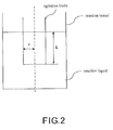
- the to-be-detected viscosity is the viscosity ⁇ of the reaction liquid when the reaction liquid is agitated by the rotation of agitation blade connected to the rotating shaft of the induction motor which serves as the power source.
- ⁇ is the constant determined according to the dimensions of the agitation blade and the reaction vessel used to agitate the reaction liquid.
- the present invention provides a manufacturing method of a reaction product, wherein at least one kind of compound is used as a raw material.
- the viscosity of the reaction product is changed with the reaction process of the raw material when the reaction product is manufactured.
- the method is characterized by including the detection method of rotary speed of the rotating shaft of the induction motor (first process), the detection method of rotary torque of the rotating shaft of the induction motor (second process) and the viscosity acquiring method of reaction product (third process).
- the rotary speed can be detected with high accuracy without employing the speed measurement instrument as an entity.
- the delivery period can also be shortened.
- the viscosity of reaction product can be observed in real time. Therefore, the unstableness in the endpoint of the reaction of the manufacturing lot can be reduced and the stabilization of the physical properties of the product is resulted.
- Equation (1) The slip S, as well known, is specified by the following Equation (1), wherein the synchronous speed is N S and the rotary speed of the rotor (the actual rotary speed of the rotating shaft of the induction motor) is N.
- S N S ⁇ N / N S
- Equation (1) is rewritten as Equation (1') so as to solve N.
- N N S 1 ⁇ S
- the rotary speed of the rotating shaft of the induction motor can be obtained if the slip S can be specified. Then, the slip S is used so that the rotary speed of the rotating shaft of the induction motor is obtained in the present invention.
- the slip S is the basic characteristic provided with the induction motor.
- the relationship between the slip S and the mechanical output PM is shown in FIG. 1 .
- the slip S and the mechanical output PM are substantially proportional to each other and in a linear correlation, and the correlation of the following Equation (2) is established.
- Equation (2) ⁇ is the specific constant of the induction motor, and the ratio of the rated mechanical output PM 0 to the rated slip S 0 is given as PM 0 /S 0 .
- the loss power P L of the induction motor may consist of primary copper loss, second copper loss, iron loss, mechanical loss, floating loss and the like. And, each loss is generated by individual reasons in which the primary copper loss is the joule heat due to the electrical resistance of the stator winding wire and the secondary copper loss is the joule heat due to the electrical resistance of the rotor winding wire.
- the iron loss is the loss generated when any of rotation and magnetic field occurs and consists of hysteresis loss and eddy-current loss.
- the mechanical loss is due to the friction or air drag generated by the rotation of the axis
- the floating loss is the constant of specific loss determined by the induction motor.
- the loss except the floating loss, can be obtained by calculation using the voltage, the current, the power frequency, the rotary speed and the motor circuit constant during the operating of the induction motor (paragraphs [0028] to [0040] of Patent reference 1). The factor of each loss is described as follow.
- Equation (3) can be rewritten into Equation (3').
- PM P ⁇ A + B [non-depending loss power A] primary copper loss, eddy-current loss, hysteresis loss, floating loss [depending loss power B] secondary copper loss, mechanical loss
- Equation (2) the first order approximation value of slip S 1 can be obtained from the following Equation (5).
- S 0 is the rated slip and the P 0 is the rated mechanical output.
- Equation (1') the first order approximation value of the rotary speed of the rotating shaft of the induction motor N 1 corresponding to the first order approximation value of slip S 1 can be obtained by using the following Equation (6).
- N S is the synchronous speed.
- N 1 N S 1 ⁇ S 1
- step I the description with respect to the rotary speed detection method of the rotating shaft of the induction motor of the present invention related to step I, and the method related to step II and step III is described as follows.
- the first order approximation value of the rotary speed N 1 obtained from step I can be treated as the detected result of the rotary speed according to the application purposes.
- step II the first order approximation value B 1 of the depending loss power B corresponding to the first order approximation value of rotary speed of the rotating shaft of the induction motor N 1 obtained from step I is obtained by setting to ⁇ (N 1 ) according to the well-known correlation equation obtained by the analysis of equivalent circuit of induction motor. The details thereof are illustrated in [depending loss power B n (W)].
- the second order approximation value of the mechanical output PM 2 obtained by substituting the non-depending loss power A and the first order approximation value of the depending loss power B 1 into Equation (3) can be obtained by the following Equation (7).
- the second order approximation value of rotary speed of the rotating shaft of the induction motor N 2 can be obtained. Since the component of depending loss power which is the second order approximation value B 1 is considered, the second order approximation value N 2 has a higher accuracy than the first order approximation value N 1 with respect to the actual rotary speed.
- step I the rotary speed of the first order approximation of the rotating shaft of the induction motor is obtained in step I.
- the loss power depending on the rotary speed corresponding to the resulting speed is obtained in step II.
- the rotary speed of the second order approximation is obtained by incorporating the resulting loss component into the entire loss power in step III.
- the rotary speed of the first order approximation N 1 is replaced by the rotary speed of the second order approximation N 2 , and the depending loss power B 2 corresponding to the speed at that time is obtained.
- the loss power B 2 obtained in step II into the entire loss power in step III, the corresponding rotary speed can be obtained.
- the proceeding from the third order to the fourth order can be performed by repeating step II and step III sequentially.
- the increasing of repeating number is not required.
- the detection purpose of the rotary speed of the rotating shaft of the induction motor can be sufficiently achieved by using the second order approximate speed.
- n of the above equations is an integer equal to or greater than 1, and B 0 is considered as zero.
- the rotary torque T of the rotating shaft of the induction motor is obtained by using the following Equation (10) based on the power input P, the loss power P L , the angular velocity ⁇ . Furthermore, the viscosity ⁇ is obtained by the following Equation (11) based on the rotary torque T.
- ⁇ is a constant determined according to the dimensions of the reaction vessel and the agitation blade used during the agitation of the reaction liquid is performed.
- the power input P is necessary so as to obtain the rotary torque T of the rotating shaft of the induction motor.
- the power input measurement value is used as the power input P.
- a general power meter can be used in the measurement. It is necessary to properly use the power meter according to the type of the induction motor used. For instance, a single-phase power meter is used in the case that the induction motor is a single phase circuit, and a three-phase power meter is used for the three-phase induction motor.
- the loss power P L is necessary so as to obtain the rotary torque T of the rotating shaft of the induction motor.
- the loss power P L consists of the primary copper loss [ ⁇ (first order current I 1 ) 2 ], the eddy-current loss [ ⁇ (first order voltage V) 2 ], the hysteresis loss [ ⁇ (first order voltage V) 2 /(frequency f)], the secondary copper loss [ ⁇ ⁇ (I 1 , V, ⁇ )], the mechanical loss [ ⁇ (angular velocity ⁇ )] and the floating loss (constant).
- the primary copper loss, the eddy-current loss and the hysteresis loss can be calculated by using the measurement values obtained by the current measurement instrument for measuring current, the voltage measurement instrument for measuring the voltage and the frequency measurement instrument for measuring inverter output frequency. More specifically, the values can be obtained by using the voltage value, the current value, the frequency and the specific circuit constant of the induction motor during the rotation, and by performing a predetermined calculation.
- the circuit constant can be obtained according to the testing table provided by the motor maker or the measurement values according to the loading test of the induction motor.
- the floating loss is provided as the specific value of the induction motor (specific loss (unit W)).
- the primary copper loss, the eddy-current loss and the hysteresis loss can be generally described as follows.
- W hysteresis loss hysteresis loss when rotating with rated voltage and rated frequency ⁇ ( one ⁇ phase current measurement value / rated phase current ) 2 / inverter output frequency measurement value / rated frequency ) unit Hz
- the secondary copper loss and the mechanical loss are component depending on the rotary speed of the rotating shaft of the induction motor and can be obtained by using the above mentioned depending loss power B n .
- the depending loss power B n cannot be obtained in the stage of obtaining the rotary speed of the first order approximation N 1 of the rotating shaft of the induction motor, only the non-depending loss power A is included in the loss power P L , and in addition to the non-depending loss power A, the loss power P L may further include the depending loss power B 1 , B 2 , ... and so on, after becoming the second order approximation.
- the rotary speed of the n th order approximation N n of the rotating shaft of the induction motor can be obtained.
- the mechanical output PM is the value obtained by subtracting various loss powers from the power input P.
- the rotary torque T of the rotating shaft of the induction motor is obtained according to the above mentioned Equation (10) by using the rotary speed of the n th order approximation N n
- the viscosity ⁇ of liquid material can be obtained according to the above mentioned Equation (11) by using the obtained rotary torque T and the rotary speed of the n th order approximation N n .
- Equation (11) is described.
- Equation (12) may become the following Equation (13).
- F ⁇ 2 ⁇ rL • 2 ⁇ rN / g
- the output frequency can be obtained synchronously with the other measurement values such as power, voltage and current, and may be incorporated into various variables to determine loss.
- the frequency measurement value for detecting the inverter output frequency into the hysteresis loss detection, the detected change (variation) of reaction liquid viscosity can be reduced, which is preferable for reaction process management.
- the shift of measurement timing of each of the measurement instruments may break the assumption of law of conservation of energy in which the sum of energy input/output is zero. Therefore, it is preferable that the measurements of all the measurement instruments are performed synchronously. However, in the case when the time variation of load is gradual and the measurement values do not change substantially until the entire measurement values are obtained, limiting to a synchronous measurement is not needed.
- a synchronous signal generating unit for outputting a measurement command synchronously with respect to each of the measurement instruments can be disposed so that measurement can be synchronously performed to each of the measurement instruments.
- the specific applications applied to the rotary torque and rotary speed detection method of the rotating shaft of the induction motor of the above mentioned embodiments are not limited.
- An exemplary embodiment of the viscosity detection of reaction liquid is described.
- the device is for detecting the rotary torque and the rotary speed of the shaft in which an induction motor is used as a power source, and for further detecting the viscosity of reaction liquid.
- the device includes a power measurement instrument for measuring the power, a current measurement instrument for measuring the current and a voltage measurement instrument for measuring the voltage supplied to the induction motor, and a frequency measurement instrument for measuring the inverter output frequency. Then, the device further includes a calculation processing unit for obtaining the viscosity of reaction liquid by calculation and obtaining the rotary speed and rotary torque of the rotating shaft of the induction motor by performing a predetermined calculation based on the measurement information obtained by each instrument.
- the measurement instruments of power, voltage, current and frequency can be known and commonly used instruments.
- the reaction liquid mentioned in the present invention is a liquid whose viscosity varies with the reaction process in which at least one kind of compound is used as a raw material.
- the reaction liquid is the reaction product.
- the elements which are commonly used and having processing functions such as various personal computers like notebook, desktop or the like, and process computer can be used in above mentioned calculation processing unit.
- the commonly used data communication functions such as RS-232C, GP-IP, USB, ISA, PCI, and the like can be included.
- the synchronous signal generating unit can used the command of computer.
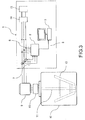
- a detection device 1 which performs the rotary speed and rotary torque detection method of the rotating shaft of the induction motor and the viscosity detection method of reaction liquid according to the present embodiment is described as an example with accompanying of FIG. 3 .
- the detection device 1 detects the rotary speed of the agitation blade 13 rotationally driven by the induction motor 9 when the reaction liquid supplied into the reaction vessel 12 is agitated in the reaction vessel.
- the reaction liquid can be a chemical reaction product.
- the detection device 1 includes a measurement unit 2 and a calculation processing unit 5.
- a power meter of three-phase alternating circuit, a 4-channel voltage meter, a 4-channel current meter and a frequency meter are incorporated into one unit and packaged to form the measurement unit 2, wherein the measurement unit 2 is connected to the three-phase alternating circuit through voltage lead-in wires 6 and current lead-in wires 7. Additionally, the measurement unit 2 can also be formed by each of the measurement instruments being individually disposed.
- the induction motor 9 which is the power source of the agitation blade 13 is assumed to be a three-phase circuit, and a commonly used power meter of three-phase can be used.
- the voltage and current are measured in each phase; thus, the rotary speed and rotary torque of the induction motor can be calculated at each phase and then combined.
- the present invention can also be applied to the case that the induction motor is a single-layer circuit or the direct current (DC) motor is driven by a DC power.
- the calculation processing unit 5 includes a personal computer, for example.
- the power, the voltage, the current and the frequency are first measured in the measurement unit 2 by the control of the action of the measurement unit 2, and then the calculation processing is performed for obtaining the rotary speed and rotary torque of the rotating shaft of the induction motor. Then, the calculation processing unit 5 performs the calculation processing for obtaining the viscosity of the reaction liquid based on the results.
- the measurement of each of the measurement instruments are performed synchronously with the command from the calculation processing unit 5 through the communication cables 8.
- the calculation processing unit 5 maintains the program for executing the calculation processing to obtain the rotary speed and rotary torque of the rotating shaft of the induction motor and the viscosity of reaction liquid, and the information required for calculation processing of the specific loss of the induction motor 9.
- the calculation processing unit 5 performs the calculation processing for the rotary speed of the rotating shaft of the induction motor based on the measurement information, and outputs the results through the screen or the internal information recording unit.
- the induction motor 9 is connected with the agitation shaft 11 through the speed reducer 10, wherein agitation blades 13 are mounted on the agitation shaft 11.
- the agitation blades 13 are disposed in the reaction vessel 12 and agitates the reactant supplied into the reaction vessel 12 along with the rotation of the rotating shaft of the induction motor 9.
- the induction motor 9 is provided with a power through the inverter 14 by the three-phase power source 15.
- the operator can observe the values of rotary speed and rotary torque of the rotating shaft of the induction motor and viscosity of reaction liquid displayed on the monitoring screen of the calculation processing unit 5 in real time.
- winding wire resistance is used to obtain the primary copper loss and the value of winding wire resistance is provided at the reference temperature (20 ⁇ ). Therefore, when the primary copper loss is calculated, by compensating the temperature to the actual operating temperature, the detection accuracy of the rotary speed and rotary torque of the rotating shaft of the induction motor and the viscosity of the reaction liquid can be improved.
- the value 234.5 is known as the temperature coefficient of resistance of copper. Since it is difficult to directly measure the winding wire temperature during rotation, the temperature detection unit is fixed and disposed at a location which represents the entire temperature of the internal of the motor, and the resulting value can be considered approximately as the primary and secondary winding wire temperature.
- the torque obtained according to Equation (10) includes the torque generated by the mechanical friction of reducer and bearings even when there is nothing in the reaction vessel (hereinafter it is called a null torque).
- a null torque the torque generated by the mechanical friction of reducer and bearings even when there is nothing in the reaction vessel.
- the null torque under the adopted agitating speed during the manufacturing of the reaction product is detected in advance and set to be a constant value, and the constant value is subtracted from the detected torque value when the viscosity is obtained by Equation (11), then the detection accuracy of viscosity can be improved.
- the reaction vessel since the reaction temperature is determined by each product, the reaction vessel has a temperature control function. Though compensation is unnecessary when the effect of viscosity of temperature control error can be neglected, actually the error of ⁇ 1 to ⁇ 3°C is inevitable. Therefore, in the present invention, in order to obtain the specific viscosity value of the reaction liquid at the predetermined temperature, by disposing a temperature detection device for detecting the reaction liquid temperature inside the reactor and a temperature compensation unit for compensating the viscosity value of the reaction liquid based on the temperature value obtained by the temperature detection device, the compensated value of viscosity at the particular predetermined temperature can be output.
- the temperature compensation of viscosity of reaction product is described in detail as follows.
- temperature characteristic In the process of temperature compensation of viscosity of reaction product, in advance, the relationship between the viscosity and the temperature of the reaction product (temperature characteristic) is clearly understood.
- the temperature characteristic is described as a graph shown in FIG. 4 .
- To represents the standard temperature when the reaction liquid is manufactured.
- the vertical axis represents the relative values at different temperatures of the value at temperature To of viscosity which is obtained by the method of the present invention and set to be 100 (hereinafter viscosity %).
- the viscosity measurement instrument such as Gardner Holdt method to measure the temperature characteristic of the viscosity of reaction liquid in advance, and then based on the result, the curve can be created.
- Compensating the viscosity of the reaction product is performed as follows.
- the temperature curve shown in FIG. 4 is stored in advance in the memory of a PC of the aforementioned (5) in a second or third order polynomial form.
- the viscosity at the standard temperature 100 is divided by the value of viscosity % obtained by the temperature measurement instrument, and the result (hereinafter temperature compensation coefficient) is multiplied by the value obtained by Equation (11).
- the type of polynomial is not limited as long as the error of the relationship between the viscosity and the temperature represents the minimum.
- the temperature compensation coefficient becomes 1; thus, the value may not change when it is multiplied by the value obtained by Equation (11).
- the temperature compensation coefficient becomes greater than 1.
- the supply amount compensation can be performed by compensating the viscosity value of the reaction liquid based on the difference between those two supply amounts.
- the supply amount refers to the supply mass or the supply volume, but generally the supply amount refers to the supply mass.
- the manufacturing of reaction product is to supply the raw materials into the reactor 12 according to requirements of customers and production schedule and so on, but the production amount of the production per unit is not constant.
- the rotary torque of the rotating shaft of the induction motor obtained by Equation (10) may be increased or decreased.
- the viscosity of reaction product obtained according to Equation (11) may be increased or decreased; thus, the value of specific viscosity of reaction liquid cannot be uniquely determined.
- the supply amount compensation is performed as follows. In advance, the relationship between the supply amount of the reaction product and the viscosity is clearly understood. The relationship is described as the graph shown in FIG. 5 .
- the graph can be obtained by actually measuring the viscosity by varying the supply amount, and can also be obtained by using a CAE (computer aided engineering) simulation.
- the vertical axis represents the relative values of the viscosity obtained according to the method of present invention at other supply amounts which are different than the standard supply amount W 0 at which the value is 100 (hereinafter viscosity %).
- the supply amount compensation is performed as follows.
- the curve shown in FIG. 5 is stored in advance in the memory of PC of the aforementioned (5) in a second or third order polynomial form.
- the value 100 is divided by the value of viscosity % of the supply amount at the production process, and the result (hereinafter supply amount compensation coefficient) is multiplied by the value obtained by Equation (11).
- the type of polynomial is not limited as long as the error of the relationship between the viscosity and the temperature represents the minimum.
- the supply amount compensation coefficient becomes 1, and thus the value may not change when it is multiplied by the value obtained by Equation (11).
- the supply amount W' is greater than the standard supply amount W 0
- the value of viscosity % ⁇ ' becomes greater than the value 100 obtained according to the curve of FIG. 5
- the supply amount compensation coefficient becomes smaller than 1.
- the endpoint of reaction determining unit determines the detected viscosity of the reaction liquid calculated according to the above mentioned unit is the endpoint of the reaction when the detected viscosity exceeds a predetermined value.
- the manufacturing method for manufacturing the reaction product specifically includes the following processes.
- the viscosity of the reaction product varies with the reaction process.
- the reaction is performed inside a reactor which performs the agitation of the reaction product by the rotation of the rotating shaft of an induction motor which is used as a power source and having agitation blades.
- Step I the loss power when the power input P of the induction motor is supplied is set to be P L , and the loss power P L is divided into a non-depending loss power A which does not depend on the rotary speed of the rotating shaft of the induction motor and a depending loss power B which depends on the rotary speed.
- the difference between the power input P and the loss power A is considered as the first order approximation value of the mechanical output of the induction motor PM 1
- Step II The loss power B 1 is obtained based on the first order approximation value N 1 .
- the first process is for detecting the rotary speed by using the rotary speed detection method of the rotating shaft of the induction motor including step I, step II and step III.
- the third process is for obtaining the viscosity ⁇ of the reaction product by using the following equation from the rotary torque T obtained from the detection process of the rotary torque.
- ⁇ ⁇ T/N (unit Pa ⁇ s, ⁇ is the constant determined according to the dimensions of the agitation blade and the reaction vessel used to agitate the reaction liquid.)
- a reaction product whose viscosity is increased such as resin
- a reaction product whose viscosity is reduced can also be manufactured by sealing the functional groups of the resin, such as the carboxyl group and the hydroxyl group, by using the compound having group which reacts with those functional groups (e.g., epoxy resin, carboxyl group, and the like).
- the reaction product includes synthetic resin, polymerizable monomer, and the like.
- the polymerized resin for example, includes polyethylene, polypropylene, polyvinyl chloride, polyvinylidene chloride resin, ABS (acrylonitrile butadiene-styrene resin) resin, polystyrene, acrylic resin, polyvinyl alcohol, epoxy resin, polyester resin, phenol resin, and polyurethane resin.
- ABS resin as a reaction product is manufactured, butadiene, styrene or acrylonitrile as a raw material is used, and various reactions such as emulsion polymerization process, bulk polymerization process, solution polymerization process and the like are performed inside the reactor in which the agitation of the reaction product is performed by using the rotation of the rotating shaft having agitation blades of the induction motor which serves as the power source.
- various reactions such as emulsion polymerization process, bulk polymerization process, solution polymerization process and the like are performed inside the reactor in which the agitation of the reaction product is performed by using the rotation of the rotating shaft having agitation blades of the induction motor which serves as the power source.
- viscosity of the reaction product can also be obtained by using the aforementioned processes.
- acrylic resin as a reaction product When acrylic resin as a reaction product is manufactured, acrylic monomer as a raw material is used, and the reaction of suspension polymerization process is performed inside the reactor in which the agitation of the reaction product is performed by using the rotation of the rotating shaft having agitation blades of the induction motor which serves as the power source. During the reaction process, viscosity of the reaction product can also be obtained by using the aforementioned processes.
- the acrylic monomer for example, includes (meth)acrylates such as methyl (meth)acrylate, ethyl (meth)acrylate, butyl (meth)acrylate, cyclohexyl (meth)acrylate, phenyl (meth)acrylate, benzyl (meth)acrylate, 2-ethylhexyl (meth)acrylate, 2-hydroxyethyl (meth)acrylate and the like, and polyfunctional (meth)acrylates such as ethylene glycol dimethacrylate, diethylene glycol dimethacrylate, neopentyl glycol dimethacrylate and the like.
- (meth)acrylates refer to acryl or methacryl.
- a common polymerization initiator in the polymerization of acrylic monomer, includes, for example, azo polymerization initiators such as 2,2'-azobis(2,4-dimethyl-4-methoxy valeronitrile), 2,2'-azobis(2,4-dimethyl valeronitrile), 2,2'-azobisisobutyronitrile, 2,2'-azobis(2-methylbutyronitrile), 2,2'-azobis[2-(2-imidazolin-2-yl)propane], dimethyl-2,2'-azobis(2-methylpropionate) and the like, and peroxide-based polymerization initiator such as bis(4-tert-butylcyclohexyl) peroxydicarbonate, di(2-ethylhexyl) peroxydicarbonate, di-n-propyl peroxydicarbonate, diisopropyl peroxydicarbonate, 1,1,3,3-tetramethylbutyl peroxyneodecano
- the compound having a phenolic hydroxyl group includes compound having hydroxyl group in the molecule of the reactant, for example, divalent phenol such as hydroquinone, resorcinol, catechol, dinaphthol and the like, bisphenols such as bisphenol A, bisphenol F, bisphenol S, bisphenol AD tetrabromobisphenol A and the like, biphenols such as biphenol tetramethyl biphenol and the like, phenols such as phenol novolak, cresol novolak, bisphenol A novolak, bisphenol F novolak and the like, and novolak resin obtained from formaldehyde, naphthols such as mononaphthol novolak, dinaphthol novolak, bis(2,7-dihydroxy naphthyl)-1,1-methane, (2-hydroxy naphthyl)-1-(2,7-dihydroxy
- the epihalohydrin includes epichlorohydrin, epibromohydrin, ⁇ -methyl epichlorohydrin and the like, for example.
- polyester resin as a reaction product When polyester resin as a reaction product is manufactured, polybasic acids and polyhydric alcohols as raw materials are used, and condensation of the above mentioned alcohols and acids is performed inside the reactor in which the agitation of the reaction product is performed by using the rotation of the rotating shaft having agitation blades of the induction motor which serves as the power source. During the reaction process, viscosity of the reaction product can also be obtained by using the aforementioned processes.
- the dicarboxylic acid in which polybasic acids are used includes aliphatic diprotic acid such as maleic acid, maleic acid anhydride, fumaric acid, itaconic acid, itaconic acid anhydride, oxalic acid, malonic acid, succinic acid, succinic acid anhydride, adipic acid, azelaic acid, sebacic acid, decane-1,10-dicarboxylic acid and the like, and aromatic or alicyclic diprotic acid such as phthalic acid, phthalic acid anhydride, tetrahydrophthalic acid and its anhydride, hexahydrophthalic acid and its anhydride, tetrabromophthalic acid and its anhydride, tetrachlorophthalic acid and its anhydride, chlorendic acid and its anhydride, himic acid and its anhydride, isophthalic acid, terephthalic acid, cyclohexane dicarboxylic acid, 2,6-n
- carboxylic acid having three or more carboxyl groups in one molecule and reactive derivatives thereof can be used and typically trimellitic acid anhydride, methylcyclohexene trimellitic acid, methylcyclohexene trimellitic acid anhydride, pyromellitic acid, pyromellitic dianhydride and the like are included.
- the polyhydric alcohols includes aliphatic diol such as polyalcohol, ethylene glycol, 1,2-propylene glycol, 1,4-butanediol, 1,5-pentanediol, 1,6-hexanediol, diethylene glycol, dipropylene glycol, triethylene glycol, neopentyl glycol and the like, bisphenol such as bisphenol A, bisphenol F and the like, hydrogenated bisphenol A such as ethylene oxide adduct of bisphenol A, propylene oxide adduct of bisphenol A, alkylene oxide adduct of bisphenol A, xylylene diglycol and cyclohexanedimethanol, alkylene glycol and alicyclic diol.
- bisphenol such as bisphenol A, bisphenol F and the like
- hydrogenated bisphenol A such as ethylene oxide adduct of bisphenol A, propylene oxide adduct of bisphenol A, alkylene oxide adduct of bisphenol A
- the polyhydric alcohols having three or more functional groups can use compounds having three or more hydroxyl groups typically including glycerine, trimethylolethane, trimethylolpropane, sorbitol, 1,2,3,6-hexanetetrole, 1,4-sorbitan, pentaerythritol, dipentaerythritol, 2-methyl propanetriol, 1,3,5-trihydroxybezene, tris(2-hydroxyethyl)isocyanurate and the like.
- compounds having three or more hydroxyl groups typically including glycerine, trimethylolethane, trimethylolpropane, sorbitol, 1,2,3,6-hexanetetrole, 1,4-sorbitan, pentaerythritol, dipentaerythritol, 2-methyl propanetriol, 1,3,5-trihydroxybezene, tris(2-hydroxyethyl)isocyanurate and the like.
- polyurethane resin as a reaction product When polyurethane resin as a reaction product is manufactured, polyisocyanate and polyol as raw materials are used, and polymerization of polyisocyanate and polyol is performed inside the reactor in which the agitation of the reaction product is performed by using the rotation of the rotating shaft having agitation blades of the induction motor which serves as the power source. During the reaction process, viscosity of the reaction product can also be obtained by using the aforementioned processes.
- the polyisocyanates includes aromatic diisocyanate compound such as p-phenylene diisocyanate, m-phenylene diisocyanate, p-xylene diisocyanate, m-xylene diisocyanate, 2,4-tolylene diisocyanate, 2,6-tolylene diisocyanate, 4,4'-diphenylmethane diisocyanate, 3,3'-dimethyldiphenyl-4,4'-diisocyanate, 3,3'-diethyldiphenyl-4,4'-diisocyanate, m-xylene diisocyanate, p-xylene diisocyanate, 1,3-bis( ⁇ , ⁇ -dimethyl isothiocyanatomethyl)benzene, tetramethyl xylene diisocyanate, diphenylene ether-4,4'-diisocyanate, naphthalene diisocyanate and the like, and aliphatic
- the polyol includes propylene glycol, ethylene glycol, glycerine, pentaerythritol and the like, for example.
- the device shown in FIG. 3 is used.
- the specification of the induction motor is as follows. Specification of a three-phase induction motor (Y connection) Capacity: 37 kW Rated speed: 1479 revolutions per min (rated slip 0.014) Rated voltage: 220V Rated current: 124A Rated frequency: 50 Hz Number of poles: 4 Primary winding wire resistance: 0.0328 ⁇ Primary winding wire reactance: 0.0446 ⁇ (at the rated frequency) Secondary winding wire resistance: 0.0130 ⁇ Secondary winding wire reactance: 0.0430 ⁇ (at the rated frequency) Resistance measurement reference temperature: 20°C Resistance temperature coefficient: 234.5 Mechanical loss: 160 W (at the rated speed) Iron loss: 465 W (hysteresis loss 230 W, eddy-current loss 235 W) Floating loss: 382 W Agitation blade speed reduction ratio: 29:1
- Example 1 Fabrication of urethane resin
- Diethylene glycol and toluene diisocyanate (2, 4 body: 2, 6 body at mass ratio of equal to or more than 95: equal to or less than 5) are used as raw materials of the urethane resin.
- diethylene glycol and toluene diisocyanate Since the reaction of diethylene glycol and toluene diisocyanate is an exothermic reaction, if toluene diisocyanate, which is the raw material, is put in at one time, an explosive reaction would occur. Therefore, diethylene glycol is put into the reaction vessel 12 shown in FIG. 1 in advance, and then in consideration of safety, toluene diisocyanate is divided into small portions and put in little by little to fabricate urethane resin.
- the standard supply amount of the reaction vessel 12 in the manufacturing process which is used in the present example is 5000 kg, and the supply amount of the present example is 4500 kg.
- the supply amount compensation coefficient obtained by the supply amount compensation curve is 1.09.
- the standard temperature during the reaction of the manufacturing process of the product is 80°C, and the reaction temperature in the example is 78°C.
- the temperature compensation coefficient at 78°C obtained by the temperature compensation curve of the product is 0.97.
- Clamp-on power meter CW240 (Yokogawa Meters & Instruments Corporation) is used as the measurement unit 2.
- the measurement instrument combines the power meter, 4-channel voltage meter, 4-channel current meter and frequency meter of three-phase alternating circuit and incorporates the four functions into a unit.
- Other measurement instruments beside the CW240 can also be used as long as having the same measurement functions.
- the calculation processing unit (PC) 5 obtains the data from the measurement unit 2 by the communication unit and has a calculation function for calculating the rotary speed and rotary torque of the rotating shaft of the induction motor by performing a predetermined calculation and a synchronous signal generating unit for generating a measurement timing signal synchronously corresponding to each of the measurement instruments.
- Each of the measurement instruments synchronously performs a predetermined number of times of measurement per unit time according to the command of the calculation processing unit 5, and then the calculation processing unit 5 captures the average value and the rotary speed and rotary torque are calculated.
- FIG. 6 shows a chart illustrating both the detected rotary speed (second approximation value N 2 shown as “1” in the figure) of the rotating shaft of the induction motor by employing the present invention and the actual rotary speed (shown as “2" in the figure).
- FIG. 7 shows a chart illustrating both the detected viscosity (shown as “1” in the figure) of reaction product (urethane resin) by employing the present invention and the detected viscosity (shown as "2" in the figure) of the reaction product by employing Patent reference 1. Especially, even though in the case that the rotary speed changes rapidly, the detected rotary speed follows the actual rotary speed.
- the difference between the detected rotary speed of the rotating shaft of the induction motor of the present example and the actual rotary speed is small, and it is known that the actual rotary speed is affected.
- the detected viscosity of the example has a sufficient accuracy on the detection of the relative change of the viscosity in the reaction process. Therefore, the objective of detecting the viscosity of urethane resin can be fully achieved by using the detection of the relative change of viscosity.
- rPa • s The relative viscosity displayed as rPa • s numerically includes specific values of the agitation system consisting of the induction motor, the speed reducer and the agitation blades; thus, if the agitation system is changed, these values will also be entirely increased or decreased. However, there is no trouble on the detection of the relative change of the viscosity in the system.
- the result of correlativity analysis of the viscosity of urethane resin detected in the example and the viscosity of urethane resin detected by the method of Patent reference 1 is shown in FIG. 8 .
- the linearity of the example is greater than the contribution ratio (the square of correlation coefficient) 0.999 and is extremely good.
- polyethylene terephthalate resin is fabricated in the same manner as Example 1 by using terephthalic acid and ethylene glycol and a common method.
- the correlation of the two viscosity values is very good and it is confirmed that polyester resin can be obtained by using the method of present invention.
- methyl methacrylate resin is fabricated in the same manner as Example 1 by using methyl methacrylate and a common method.
- the correlation of the two viscosity values is very good and it is confirmed that methyl methacrylate resin can be obtained by using the method of present invention.
- epoxy resin is fabricated in the same manner as Example 1 by using epichlorohydrine and bisphenol A and a common method.
- the correlation of the two viscosity values is very good and it is confirmed that epoxy resin can be obtained by using the method of present invention.
- the rotary speed shown in FIG. 4 is a second order approximation value
- the rotary speed of the rotating shaft of the induction motor of the present invention can be determined as a third order or more than the third order approximation value, and the rotary torque and viscosity can also be determined based on the resulting rotary speed.
- the to-be-detected object which is further detected by using the detected rotary speed is not limited to be the viscosity of the reaction product and can also applied to other applications.
Landscapes
- Physics & Mathematics (AREA)
- General Physics & Mathematics (AREA)
- Power Engineering (AREA)
- Engineering & Computer Science (AREA)
- General Health & Medical Sciences (AREA)
- Biochemistry (AREA)
- Analytical Chemistry (AREA)
- Chemical & Material Sciences (AREA)
- Immunology (AREA)
- Pathology (AREA)
- Life Sciences & Earth Sciences (AREA)
- Health & Medical Sciences (AREA)
- Control Of Ac Motors In General (AREA)
- Force Measurement Appropriate To Specific Purposes (AREA)
- Lubricants (AREA)
Claims (11)
- Erfassungsverfahren für eine Drehgeschwindigkeit einer Drehwelle eines Induktionsmotors (9), wobei das Erfassungsverfahren, wenn eine Leistungseingabe P dem Induktionsmotor (9) zugeführt wird, die Drehgeschwindigkeit der Drehwelle des Induktionsmotors (9) erfasst, wobei das Erfassungsverfahren umfasst:einen Schritt I, umfassend:wenn die Leistungseingabe P zugeführt wird, Einstellen, dass eine Verlustleistung PL beträgt, Aufteilen der Verlustleistung PL in eine nicht abhängige Verlustleistung A, welche nicht von der Drehgeschwindigkeit der Drehwelle des Induktionsmotors (9) abhängt, und eine abhängige Verlustleistung B, welche von der Drehgeschwindigkeit abhängt;Berücksichtigen einer Differenz zwischen der Leistungseingabe P und der nicht abhängigen Verlustleistung A als einen Näherungswert PM1 erster Ordnung einer mechanischen Ausgangsleistung des Induktionsmotors (9); undausgehend von einer Gleichung PM1 = αS1 (α ist eine Motorkonstante), wobei die Ausgangsleistung PM1 in dem Induktionsmotor (9) abgegeben wird und S1 ein Schlupf ist, Bestimmen eines Näherungswerts erster Ordnung der Drehgeschwindigkeit der Drehwelle durch N1 = NS(1 - S1) (Ns ist eine synchronisierte Geschwindigkeit);einen Schritt II, Bestimmen abhängig von dem Näherungswert erster Ordnung N1 der abhängigen Verlustleistung B1; undeinen Schritt III, umfassend:Berücksichtigen eines Näherungswerts zweiter Ordnung PM2 der Ausgangsleistung des Induktionsmotors (9) als P - (A + B1); undausgehend von einer Gleichung PM2 = αS2 (α ist die Motorkonstante), wobei die Ausgangsleistung PM2 in dem Induktionsmotor (9) abgegeben wird und S2 der Schlupf ist, Bestimmen eines Näherungswerts zweiter Ordnung der Drehgeschwindigkeit der Drehwelle als N2 = NS(1 - S2) (Ns ist die synchronisierte Geschwindigkeit).
- Erfassungsverfahren für eine Drehgeschwindigkeit einer Drehwelle eines Induktionsmotors (9) nach Anspruch 1, darüber hinaus umfassend ein Wiederholen eines Schritts IV und eines Schritts V eine vorbestimmte Anzahl oft, nachdem der Näherungswert zweiter Ordnung N2 durch den Schritt III bestimmt wurde,
wobei der Schritt IV ein Bestimmen einer Verlustleistung Bn abhängig von einem Näherungswert n-ter Ordnung Nn ist;
wobei der Schritt V umfasst:Berücksichtigen eines Näherungswerts (n + 1)-ter Ordnung PM(n+1) der Ausgangsleistung des Induktionsmotors als P - (A + B); undausgehend von einer Gleichung PM(n+1) = αS(n+1) (α ist die Motorkonstante), wobei die Ausgangsleistung PM(n+1) in dem Induktionsmotor (9) abgegeben wird und S(n+1) der Schlupf ist, Bestimmen eines Näherungswerts (n + 1)-ter Ordnung der Drehgeschwindigkeit der Drehwelle als N(n+1) = NS(1 - S(n+1)) (Ns ist die synchronisierte Geschwindigkeit, n ist eine ganze Zahl gleich oder größer als 2). - Vorrichtung (1) zum Erfassen einer Drehgeschwindigkeit einer Drehwelle eines Induktionsmotors (9), wobei die Vorrichtung die Drehgeschwindigkeit der Drehwelle des Induktionsmotors (9) erfasst, wenn eine Leistungseingabe P dem Induktionsmotor (9) zugeführt wird, wobei die Vorrichtung (1) umfasst:eine Informationsbestimmungseinheit, um eine Messinformation zu bestimmen, welche eine Leistungseingabe P, einen Strom, eine Spannung und eine Spannungsfrequenz, welche dem Induktionsmotor (9) zugeführt werden, umfasst; undeine Berechnungsverarbeitungseinheit (5), um die Drehgeschwindigkeit der Drehwelle des Induktionsmotors (9) durch eine Rechnung abhängig von der Messinformation zu bestimmen,wobei die Berechnungsverarbeitungseinheit (5) ausgestaltet ist, um Prozesse auszuführen, welche in einem Erfassungsverfahren für die Drehgeschwindigkeit der Drehwelle des Induktionsmotors (9) definiert sind, wobei das Erfassungsverfahren umfasst:einen Schritt I, umfassend:wenn die Leistungseingabe P zugeführt wird, Einstellen, dass eine Verlustleistung PL beträgt, Aufteilen der Verlustleistung PL in eine nicht abhängige Verlustleistung A, welche nicht von der Drehgeschwindigkeit der Drehwelle des Induktionsmotors (9) abhängt, und eine abhängige Verlustleistung B, welche von der Drehgeschwindigkeit abhängt;Berücksichtigen einer Differenz zwischen der Leistungseingabe P und der nicht abhängigen Verlustleistung A als einen Näherungswert PM1 erster Ordnung einer mechanischen Ausgangsleistung des Induktionsmotors (9); undausgehend von einer Gleichung PM1 = αS1 (α ist eine Motorkonstante), wobei die Ausgangsleistung PM1 in dem Induktionsmotor (9) abgegeben wird und S1 ein Schlupf ist, Bestimmen eines Näherungswerts erster Ordnung der Drehgeschwindigkeit der Drehwelle durch N1 = NS(1 - S1) (Ns ist eine synchronisierte Geschwindigkeit);einen Schritt II, Bestimmen abhängig von dem Näherungswert erster Ordnung N1 der abhängigen Verlustleistung B1; undeinen Schritt III, umfassend:Berücksichtigen eines Näherungswerts zweiter Ordnung PM2 der Ausgangsleistung des Induktionsmotors (9) als P - (A + B1); undausgehend von einer Gleichung PM2 = αS2 (α ist die Motorkonstante), wobei die Ausgangsleistung PM2 in dem Induktionsmotor (9) abgegeben wird und S2 der Schlupf ist, Bestimmen eines Näherungswerts zweiter Ordnung der Drehgeschwindigkeit der Drehwelle als N2 = NS(1 - S2) (Ns ist die synchronisierte Geschwindigkeit).
- Vorrichtung (1) zum Erfassen einer Drehgeschwindigkeit einer Drehwelle eines Induktionsmotors (9) nach Anspruch 3, wobei die Berechnungsverarbeitungseinheit (5) darüber hinaus einen Schritt IV und einen Schritt V eine vorbestimmte Anzahl oft wiederholt, nachdem der Näherungswert zweiter Ordnung N2 durch den Schritt III bestimmt wurde,
wobei der Schritt IV ein Bestimmen einer Verlustleistung Bn abhängig von einem Näherungswert n-ter Ordnung Nn ist;
wobei der Schritt V umfasst:Berücksichtigen eines Näherungswerts (n + 1)-ter Ordnung PM(n+1) der Ausgangsleistung des Induktionsmotors als P - (A + B); undausgehend von einer Gleichung PM(n+1) = αS(n+1) (α ist die Motorkonstante), wobei die Ausgangsleistung PM(n+1) in dem Induktionsmotor (9) abgegeben wird und S(n+1) der Schlupf ist, Bestimmen eines Näherungswerts (n + 1)-ter Ordnung der Drehgeschwindigkeit der Drehwelle als N(n+1) = NS (1 - S(n+1)) (Ns ist die synchronisierte Geschwindigkeit, n ist eine ganze Zahl gleich oder größer als 2). - Erfassungsverfahren für ein Drehmoment einer Drehwelle eines Induktionsmotors (9), wobei das Erfassungsverfahren, wenn eine Leistungseingabe P dem Induktionsmotor (9) zugeführt wird, das Drehmoment der Drehwelle des Induktionsmotors (9) erfasst, wobei das Erfassungsverfahren des Drehmoments ein Erfassungsverfahren einer Drehgeschwindigkeit einer Drehwelle eines Induktionsmotors (9) nach Anspruch 1 umfasst,
wobei das Erfassungsverfahren des Drehmoments darüber hinaus umfasst:Bestimmen abhängig von der nicht abhängigen Verlustleistung A, der abhängigen Verlustleistung B1, welche von dem Schritt II bestimmt wird, und dem Näherungswert zweiter Ordnung N2 der Drehgeschwindigkeit, welcher von dem Schritt III bestimmt wird, des Drehmoments T, wobei eine Gleichung
- Vorrichtung (1) zum Erfassen eines Drehmoments einer Drehwelle eines Induktionsmotors (9), wobei die Vorrichtung das Drehmoment der Drehwelle des Induktionsmotors (9) erfasst, wenn eine Leistungseingabe P dem Induktionsmotors (9) zugeführt wird, wobei die Vorrichtung zum Erfassen des Drehmoments eine Vorrichtung zum Erfassen einer Drehgeschwindigkeit nach Anspruch 3 umfasst,
wobei die Berechnungsverarbeitungseinheit (5) darüber hinaus ausgestaltet ist, um das Drehmoment der Drehwelle des Induktionsmotors (9) durch eine Berechnung abhängig von der Messinformation zu bestimmen,
wobei die Berechnungsverarbeitungseinheit (5) eine Berechnung abhängig von der nicht abhängigen Verlustleistung A, der abhängigen Verlustleistung B1, welche durch den Schritt II bestimmt wird, und dem Näherungswert zweiter Ordnung N2 der Drehgeschwindigkeit, welcher von dem Schritt III bestimmt wird, ausführt, wobei eine Gleichung
- Erfassungsverfahren für eine Viskosität einer Reaktionsflüssigkeit, wobei das Erfassungsverfahren ausgestaltet ist, um die Viskosität der Reaktionsflüssigkeit zu erfassen, wenn die Reaktionsflüssigkeit durch eine Drehung einer Drehwelle mit einem Rührflügel (13) eines Induktionsmotors (9), welcher als eine Leistungsquelle dient, gerührt wird, wobei das Erfassungsverfahren für die Viskosität der Reaktionsflüssigkeit umfasst:ein Erfassungsverfahren für die Drehgeschwindigkeit der Drehwelle des Induktionsmotors (9) nach Anspruch 1,wobei das Erfassungsverfahren für die Viskosität der Reaktionsflüssigkeit darüber hinaus umfasst:Bestimmen eines Drehmoments T der Drehwelle, wobei eine Gleichung
 Ordnung N2 der Drehgeschwindigkeit, welcher von dem Schritt III bestimmt wird, verwendet wird; undBestimmen von dem Drehmoment T der Viskosität η, wobei eine Gleichung
- Vorrichtung (1) zum Erfassen einer Viskosität einer Reaktionsflüssigkeit, wobei die Vorrichtung in einem Reaktionsbehälter (12) angeordnet ist, welcher die Reaktionsflüssigkeit durch eine Drehung einer Drehwelle mit einem Rührflügel (13) eines Induktionsmotors (9), welcher als eine Leistungsquelle dient, rührt, wobei die Vorrichtung (1) umfasst
eine Vorrichtung (1) zum Erfassen einer Drehgeschwindigkeit der Drehwelle des Induktionsmotors (9) nach Anspruch 3,
wobei die Berechnungsverarbeitungseinheit (5) darüber hinaus ausgestaltet ist, um die Viskosität der Reaktionsflüssigkeit abhängig von der Messinformation zu bestimmen,
wobei die Berechnungsverarbeitungseinheit (5) eine Berechnung abhängig von der nicht abhängigen Verlustleistung A, der abhängigen Verlustleistung B1, welche von dem Schritt II bestimmt wird, und dem Näherungswert zweiter Ordnung N2 der Drehgeschwindigkeit, welcher von dem Schritt III bestimmt wird, ausführt, wobei eine Gleichung
wobei die Berechnungsverarbeitungseinheit ausgehend von dem bestimmten Drehmoment T eine Berechnung der Viskosität η durchführt, wobei eine Gleichung
- Herstellungsverfahren für ein Reaktionsprodukt, wobei mindestens eine Art einer Verbindung als ein Rohmaterial eingesetzt wird und in einem Reaktionsprozess das Rohmaterial hergestellt wird, wobei das Reaktionsprodukt, dessen Viskosität mit dem Reaktionsprozess variiert, hergestellt wird, und
wobei die Reaktion innerhalb eines Reaktionsbehälters (12) ausgeführt wird, welcher das Reaktionsprodukt durch eine Drehung einer Drehwelle mit einem Rührflügel (13) eines Induktionsmotors (9), der während der Reaktion als eine Energiequelle eingesetzt wird, rührt, wobei das Herstellungsverfahren umfasst:einen ersten Prozess, welcher eine Drehgeschwindigkeit der Drehwelle des Induktionsmotors (9) mittels eines Verfahrens zum Erfassen der Drehgeschwindigkeit nach Anspruch 1 erfasst,einen zweiten Prozess, welcher ein Drehmoment der Drehwelle des Induktionsmotors (9) mittels eines Verfahrens zum Erfassen des Drehmoments erfasst, umfassend:Bestimmen eines Drehmoments T, wobei eine Gleichung einen dritten Prozess, welcher eine Viskosität des Reaktionsprodukts bestimmt, umfassend:ausgehend von dem Drehmoment T, welches durch einen Erfassungsprozess der Drehgeschwindigkeit erfasst wird, Bestimmen der Viskosität η, wobei eine Gleichung
- Herstellungsverfahren eines Reaktionsprodukts nach Anspruch 9, wobei das Reaktionsprodukt ein Harz ist.
- Herstellungsverfahren eines Reaktionsprodukts nach Anspruch 10, wobei das Harz eine oder mehrere Arten eines Harzes ist, welche ausgewählt sind aus der Gruppe, die aus einem Epoxyharz, einem Polyurethanharz, einem Polyesterharz und einem Acrylharz besteht.
Applications Claiming Priority (2)
| Application Number | Priority Date | Filing Date | Title |
|---|---|---|---|
| JP2010289597 | 2010-12-27 | ||
| PCT/JP2011/078673 WO2012090686A1 (ja) | 2010-12-27 | 2011-12-12 | 回転速度検出方法及びその装置、反応液粘度検出方法及びその装置、並びに反応生成物の製造方法 |
Publications (3)
| Publication Number | Publication Date |
|---|---|
| EP2660609A1 EP2660609A1 (de) | 2013-11-06 |
| EP2660609A4 EP2660609A4 (de) | 2014-10-22 |
| EP2660609B1 true EP2660609B1 (de) | 2016-03-16 |
Family
ID=46382803
Family Applications (1)
| Application Number | Title | Priority Date | Filing Date |
|---|---|---|---|
| EP11853581.4A Not-in-force EP2660609B1 (de) | 2010-12-27 | 2011-12-12 | Drehzahlerkennungsverfahren und vorrichtung dafür, verfahren zur erkennung der viskosität einer reaktionsflüssigkeit und vorrichtung dafür sowie verfahren zur herstellung eines reaktionsprodukts |
Country Status (7)
| Country | Link |
|---|---|
| US (1) | US8781761B2 (de) |
| EP (1) | EP2660609B1 (de) |
| JP (1) | JP5051486B2 (de) |
| KR (1) | KR101376355B1 (de) |
| CN (1) | CN103124908B (de) |
| MY (1) | MY156605A (de) |
| WO (1) | WO2012090686A1 (de) |
Families Citing this family (11)
| Publication number | Priority date | Publication date | Assignee | Title |
|---|---|---|---|---|
| JP5168609B2 (ja) * | 2011-06-30 | 2013-03-21 | Dic株式会社 | 反応液の粘度を検知する方法、反応液の粘度検知装置、反応生成物を得る方法及び反応生成物を得るための製造装置 |
| US9851286B2 (en) * | 2012-03-13 | 2017-12-26 | Vibrac, Llc | Viscosity testing system and method of using the same |
| JP5817624B2 (ja) * | 2012-03-30 | 2015-11-18 | Dic株式会社 | 印刷インキワニス用樹脂溶液の生成方法、及び生成装置 |
| JP6024344B2 (ja) * | 2012-09-27 | 2016-11-16 | Dic株式会社 | 反応液の粘度検知方法及び装置並びに反応液の生成装置 |
| DE102012220482A1 (de) * | 2012-11-09 | 2014-05-15 | Wagner Vermögensverwaltungs-GmbH & Co. KG | Verfahren zur Steuerung eines Drehschraubers sowie Drehschrauber |
| US10254318B2 (en) * | 2013-05-29 | 2019-04-09 | Nidec Motor Corporation | Systems and methods for estimating input power of an electric motor |
| DE102015119756B3 (de) * | 2015-11-16 | 2016-11-17 | Sartorius Stedim Biotech Gmbh | Mischvorrichtung zum Durchmischen eines Bioreaktors aufweisend eine Synchronisierungseinrichtung |
| US20170373487A1 (en) * | 2016-09-08 | 2017-12-28 | Mojtaba Rashvand | Starting and protecting induction motors |
| JP7000374B2 (ja) * | 2019-04-19 | 2022-01-19 | 横河電機株式会社 | 粘性推定装置及び粘性推定方法 |
| CN112858102B (zh) * | 2021-02-22 | 2024-05-24 | 长江大学 | 一种钻井液粘度检测方法、装置及系统 |
| US12304318B2 (en) * | 2021-08-26 | 2025-05-20 | Hamilton Sundstrand Corporation | Motor speed measurement systems |
Family Cites Families (11)
| Publication number | Priority date | Publication date | Assignee | Title |
|---|---|---|---|---|
| US4532458A (en) * | 1980-09-26 | 1985-07-30 | National Research Development Corporation | Variable-speed electrical machines |
| US5057760A (en) * | 1985-01-31 | 1991-10-15 | Aeg Westinghouse Transportation Systems, Inc. | Torque determination for control of an induction motor apparatus |
| JPS63144795A (ja) | 1986-12-08 | 1988-06-16 | Toyota Autom Loom Works Ltd | 誘導電動機の速度制御装置 |
| JPS63249486A (ja) | 1987-04-03 | 1988-10-17 | Mitsubishi Heavy Ind Ltd | 誘導電動機二次抵抗演算装置 |
| JP3516216B2 (ja) | 1994-10-13 | 2004-04-05 | 新二 新中 | 誘導電動機駆動自動車のための速度検出方法及びその装置 |
| JPH10237181A (ja) * | 1997-02-28 | 1998-09-08 | Fuji Photo Film Co Ltd | 重合方法及び装置 |
| US6469469B1 (en) * | 2000-09-01 | 2002-10-22 | Spellman High Voltage Electronics Corp. | Variable output induction motor drive system |
| US6828751B2 (en) * | 2001-06-13 | 2004-12-07 | Emerson Electric Co. | Induction motor control system |
| US6640617B2 (en) * | 2001-08-16 | 2003-11-04 | Levitronix Llc | Apparatus and a method for determining the viscosity of a fluid |
| WO2009151156A1 (en) * | 2008-06-13 | 2009-12-17 | Miao-Miao Cheng | A stand-alone power system by using a flywheel induction motor |
| JP4883142B2 (ja) | 2008-07-04 | 2012-02-22 | Dic株式会社 | 反応液粘度測定装置及び反応液製造装置、並びに反応液製造方法 |
-
2011
- 2011-12-12 EP EP11853581.4A patent/EP2660609B1/de not_active Not-in-force
- 2011-12-12 JP JP2012504947A patent/JP5051486B2/ja active Active
- 2011-12-12 WO PCT/JP2011/078673 patent/WO2012090686A1/ja not_active Ceased
- 2011-12-12 CN CN201180046237.8A patent/CN103124908B/zh not_active Expired - Fee Related
- 2011-12-12 MY MYPI2013700460A patent/MY156605A/en unknown
- 2011-12-12 KR KR1020127027392A patent/KR101376355B1/ko not_active Expired - Fee Related
- 2011-12-12 US US13/823,110 patent/US8781761B2/en not_active Expired - Fee Related
Also Published As
| Publication number | Publication date |
|---|---|
| WO2012090686A1 (ja) | 2012-07-05 |
| KR101376355B1 (ko) | 2014-03-20 |
| JP5051486B2 (ja) | 2012-10-17 |
| CN103124908B (zh) | 2015-04-29 |
| KR20130007622A (ko) | 2013-01-18 |
| EP2660609A4 (de) | 2014-10-22 |
| EP2660609A1 (de) | 2013-11-06 |
| US20130172507A1 (en) | 2013-07-04 |
| CN103124908A (zh) | 2013-05-29 |
| US8781761B2 (en) | 2014-07-15 |
| MY156605A (en) | 2016-03-15 |
| JPWO2012090686A1 (ja) | 2014-06-05 |
Similar Documents
| Publication | Publication Date | Title |
|---|---|---|
| EP2660609B1 (de) | Drehzahlerkennungsverfahren und vorrichtung dafür, verfahren zur erkennung der viskosität einer reaktionsflüssigkeit und vorrichtung dafür sowie verfahren zur herstellung eines reaktionsprodukts | |
| JP4883142B2 (ja) | 反応液粘度測定装置及び反応液製造装置、並びに反応液製造方法 | |
| TW201233041A (en) | Method and system for determining deterioration of permanent magnets of electric apparatus | |
| Jung et al. | Vibration and current dataset of three-phase permanent magnet synchronous motors with stator faults | |
| Gobbi et al. | Experimental investigations on computer-based methods for determination of static electromagnetic characteristics of switched reluctance motors | |
| JP2011133312A (ja) | 反応監視装置及び反応液製造装置、並びに反応液製造方法 | |
| JP6024344B2 (ja) | 反応液の粘度検知方法及び装置並びに反応液の生成装置 | |
| Yamamoto et al. | Torque estimation of variable-speed induction motors without torque and rotational speed meters | |
| JP5817624B2 (ja) | 印刷インキワニス用樹脂溶液の生成方法、及び生成装置 | |
| JP4631298B2 (ja) | 回転機の設計方法及び回転機の製造方法 | |
| JP2015200577A (ja) | 磁気特性測定装置及びその制御方法 | |
| EP3957975B1 (de) | Vorrichtung und verfahren zur viskositätsschätzung | |
| Herman et al. | Evaluation and uncertainties of an electric direct-drive motor test system with a mathematical model confirmation | |
| Silva et al. | Torque estimation using rotor slots harmonics on a three-phase induction motor | |
| Mzungu et al. | Application of induction machine efficiency testing standards in South Africa | |
| JP5407964B2 (ja) | 印刷インキワニス用樹脂溶液の生成方法 | |
| CN119827978A (zh) | 一种计算永磁电机的定子铁损的方法 | |
| CN118487531B (zh) | 一种电机永磁体温度确定方法及相关装置、存储介质 | |
| EP4701067A1 (de) | Verfahren zur identifikation von läufernutoberschwingungen in einem motorstromspektrum | |
| Concari et al. | Induction drive health assessment in DSP-based self-commissioning procedures | |
| Kurz et al. | Experimental study on boosting small electric drive systems in short-term operation | |
| Lamprokostopoulos et al. | Detection of Demagnetization Faults in Axial Flux Permanent-Magnet Synchronous Wind Generators. Energies 2022, 15, 3220 | |
| Kumar et al. | Formulation of Stray Loss in Medium Power Inverter-fed Induction Motors | |
| CN102636749A (zh) | 电动机参数的测量方法 | |
| Paula | Evaluating EPACT’s Impact |
Legal Events
| Date | Code | Title | Description |
|---|---|---|---|
| PUAI | Public reference made under article 153(3) epc to a published international application that has entered the european phase |
Free format text: ORIGINAL CODE: 0009012 |
|
| 17P | Request for examination filed |
Effective date: 20130311 |
|
| AK | Designated contracting states |
Kind code of ref document: A1 Designated state(s): AL AT BE BG CH CY CZ DE DK EE ES FI FR GB GR HR HU IE IS IT LI LT LU LV MC MK MT NL NO PL PT RO RS SE SI SK SM TR |
|
| DAX | Request for extension of the european patent (deleted) | ||
| A4 | Supplementary search report drawn up and despatched |
Effective date: 20140919 |
|
| RIC1 | Information provided on ipc code assigned before grant |
Ipc: H02P 29/00 20060101ALI20140915BHEP Ipc: H02P 21/14 20060101ALI20140915BHEP Ipc: G01N 11/14 20060101ALI20140915BHEP Ipc: H02P 6/18 20060101ALN20140915BHEP Ipc: G01P 3/44 20060101AFI20140915BHEP |
|
| RIC1 | Information provided on ipc code assigned before grant |
Ipc: G01P 3/44 20060101AFI20150806BHEP Ipc: H02P 29/00 20060101ALI20150806BHEP Ipc: H02P 6/18 20060101ALN20150806BHEP Ipc: H02P 21/14 20060101ALI20150806BHEP Ipc: G01N 11/14 20060101ALI20150806BHEP |
|
| GRAP | Despatch of communication of intention to grant a patent |
Free format text: ORIGINAL CODE: EPIDOSNIGR1 |
|
| INTG | Intention to grant announced |
Effective date: 20150921 |
|
| RIN1 | Information on inventor provided before grant (corrected) |
Inventor name: EBISAWA, SHOUEI |
|
| GRAS | Grant fee paid |
Free format text: ORIGINAL CODE: EPIDOSNIGR3 |
|
| GRAA | (expected) grant |
Free format text: ORIGINAL CODE: 0009210 |
|
| AK | Designated contracting states |
Kind code of ref document: B1 Designated state(s): AL AT BE BG CH CY CZ DE DK EE ES FI FR GB GR HR HU IE IS IT LI LT LU LV MC MK MT NL NO PL PT RO RS SE SI SK SM TR |
|
| REG | Reference to a national code |
Ref country code: GB Ref legal event code: FG4D |
|
| REG | Reference to a national code |
Ref country code: CH Ref legal event code: EP |
|
| REG | Reference to a national code |
Ref country code: IE Ref legal event code: FG4D |
|
| REG | Reference to a national code |
Ref country code: AT Ref legal event code: REF Ref document number: 781690 Country of ref document: AT Kind code of ref document: T Effective date: 20160415 |
|
| REG | Reference to a national code |
Ref country code: DE Ref legal event code: R096 Ref document number: 602011024184 Country of ref document: DE |
|
| REG | Reference to a national code |
Ref country code: NL Ref legal event code: FP |
|
| REG | Reference to a national code |
Ref country code: LT Ref legal event code: MG4D |
|
| PG25 | Lapsed in a contracting state [announced via postgrant information from national office to epo] |
Ref country code: FI Free format text: LAPSE BECAUSE OF FAILURE TO SUBMIT A TRANSLATION OF THE DESCRIPTION OR TO PAY THE FEE WITHIN THE PRESCRIBED TIME-LIMIT Effective date: 20160316 Ref country code: HR Free format text: LAPSE BECAUSE OF FAILURE TO SUBMIT A TRANSLATION OF THE DESCRIPTION OR TO PAY THE FEE WITHIN THE PRESCRIBED TIME-LIMIT Effective date: 20160316 Ref country code: GR Free format text: LAPSE BECAUSE OF FAILURE TO SUBMIT A TRANSLATION OF THE DESCRIPTION OR TO PAY THE FEE WITHIN THE PRESCRIBED TIME-LIMIT Effective date: 20160617 Ref country code: NO Free format text: LAPSE BECAUSE OF FAILURE TO SUBMIT A TRANSLATION OF THE DESCRIPTION OR TO PAY THE FEE WITHIN THE PRESCRIBED TIME-LIMIT Effective date: 20160616 |
|
| PG25 | Lapsed in a contracting state [announced via postgrant information from national office to epo] |
Ref country code: RS Free format text: LAPSE BECAUSE OF FAILURE TO SUBMIT A TRANSLATION OF THE DESCRIPTION OR TO PAY THE FEE WITHIN THE PRESCRIBED TIME-LIMIT Effective date: 20160316 Ref country code: LV Free format text: LAPSE BECAUSE OF FAILURE TO SUBMIT A TRANSLATION OF THE DESCRIPTION OR TO PAY THE FEE WITHIN THE PRESCRIBED TIME-LIMIT Effective date: 20160316 Ref country code: SE Free format text: LAPSE BECAUSE OF FAILURE TO SUBMIT A TRANSLATION OF THE DESCRIPTION OR TO PAY THE FEE WITHIN THE PRESCRIBED TIME-LIMIT Effective date: 20160316 Ref country code: LT Free format text: LAPSE BECAUSE OF FAILURE TO SUBMIT A TRANSLATION OF THE DESCRIPTION OR TO PAY THE FEE WITHIN THE PRESCRIBED TIME-LIMIT Effective date: 20160316 |
|
| PG25 | Lapsed in a contracting state [announced via postgrant information from national office to epo] |
Ref country code: PL Free format text: LAPSE BECAUSE OF FAILURE TO SUBMIT A TRANSLATION OF THE DESCRIPTION OR TO PAY THE FEE WITHIN THE PRESCRIBED TIME-LIMIT Effective date: 20160316 Ref country code: IS Free format text: LAPSE BECAUSE OF FAILURE TO SUBMIT A TRANSLATION OF THE DESCRIPTION OR TO PAY THE FEE WITHIN THE PRESCRIBED TIME-LIMIT Effective date: 20160716 Ref country code: EE Free format text: LAPSE BECAUSE OF FAILURE TO SUBMIT A TRANSLATION OF THE DESCRIPTION OR TO PAY THE FEE WITHIN THE PRESCRIBED TIME-LIMIT Effective date: 20160316 |
|
| PG25 | Lapsed in a contracting state [announced via postgrant information from national office to epo] |
Ref country code: SK Free format text: LAPSE BECAUSE OF FAILURE TO SUBMIT A TRANSLATION OF THE DESCRIPTION OR TO PAY THE FEE WITHIN THE PRESCRIBED TIME-LIMIT Effective date: 20160316 Ref country code: CZ Free format text: LAPSE BECAUSE OF FAILURE TO SUBMIT A TRANSLATION OF THE DESCRIPTION OR TO PAY THE FEE WITHIN THE PRESCRIBED TIME-LIMIT Effective date: 20160316 Ref country code: ES Free format text: LAPSE BECAUSE OF FAILURE TO SUBMIT A TRANSLATION OF THE DESCRIPTION OR TO PAY THE FEE WITHIN THE PRESCRIBED TIME-LIMIT Effective date: 20160316 Ref country code: SM Free format text: LAPSE BECAUSE OF FAILURE TO SUBMIT A TRANSLATION OF THE DESCRIPTION OR TO PAY THE FEE WITHIN THE PRESCRIBED TIME-LIMIT Effective date: 20160316 Ref country code: RO Free format text: LAPSE BECAUSE OF FAILURE TO SUBMIT A TRANSLATION OF THE DESCRIPTION OR TO PAY THE FEE WITHIN THE PRESCRIBED TIME-LIMIT Effective date: 20160316 Ref country code: PT Free format text: LAPSE BECAUSE OF FAILURE TO SUBMIT A TRANSLATION OF THE DESCRIPTION OR TO PAY THE FEE WITHIN THE PRESCRIBED TIME-LIMIT Effective date: 20160718 |
|
| REG | Reference to a national code |
Ref country code: DE Ref legal event code: R097 Ref document number: 602011024184 Country of ref document: DE |
|
| REG | Reference to a national code |
Ref country code: FR Ref legal event code: PLFP Year of fee payment: 6 |
|
| PG25 | Lapsed in a contracting state [announced via postgrant information from national office to epo] |
Ref country code: BE Free format text: LAPSE BECAUSE OF FAILURE TO SUBMIT A TRANSLATION OF THE DESCRIPTION OR TO PAY THE FEE WITHIN THE PRESCRIBED TIME-LIMIT Effective date: 20160316 Ref country code: IT Free format text: LAPSE BECAUSE OF FAILURE TO SUBMIT A TRANSLATION OF THE DESCRIPTION OR TO PAY THE FEE WITHIN THE PRESCRIBED TIME-LIMIT Effective date: 20160316 |
|
| PLBE | No opposition filed within time limit |
Free format text: ORIGINAL CODE: 0009261 |
|
| STAA | Information on the status of an ep patent application or granted ep patent |
Free format text: STATUS: NO OPPOSITION FILED WITHIN TIME LIMIT |
|
| PG25 | Lapsed in a contracting state [announced via postgrant information from national office to epo] |
Ref country code: DK Free format text: LAPSE BECAUSE OF FAILURE TO SUBMIT A TRANSLATION OF THE DESCRIPTION OR TO PAY THE FEE WITHIN THE PRESCRIBED TIME-LIMIT Effective date: 20160316 |
|
| 26N | No opposition filed |
Effective date: 20161219 |
|
| PG25 | Lapsed in a contracting state [announced via postgrant information from national office to epo] |
Ref country code: BG Free format text: LAPSE BECAUSE OF FAILURE TO SUBMIT A TRANSLATION OF THE DESCRIPTION OR TO PAY THE FEE WITHIN THE PRESCRIBED TIME-LIMIT Effective date: 20160616 |
|
| PG25 | Lapsed in a contracting state [announced via postgrant information from national office to epo] |
Ref country code: SI Free format text: LAPSE BECAUSE OF FAILURE TO SUBMIT A TRANSLATION OF THE DESCRIPTION OR TO PAY THE FEE WITHIN THE PRESCRIBED TIME-LIMIT Effective date: 20160316 |
|
| REG | Reference to a national code |
Ref country code: CH Ref legal event code: PL |
|
| PG25 | Lapsed in a contracting state [announced via postgrant information from national office to epo] |
Ref country code: MC Free format text: LAPSE BECAUSE OF FAILURE TO SUBMIT A TRANSLATION OF THE DESCRIPTION OR TO PAY THE FEE WITHIN THE PRESCRIBED TIME-LIMIT Effective date: 20160316 |
|
| REG | Reference to a national code |
Ref country code: IE Ref legal event code: MM4A |
|
| PG25 | Lapsed in a contracting state [announced via postgrant information from national office to epo] |
Ref country code: LI Free format text: LAPSE BECAUSE OF NON-PAYMENT OF DUE FEES Effective date: 20161231 Ref country code: LU Free format text: LAPSE BECAUSE OF NON-PAYMENT OF DUE FEES Effective date: 20161212 Ref country code: CH Free format text: LAPSE BECAUSE OF NON-PAYMENT OF DUE FEES Effective date: 20161231 |
|
| PG25 | Lapsed in a contracting state [announced via postgrant information from national office to epo] |
Ref country code: IE Free format text: LAPSE BECAUSE OF NON-PAYMENT OF DUE FEES Effective date: 20161212 |
|
| REG | Reference to a national code |
Ref country code: FR Ref legal event code: PLFP Year of fee payment: 7 |
|
| PG25 | Lapsed in a contracting state [announced via postgrant information from national office to epo] |
Ref country code: HU Free format text: LAPSE BECAUSE OF FAILURE TO SUBMIT A TRANSLATION OF THE DESCRIPTION OR TO PAY THE FEE WITHIN THE PRESCRIBED TIME-LIMIT; INVALID AB INITIO Effective date: 20111212 Ref country code: CY Free format text: LAPSE BECAUSE OF FAILURE TO SUBMIT A TRANSLATION OF THE DESCRIPTION OR TO PAY THE FEE WITHIN THE PRESCRIBED TIME-LIMIT Effective date: 20160316 |
|
| PG25 | Lapsed in a contracting state [announced via postgrant information from national office to epo] |
Ref country code: MK Free format text: LAPSE BECAUSE OF FAILURE TO SUBMIT A TRANSLATION OF THE DESCRIPTION OR TO PAY THE FEE WITHIN THE PRESCRIBED TIME-LIMIT Effective date: 20160316 |
|
| PG25 | Lapsed in a contracting state [announced via postgrant information from national office to epo] |
Ref country code: MT Free format text: LAPSE BECAUSE OF NON-PAYMENT OF DUE FEES Effective date: 20161212 |
|
| PG25 | Lapsed in a contracting state [announced via postgrant information from national office to epo] |
Ref country code: TR Free format text: LAPSE BECAUSE OF FAILURE TO SUBMIT A TRANSLATION OF THE DESCRIPTION OR TO PAY THE FEE WITHIN THE PRESCRIBED TIME-LIMIT Effective date: 20160316 Ref country code: AL Free format text: LAPSE BECAUSE OF FAILURE TO SUBMIT A TRANSLATION OF THE DESCRIPTION OR TO PAY THE FEE WITHIN THE PRESCRIBED TIME-LIMIT Effective date: 20160316 |
|
| REG | Reference to a national code |
Ref country code: AT Ref legal event code: UEP Ref document number: 781690 Country of ref document: AT Kind code of ref document: T Effective date: 20160316 |
|
| PGFP | Annual fee paid to national office [announced via postgrant information from national office to epo] |
Ref country code: GB Payment date: 20181227 Year of fee payment: 9 |
|
| PGFP | Annual fee paid to national office [announced via postgrant information from national office to epo] |
Ref country code: DE Payment date: 20191126 Year of fee payment: 9 Ref country code: NL Payment date: 20191114 Year of fee payment: 9 |
|
| PGFP | Annual fee paid to national office [announced via postgrant information from national office to epo] |
Ref country code: FR Payment date: 20191115 Year of fee payment: 9 |
|
| PGFP | Annual fee paid to national office [announced via postgrant information from national office to epo] |
Ref country code: AT Payment date: 20191125 Year of fee payment: 9 |
|
| GBPC | Gb: european patent ceased through non-payment of renewal fee |
Effective date: 20191212 |
|
| PG25 | Lapsed in a contracting state [announced via postgrant information from national office to epo] |
Ref country code: GB Free format text: LAPSE BECAUSE OF NON-PAYMENT OF DUE FEES Effective date: 20191212 |
|
| REG | Reference to a national code |
Ref country code: DE Ref legal event code: R119 Ref document number: 602011024184 Country of ref document: DE |
|
| REG | Reference to a national code |
Ref country code: NL Ref legal event code: MM Effective date: 20210101 |
|
| REG | Reference to a national code |
Ref country code: AT Ref legal event code: MM01 Ref document number: 781690 Country of ref document: AT Kind code of ref document: T Effective date: 20201212 |
|
| PG25 | Lapsed in a contracting state [announced via postgrant information from national office to epo] |
Ref country code: NL Free format text: LAPSE BECAUSE OF NON-PAYMENT OF DUE FEES Effective date: 20210101 |
|
| PG25 | Lapsed in a contracting state [announced via postgrant information from national office to epo] |
Ref country code: FR Free format text: LAPSE BECAUSE OF NON-PAYMENT OF DUE FEES Effective date: 20201231 Ref country code: AT Free format text: LAPSE BECAUSE OF NON-PAYMENT OF DUE FEES Effective date: 20201212 |
|
| PG25 | Lapsed in a contracting state [announced via postgrant information from national office to epo] |
Ref country code: DE Free format text: LAPSE BECAUSE OF NON-PAYMENT OF DUE FEES Effective date: 20210701 |