EP2659843A2 - Surgical forceps - Google Patents
Surgical forceps Download PDFInfo
- Publication number
- EP2659843A2 EP2659843A2 EP20130166210 EP13166210A EP2659843A2 EP 2659843 A2 EP2659843 A2 EP 2659843A2 EP 20130166210 EP20130166210 EP 20130166210 EP 13166210 A EP13166210 A EP 13166210A EP 2659843 A2 EP2659843 A2 EP 2659843A2
- Authority
- EP
- European Patent Office
- Prior art keywords
- jaw members
- flange
- jaw
- another
- components
- Prior art date
- Legal status (The legal status is an assumption and is not a legal conclusion. Google has not performed a legal analysis and makes no representation as to the accuracy of the status listed.)
- Granted
Links
Images




Classifications
-
- A—HUMAN NECESSITIES
- A61—MEDICAL OR VETERINARY SCIENCE; HYGIENE
- A61B—DIAGNOSIS; SURGERY; IDENTIFICATION
- A61B18/00—Surgical instruments, devices or methods for transferring non-mechanical forms of energy to or from the body
- A61B18/04—Surgical instruments, devices or methods for transferring non-mechanical forms of energy to or from the body by heating
- A61B18/12—Surgical instruments, devices or methods for transferring non-mechanical forms of energy to or from the body by heating by passing a current through the tissue to be heated, e.g. high-frequency current
- A61B18/14—Probes or electrodes therefor
- A61B18/1442—Probes having pivoting end effectors, e.g. forceps
- A61B18/1445—Probes having pivoting end effectors, e.g. forceps at the distal end of a shaft, e.g. forceps or scissors at the end of a rigid rod
-
- A—HUMAN NECESSITIES
- A61—MEDICAL OR VETERINARY SCIENCE; HYGIENE
- A61B—DIAGNOSIS; SURGERY; IDENTIFICATION
- A61B17/00—Surgical instruments, devices or methods
- A61B17/28—Surgical forceps
- A61B17/2812—Surgical forceps with a single pivotal connection
- A61B17/2816—Pivots
-
- A—HUMAN NECESSITIES
- A61—MEDICAL OR VETERINARY SCIENCE; HYGIENE
- A61B—DIAGNOSIS; SURGERY; IDENTIFICATION
- A61B18/00—Surgical instruments, devices or methods for transferring non-mechanical forms of energy to or from the body
- A61B18/04—Surgical instruments, devices or methods for transferring non-mechanical forms of energy to or from the body by heating
- A61B18/12—Surgical instruments, devices or methods for transferring non-mechanical forms of energy to or from the body by heating by passing a current through the tissue to be heated, e.g. high-frequency current
- A61B18/14—Probes or electrodes therefor
- A61B18/1442—Probes having pivoting end effectors, e.g. forceps
-
- A—HUMAN NECESSITIES
- A61—MEDICAL OR VETERINARY SCIENCE; HYGIENE
- A61B—DIAGNOSIS; SURGERY; IDENTIFICATION
- A61B17/00—Surgical instruments, devices or methods
- A61B17/28—Surgical forceps
- A61B17/285—Surgical forceps combined with cutting implements
-
- A—HUMAN NECESSITIES
- A61—MEDICAL OR VETERINARY SCIENCE; HYGIENE
- A61B—DIAGNOSIS; SURGERY; IDENTIFICATION
- A61B17/00—Surgical instruments, devices or methods
- A61B17/28—Surgical forceps
- A61B17/29—Forceps for use in minimally invasive surgery
-
- A—HUMAN NECESSITIES
- A61—MEDICAL OR VETERINARY SCIENCE; HYGIENE
- A61B—DIAGNOSIS; SURGERY; IDENTIFICATION
- A61B17/00—Surgical instruments, devices or methods
- A61B17/28—Surgical forceps
- A61B17/29—Forceps for use in minimally invasive surgery
- A61B2017/2947—Pivots
-
- A—HUMAN NECESSITIES
- A61—MEDICAL OR VETERINARY SCIENCE; HYGIENE
- A61B—DIAGNOSIS; SURGERY; IDENTIFICATION
- A61B18/00—Surgical instruments, devices or methods for transferring non-mechanical forms of energy to or from the body
- A61B2018/00571—Surgical instruments, devices or methods for transferring non-mechanical forms of energy to or from the body for achieving a particular surgical effect
- A61B2018/00607—Coagulation and cutting with the same instrument
-
- A—HUMAN NECESSITIES
- A61—MEDICAL OR VETERINARY SCIENCE; HYGIENE
- A61B—DIAGNOSIS; SURGERY; IDENTIFICATION
- A61B18/00—Surgical instruments, devices or methods for transferring non-mechanical forms of energy to or from the body
- A61B2018/00571—Surgical instruments, devices or methods for transferring non-mechanical forms of energy to or from the body for achieving a particular surgical effect
- A61B2018/0063—Sealing
-
- A—HUMAN NECESSITIES
- A61—MEDICAL OR VETERINARY SCIENCE; HYGIENE
- A61B—DIAGNOSIS; SURGERY; IDENTIFICATION
- A61B18/00—Surgical instruments, devices or methods for transferring non-mechanical forms of energy to or from the body
- A61B18/04—Surgical instruments, devices or methods for transferring non-mechanical forms of energy to or from the body by heating
- A61B18/12—Surgical instruments, devices or methods for transferring non-mechanical forms of energy to or from the body by heating by passing a current through the tissue to be heated, e.g. high-frequency current
- A61B18/14—Probes or electrodes therefor
- A61B18/1442—Probes having pivoting end effectors, e.g. forceps
- A61B2018/1452—Probes having pivoting end effectors, e.g. forceps including means for cutting
- A61B2018/1455—Probes having pivoting end effectors, e.g. forceps including means for cutting having a moving blade for cutting tissue grasped by the jaws
Definitions
- the present disclosure relates to surgical instruments and, more particularly, to an open surgical forceps for grasping, sealing, and/or dividing tissue, and methods of manufacturing thereof.
- a forceps is a plier-like instrument which relies on mechanical action between its jaws to grasp, clamp and constrict vessels or tissue. Electrosurgical forceps utilize both mechanical clamping action and electrical energy to affect hemostasis by heating tissue and blood vessels to coagulate and/or cauterize tissue. Certain surgical procedures require more than simply cauterizing tissue and rely on the unique combination of clamping pressure, precise electrosurgical energy control and gap distance (i.e., distance between opposing jaw members when closed about tissue) to "seal" tissue, vessels and certain vascular bundles.
- distal refers to the portion that is being described which is further from a user
- proximal refers to the portion that is being described which is closer to a user
- a forceps in accordance with one aspect of the present disclosure, includes an end effector assembly having first and second jaw members.
- Each of the jaw members includes a proximal flange extending therefrom.
- the proximal flange of each jaw member defines a bifurcated configuration having first and second spaced-apart flange components.
- the first flange components of the jaw members are configured to pivotably engage one another via a first engagement portion and the second flange components of the jaw members are configured to pivotably engage one another via a second engagement portion independent of the first engagement.
- One or both of the jaw members is pivotable relative to the other about the first and second engagement portions between an open position and a closed position for grasping tissue therebetween.
- a guide member is provided that is configured for positioning between the proximal flanges of the first and second jaw members.
- the guide member may include one (or more) tabs extending transversely therefrom that is configured to operably engage one of the first and second engagement portions or some other means to retain the jaw members in engagement with one another.
- the present disclosure encompasses forceps without including such a guide member.
- the first flange component of each of the jaw members includes an aperture defined transversely therethrough.
- One of the first flange components also includes a boss disposed about the aperture thereof. The boss is configured for engagement within the aperture of the other first flange component for pivotably engaging the first flange components to one another.
- the second flange components may be similarly configured.
- At least one of the engagement portions is provided by engaging a boss and an aperture.
- the tab is configured for engagement within an aperture defined through the first flange component(s) (or the second flange component(s)) of the jaw members.
- the tab may be configured to resiliently bias into engagement within one or more of the flange components.
- proximal flanges of the jaw members are disposed in an overlapping, offset configuration relative to one another. That is, one of the flanges of the first jaw member is disposed inside the flanges of the second jaw member and the other of the flanges of the first jaw member is disposed outside of the flanges of the second jaw member.
- the proximal flanges cooperate to define a lumen extending longitudinally therethrough.
- the guide member may be configured to substantially fill a volume of the lumen to inhibit lateral movement of the jaw members relative to one another.
- the forceps comprises a knife for cutting tissue that moves through the lumen to an extended, tissue cut position.
- wires are guided through the lumen for coupling to the first and/or the second jaw member to provide electrosurgical energy thereto.
- first flange components are spaced apart from the second flange components to define a lumen therebetween and a pivot structure about which the jaw members rotate between the open and closed position does not extend between the first flange components and the second flange components so as not to interrupt the lumen.
- the guide member is formed from first and second guide components, e.g., snap-fit in engagement with one another.
- the guide member defines a knife track extending longitudinally therethrough.
- the knife track is configured to guide reciprocation of a knife therethrough for cutting tissue grasped between the jaw members.
- the guide member defines one or more wire guides extending longitudinally therethrough.
- the wire guide(s) is configured to route one or more wires therethrough for coupling to the first jaw member and/or the second jaw member to provide electrosurgical energy thereto.
- first and second shaft members are coupled to the first and second jaw members, respectively.
- the shaft members are movable relative to one another between a spaced-apart position and an approximated position to move the jaw members between the open position and the closed position.
- each of the jaw members may be welded to the respective shaft member thereof. Further, each jaw member may include a plurality of individual layer components joined together.
- a forceps including first and second shaft members, each shaft member having a jaw member disposed at a distal end thereof.
- Each of the jaw members includes a proximal flange extending therefrom that defines a bifurcated configuration having first and second spaced-apart flange components.
- the first flange components of the jaw members are pivotably engaged to one another via a first engagement portion and the second flange components of the jaw members are pivotably engaged one another via a second engagement portion such that movement of the shaft members relative to one another between a spaced-apart position and an approximated position effects movement of the jaw members between an open position and a closed position for grasping tissue therebetween.
- proximal flanges of the first and second jaw members cooperate to define a lumen extending longitudinally therethrough between the first and second engagement portions thereof.
- a guide member is disposed within the lumen and is engaged within one of the first and second engagement portions such that the proximal flanges are maintained in engagement with one another.
- first engagement portion and the second engagement portion are spaced apart to define a lumen therebetween.
- bearing parts of the pivotal engagement are spaced apart, i.e. do not extend into the lumen.
- the first and second engagement portions may be provided by spaced apart boss and aperture engagements. The bosses may protrude from respective flange components.
- the jaw members are rotatable about the first and second engagement portions between the open and closed positions.
- a knife assembly is disposed within one of the jaw members.
- the knife assembly includes a knife that is selectively translatable between a retracted position, wherein the knife is disposed within the jaw member, and an extended position, wherein the knife is advanced between the jaw members to cut tissue grasped therebetween.
- the knife may pass between the engagement portions in the lumen.
- the guide member may include a knife track defined therein that is configured to guide translation of the knife between the retracted and extended positions.
- the jaw members each include an electrically-conductive tissue sealing plate disposed thereon in opposed relation relative to one another.
- One or both of the tissue sealing plates is adapted to connect to a source of electrosurgical energy for sealing tissue grasped between the jaw members.
- One or more wires may extend in the lumen and be connected to provide electrosurgical energy to the tissue sealing plates.
- the guide member may further be configured to define one or more wire guides extending longitudinally therethrough. The wire guide(s) is configured to route one or more wire therethrough for providing electrosurgical energy to the tissue sealing plates of the jaw members.
- an end effector assembly comprising first and second jaw members openable and closeable relative to one another for grasping tissue, each jaw member comprising multiple individual layer components joined together.
- the layer components each extend from a proximal portion to a distal portion of the jaw member.
- the multiple individual layer components of the jaw members define opposing plates between which tissue can be grasped.
- each jaw member includes outer layers providing flange components, wherein the flange components of one of the jaw members are pivotally connected to the flange components of the other of the jaw members.
- inner ones of the individual layer components of each jaw member define a connecting plate between the outer layers, wherein the plates of the jaw members provide opposed areas between which tissue is to be grasped.
- the layers are formed of metal.
- the layers may be formed with protrusions and recesses that cooperate with one another to assist joining.
- Fig. 1 is a side, perspective view of a forceps according to an apsect of the present disclosure
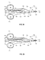
- Fig. 2A is side view of the forceps of Fig. 1 wherein a portion of one of the shaft members has been removed to shown the internal components thereof and wherein a knife assembly of the forceps is disposed in a retracted position;
- Fig. 2B is a side view of the forceps of Fig. 1 wherein a portion of one of the shaft members has been removed to shown the internal components thereof and wherein the knife assembly is disposed in an extended position;
- Fig. 3 is a enlarged, perspective view of an end effector assembly configured for use with the forceps of Fig. 1 ;
- Fig. 4 is a perspective view of the end effector assembly of Fig. 3 , shown with parts separated;
- Fig. 5A is a transverse, cross-sectional view of the jaw members of the end effector assembly of Fig. 3 shown in position for assembly;
- Fig. 5B is a transverse, cross-sectional view of the jaw members of the end effector assembly of Fig. 3 shown engaged to one another;
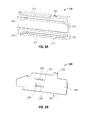
- Fig. 6A is a side, perspective view of a first component of a knife guide configured for use with the end effector assembly of Fig. 3 ;
- Fig. 6B is a side, perspective view of a second component of the knife guide
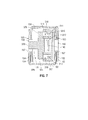
- Fig. 7 is a transverse, cross-sectional view of the end effector assembly of Fig. 3 in a fully assembled condition
- Fig. 8 is a side, perspective view of one of the jaw members of the end effector assembly of Fig. 3 ;
- Fig. 9 is a schematic illustration of two of the components used to form the jaw member of Fig. 8 .
- an open forceps 10 contemplated for use in connection with traditional open surgical procedures is shown.
- an open instrument e.g., forceps 10
- an endoscopic instrument (not shown) may be utilized in accordance with the present disclosure.
- different electrical and mechanical connections and considerations apply to each particular type of instrument; however, the novel aspects with respect to the end effector assembly and its operating characteristics remain generally consistent with respect to both the open and endoscopic configurations.
- forceps 10 includes two elongated shafts 12a and 12b, each having a proximal end 14a and 14b, and a distal end 16a and 16b, respectively.
- Forceps 10 further includes an end effector assembly 100 attached to distal ends 16a and 16b of shafts 12a and 12b, respectively.
- End effector assembly 100 includes a pair of opposing jaw members 110 and 120 that are pivotably connected about a pivot 103.
- Each shaft 12a and 12b includes a handle 17a and 17b disposed at the proximal end 14a and 14b thereof.
- Each handle 17a and 17b defines a finger hole 18a and 18b therethrough for receiving a finger of the user.
- finger holes 18a and 18b facilitate movement of the shaft members 12a and 12b relative to one another between a spaced-apart position and an approximated position, which, in turn, pivots jaw members 110 and 120 from an open position, wherein the jaw members 110 and 120 are disposed in spaced-apart relation relative to one another, to a closed position, wherein the jaw members 110 and 120 cooperate to grasp tissue therebetween.
- a ratchet 30 may be included for selectively locking the jaw members 110 and 120 relative to one another at various positions during pivoting.
- Ratchet 30 may include graduations or other visual markings that enable the user to easily and quickly ascertain and control the amount of closure force desired between the jaw members 110 and 120.
- one of the shafts e.g., shaft 12b, includes a proximal shaft connector 19 that is designed to connect the forceps 10 to a source of electrosurgical energy such as an electrosurgical generator (not shown).
- Proximal shaft connector 19 secures an electrosurgical cable 210 to forceps 10 such that the user may selectively apply electrosurgical energy to the electrically-conductive tissue sealing plates 112 and 122 (see Figs. 3-4 ) of jaw members 110 and 120, respectively.
- cable 210 includes a wire (or wires) (not shown) extending therethrough that has sufficient length to extend through one of the shaft members, e.g., shaft member 12b, in order to provide electrical energy to at least one of the sealing plates 112, 122 of jaw members 110, 120, respectively, of end effector assembly 100, e.g., upon activation of activation switch 40b.
- forceps 10 may be configured as a battery-powered instrument.
- Activation switch 40b is disposed at proximal end 14b of shaft member 12b and extends from shaft member 12b toward shaft member 12a.
- a corresponding surface 40a is defined along shaft member 12a toward proximal end 14a thereof and is configured to actuate activation switch 40b. More specifically, upon approximation of shaft members 12a, 12b, e.g., when jaw members 110, 120 are moved to the closed position, activation switch 40b is moved into contact with, or in close proximity of surface 40a. Upon further approximation of shaft members 12a, 12b, e.g., upon application of a pre-determined closure force to jaw members 110, 120, activation switch 40b is advanced further into surface 40a to depress activation switch 40b.
- Activation switch 40b controls the supply of electrosurgical energy to jaw members 110, 120 such that, upon depression of activation switch 40b, electrosurgical energy is supplied to sealing surface 112 and/or sealing surface 122 of jaw members 110, 120, respectively, to seal tissue grasped therebetween.
- Other more standardized activation switches are also contemplated, e.g., finger switch, toggle switch, foot switch, etc.
- forceps 10 may further include a knife assembly 140 disposed within one of the shaft members, e.g., shaft member 12a and a knife channel 115, 125 ( Fig. 4 ) defined within one or both of jaw members 110, 120, respectively, to permit reciprocation of knife 142 therethrough.
- Knife assembly 140 includes a rotatable trigger 144 coupled thereto that is rotatable about a pivot for advancing knife 142 from a retracted position within shaft member 12a ( Fig. 2A ), to an extended position ( Fig. 2B ), wherein knife 144 extends into knife channels 115, 125 to divide tissue grasped between jaw members 110, 120.
- axial rotation of trigger 144 effects longitudinal translation of knife 142.
- Other trigger assemblies are also contemplated.
- each jaw member 110, 120 of end effector assembly 100 includes a jaw frame 114, 124 having a proximal flange 150, 160 extending proximally therefrom.
- Jaw frames 114, 124 and proximal flanges 150, 160, respectively, thereof may be monolithically formed.
- jaw frames 114, 124 may be formed from a plurality of individual layers that are joined together, as will be described in greater detail below.
- Proximal flanges 150, 160 are engagable with one another to permit pivoting of jaw members 110, 120 relative to one another between the open position and the closed position upon movement of shaft members 12a, 12b ( Fig.
- Proximal flanges 150, 160 of jaw members 110, 120 also connect jaw members 110, 120 to the respective shaft members 12b, 12a thereof, e.g., via welding.
- Jaw members 110, 120 each further include an insulator 116, 126 disposed atop jaw frames 114, 124, respectively.
- Insulators 116, 126 are configured to receive electrically-conductive tissue sealing plates 112, 122, respectively, thereon and are configured to electrically isolate tissue sealing plates 112, 122 from the remaining components of the respective jaw member 110, 120.
- Outer jaw housings 118, 128 are disposed about tissue sealing plates 112, 122, jaw frames 114, 124, and insulators 116, 126, respectively, and are configured to house these components at least partially therein.
- outer jaw housings 118, 128 may be over-molded about jaw frames 114, 124, insulators 116, 126 and tissue sealing plates 112, 122, respectively, to engage the components of each respective jaw member 110, 120 to one another, although other manufacturing methods are also contemplated.
- tissue sealing plates 112, 122 of jaw members 110, 120 are disposed in opposed relation relative to one another such that, upon movement of jaw members 110, 120 to the closed position, tissue is grasped between tissue sealing plates 112, 122, respectively, thereof. Accordingly, in use, electrosurgical energy may be supplied to one or both of tissue sealing plates 112, 122 and conducted through tissue to seal tissue grasped therebetween and/or knife 142 ( Figs. 2A-2B ) may be advanced through knife channels 115, 125 of jaw members 110, 120 to cut tissue grasped therebetween.
- proximal flanges 150, 160 of jaw members 110, 120 each define a generally U-shaped, bifurcated configuration including first and second spaced-apart flange components 152, 154 and 162, 164, respectively.
- Flange components 152, 154 of proximal flange 150 of jaw member 110 cooperate to define a channel 156 extending longitudinally therebetween that is configured to receive one of the flange components, e.g., flange component 162, of proximal flange 160 of jaw member 120 therein.
- Flange components 162, 164 of proximal flange 160 of jaw member 120 similarly define a channel 166 extending longitudinally therebetween that is configured to receive one of the flange components, e.g., flange component 154, of proximal flange 150 of jaw member 110 therein.
- proximal flanges 150, 160 of jaw members 110, 120, respectively are configured for positioning relative to one another in an overlapping, offset configuration.
- other configurations e.g., wherein one of the proximal flanges 150, 160 is completely disposed within the other proximal flange 150, 160, are also contemplated.
- Each flange component 152, 154 and 162, 164 of jaw members 110, 120, respectively, includes an aperture 153, 155 and 163, 165, respectively, defined transversely therethrough. Apertures 153, 155 of flange components 152, 154, respectively, of jaw member 110 are aligned with one another and, similarly, apertures 163, 165 of flange components 162, 164, respectively, of jaw member 120 are aligned with one another.
- each aperture 153, 155, 163, 165 may define a similar diameter "D."
- Annular bosses 157, 167 each define a reduced outer diameter "d” as compared to diameter "D" of apertures 153, 155, 163, 165, i.e., annular bosses 157, 167 extend radially inwardly toward the longitudinal axes of apertures 155, 163, respectively, to cover at least a portion, e.g., the outer periphery, of apertures 155, 163.
- boss 167 of first flange component 162 of jaw member 120 may be pivotably engaged within aperture 153 of first flange component 152 of jaw member 110 and boss 157 of second flange component 154 of jaw member 110 may be pivotably engaged within aperture 165 of second flange component 164 of jaw member 120 in order to pivotable engage proximal flanges 150, 160 and, thus, jaw members 110, 120 to one another.
- jaw member 110 is inverted relative to jaw member 120 such that tissue sealing plates 112, 122 of jaw members 110, 120, respectively, oppose one another.
- proximal flanges 150, 160 are approximated relative to one another such that flange component 154 is disposed within channel 166 of proximal flange 160 of jaw member 120 and such that flange component 162 is disposed within channel 156 of proximal flange 150 of jaw member 110.
- proximal flanges 150, 160 are disposed in the overlapping, offset configuration wherein annular boss 167 of flange component 162 is positioned adjacent aperture 153 of flange component 152 and wherein annular boss 157 of flange component 154 is positioned adjacent aperture 165 of flange component 164.
- proximal flanges 150, 160 are urged toward one another such that annular boss 167 of flange component 162 is engaged within aperture 153 of flange component 152 and such that annular boss 157 of flange component 154 is engaged within aperture 165 of flange component 164, as shown in Fig. 5B .
- flange components 152, 162 are pivotably coupled to one another, i.e., annular boss 167 is rotatably engaged within aperture 153, and are substantially abutting or disposed in close proximity to one another and, similarly, flange components 154, 164 are pivotably coupled to one another, i.e., annular boss 157 is rotatably engaged within aperture 165, and are substantially abutting one another or in close proximity to one another.
- jaw members 110, 120 may be simultaneously pivoted (e.g., about these two boss-aperture couplings) relative to one another to move jaw members 110, 120 between the open and closed positions for grasping tissue therebetween.
- this pivotable coupling of bifurcated proximal flanges 150, 160 of jaw members 110, 120, respectively, is advantageous in that channels 156, 166 (collectively, lumen 170) defined within proximal flanges 150, 160, respectively, are substantially uninterrupted.
- knife 142 Figs. 2A-2B
- knife 142 need not be configured to pass over/under a pivot pin or define a slot therein for receiving the pivot pin therethrough since, instead of a pivot pin extending transversely through lumen 170 (formed by overlapping channels 156, 166 of proximal flanges 150, 160, respectively), proximal flanges 150, 160 are pivotably coupled to one another on either side of lumen 170.
- a guide member formed from first and second guide components 310, 320, respectively, is positionable within lumen 170 formed by proximal flanges 150, 160, respectively, of jaw members 110, 120 for providing support to and for locking proximal flanges 150, 160 in pivotable engagement with one another.
- Guide components 310, 320 may be formed via stamping, or any other suitable manufacturing process and/or each of guide components 310, 320 may be monolithically formed.
- first and second guide components 310, 320 of the guide member cooperate to guide translation of knife 142 therethrough and into knife channels 115, 125 defined within jaw members 110, 120, respectively, as knife 142 is translated between the retracted and extended positions (see Figs. 1-4 ).
- Guide components 310, 320 are further configured to route and protect the wire(s) (not shown) that extend from cable 210 and through shaft member 12b, ultimately coupling to tissue sealing plate 112 of jaw member 110 and/or tissue sealing plate 122 of jaw member 120 for providing electrosurgical energy thereto for sealing tissue grasped therebetween (see Figs. 1-4 ).
- first guide component 310 defines a generally rectangular configuration and is configured for insertion into lumen 170 defined by proximal flanges 150, 160 of jaw members 110, 120, respectively. More specifically, first guide component 310 is configured for longitudinal positioning adjacent one side of lumen 170, e.g., in abutting relation or close proximity relative to proximal flange components 152, 162 of jaw members 110, 120, respectively, such that first guide component 310 extends longitudinally between the components of each of proximal flanges 150, 160.
- First guide component 310 further includes a pair of longitudinal rails 311, 312 extending longitudinally therealong and protruding transversely therefrom into lumen 170, i.e., in a direction opposite of proximal flange components 152, 162 of jaw members 110, 120, respectively. Rails 311, 312 are spaced apart from one another to define a knife track 313 therebetween that is configured to guide reciprocation of knife 142 therethrough.
- a pair of opposed slots 314, 315 defined within first guide component 310 outside of, e.g., above and below, rails 311, 312 are configured to engage second guide component 320 ( Fig. 6B ) therein, as will be described in greater detail below.
- first and second bars 316, 317 extend longitudinally along and protrude from first guide component 310.
- Each bar 316, 317 is disposed adjacent to but spaced-apart from one of rails 311, 312, respectively, to define wire guides 318, 319, respectively, therebetween.
- a first wire guide 318 is defined between rail 311 and bar 316
- a second wire guide 319 is defined between rail 312 and bar 317.
- Wire guides 318, 319 are configured to route and protect the wires (not shown) that extend from electrosurgical cable 210 ( Fig. 1 ) through shaft 12b ( Fig. 1 ) and to tissue sealing plates 112, 122 of jaw members 110, 120, respectively, as mentioned above (see Fig. 4 ).
- second guide component 320 similarly defines a generally rectangular configuration and is configured for insertion into lumen 170 defined by proximal flanges 150, 160 of jaw members 110, 120, respectively. More specifically, second guide component 320 is configured for insertion into lumen 170 and for longitudinal positioning adjacent first guide component 310 such that opposed tabs 322, 324 of second guide component 320 are engaged, e.g., via snap-fit engagement, within opposed slots 314, 315 defined within first guide component 310. In this position, body 325 of second guide component 320 abuts longitudinal rails 311, 312 of first guide component 310 to fully enclose knife track 313 defined therebetween.
- first and second guide components 310, 320 cooperate to define a generally rectangular-shaped cross-sectional knife track 313 that is configured to guide reciprocation of the generally rectangular-shaped knife 142 between the retracted and extended positions and to inhibit splaying of knife 142 as knife 142 is advanced through tissue (see Figs. 2A-2B ).
- Other knife-track configurations formed complementarily to the knife to be translated therethrough are also contemplated.
- Body 325 of second guide component 320 also abuts bars 316, 317 when disposed within lumen 170 adjacent first guide component 310 such that wire guides 318, 319 are fully enclosed, thus providing additional protection for the wires (not shown) extending therethrough.
- Second guide component 320 further includes a cantilever arm 326 monolithically formed therewith.
- Cantilever arm 326 extends from fixed end 327 thereof adjacent a window 328 defined within second guide component 320 and includes a free end 329 that is biased outwardly to extend from window 328 and second guide component 320. More specifically, cantilever arm 326 extends from second guide component 320 towards proximal flange components 154, 164 of jaw members 110, 120, respectively.
- cantilever arm 326 flexed inwardly into window 328 to permit such insertion.
- free end 329 of cantilever arm 326 is eventually positioned adjacent apertures 155, 165 of flange components 154, 164, of jaw members 110, 120, respectively, thus allowing free end 329 of cantilever arm 326 to return under bias to the extended position, wherein cantilever arm 326 is disposed through apertures 155, 165, i.e., wherein cantilever arm 326 is resiliently biased.
- This engagement of cantilever arm 326 within apertures 155, 165 retains, or locks proximal flanges 150, 160, of jaw members 110, 120, respectively, in pivotable engagement with one another.
- first and second guide components 310, 320 may be configured such that, as shown in Fig. 7 , first and second guide components 310, 320, substantially occupy the volume of lumen 170, thus providing additional strength and support to jaw members 110, 120 and inhibiting disengagement of proximal flanges 150, 160, splaying of jaw members 110, 120, and/or lateral movement of jaw members 110, 120 relative to one another.
- jaw members 110, 120 of end effector assembly 100 are configured to engage respective shaft members 12b, 12a such that, as mentioned above, movement of shaft members 12a and 12b relative to one another between the spaced-apart position and the approximated position is imparted to jaw members 110, 120 for moving jaw members 110, 120 between the open position and the closed position for grasping tissue therebetween.
- Jaw members 110, 120 of end effector assembly 100 may be engaged to shaft members 12b, 12a, respectively, via welding, or any other suitable manufacturing process.
- Proximal flanges 150, 160 of jaw members 110, 120 may each include one or more features formed therein to facilitate welding of jaw members 110, 120 to shaft members 12b, 12a, respectively. More specifically, flange component 162 of proximal flange 160 of jaw member 120 may include a cut-out portion 182 configured to mate with a complementary-shaped portion of shaft member 12a to facilitate welding therebetween; flange component 164 of proximal flange 160 of jaw member 120 may include a post 184, spaced-apart from flange component 164 of proximal flange 160 (with slot 185 defined therebetween), that is configured to align with a portion of shaft member 12a to facilitate welding of jaw member 110 and shaft member 12a; and flange components 152, 154 of proximal flange 150 of jaw member 110 may each include a proximally-extending tab 186, 188 configured to provide an attachment area, e.g., a welding area, to facilitate welding jaw member 110 to shaft member
- jaw members 110, 120 of end effector assembly 100 may each be formed from a plurality of individual layers that are joined together. The manufacture of jaw member 120 will be described in greater detail below. Although only jaw member 120 is shown in Figs. 8-9 and described below, jaw member 110 may be formed similarly and, thus, will not be described herein for purposes of brevity.
- jaw member 120 includes a plurality of individual layers 220 joined together to form the completed jaw member 120.
- Each layer 220 may be formed from photochemical machining, stamping, or any other suitable manufacturing method. Photochemical machining in particular is advantageous in its ability to machine relatively hard, strong materials that could not be cut by conventional machining techniques.
- Using a plurality of individual layers 220 as opposed to a single component allows for the use of stronger materials for each layer 220, thus increasing the strength of jaw 120 without requiring an increase in size thereof. Further, this configuration allows any or all of the individual layers 220 to be made from different materials. As such, stronger materials can be used where required, e.g., for those layers 220 forming a portion of proximal flange component 162 or proximal flange component 164, while other materials may be use where added strength is not imperative.
- each individual layer 220 may be formed including a plurality of spaced-apart protrusions 222 extending from one side thereof and a plurality of similarly-spaced apertures 224 defined therein on the opposing side thereof. Accordingly, the protrusions 222 of each layer 220 may be engaged within the apertures 224 of the adjacent layer 220 to retain the layers 220 in fixed position, e.g., in the desired configuration, relative to one another. Thereafter, with the layers 220 fixed in the desired configuration, the layers 220 may be joined together, e.g., via integrated forming or welding, to form completed jaw member 120.
Landscapes
- Health & Medical Sciences (AREA)
- Surgery (AREA)
- Life Sciences & Earth Sciences (AREA)
- Engineering & Computer Science (AREA)
- Biomedical Technology (AREA)
- Public Health (AREA)
- Nuclear Medicine, Radiotherapy & Molecular Imaging (AREA)
- Veterinary Medicine (AREA)
- General Health & Medical Sciences (AREA)
- Heart & Thoracic Surgery (AREA)
- Medical Informatics (AREA)
- Molecular Biology (AREA)
- Animal Behavior & Ethology (AREA)
- Physics & Mathematics (AREA)
- Otolaryngology (AREA)
- Plasma & Fusion (AREA)
- Ophthalmology & Optometry (AREA)
- Surgical Instruments (AREA)
Abstract
Description
- The present disclosure relates to surgical instruments and, more particularly, to an open surgical forceps for grasping, sealing, and/or dividing tissue, and methods of manufacturing thereof.
- A forceps is a plier-like instrument which relies on mechanical action between its jaws to grasp, clamp and constrict vessels or tissue. Electrosurgical forceps utilize both mechanical clamping action and electrical energy to affect hemostasis by heating tissue and blood vessels to coagulate and/or cauterize tissue. Certain surgical procedures require more than simply cauterizing tissue and rely on the unique combination of clamping pressure, precise electrosurgical energy control and gap distance (i.e., distance between opposing jaw members when closed about tissue) to "seal" tissue, vessels and certain vascular bundles.
- Typically, once a vessel is sealed, the surgeon has to accurately sever the vessel along the newly formed tissue seal. Accordingly, many vessel sealing instruments have been designed which incorporate a knife or blade member which effectively severs the tissue after forming a tissue seal.
- As used herein, the term "distal" refers to the portion that is being described which is further from a user, while the term "proximal" refers to the portion that is being described which is closer to a user.
- In accordance with one aspect of the present disclosure, a forceps is provided. The forceps includes an end effector assembly having first and second jaw members. Each of the jaw members includes a proximal flange extending therefrom. The proximal flange of each jaw member defines a bifurcated configuration having first and second spaced-apart flange components. The first flange components of the jaw members are configured to pivotably engage one another via a first engagement portion and the second flange components of the jaw members are configured to pivotably engage one another via a second engagement portion independent of the first engagement. One or both of the jaw members is pivotable relative to the other about the first and second engagement portions between an open position and a closed position for grasping tissue therebetween.
- In an embodiment, a guide member is provided that is configured for positioning between the proximal flanges of the first and second jaw members. The guide member may include one (or more) tabs extending transversely therefrom that is configured to operably engage one of the first and second engagement portions or some other means to retain the jaw members in engagement with one another. The present disclosure encompasses forceps without including such a guide member.
- In one aspect, the first flange component of each of the jaw members includes an aperture defined transversely therethrough. One of the first flange components also includes a boss disposed about the aperture thereof. The boss is configured for engagement within the aperture of the other first flange component for pivotably engaging the first flange components to one another. The second flange components may be similarly configured.
- In an aspect, at least one of the engagement portions is provided by engaging a boss and an aperture.
- In another aspect, the tab is configured for engagement within an aperture defined through the first flange component(s) (or the second flange component(s)) of the jaw members.
- In an aspect, the tab may be configured to resiliently bias into engagement within one or more of the flange components.
- In another aspect, the proximal flanges of the jaw members are disposed in an overlapping, offset configuration relative to one another. That is, one of the flanges of the first jaw member is disposed inside the flanges of the second jaw member and the other of the flanges of the first jaw member is disposed outside of the flanges of the second jaw member.
- In still another aspect, the proximal flanges cooperate to define a lumen extending longitudinally therethrough. The guide member may be configured to substantially fill a volume of the lumen to inhibit lateral movement of the jaw members relative to one another. In an aspect, the forceps comprises a knife for cutting tissue that moves through the lumen to an extended, tissue cut position. In an aspect, wires are guided through the lumen for coupling to the first and/or the second jaw member to provide electrosurgical energy thereto.
- In an embodiment, the first flange components are spaced apart from the second flange components to define a lumen therebetween and a pivot structure about which the jaw members rotate between the open and closed position does not extend between the first flange components and the second flange components so as not to interrupt the lumen.
- In yet another aspect, the guide member is formed from first and second guide components, e.g., snap-fit in engagement with one another.
- In still yet another aspect, the guide member defines a knife track extending longitudinally therethrough. The knife track is configured to guide reciprocation of a knife therethrough for cutting tissue grasped between the jaw members.
- In another aspect, the guide member defines one or more wire guides extending longitudinally therethrough. The wire guide(s) is configured to route one or more wires therethrough for coupling to the first jaw member and/or the second jaw member to provide electrosurgical energy thereto.
- In yet another aspect, first and second shaft members are coupled to the first and second jaw members, respectively. The shaft members are movable relative to one another between a spaced-apart position and an approximated position to move the jaw members between the open position and the closed position.
- The first and second flange components of each of the jaw members may be welded to the respective shaft member thereof. Further, each jaw member may include a plurality of individual layer components joined together.
- In accordance with another aspect of the present disclosure, a forceps is provided including first and second shaft members, each shaft member having a jaw member disposed at a distal end thereof. Each of the jaw members includes a proximal flange extending therefrom that defines a bifurcated configuration having first and second spaced-apart flange components. The first flange components of the jaw members are pivotably engaged to one another via a first engagement portion and the second flange components of the jaw members are pivotably engaged one another via a second engagement portion such that movement of the shaft members relative to one another between a spaced-apart position and an approximated position effects movement of the jaw members between an open position and a closed position for grasping tissue therebetween. The proximal flanges of the first and second jaw members cooperate to define a lumen extending longitudinally therethrough between the first and second engagement portions thereof. Optionally, a guide member is disposed within the lumen and is engaged within one of the first and second engagement portions such that the proximal flanges are maintained in engagement with one another.
- In an aspect, the first engagement portion and the second engagement portion are spaced apart to define a lumen therebetween. Thus, the bearing parts of the pivotal engagement are spaced apart, i.e. do not extend into the lumen. The first and second engagement portions may be provided by spaced apart boss and aperture engagements. The bosses may protrude from respective flange components. The jaw members are rotatable about the first and second engagement portions between the open and closed positions.
- In one aspect, a knife assembly is disposed within one of the jaw members. The knife assembly includes a knife that is selectively translatable between a retracted position, wherein the knife is disposed within the jaw member, and an extended position, wherein the knife is advanced between the jaw members to cut tissue grasped therebetween. The knife may pass between the engagement portions in the lumen. In such an aspect, the guide member may include a knife track defined therein that is configured to guide translation of the knife between the retracted and extended positions.
- In another generally applicable aspect, the jaw members each include an electrically-conductive tissue sealing plate disposed thereon in opposed relation relative to one another. One or both of the tissue sealing plates is adapted to connect to a source of electrosurgical energy for sealing tissue grasped between the jaw members. One or more wires may extend in the lumen and be connected to provide electrosurgical energy to the tissue sealing plates. In such an aspect, the guide member may further be configured to define one or more wire guides extending longitudinally therethrough. The wire guide(s) is configured to route one or more wire therethrough for providing electrosurgical energy to the tissue sealing plates of the jaw members.
- In another aspect of the present disclosure, there is provided an end effector assembly comprising first and second jaw members openable and closeable relative to one another for grasping tissue, each jaw member comprising multiple individual layer components joined together.
- In an embodiment, the layer components each extend from a proximal portion to a distal portion of the jaw member.
- In an embodiment, the multiple individual layer components of the jaw members define opposing plates between which tissue can be grasped.
- In an embodiment, the layer components of each jaw member include outer layers providing flange components, wherein the flange components of one of the jaw members are pivotally connected to the flange components of the other of the jaw members. In an embodiment, inner ones of the individual layer components of each jaw member define a connecting plate between the outer layers, wherein the plates of the jaw members provide opposed areas between which tissue is to be grasped.
- In an embodiment, the layers are formed of metal.
- The layers may be formed with protrusions and recesses that cooperate with one another to assist joining.
- Various aspects of the present disclosure are described herein with reference to the drawings wherein like reference numerals identify similar or identical elements:
-
Fig. 1 is a side, perspective view of a forceps according to an apsect of the present disclosure; -
Fig. 2A is side view of the forceps ofFig. 1 wherein a portion of one of the shaft members has been removed to shown the internal components thereof and wherein a knife assembly of the forceps is disposed in a retracted position; -
Fig. 2B is a side view of the forceps ofFig. 1 wherein a portion of one of the shaft members has been removed to shown the internal components thereof and wherein the knife assembly is disposed in an extended position; -
Fig. 3 is a enlarged, perspective view of an end effector assembly configured for use with the forceps ofFig. 1 ; -
Fig. 4 is a perspective view of the end effector assembly ofFig. 3 , shown with parts separated; -
Fig. 5A is a transverse, cross-sectional view of the jaw members of the end effector assembly ofFig. 3 shown in position for assembly; -
Fig. 5B is a transverse, cross-sectional view of the jaw members of the end effector assembly ofFig. 3 shown engaged to one another; -
Fig. 6A is a side, perspective view of a first component of a knife guide configured for use with the end effector assembly ofFig. 3 ; -
Fig. 6B is a side, perspective view of a second component of the knife guide; -
Fig. 7 is a transverse, cross-sectional view of the end effector assembly ofFig. 3 in a fully assembled condition; -
Fig. 8 is a side, perspective view of one of the jaw members of the end effector assembly ofFig. 3 ; and -
Fig. 9 is a schematic illustration of two of the components used to form the jaw member ofFig. 8 . - Referring now to
Fig. 1 , anopen forceps 10 contemplated for use in connection with traditional open surgical procedures is shown. For the purposes herein, either an open instrument, e.g.,forceps 10, or an endoscopic instrument (not shown) may be utilized in accordance with the present disclosure. Obviously, different electrical and mechanical connections and considerations apply to each particular type of instrument; however, the novel aspects with respect to the end effector assembly and its operating characteristics remain generally consistent with respect to both the open and endoscopic configurations. - With continued reference to
Fig. 1 ,forceps 10 includes twoelongated shafts proximal end distal end Forceps 10 further includes anend effector assembly 100 attached todistal ends shafts End effector assembly 100 includes a pair of opposingjaw members pivot 103. Eachshaft handle proximal end handle finger hole finger holes shaft members jaw members jaw members jaw members - A
ratchet 30 may be included for selectively locking thejaw members Ratchet 30 may include graduations or other visual markings that enable the user to easily and quickly ascertain and control the amount of closure force desired between thejaw members - Continuing with reference to
Fig. 1 , one of the shafts, e.g.,shaft 12b, includes aproximal shaft connector 19 that is designed to connect theforceps 10 to a source of electrosurgical energy such as an electrosurgical generator (not shown).Proximal shaft connector 19 secures anelectrosurgical cable 210 to forceps 10 such that the user may selectively apply electrosurgical energy to the electrically-conductivetissue sealing plates 112 and 122 (seeFigs. 3-4 ) ofjaw members cable 210 includes a wire (or wires) (not shown) extending therethrough that has sufficient length to extend through one of the shaft members, e.g.,shaft member 12b, in order to provide electrical energy to at least one of the sealingplates jaw members end effector assembly 100, e.g., upon activation ofactivation switch 40b. Alternatively,forceps 10 may be configured as a battery-powered instrument. -
Activation switch 40b is disposed atproximal end 14b ofshaft member 12b and extends fromshaft member 12b towardshaft member 12a. Acorresponding surface 40a is defined alongshaft member 12a towardproximal end 14a thereof and is configured to actuateactivation switch 40b. More specifically, upon approximation ofshaft members jaw members activation switch 40b is moved into contact with, or in close proximity ofsurface 40a. Upon further approximation ofshaft members jaw members activation switch 40b is advanced further intosurface 40a to depressactivation switch 40b.Activation switch 40b controls the supply of electrosurgical energy tojaw members activation switch 40b, electrosurgical energy is supplied to sealingsurface 112 and/or sealingsurface 122 ofjaw members - Referring now to
Figs. 2A-2B , in conjunction withFig. 1 ,forceps 10 may further include aknife assembly 140 disposed within one of the shaft members, e.g.,shaft member 12a and aknife channel 115, 125 (Fig. 4 ) defined within one or both ofjaw members knife 142 therethrough.Knife assembly 140 includes arotatable trigger 144 coupled thereto that is rotatable about a pivot for advancingknife 142 from a retracted position withinshaft member 12a (Fig. 2A ), to an extended position (Fig. 2B ), whereinknife 144 extends intoknife channels jaw members trigger 144 effects longitudinal translation ofknife 142. Other trigger assemblies are also contemplated. - Turning now to
Figs. 3-4 , eachjaw member end effector assembly 100 includes ajaw frame proximal flange proximal flanges Proximal flanges jaw members shaft members Fig. 1 ) relative to one another between the spaced-apart and approximated positions.Proximal flanges jaw members jaw members respective shaft members -
Jaw members insulator Insulators tissue sealing plates tissue sealing plates respective jaw member Outer jaw housings tissue sealing plates insulators outer jaw housings insulators tissue sealing plates respective jaw member - In the fully assembled condition, as shown in
Fig. 3 ,tissue sealing plates jaw members jaw members tissue sealing plates tissue sealing plates Figs. 2A-2B ) may be advanced throughknife channels jaw members - With continued reference to
Figs. 3-4 , in conjunction withFigs. 5A-5B ,proximal flanges jaw members flange components Flange components proximal flange 150 ofjaw member 110 cooperate to define achannel 156 extending longitudinally therebetween that is configured to receive one of the flange components, e.g.,flange component 162, ofproximal flange 160 ofjaw member 120 therein.Flange components proximal flange 160 ofjaw member 120 similarly define achannel 166 extending longitudinally therebetween that is configured to receive one of the flange components, e.g.,flange component 154, ofproximal flange 150 ofjaw member 110 therein. In other words,proximal flanges jaw members proximal flanges proximal flange - Each
flange component jaw members aperture Apertures flange components jaw member 110 are aligned with one another and, similarly,apertures flange components jaw member 120 are aligned with one another. Further, eachaperture proximal flange 150, e.g.,flange component 154, and one of the flange components ofproximal flange 160, e.g.,flange component 162, each include anannular boss respective aperture surface 159, 169, respectively, thereof.Annular bosses apertures annular bosses apertures apertures proximal flanges boss 167 offirst flange component 162 ofjaw member 120 may be pivotably engaged withinaperture 153 offirst flange component 152 ofjaw member 110 andboss 157 ofsecond flange component 154 ofjaw member 110 may be pivotably engaged withinaperture 165 ofsecond flange component 164 ofjaw member 120 in order to pivotable engageproximal flanges jaw members - Continuing with reference to
Figs. 3-4 and5A-5B , the pivotable coupling ofjaw members jaw member 110 is inverted relative tojaw member 120 such thattissue sealing plates jaw members proximal flanges jaw members proximal flange channel proximal flange jaw members - With
jaw member 110 inverted relative tojaw member 120,proximal flanges flange component 154 is disposed withinchannel 166 ofproximal flange 160 ofjaw member 120 and such thatflange component 162 is disposed withinchannel 156 ofproximal flange 150 ofjaw member 110. In other words, in this position, as best shown inFig. 5A ,proximal flanges annular boss 167 offlange component 162 is positionedadjacent aperture 153 offlange component 152 and whereinannular boss 157 offlange component 154 is positionedadjacent aperture 165 offlange component 164. - In order to pivotably engage
proximal flange 150 ofjaw member 110 andproximal flange 160 ofjaw member 120 to one another, withproximal flanges Fig. 5A ,proximal flanges annular boss 167 offlange component 162 is engaged withinaperture 153 offlange component 152 and such thatannular boss 157 offlange component 154 is engaged withinaperture 165 offlange component 164, as shown inFig. 5B . In this position,flange components annular boss 167 is rotatably engaged withinaperture 153, and are substantially abutting or disposed in close proximity to one another and, similarly,flange components annular boss 157 is rotatably engaged withinaperture 165, and are substantially abutting one another or in close proximity to one another. As such,jaw members jaw members proximal flanges jaw members channels 156, 166 (collectively, lumen 170) defined withinproximal flanges Figs. 2A-2B ) need not be configured to pass over/under a pivot pin or define a slot therein for receiving the pivot pin therethrough since, instead of a pivot pin extending transversely through lumen 170 (formed by overlappingchannels proximal flanges proximal flanges lumen 170. - Turning now to
Figs. 6A-6B and7 , a guide member formed from first andsecond guide components lumen 170 formed byproximal flanges jaw members proximal flanges Guide components guide components second guide components knife 142 therethrough and intoknife channels jaw members knife 142 is translated between the retracted and extended positions (seeFigs. 1-4 ).Guide components cable 210 and throughshaft member 12b, ultimately coupling totissue sealing plate 112 ofjaw member 110 and/ortissue sealing plate 122 ofjaw member 120 for providing electrosurgical energy thereto for sealing tissue grasped therebetween (seeFigs. 1-4 ). - Referring to
Figs. 6A and7 ,first guide component 310 defines a generally rectangular configuration and is configured for insertion intolumen 170 defined byproximal flanges jaw members first guide component 310 is configured for longitudinal positioning adjacent one side oflumen 170, e.g., in abutting relation or close proximity relative toproximal flange components jaw members first guide component 310 extends longitudinally between the components of each ofproximal flanges First guide component 310 further includes a pair oflongitudinal rails lumen 170, i.e., in a direction opposite ofproximal flange components jaw members Rails knife track 313 therebetween that is configured to guide reciprocation ofknife 142 therethrough. A pair ofopposed slots first guide component 310 outside of, e.g., above and below, rails 311, 312 are configured to engage second guide component 320 (Fig. 6B ) therein, as will be described in greater detail below. Further, first andsecond bars first guide component 310. Eachbar rails first wire guide 318 is defined betweenrail 311 andbar 316, and asecond wire guide 319 is defined betweenrail 312 andbar 317. Wire guides 318, 319 are configured to route and protect the wires (not shown) that extend from electrosurgical cable 210 (Fig. 1 ) throughshaft 12b (Fig. 1 ) and totissue sealing plates jaw members Fig. 4 ). - With reference now to
Figs. 6B and7 ,second guide component 320 similarly defines a generally rectangular configuration and is configured for insertion intolumen 170 defined byproximal flanges jaw members second guide component 320 is configured for insertion intolumen 170 and for longitudinal positioning adjacentfirst guide component 310 such that opposedtabs second guide component 320 are engaged, e.g., via snap-fit engagement, withinopposed slots first guide component 310. In this position,body 325 ofsecond guide component 320 abutslongitudinal rails first guide component 310 to fully encloseknife track 313 defined therebetween. As such, first andsecond guide components cross-sectional knife track 313 that is configured to guide reciprocation of the generally rectangular-shapedknife 142 between the retracted and extended positions and to inhibit splaying ofknife 142 asknife 142 is advanced through tissue (seeFigs. 2A-2B ). Other knife-track configurations formed complementarily to the knife to be translated therethrough are also contemplated.Body 325 ofsecond guide component 320 also abutsbars lumen 170 adjacentfirst guide component 310 such that wire guides 318, 319 are fully enclosed, thus providing additional protection for the wires (not shown) extending therethrough. -
Second guide component 320 further includes acantilever arm 326 monolithically formed therewith.Cantilever arm 326 extends from fixedend 327 thereof adjacent awindow 328 defined withinsecond guide component 320 and includes afree end 329 that is biased outwardly to extend fromwindow 328 andsecond guide component 320. More specifically,cantilever arm 326 extends fromsecond guide component 320 towardsproximal flange components jaw members second guide component 320 intolumen 170 defined byproximal flanges jaw members cantilever arm 326 is flexed inwardly intowindow 328 to permit such insertion. Assecond guide component 320 is inserted further throughlumen 170,free end 329 ofcantilever arm 326 is eventually positionedadjacent apertures flange components jaw members free end 329 ofcantilever arm 326 to return under bias to the extended position, whereincantilever arm 326 is disposed throughapertures cantilever arm 326 is resiliently biased. This engagement ofcantilever arm 326 withinapertures proximal flanges jaw members second guide components Fig. 7 , first andsecond guide components lumen 170, thus providing additional strength and support tojaw members proximal flanges jaw members jaw members - Turning now to
Figs. 1 and3-4 ,jaw members end effector assembly 100 are configured to engagerespective shaft members shaft members jaw members jaw members Jaw members end effector assembly 100 may be engaged toshaft members -
Proximal flanges jaw members jaw members shaft members flange component 162 ofproximal flange 160 ofjaw member 120 may include a cut-outportion 182 configured to mate with a complementary-shaped portion ofshaft member 12a to facilitate welding therebetween;flange component 164 ofproximal flange 160 ofjaw member 120 may include apost 184, spaced-apart fromflange component 164 of proximal flange 160 (withslot 185 defined therebetween), that is configured to align with a portion ofshaft member 12a to facilitate welding ofjaw member 110 andshaft member 12a; andflange components proximal flange 150 ofjaw member 110 may each include a proximally-extendingtab welding jaw member 110 toshaft member 12b. This configuration, wherein eachflange component jaw members respective shaft member forceps 10. - Referring now to
Figs. 8-9 , as mentioned above,jaw members Fig. 4 ) may each be formed from a plurality of individual layers that are joined together. The manufacture ofjaw member 120 will be described in greater detail below. Althoughonly jaw member 120 is shown inFigs. 8-9 and described below,jaw member 110 may be formed similarly and, thus, will not be described herein for purposes of brevity. - Continuing with reference to
Figs. 8-9 ,jaw member 120 includes a plurality ofindividual layers 220 joined together to form the completedjaw member 120. Eachlayer 220 may be formed from photochemical machining, stamping, or any other suitable manufacturing method. Photochemical machining in particular is advantageous in its ability to machine relatively hard, strong materials that could not be cut by conventional machining techniques. Using a plurality ofindividual layers 220 as opposed to a single component allows for the use of stronger materials for eachlayer 220, thus increasing the strength ofjaw 120 without requiring an increase in size thereof. Further, this configuration allows any or all of theindividual layers 220 to be made from different materials. As such, stronger materials can be used where required, e.g., for thoselayers 220 forming a portion ofproximal flange component 162 orproximal flange component 164, while other materials may be use where added strength is not imperative. - As best shown in
Fig. 9 , eachindividual layer 220 may be formed including a plurality of spaced-apartprotrusions 222 extending from one side thereof and a plurality of similarly-spacedapertures 224 defined therein on the opposing side thereof. Accordingly, theprotrusions 222 of eachlayer 220 may be engaged within theapertures 224 of theadjacent layer 220 to retain thelayers 220 in fixed position, e.g., in the desired configuration, relative to one another. Thereafter, with thelayers 220 fixed in the desired configuration, thelayers 220 may be joined together, e.g., via integrated forming or welding, to form completedjaw member 120. - From the foregoing and with reference to the various figure drawings, those skilled in the art will appreciate that certain modifications can also be made to the present disclosure without departing from the scope of the same. While several embodiments of the disclosure have been shown in the drawings, it is not intended that the disclosure be limited thereto, as it is intended that the disclosure be as broad in scope as the art will allow and that the specification be read likewise. Therefore, the above description should not be construed as limiting, but merely as exemplifications of particular embodiments. Those skilled in the art will envision other modifications within the scope and spirit of the claims appended hereto.
Claims (14)
- A forceps, comprising:an end effector assembly including first and second jaw members, each of the jaw members including a proximal flange extending therefrom, each proximal flange defining a bifurcated configuration having first and second spaced-apart flange components, the first flange components of the jaw members configured to pivotably engage one another via a first engagement portion and the second flange components of the jaw members configured to pivotably engage one another via a second engagement portion independent of the first engagement portion, at least one of the first and second jaw members pivotable relative to the other about the first and second engagement portions between an open position and a closed position for grasping tissue therebetween; anda guide member configured for positioning between the proximal flanges of the first and second jaw members, the guide member including at least one tab extending transversely therefrom, the tab configured to operably engage one of the first and second engagement portions to retain the jaw members in engagement with one another.
- The forceps according to claim 1, wherein the first flange component of each of the jaw members includes an aperture defined transversely therethrough, one of the first flange components including a boss disposed about the aperture thereof, the boss configured for engagement within the aperture of the other first flange component for pivotably engaging the first flange components to one another.
- The forceps according to claim 2, wherein the tab is configured for engagement within the aperture defined within each of the first flange components.
- The forceps according to claim 3, wherein the tab is configured to resiliently bias into engagement within the apertures defined within the first flange components.
- The forceps according to claim 1, 2, 3 or 4, wherein the second flange component of each of the jaw members includes an aperture defined transversely therethrough, one of the second flange components including a boss disposed about the aperture thereof, the boss configured for engagement within the aperture of the other second flange component for pivotably engaging the second flange components to one another.
- The forceps according to any preceding claim, wherein the proximal flanges are disposed in an overlapping, offset configuration relative to one another.
- The forceps according to any preceding claim, wherein the proximal flanges cooperate to define a lumen extending longitudinally therethrough.
- The forceps according any preceding to claim, wherein the guide member is configured to substantially fill a volume of the lumen to inhibit lateral movement of the jaw members relative to one another.
- The forceps according to any preceding claim, wherein the guide member is formed from first and second guide components.
- The forceps according to any preceding claim, wherein the guide member defines a knife track extending longitudinally therethrough, the knife track configured to guide reciprocation of a knife therethrough for cutting tissue grasped between the jaw members.
- The forceps according to any preceding claim, wherein the guide member defines at least one wire guide extending longitudinally therethrough, the at least one wire guide configured to route at least one wire therethrough for coupling to at least one of the jaw members.
- The forceps according to any preceding claim, further comprising first and second shaft members, the first shaft member coupled to the first jaw member and the second shaft member coupled to the second jaw member such that movement of the shaft members relative to one another between a spaced-apart position and an approximated position effects movement of the jaw members between the open position and the closed position.
- The forceps according to claim 12, wherein the first and second flange components of each of the jaw members are welded to the respective shaft member thereof.
- The forceps according to any preceding claim, wherein each of the jaw members includes a plurality of individual layer components joined together.
Priority Applications (1)
| Application Number | Priority Date | Filing Date | Title |
|---|---|---|---|
| EP15167291.2A EP2926748B1 (en) | 2012-05-01 | 2013-05-02 | Surgical forceps |
Applications Claiming Priority (1)
| Application Number | Priority Date | Filing Date | Title |
|---|---|---|---|
| US13/461,397 US8920461B2 (en) | 2012-05-01 | 2012-05-01 | Surgical forceps with bifurcated flanged jaw components |
Related Child Applications (2)
| Application Number | Title | Priority Date | Filing Date |
|---|---|---|---|
| EP15167291.2A Division-Into EP2926748B1 (en) | 2012-05-01 | 2013-05-02 | Surgical forceps |
| EP15167291.2A Division EP2926748B1 (en) | 2012-05-01 | 2013-05-02 | Surgical forceps |
Publications (3)
| Publication Number | Publication Date |
|---|---|
| EP2659843A2 true EP2659843A2 (en) | 2013-11-06 |
| EP2659843A3 EP2659843A3 (en) | 2014-05-28 |
| EP2659843B1 EP2659843B1 (en) | 2015-07-29 |
Family
ID=48190845
Family Applications (2)
| Application Number | Title | Priority Date | Filing Date |
|---|---|---|---|
| EP13166210.8A Active EP2659843B1 (en) | 2012-05-01 | 2013-05-02 | Surgical forceps |
| EP15167291.2A Active EP2926748B1 (en) | 2012-05-01 | 2013-05-02 | Surgical forceps |
Family Applications After (1)
| Application Number | Title | Priority Date | Filing Date |
|---|---|---|---|
| EP15167291.2A Active EP2926748B1 (en) | 2012-05-01 | 2013-05-02 | Surgical forceps |
Country Status (3)
| Country | Link |
|---|---|
| US (2) | US8920461B2 (en) |
| EP (2) | EP2659843B1 (en) |
| CN (1) | CN103381107B (en) |
Families Citing this family (61)
| Publication number | Priority date | Publication date | Assignee | Title |
|---|---|---|---|---|
| US7364577B2 (en) | 2002-02-11 | 2008-04-29 | Sherwood Services Ag | Vessel sealing system |
| DE60121229T2 (en) | 2001-04-06 | 2007-05-24 | Sherwood Services Ag | DEVICE FOR SEALING AND SHARING A VESSEL WITH NON-LASTING END STOP |
| US7628791B2 (en) | 2005-08-19 | 2009-12-08 | Covidien Ag | Single action tissue sealer |
| US8298232B2 (en) | 2006-01-24 | 2012-10-30 | Tyco Healthcare Group Lp | Endoscopic vessel sealer and divider for large tissue structures |
| US8357158B2 (en) | 2008-04-22 | 2013-01-22 | Covidien Lp | Jaw closure detection system |
| US8469956B2 (en) | 2008-07-21 | 2013-06-25 | Covidien Lp | Variable resistor jaw |
| US8133254B2 (en) | 2009-09-18 | 2012-03-13 | Tyco Healthcare Group Lp | In vivo attachable and detachable end effector assembly and laparoscopic surgical instrument and methods therefor |
| US8512371B2 (en) | 2009-10-06 | 2013-08-20 | Covidien Lp | Jaw, blade and gap manufacturing for surgical instruments with small jaws |
| US8480671B2 (en) | 2010-01-22 | 2013-07-09 | Covidien Lp | Compact jaw including split pivot pin |
| US8439913B2 (en) | 2010-04-29 | 2013-05-14 | Covidien Lp | Pressure sensing sealing plate |
| US8469991B2 (en) | 2010-06-02 | 2013-06-25 | Covidien Lp | Apparatus for performing an electrosurgical procedure |
| US8491624B2 (en) | 2010-06-02 | 2013-07-23 | Covidien Lp | Apparatus for performing an electrosurgical procedure |
| US8430877B2 (en) | 2010-06-02 | 2013-04-30 | Covidien Lp | Apparatus for performing an electrosurgical procedure |
| US8968309B2 (en) | 2011-11-10 | 2015-03-03 | Covidien Lp | Surgical forceps |
| US8747434B2 (en) | 2012-02-20 | 2014-06-10 | Covidien Lp | Knife deployment mechanisms for surgical forceps |
| US8887373B2 (en) | 2012-02-24 | 2014-11-18 | Covidien Lp | Vessel sealing instrument with reduced thermal spread and method of manufacture therefor |
| US8968311B2 (en) | 2012-05-01 | 2015-03-03 | Covidien Lp | Surgical instrument with stamped double-flag jaws and actuation mechanism |
| US9668807B2 (en) | 2012-05-01 | 2017-06-06 | Covidien Lp | Simplified spring load mechanism for delivering shaft force of a surgical instrument |
| US9820765B2 (en) | 2012-05-01 | 2017-11-21 | Covidien Lp | Surgical instrument with stamped double-flange jaws |
| US8920461B2 (en) | 2012-05-01 | 2014-12-30 | Covidien Lp | Surgical forceps with bifurcated flanged jaw components |
| US9039691B2 (en) | 2012-06-29 | 2015-05-26 | Covidien Lp | Surgical forceps |
| US8939975B2 (en) | 2012-07-17 | 2015-01-27 | Covidien Lp | Gap control via overmold teeth and hard stops |
| US9192421B2 (en) | 2012-07-24 | 2015-11-24 | Covidien Lp | Blade lockout mechanism for surgical forceps |
| US9636168B2 (en) | 2012-08-09 | 2017-05-02 | Covidien Lp | Electrosurgical instrument including nested knife assembly |
| US9526564B2 (en) | 2012-10-08 | 2016-12-27 | Covidien Lp | Electric stapler device |
| US9265566B2 (en) | 2012-10-16 | 2016-02-23 | Covidien Lp | Surgical instrument |
| US9375259B2 (en) | 2012-10-24 | 2016-06-28 | Covidien Lp | Electrosurgical instrument including an adhesive applicator assembly |
| USD728786S1 (en) | 2013-05-03 | 2015-05-05 | Covidien Lp | Vessel sealer with mechanical cutter and pistol-grip-style trigger |
| US9642671B2 (en) | 2013-09-30 | 2017-05-09 | Covidien Lp | Limited-use medical device |
| USD788302S1 (en) | 2013-10-01 | 2017-05-30 | Covidien Lp | Knife for endoscopic electrosurgical forceps |
| US10080605B2 (en) | 2014-09-17 | 2018-09-25 | Covidien Lp | Deployment mechanisms for surgical instruments |
| US10039592B2 (en) | 2014-09-17 | 2018-08-07 | Covidien Lp | Deployment mechanisms for surgical instruments |
| US10080606B2 (en) | 2014-09-17 | 2018-09-25 | Covidien Lp | Method of forming a member of an end effector |
| US9987076B2 (en) | 2014-09-17 | 2018-06-05 | Covidien Lp | Multi-function surgical instruments |
| US9987077B2 (en) | 2014-09-17 | 2018-06-05 | Covidien Lp | Surgical instrument having a bipolar end effector assembly and a deployable monopolar assembly |
| US9918785B2 (en) | 2014-09-17 | 2018-03-20 | Covidien Lp | Deployment mechanisms for surgical instruments |
| US11207127B2 (en) | 2014-09-25 | 2021-12-28 | Covidien Lp | Surgical instruments facilitating replacement of disposable components and/or sterilization of reusable components |
| US10172612B2 (en) | 2015-01-21 | 2019-01-08 | Covidien Lp | Surgical instruments with force applier and methods of use |
| USD844138S1 (en) | 2015-07-17 | 2019-03-26 | Covidien Lp | Handle assembly of a multi-function surgical instrument |
| USD844139S1 (en) | 2015-07-17 | 2019-03-26 | Covidien Lp | Monopolar assembly of a multi-function surgical instrument |
| US9987078B2 (en) | 2015-07-22 | 2018-06-05 | Covidien Lp | Surgical forceps |
| US10537381B2 (en) | 2016-02-26 | 2020-01-21 | Covidien Lp | Surgical instrument having a bipolar end effector assembly and a deployable monopolar assembly |
| US10492852B2 (en) * | 2017-02-27 | 2019-12-03 | Covidien Lp | Wire guide for surgical instruments and surgical instruments including a wire guide |
| US11154348B2 (en) | 2017-08-29 | 2021-10-26 | Covidien Lp | Surgical instruments and methods of assembling surgical instruments |
| US11241275B2 (en) | 2018-03-21 | 2022-02-08 | Covidien Lp | Energy-based surgical instrument having multiple operational configurations |
| US11123132B2 (en) | 2018-04-09 | 2021-09-21 | Covidien Lp | Multi-function surgical instruments and assemblies therefor |
| US10828756B2 (en) | 2018-04-24 | 2020-11-10 | Covidien Lp | Disassembly methods facilitating reprocessing of multi-function surgical instruments |
| US11896291B2 (en) | 2018-07-02 | 2024-02-13 | Covidien Lp | Electrically-insulative shafts, methods of manufacturing electrically-insulative shafts, and energy-based surgical instruments incorporating electrically-insulative shafts |
| US11490953B2 (en) | 2018-10-01 | 2022-11-08 | Covidien Lp | Electrosurgical instrument and passively cooled jaw members thereof |
| US11419665B2 (en) | 2018-10-26 | 2022-08-23 | Covidien Lp | Electrosurgical forceps |
| US11350982B2 (en) * | 2018-12-05 | 2022-06-07 | Covidien Lp | Electrosurgical forceps |
| US11510725B2 (en) | 2019-01-30 | 2022-11-29 | Covidien Lp | Electrosurgical forceps |
| US11304743B2 (en) | 2019-01-30 | 2022-04-19 | Covidien Lp | Electrosurgical forceps |
| US11497545B2 (en) | 2019-02-14 | 2022-11-15 | Covidien Lp | Electrosurgical forceps |
| US11712287B2 (en) * | 2019-04-18 | 2023-08-01 | Biosense Webster (Israel) Ltd. | Grasper tool with coagulation |
| EP3744266B1 (en) | 2019-05-27 | 2024-02-28 | Erbe Elektromedizin GmbH | Electro-surgical instrument |
| US12185964B2 (en) | 2020-09-10 | 2025-01-07 | Covidien Lp | End effector assemblies for surgical instruments such as for use in robotic surgical systems |
| US12161386B2 (en) | 2020-09-11 | 2024-12-10 | Covidien Lp | Surgical instruments having an articulating section such as for use in robotic surgical systems |
| US11925406B2 (en) | 2020-09-14 | 2024-03-12 | Covidien Lp | End effector assemblies for surgical instruments |
| US12290256B1 (en) | 2022-06-02 | 2025-05-06 | Lonnie J. Ginn | Suture cutter device and method of use |
| DE102024127261A1 (en) * | 2024-09-20 | 2026-03-26 | Aesculap Ag | Electrosurgical bipolar forceps with a metal part and a metal sheet stacking arrangement |
Family Cites Families (146)
| Publication number | Priority date | Publication date | Assignee | Title |
|---|---|---|---|---|
| US2801633A (en) | 1954-02-17 | 1957-08-06 | Joseph C Ehrlich | Lancets |
| SU401367A1 (en) | 1971-10-05 | 1973-10-12 | Тернопольский государственный медицинский институт | BIAKTIVNYE ELECTRO SURGICAL INSTRUMENT |
| DE2415263A1 (en) | 1974-03-29 | 1975-10-02 | Aesculap Werke Ag | Surgical H.F. coagulation probe has electrode tongs - with exposed ends of insulated conductors forming tong-jaws |
| DE2514501A1 (en) | 1975-04-03 | 1976-10-21 | Karl Storz | Bipolar coagulation instrument for endoscopes - has two high frequency electrodes looped over central insulating piece |
| FR2315286A2 (en) | 1975-06-26 | 1977-01-21 | Lamidey Marcel | H.F. blood coagulating dissecting forceps - with adjustable stops to vary clamping space and circuit making contacts |
| DE3490633T (en) | 1984-01-30 | 1985-12-12 | Char'kovskaja oblastnaja kliničeskaja bol'nica, Char'kov | Bipolar electrosurgical device |
| JPS60211451A (en) | 1984-04-05 | 1985-10-23 | Asahi Chem Ind Co Ltd | Photosensitive elastomer composition |
| DE3423356C2 (en) | 1984-06-25 | 1986-06-26 | Berchtold Medizin-Elektronik GmbH & Co, 7200 Tuttlingen | Electrosurgical high frequency cutting instrument |
| US4657016A (en) | 1984-08-20 | 1987-04-14 | Garito Jon C | Electrosurgical handpiece for blades, needles and forceps |
| JPH0540112Y2 (en) | 1987-03-03 | 1993-10-12 | ||
| DE8712328U1 (en) | 1987-09-11 | 1988-02-18 | Jakoubek, Franz, 7201 Emmingen-Liptingen | Endoscopy forceps |
| US5100420A (en) * | 1989-07-18 | 1992-03-31 | United States Surgical Corporation | Apparatus and method for applying surgical clips in laparoscopic or endoscopic procedures |
| JP2806511B2 (en) | 1990-07-31 | 1998-09-30 | 松下電工株式会社 | Manufacturing method of sintered alloy |
| US5389102A (en) | 1990-09-13 | 1995-02-14 | United States Surgical Corporation | Apparatus and method for subcuticular stapling of body tissue |
| US5190541A (en) | 1990-10-17 | 1993-03-02 | Boston Scientific Corporation | Surgical instrument and method |
| JP2951418B2 (en) | 1991-02-08 | 1999-09-20 | トキコ株式会社 | Sample liquid component analyzer |
| US5324289A (en) | 1991-06-07 | 1994-06-28 | Hemostatic Surgery Corporation | Hemostatic bi-polar electrosurgical cutting apparatus and methods of use |
| US5242456A (en) | 1991-11-21 | 1993-09-07 | Kensey Nash Corporation | Apparatus and methods for clamping tissue and reflecting the same |
| US5383471A (en) | 1992-04-10 | 1995-01-24 | Funnell; David M. | Surgical biopsy instrument |
| JPH0630945A (en) | 1992-05-19 | 1994-02-08 | Olympus Optical Co Ltd | Suturing apparatus |
| CA2104423A1 (en) | 1992-08-24 | 1994-02-25 | Boris Zvenyatsky | Handle for endoscopic instruments and jaw structure |
| DE4303882C2 (en) | 1993-02-10 | 1995-02-09 | Kernforschungsz Karlsruhe | Combination instrument for separation and coagulation for minimally invasive surgery |
| JP3390041B2 (en) | 1993-04-05 | 2003-03-24 | オリンパス光学工業株式会社 | Forceps |
| GB9309142D0 (en) | 1993-05-04 | 1993-06-16 | Gyrus Medical Ltd | Laparoscopic instrument |
| US5693051A (en) | 1993-07-22 | 1997-12-02 | Ethicon Endo-Surgery, Inc. | Electrosurgical hemostatic device with adaptive electrodes |
| GB9322464D0 (en) | 1993-11-01 | 1993-12-22 | Gyrus Medical Ltd | Electrosurgical apparatus |
| DE4403252A1 (en) | 1994-02-03 | 1995-08-10 | Michael Hauser | Instrument shaft for min. invasive surgery |
| GB9413070D0 (en) | 1994-06-29 | 1994-08-17 | Gyrus Medical Ltd | Electrosurgical apparatus |
| US5456684A (en) | 1994-09-08 | 1995-10-10 | Hutchinson Technology Incorporated | Multifunctional minimally invasive surgical instrument |
| GB9425781D0 (en) | 1994-12-21 | 1995-02-22 | Gyrus Medical Ltd | Electrosurgical instrument |
| DE19506363A1 (en) | 1995-02-24 | 1996-08-29 | Frost Lore Geb Haupt | Non-invasive thermometry in organs under hyperthermia and coagulation conditions |
| JPH08289895A (en) | 1995-04-21 | 1996-11-05 | Olympus Optical Co Ltd | Suture device |
| DE19515914C1 (en) | 1995-05-02 | 1996-07-25 | Aesculap Ag | Tong or scissor-shaped surgical instrument |
| US6293942B1 (en) | 1995-06-23 | 2001-09-25 | Gyrus Medical Limited | Electrosurgical generator method |
| JPH1024051A (en) | 1995-09-20 | 1998-01-27 | Olympus Optical Co Ltd | Coagulation forceps with separating function |
| USH1745H (en) | 1995-09-29 | 1998-08-04 | Paraschac; Joseph F. | Electrosurgical clamping device with insulation limited bipolar electrode |
| US5707392A (en) | 1995-09-29 | 1998-01-13 | Symbiosis Corporation | Hermaphroditic stamped forceps jaw for disposable endoscopic biopsy forceps and method of making the same |
| AU703455B2 (en) | 1995-10-20 | 1999-03-25 | Ethicon Endo-Surgery, Inc. | Self protecting knife for curved jaw surgical instruments |
| US5673842A (en) | 1996-03-05 | 1997-10-07 | Ethicon Endo-Surgery | Surgical stapler with locking mechanism |
| DE19608716C1 (en) | 1996-03-06 | 1997-04-17 | Aesculap Ag | Bipolar surgical holding instrument |
| DE29616210U1 (en) | 1996-09-18 | 1996-11-14 | Olympus Winter & Ibe Gmbh, 22045 Hamburg | Handle for surgical instruments |
| US5923475A (en) | 1996-11-27 | 1999-07-13 | Eastman Kodak Company | Laser printer using a fly's eye integrator |
| JP3836551B2 (en) | 1996-12-04 | 2006-10-25 | ペンタックス株式会社 | Endoscopic hot biopsy forceps |
| US5891142A (en) | 1996-12-06 | 1999-04-06 | Eggers & Associates, Inc. | Electrosurgical forceps |
| USH1904H (en) | 1997-05-14 | 2000-10-03 | Ethicon Endo-Surgery, Inc. | Electrosurgical hemostatic method and device |
| USH2037H1 (en) | 1997-05-14 | 2002-07-02 | David C. Yates | Electrosurgical hemostatic device including an anvil |
| JP3986127B2 (en) | 1997-08-06 | 2007-10-03 | オリンパス株式会社 | Endoscopic surgical instrument |
| DE19738457B4 (en) | 1997-09-03 | 2009-01-02 | Celon Ag Medical Instruments | Method and device for in vivo deep coagulation of biological tissue volumes while sparing the tissue surface with high frequency alternating current |
| US5980510A (en) | 1997-10-10 | 1999-11-09 | Ethicon Endo-Surgery, Inc. | Ultrasonic clamp coagulator apparatus having improved clamp arm pivot mount |
| DE19751108A1 (en) | 1997-11-18 | 1999-05-20 | Beger Frank Michael Dipl Desig | Electrosurgical operation tool, especially for diathermy |
| JPH11169381A (en) | 1997-12-15 | 1999-06-29 | Olympus Optical Co Ltd | High frequency treating device |
| EP0923907A1 (en) | 1997-12-19 | 1999-06-23 | Gyrus Medical Limited | An electrosurgical instrument |
| US7267677B2 (en) | 1998-10-23 | 2007-09-11 | Sherwood Services Ag | Vessel sealing instrument |
| CA2347014C (en) | 1998-10-23 | 2011-01-04 | Sherwood Services Ag | Open vessel sealing forceps with disposable electrodes |
| DE19858512C1 (en) | 1998-12-18 | 2000-05-25 | Storz Karl Gmbh & Co Kg | Bipolar medical instrument for minimally invasive surgery for endoscopic operations; has mutually insulated leads passing through tubular shaft to conductor elements on linked jaw parts |
| DE19915061A1 (en) | 1999-04-01 | 2000-10-26 | Erbe Elektromedizin | Surgical instrument |
| GB9911956D0 (en) | 1999-05-21 | 1999-07-21 | Gyrus Medical Ltd | Electrosurgery system and method |
| GB9911954D0 (en) | 1999-05-21 | 1999-07-21 | Gyrus Medical Ltd | Electrosurgery system and instrument |
| GB9912627D0 (en) | 1999-05-28 | 1999-07-28 | Gyrus Medical Ltd | An electrosurgical instrument |
| GB9912625D0 (en) | 1999-05-28 | 1999-07-28 | Gyrus Medical Ltd | An electrosurgical generator and system |
| GB9913652D0 (en) | 1999-06-11 | 1999-08-11 | Gyrus Medical Ltd | An electrosurgical generator |
| JP2001003400A (en) | 1999-06-21 | 2001-01-09 | Sumitomo Constr Mach Co Ltd | Monitor device for hydraulic shovel |
| US6117158A (en) | 1999-07-07 | 2000-09-12 | Ethicon Endo-Surgery, Inc. | Ratchet release mechanism for hand held instruments |
| DE19940689A1 (en) | 1999-08-27 | 2001-04-05 | Storz Karl Gmbh & Co Kg | Bipolar medical instrument |
| US6423051B1 (en) | 1999-09-16 | 2002-07-23 | Aaron V. Kaplan | Methods and apparatus for pericardial access |
| DE19946527C1 (en) | 1999-09-28 | 2001-07-12 | Storz Karl Gmbh & Co Kg | Bipolar, e.g. laparoscopic surgery instrument, cuts electrically, cauterizes and grips using simple design with high frequency current-concentrating projections |
| US20030109875A1 (en) | 1999-10-22 | 2003-06-12 | Tetzlaff Philip M. | Open vessel sealing forceps with disposable electrodes |
| JP4315557B2 (en) | 2000-01-12 | 2009-08-19 | オリンパス株式会社 | Medical treatment tool |
| DE10003020C2 (en) | 2000-01-25 | 2001-12-06 | Aesculap Ag & Co Kg | Bipolar barrel instrument |
| DE10031773B4 (en) | 2000-05-04 | 2007-11-29 | Erbe Elektromedizin Gmbh | Surgical gripping instrument, in particular tweezers or forceps |
| DE10027727C1 (en) | 2000-06-03 | 2001-12-06 | Aesculap Ag & Co Kg | Scissors-shaped or forceps-shaped surgical instrument |
| DE10045375C2 (en) | 2000-09-14 | 2002-10-24 | Aesculap Ag & Co Kg | Medical instrument |
| EP1331887A4 (en) | 2000-10-20 | 2006-07-12 | Dvl Acquisition Sub Inc | Surgical suturing instrument and method of use |
| JP3523839B2 (en) | 2000-10-30 | 2004-04-26 | オリンパス株式会社 | Surgical instruments |
| DE10061278B4 (en) | 2000-12-08 | 2004-09-16 | GFD-Gesellschaft für Diamantprodukte mbH | Instrument for surgical purposes |
| US20020111624A1 (en) | 2001-01-26 | 2002-08-15 | Witt David A. | Coagulating electrosurgical instrument with tissue dam |
| DE20121161U1 (en) | 2001-01-31 | 2002-04-04 | Olympus Winter & Ibe Gmbh, 22045 Hamburg | Endoscopic instrument |
| JP4125133B2 (en) | 2001-04-06 | 2008-07-30 | シャーウッド・サービシーズ・アクチェンゲゼルシャフト | Molded insulating hinges for bipolar devices |
| US6733514B2 (en) * | 2001-10-05 | 2004-05-11 | Pilling Weck Incorporated | Jaw assembly for endoscopic instruments |
| US6878147B2 (en) | 2001-11-02 | 2005-04-12 | Vivant Medical, Inc. | High-strength microwave antenna assemblies |
| US6676660B2 (en) | 2002-01-23 | 2004-01-13 | Ethicon Endo-Surgery, Inc. | Feedback light apparatus and method for use with an electrosurgical instrument |
| EP2289429B1 (en) * | 2002-05-10 | 2015-06-17 | Covidien LP | Surgical stapling apparatus having a wound closure material applicator assembly |
| JP4459814B2 (en) | 2002-10-04 | 2010-04-28 | コヴィディエン アクチェンゲゼルシャフト | Electrode assembly for sealing and cutting tissue and method for performing sealing and cutting tissue |
| JP2003175052A (en) | 2002-11-01 | 2003-06-24 | Olympus Optical Co Ltd | Coagulation treatment tool |
| US7244257B2 (en) | 2002-11-05 | 2007-07-17 | Sherwood Services Ag | Electrosurgical pencil having a single button variable control |
| US7150749B2 (en) | 2003-06-13 | 2006-12-19 | Sherwood Services Ag | Vessel sealer and divider having elongated knife stroke and safety cutting mechanism |
| USD545432S1 (en) | 2003-08-08 | 2007-06-26 | Olympus Corporation | Distal portion of hemostatic forceps for endoscope |
| US7131970B2 (en) | 2003-11-19 | 2006-11-07 | Sherwood Services Ag | Open vessel sealing instrument with cutting mechanism |
| US7252667B2 (en) | 2003-11-19 | 2007-08-07 | Sherwood Services Ag | Open vessel sealing instrument with cutting mechanism and distal lockout |
| JP4624697B2 (en) | 2004-03-12 | 2011-02-02 | オリンパス株式会社 | Surgical instrument |
| USD541938S1 (en) | 2004-04-09 | 2007-05-01 | Sherwood Services Ag | Open vessel sealer with mechanical cutter |
| DE102004026179B4 (en) | 2004-05-14 | 2009-01-22 | Erbe Elektromedizin Gmbh | Electrosurgical instrument |
| USD533942S1 (en) | 2004-06-30 | 2006-12-19 | Sherwood Services Ag | Open vessel sealer with mechanical cutter |
| JP2006015078A (en) | 2004-07-05 | 2006-01-19 | Olympus Corp | Medical apparatus |
| DE102004040959B4 (en) | 2004-08-24 | 2008-12-24 | Erbe Elektromedizin Gmbh | Surgical instrument |
| USD541418S1 (en) | 2004-10-06 | 2007-04-24 | Sherwood Services Ag | Lung sealing device |
| USD535027S1 (en) | 2004-10-06 | 2007-01-09 | Sherwood Services Ag | Low profile vessel sealing and cutting mechanism |
| USD567943S1 (en) | 2004-10-08 | 2008-04-29 | Sherwood Services Ag | Over-ratchet safety for a vessel sealing instrument |
| USD533274S1 (en) | 2004-10-12 | 2006-12-05 | Allegiance Corporation | Handle for surgical suction-irrigation device |
| USD582038S1 (en) | 2004-10-13 | 2008-12-02 | Medtronic, Inc. | Transurethral needle ablation device |
| USD564662S1 (en) | 2004-10-13 | 2008-03-18 | Sherwood Services Ag | Hourglass-shaped knife for electrosurgical forceps |
| USD538932S1 (en) | 2005-06-30 | 2007-03-20 | Medical Action Industries Inc. | Surgical needle holder |
| US7722607B2 (en) | 2005-09-30 | 2010-05-25 | Covidien Ag | In-line vessel sealer and divider |
| DE102006042985A1 (en) | 2005-10-04 | 2007-04-19 | Erbe Elektromedizin Gmbh | Electrosurgical instrument for coagulating tissue, has deformable unit arranged on branch or gripping device such that area of gripping device can be moved to actuate switching device when branches are closed and minimum distance is reached |
| US8298232B2 (en) | 2006-01-24 | 2012-10-30 | Tyco Healthcare Group Lp | Endoscopic vessel sealer and divider for large tissue structures |
| US7766910B2 (en) | 2006-01-24 | 2010-08-03 | Tyco Healthcare Group Lp | Vessel sealer and divider for large tissue structures |
| US8734443B2 (en) | 2006-01-24 | 2014-05-27 | Covidien Lp | Vessel sealer and divider for large tissue structures |
| USD541611S1 (en) | 2006-01-26 | 2007-05-01 | Robert Bosch Gmbh | Cordless screwdriver |
| US7641653B2 (en) | 2006-05-04 | 2010-01-05 | Covidien Ag | Open vessel sealing forceps disposable handswitch |
| EP2040634B1 (en) * | 2006-07-13 | 2014-06-11 | Bovie Medical Corporation | Surgical sealing and cutting apparatus |
| USD547154S1 (en) | 2006-09-08 | 2007-07-24 | Winsource Industries Limited | Rotary driving tool |
| DE102006059175A1 (en) | 2006-12-14 | 2008-06-26 | Erbe Elektromedizin Gmbh | Tubular shaft device e.g. electrosurgical tubular shaft device, for e.g. coagulating tissue of patient, has pivot for rotatably supporting jaw parts and formed in such manner that rotational axis of pivot lies outside jaw parts |
| DE102006047204B4 (en) * | 2006-10-05 | 2015-04-23 | Erbe Elektromedizin Gmbh | Tubular shaft instrument |
| USD649249S1 (en) | 2007-02-15 | 2011-11-22 | Tyco Healthcare Group Lp | End effectors of an elongated dissecting and dividing instrument |
| USD575395S1 (en) | 2007-02-15 | 2008-08-19 | Tyco Healthcare Group Lp | Hemostat style elongated dissecting and dividing instrument |
| USD575401S1 (en) | 2007-06-12 | 2008-08-19 | Tyco Healthcare Group Lp | Vessel sealer |
| DE202007009318U1 (en) | 2007-06-26 | 2007-08-30 | Aesculap Ag & Co. Kg | Surgical instrument |
| DE202007009317U1 (en) | 2007-06-26 | 2007-08-30 | Aesculap Ag & Co. Kg | Surgical instrument |
| DE202007009165U1 (en) | 2007-06-29 | 2007-08-30 | Kls Martin Gmbh + Co. Kg | Surgical instrument |
| US20090088750A1 (en) | 2007-09-28 | 2009-04-02 | Tyco Healthcare Group Lp | Insulating Boot with Silicone Overmold for Electrosurgical Forceps |
| US20090088743A1 (en) | 2007-09-28 | 2009-04-02 | Shinya Masuda | Surgical operating apparatus |
| DE202007016233U1 (en) | 2007-11-20 | 2008-01-31 | Aesculap Ag & Co. Kg | Surgical forceps |
| JP5496520B2 (en) | 2008-02-14 | 2014-05-21 | エシコン・エンド−サージェリィ・インコーポレイテッド | Motorized cutting and fastening device with control circuit to optimize battery use |
| US8328802B2 (en) | 2008-03-19 | 2012-12-11 | Covidien Ag | Cordless medical cauterization and cutting device |
| DE102008018406B3 (en) | 2008-04-10 | 2009-07-23 | Bowa-Electronic Gmbh & Co. Kg | Electrosurgical device |
| EP2344048B1 (en) | 2008-07-30 | 2016-09-07 | Neotract, Inc. | Slotted anchor device |
| USD621503S1 (en) | 2009-04-28 | 2010-08-10 | Tyco Healthcare Group Ip | Pistol grip laparoscopic sealing and dissection device |
| USD617900S1 (en) | 2009-05-13 | 2010-06-15 | Tyco Healthcare Group Lp | End effector tip with undercut bottom jaw |
| USD618798S1 (en) | 2009-05-13 | 2010-06-29 | Tyco Healthcare Group Lp | Vessel sealing jaw seal plate |
| USD649643S1 (en) | 2009-05-13 | 2011-11-29 | Tyco Healthcare Group Lp | End effector with a rounded tip |
| USD617901S1 (en) | 2009-05-13 | 2010-06-15 | Tyco Healthcare Group Lp | End effector chamfered tip |
| USD617903S1 (en) | 2009-05-13 | 2010-06-15 | Tyco Healthcare Group Lp | End effector pointed tip |
| USD617902S1 (en) | 2009-05-13 | 2010-06-15 | Tyco Healthcare Group Lp | End effector tip with undercut top jaw |
| US8246618B2 (en) | 2009-07-08 | 2012-08-21 | Tyco Healthcare Group Lp | Electrosurgical jaws with offset knife |
| USD630324S1 (en) | 2009-08-05 | 2011-01-04 | Tyco Healthcare Group Lp | Dissecting surgical jaw |
| USD627462S1 (en) | 2009-09-09 | 2010-11-16 | Tyco Healthcare Group Lp | Knife channel of a jaw device |
| US8133254B2 (en) | 2009-09-18 | 2012-03-13 | Tyco Healthcare Group Lp | In vivo attachable and detachable end effector assembly and laparoscopic surgical instrument and methods therefor |
| USD628290S1 (en) | 2009-11-30 | 2010-11-30 | Tyco Healthcare Group Lp | Surgical instrument handle |
| USD628289S1 (en) | 2009-11-30 | 2010-11-30 | Tyco Healthcare Group Lp | Surgical instrument handle |
| JP5579427B2 (en) | 2009-12-14 | 2014-08-27 | 中国電力株式会社 | Indirect hot wire work tool support device |
| US8480671B2 (en) | 2010-01-22 | 2013-07-09 | Covidien Lp | Compact jaw including split pivot pin |
| US8597295B2 (en) | 2010-04-12 | 2013-12-03 | Covidien Lp | Surgical instrument with non-contact electrical coupling |
| US9028495B2 (en) | 2010-06-23 | 2015-05-12 | Covidien Lp | Surgical instrument with a separable coaxial joint |
| US9655672B2 (en) | 2010-10-04 | 2017-05-23 | Covidien Lp | Vessel sealing instrument |
| USD661394S1 (en) | 2011-02-24 | 2012-06-05 | Tyco Healthcare Group Lp | Device jaw |
| US8920461B2 (en) | 2012-05-01 | 2014-12-30 | Covidien Lp | Surgical forceps with bifurcated flanged jaw components |
-
2012
- 2012-05-01 US US13/461,397 patent/US8920461B2/en active Active
-
2013
- 2013-04-28 CN CN201310156950.9A patent/CN103381107B/en active Active
- 2013-05-02 EP EP13166210.8A patent/EP2659843B1/en active Active
- 2013-05-02 EP EP15167291.2A patent/EP2926748B1/en active Active
-
2014
- 2014-12-22 US US14/579,446 patent/US9345536B2/en active Active
Non-Patent Citations (1)
| Title |
|---|
| None |
Also Published As
| Publication number | Publication date |
|---|---|
| CN103381107A (en) | 2013-11-06 |
| EP2659843B1 (en) | 2015-07-29 |
| US20150112338A1 (en) | 2015-04-23 |
| EP2659843A3 (en) | 2014-05-28 |
| EP2926748B1 (en) | 2019-12-25 |
| US20130296856A1 (en) | 2013-11-07 |
| EP2926748A1 (en) | 2015-10-07 |
| US8920461B2 (en) | 2014-12-30 |
| US9345536B2 (en) | 2016-05-24 |
| CN103381107B (en) | 2017-03-01 |
Similar Documents
| Publication | Publication Date | Title |
|---|---|---|
| EP2926748B1 (en) | Surgical forceps | |
| EP2659844B1 (en) | Surgical forceps | |
| US9192421B2 (en) | Blade lockout mechanism for surgical forceps | |
| US20220142701A1 (en) | Latching mechanism for in-line activated electrosurgical device | |
| CN103381108B (en) | Medical devices having jaws and actuation mechanisms with stamped double flags | |
| US5800449A (en) | Knife shield for surgical instruments | |
| US8968317B2 (en) | Surgical forceps | |
| US9770253B2 (en) | Surgical forceps | |
| EP2735274B1 (en) | Surgical apparatus | |
| US8685056B2 (en) | Surgical forceps | |
| US7951150B2 (en) | Vessel sealer and divider with rotating sealer and cutter | |
| US20130046303A1 (en) | Surgical Forceps | |
| US20110238067A1 (en) | Open vessel sealing instrument with cutting mechanism | |
| US20200305964A1 (en) | Blade escape prevention feature for surgical instrument and method for preventing same | |
| US11350982B2 (en) | Electrosurgical forceps | |
| AU2015203543B2 (en) | Surgical forceps | |
| CA2532713A1 (en) | Vessel sealer and divider with rotating sealer and cutter |
Legal Events
| Date | Code | Title | Description |
|---|---|---|---|
| PUAI | Public reference made under article 153(3) epc to a published international application that has entered the european phase |
Free format text: ORIGINAL CODE: 0009012 |
|
| AK | Designated contracting states |
Kind code of ref document: A2 Designated state(s): AL AT BE BG CH CY CZ DE DK EE ES FI FR GB GR HR HU IE IS IT LI LT LU LV MC MK MT NL NO PL PT RO RS SE SI SK SM TR |
|
| AX | Request for extension of the european patent |
Extension state: BA ME |
|
| REG | Reference to a national code |
Ref country code: DE Ref legal event code: R079 Ref document number: 602013002415 Country of ref document: DE Free format text: PREVIOUS MAIN CLASS: A61B0017285000 Ipc: A61B0017290000 |
|
| PUAL | Search report despatched |
Free format text: ORIGINAL CODE: 0009013 |
|
| AK | Designated contracting states |
Kind code of ref document: A3 Designated state(s): AL AT BE BG CH CY CZ DE DK EE ES FI FR GB GR HR HU IE IS IT LI LT LU LV MC MK MT NL NO PL PT RO RS SE SI SK SM TR |
|
| AX | Request for extension of the european patent |
Extension state: BA ME |
|
| RIC1 | Information provided on ipc code assigned before grant |
Ipc: A61B 18/14 20060101ALI20140423BHEP Ipc: A61B 17/29 20060101AFI20140423BHEP Ipc: A61B 17/28 20060101ALI20140423BHEP Ipc: A61B 17/285 20060101ALI20140423BHEP Ipc: A61B 17/295 20060101ALI20140423BHEP |
|
| 17P | Request for examination filed |
Effective date: 20141125 |
|
| RBV | Designated contracting states (corrected) |
Designated state(s): AL AT BE BG CH CY CZ DE DK EE ES FI FR GB GR HR HU IE IS IT LI LT LU LV MC MK MT NL NO PL PT RO RS SE SI SK SM TR |
|
| GRAP | Despatch of communication of intention to grant a patent |
Free format text: ORIGINAL CODE: EPIDOSNIGR1 |
|
| RIN1 | Information on inventor provided before grant (corrected) |
Inventor name: ALLEN IV, JAMES D. Inventor name: UNGER, JEFFRREY R. Inventor name: JOSEPH, DANIEL A. |
|
| INTG | Intention to grant announced |
Effective date: 20150209 |
|
| GRAS | Grant fee paid |
Free format text: ORIGINAL CODE: EPIDOSNIGR3 |
|
| GRAA | (expected) grant |
Free format text: ORIGINAL CODE: 0009210 |
|
| RIN1 | Information on inventor provided before grant (corrected) |
Inventor name: ALLEN IV, JAMES D. Inventor name: UNGER, JEFFREY R. Inventor name: JOSEPH, DANIEL A. |
|
| AK | Designated contracting states |
Kind code of ref document: B1 Designated state(s): AL AT BE BG CH CY CZ DE DK EE ES FI FR GB GR HR HU IE IS IT LI LT LU LV MC MK MT NL NO PL PT RO RS SE SI SK SM TR |
|
| REG | Reference to a national code |
Ref country code: GB Ref legal event code: FG4D |
|
| REG | Reference to a national code |
Ref country code: CH Ref legal event code: EP |
|
| REG | Reference to a national code |
Ref country code: AT Ref legal event code: REF Ref document number: 738644 Country of ref document: AT Kind code of ref document: T Effective date: 20150815 |
|
| REG | Reference to a national code |
Ref country code: IE Ref legal event code: FG4D |
|
| REG | Reference to a national code |
Ref country code: DE Ref legal event code: R096 Ref document number: 602013002415 Country of ref document: DE |
|
| REG | Reference to a national code |
Ref country code: AT Ref legal event code: MK05 Ref document number: 738644 Country of ref document: AT Kind code of ref document: T Effective date: 20150729 |
|
| REG | Reference to a national code |
Ref country code: LT Ref legal event code: MG4D |
|
| REG | Reference to a national code |
Ref country code: NL Ref legal event code: MP Effective date: 20150729 |
|
| PG25 | Lapsed in a contracting state [announced via postgrant information from national office to epo] |
Ref country code: FI Free format text: LAPSE BECAUSE OF FAILURE TO SUBMIT A TRANSLATION OF THE DESCRIPTION OR TO PAY THE FEE WITHIN THE PRESCRIBED TIME-LIMIT Effective date: 20150729 Ref country code: LT Free format text: LAPSE BECAUSE OF FAILURE TO SUBMIT A TRANSLATION OF THE DESCRIPTION OR TO PAY THE FEE WITHIN THE PRESCRIBED TIME-LIMIT Effective date: 20150729 Ref country code: NO Free format text: LAPSE BECAUSE OF FAILURE TO SUBMIT A TRANSLATION OF THE DESCRIPTION OR TO PAY THE FEE WITHIN THE PRESCRIBED TIME-LIMIT Effective date: 20151029 Ref country code: LV Free format text: LAPSE BECAUSE OF FAILURE TO SUBMIT A TRANSLATION OF THE DESCRIPTION OR TO PAY THE FEE WITHIN THE PRESCRIBED TIME-LIMIT Effective date: 20150729 Ref country code: GR Free format text: LAPSE BECAUSE OF FAILURE TO SUBMIT A TRANSLATION OF THE DESCRIPTION OR TO PAY THE FEE WITHIN THE PRESCRIBED TIME-LIMIT Effective date: 20151030 |
|
| PG25 | Lapsed in a contracting state [announced via postgrant information from national office to epo] |
Ref country code: RS Free format text: LAPSE BECAUSE OF FAILURE TO SUBMIT A TRANSLATION OF THE DESCRIPTION OR TO PAY THE FEE WITHIN THE PRESCRIBED TIME-LIMIT Effective date: 20150729 Ref country code: ES Free format text: LAPSE BECAUSE OF FAILURE TO SUBMIT A TRANSLATION OF THE DESCRIPTION OR TO PAY THE FEE WITHIN THE PRESCRIBED TIME-LIMIT Effective date: 20150729 Ref country code: SE Free format text: LAPSE BECAUSE OF FAILURE TO SUBMIT A TRANSLATION OF THE DESCRIPTION OR TO PAY THE FEE WITHIN THE PRESCRIBED TIME-LIMIT Effective date: 20150729 Ref country code: HR Free format text: LAPSE BECAUSE OF FAILURE TO SUBMIT A TRANSLATION OF THE DESCRIPTION OR TO PAY THE FEE WITHIN THE PRESCRIBED TIME-LIMIT Effective date: 20150729 Ref country code: PT Free format text: LAPSE BECAUSE OF FAILURE TO SUBMIT A TRANSLATION OF THE DESCRIPTION OR TO PAY THE FEE WITHIN THE PRESCRIBED TIME-LIMIT Effective date: 20151130 Ref country code: AT Free format text: LAPSE BECAUSE OF FAILURE TO SUBMIT A TRANSLATION OF THE DESCRIPTION OR TO PAY THE FEE WITHIN THE PRESCRIBED TIME-LIMIT Effective date: 20150729 Ref country code: IS Free format text: LAPSE BECAUSE OF FAILURE TO SUBMIT A TRANSLATION OF THE DESCRIPTION OR TO PAY THE FEE WITHIN THE PRESCRIBED TIME-LIMIT Effective date: 20151129 Ref country code: PL Free format text: LAPSE BECAUSE OF FAILURE TO SUBMIT A TRANSLATION OF THE DESCRIPTION OR TO PAY THE FEE WITHIN THE PRESCRIBED TIME-LIMIT Effective date: 20150729 |
|
| PG25 | Lapsed in a contracting state [announced via postgrant information from national office to epo] |
Ref country code: NL Free format text: LAPSE BECAUSE OF FAILURE TO SUBMIT A TRANSLATION OF THE DESCRIPTION OR TO PAY THE FEE WITHIN THE PRESCRIBED TIME-LIMIT Effective date: 20150729 |
|
| REG | Reference to a national code |
Ref country code: FR Ref legal event code: PLFP Year of fee payment: 4 |
|
| PG25 | Lapsed in a contracting state [announced via postgrant information from national office to epo] |
Ref country code: IT Free format text: LAPSE BECAUSE OF FAILURE TO SUBMIT A TRANSLATION OF THE DESCRIPTION OR TO PAY THE FEE WITHIN THE PRESCRIBED TIME-LIMIT Effective date: 20150729 Ref country code: DK Free format text: LAPSE BECAUSE OF FAILURE TO SUBMIT A TRANSLATION OF THE DESCRIPTION OR TO PAY THE FEE WITHIN THE PRESCRIBED TIME-LIMIT Effective date: 20150729 Ref country code: EE Free format text: LAPSE BECAUSE OF FAILURE TO SUBMIT A TRANSLATION OF THE DESCRIPTION OR TO PAY THE FEE WITHIN THE PRESCRIBED TIME-LIMIT Effective date: 20150729 Ref country code: CZ Free format text: LAPSE BECAUSE OF FAILURE TO SUBMIT A TRANSLATION OF THE DESCRIPTION OR TO PAY THE FEE WITHIN THE PRESCRIBED TIME-LIMIT Effective date: 20150729 Ref country code: SK Free format text: LAPSE BECAUSE OF FAILURE TO SUBMIT A TRANSLATION OF THE DESCRIPTION OR TO PAY THE FEE WITHIN THE PRESCRIBED TIME-LIMIT Effective date: 20150729 |
|
| REG | Reference to a national code |
Ref country code: DE Ref legal event code: R097 Ref document number: 602013002415 Country of ref document: DE |
|
| PG25 | Lapsed in a contracting state [announced via postgrant information from national office to epo] |
Ref country code: RO Free format text: LAPSE BECAUSE OF FAILURE TO SUBMIT A TRANSLATION OF THE DESCRIPTION OR TO PAY THE FEE WITHIN THE PRESCRIBED TIME-LIMIT Effective date: 20150729 |
|
| PLBE | No opposition filed within time limit |
Free format text: ORIGINAL CODE: 0009261 |
|
| STAA | Information on the status of an ep patent application or granted ep patent |
Free format text: STATUS: NO OPPOSITION FILED WITHIN TIME LIMIT |
|
| 26N | No opposition filed |
Effective date: 20160502 |
|
| PG25 | Lapsed in a contracting state [announced via postgrant information from national office to epo] |
Ref country code: SI Free format text: LAPSE BECAUSE OF FAILURE TO SUBMIT A TRANSLATION OF THE DESCRIPTION OR TO PAY THE FEE WITHIN THE PRESCRIBED TIME-LIMIT Effective date: 20150729 Ref country code: BE Free format text: LAPSE BECAUSE OF NON-PAYMENT OF DUE FEES Effective date: 20160531 |
|
| PG25 | Lapsed in a contracting state [announced via postgrant information from national office to epo] |
Ref country code: LU Free format text: LAPSE BECAUSE OF FAILURE TO SUBMIT A TRANSLATION OF THE DESCRIPTION OR TO PAY THE FEE WITHIN THE PRESCRIBED TIME-LIMIT Effective date: 20160502 Ref country code: BE Free format text: LAPSE BECAUSE OF FAILURE TO SUBMIT A TRANSLATION OF THE DESCRIPTION OR TO PAY THE FEE WITHIN THE PRESCRIBED TIME-LIMIT Effective date: 20150729 |
|
| REG | Reference to a national code |
Ref country code: CH Ref legal event code: PL |
|
| PG25 | Lapsed in a contracting state [announced via postgrant information from national office to epo] |
Ref country code: LI Free format text: LAPSE BECAUSE OF NON-PAYMENT OF DUE FEES Effective date: 20160531 Ref country code: CH Free format text: LAPSE BECAUSE OF NON-PAYMENT OF DUE FEES Effective date: 20160531 |
|
| REG | Reference to a national code |
Ref country code: FR Ref legal event code: PLFP Year of fee payment: 5 |
|
| REG | Reference to a national code |
Ref country code: FR Ref legal event code: PLFP Year of fee payment: 6 |
|
| PG25 | Lapsed in a contracting state [announced via postgrant information from national office to epo] |
Ref country code: CY Free format text: LAPSE BECAUSE OF FAILURE TO SUBMIT A TRANSLATION OF THE DESCRIPTION OR TO PAY THE FEE WITHIN THE PRESCRIBED TIME-LIMIT Effective date: 20150729 Ref country code: SM Free format text: LAPSE BECAUSE OF FAILURE TO SUBMIT A TRANSLATION OF THE DESCRIPTION OR TO PAY THE FEE WITHIN THE PRESCRIBED TIME-LIMIT Effective date: 20150729 Ref country code: HU Free format text: LAPSE BECAUSE OF FAILURE TO SUBMIT A TRANSLATION OF THE DESCRIPTION OR TO PAY THE FEE WITHIN THE PRESCRIBED TIME-LIMIT; INVALID AB INITIO Effective date: 20130502 |
|
| PG25 | Lapsed in a contracting state [announced via postgrant information from national office to epo] |
Ref country code: MK Free format text: LAPSE BECAUSE OF FAILURE TO SUBMIT A TRANSLATION OF THE DESCRIPTION OR TO PAY THE FEE WITHIN THE PRESCRIBED TIME-LIMIT Effective date: 20150729 Ref country code: MT Free format text: LAPSE BECAUSE OF NON-PAYMENT OF DUE FEES Effective date: 20160531 Ref country code: MC Free format text: LAPSE BECAUSE OF FAILURE TO SUBMIT A TRANSLATION OF THE DESCRIPTION OR TO PAY THE FEE WITHIN THE PRESCRIBED TIME-LIMIT Effective date: 20150729 Ref country code: TR Free format text: LAPSE BECAUSE OF FAILURE TO SUBMIT A TRANSLATION OF THE DESCRIPTION OR TO PAY THE FEE WITHIN THE PRESCRIBED TIME-LIMIT Effective date: 20150729 |
|
| PG25 | Lapsed in a contracting state [announced via postgrant information from national office to epo] |
Ref country code: BG Free format text: LAPSE BECAUSE OF FAILURE TO SUBMIT A TRANSLATION OF THE DESCRIPTION OR TO PAY THE FEE WITHIN THE PRESCRIBED TIME-LIMIT Effective date: 20150729 |
|
| PG25 | Lapsed in a contracting state [announced via postgrant information from national office to epo] |
Ref country code: AL Free format text: LAPSE BECAUSE OF FAILURE TO SUBMIT A TRANSLATION OF THE DESCRIPTION OR TO PAY THE FEE WITHIN THE PRESCRIBED TIME-LIMIT Effective date: 20150729 |
|
| PGFP | Annual fee paid to national office [announced via postgrant information from national office to epo] |
Ref country code: IE Payment date: 20210422 Year of fee payment: 9 |
|
| PGFP | Annual fee paid to national office [announced via postgrant information from national office to epo] |
Ref country code: GB Payment date: 20220426 Year of fee payment: 10 |
|
| PG25 | Lapsed in a contracting state [announced via postgrant information from national office to epo] |
Ref country code: IE Free format text: LAPSE BECAUSE OF NON-PAYMENT OF DUE FEES Effective date: 20220502 |
|
| GBPC | Gb: european patent ceased through non-payment of renewal fee |
Effective date: 20230502 |
|
| PG25 | Lapsed in a contracting state [announced via postgrant information from national office to epo] |
Ref country code: GB Free format text: LAPSE BECAUSE OF NON-PAYMENT OF DUE FEES Effective date: 20230502 |
|
| PGFP | Annual fee paid to national office [announced via postgrant information from national office to epo] |
Ref country code: DE Payment date: 20250423 Year of fee payment: 13 |
|
| PGFP | Annual fee paid to national office [announced via postgrant information from national office to epo] |
Ref country code: FR Payment date: 20250423 Year of fee payment: 13 |