EP2659238B1 - Vorrichtung zum ausrichten eines messgerätes - Google Patents
Vorrichtung zum ausrichten eines messgerätes Download PDFInfo
- Publication number
- EP2659238B1 EP2659238B1 EP11802303.5A EP11802303A EP2659238B1 EP 2659238 B1 EP2659238 B1 EP 2659238B1 EP 11802303 A EP11802303 A EP 11802303A EP 2659238 B1 EP2659238 B1 EP 2659238B1
- Authority
- EP
- European Patent Office
- Prior art keywords
- measuring device
- alignment
- unit
- sensor
- measured value
- Prior art date
- Legal status (The legal status is an assumption and is not a legal conclusion. Google has not performed a legal analysis and makes no representation as to the accuracy of the status listed.)
- Active
Links
Images

Classifications
-
- G—PHYSICS
- G01—MEASURING; TESTING
- G01F—MEASURING VOLUME, VOLUME FLOW, MASS FLOW OR LIQUID LEVEL; METERING BY VOLUME
- G01F25/00—Testing or calibration of apparatus for measuring volume, volume flow or liquid level or for metering by volume
- G01F25/0084—Testing or calibration of apparatus for measuring volume, volume flow or liquid level or for metering by volume for measuring volume
-
- G—PHYSICS
- G01—MEASURING; TESTING
- G01F—MEASURING VOLUME, VOLUME FLOW, MASS FLOW OR LIQUID LEVEL; METERING BY VOLUME
- G01F23/00—Indicating or measuring liquid level or level of fluent solid material, e.g. indicating in terms of volume or indicating by means of an alarm
-
- G—PHYSICS
- G01—MEASURING; TESTING
- G01F—MEASURING VOLUME, VOLUME FLOW, MASS FLOW OR LIQUID LEVEL; METERING BY VOLUME
- G01F23/00—Indicating or measuring liquid level or level of fluent solid material, e.g. indicating in terms of volume or indicating by means of an alarm
- G01F23/22—Indicating or measuring liquid level or level of fluent solid material, e.g. indicating in terms of volume or indicating by means of an alarm by measuring physical variables, other than linear dimensions, pressure or weight, dependent on the level to be measured, e.g. by difference of heat transfer of steam or water
- G01F23/28—Indicating or measuring liquid level or level of fluent solid material, e.g. indicating in terms of volume or indicating by means of an alarm by measuring physical variables, other than linear dimensions, pressure or weight, dependent on the level to be measured, e.g. by difference of heat transfer of steam or water by measuring the variations of parameters of electromagnetic or acoustic waves applied directly to the liquid or fluent solid material
- G01F23/284—Electromagnetic waves
-
- G—PHYSICS
- G01—MEASURING; TESTING
- G01F—MEASURING VOLUME, VOLUME FLOW, MASS FLOW OR LIQUID LEVEL; METERING BY VOLUME
- G01F23/00—Indicating or measuring liquid level or level of fluent solid material, e.g. indicating in terms of volume or indicating by means of an alarm
- G01F23/22—Indicating or measuring liquid level or level of fluent solid material, e.g. indicating in terms of volume or indicating by means of an alarm by measuring physical variables, other than linear dimensions, pressure or weight, dependent on the level to be measured, e.g. by difference of heat transfer of steam or water
- G01F23/28—Indicating or measuring liquid level or level of fluent solid material, e.g. indicating in terms of volume or indicating by means of an alarm by measuring physical variables, other than linear dimensions, pressure or weight, dependent on the level to be measured, e.g. by difference of heat transfer of steam or water by measuring the variations of parameters of electromagnetic or acoustic waves applied directly to the liquid or fluent solid material
- G01F23/296—Acoustic waves
- G01F23/2962—Measuring transit time of reflected waves
-
- G—PHYSICS
- G01—MEASURING; TESTING
- G01F—MEASURING VOLUME, VOLUME FLOW, MASS FLOW OR LIQUID LEVEL; METERING BY VOLUME
- G01F23/00—Indicating or measuring liquid level or level of fluent solid material, e.g. indicating in terms of volume or indicating by means of an alarm
- G01F23/22—Indicating or measuring liquid level or level of fluent solid material, e.g. indicating in terms of volume or indicating by means of an alarm by measuring physical variables, other than linear dimensions, pressure or weight, dependent on the level to be measured, e.g. by difference of heat transfer of steam or water
- G01F23/28—Indicating or measuring liquid level or level of fluent solid material, e.g. indicating in terms of volume or indicating by means of an alarm by measuring physical variables, other than linear dimensions, pressure or weight, dependent on the level to be measured, e.g. by difference of heat transfer of steam or water by measuring the variations of parameters of electromagnetic or acoustic waves applied directly to the liquid or fluent solid material
- G01F23/296—Acoustic waves
- G01F23/2966—Acoustic waves making use of acoustical resonance or standing waves
- G01F23/2967—Acoustic waves making use of acoustical resonance or standing waves for discrete levels
-
- G—PHYSICS
- G01—MEASURING; TESTING
- G01F—MEASURING VOLUME, VOLUME FLOW, MASS FLOW OR LIQUID LEVEL; METERING BY VOLUME
- G01F25/00—Testing or calibration of apparatus for measuring volume, volume flow or liquid level or for metering by volume
- G01F25/20—Testing or calibration of apparatus for measuring volume, volume flow or liquid level or for metering by volume of apparatus for measuring liquid level
Definitions
- the present invention relates to a measuring device for determining and / or monitoring the limit level or fill level of a medium in a container consisting of at least one sensor unit and a transmitter unit.
- the applicant also produces and sells measuring devices under the names Micropilot or Prosonic, which work according to the transit time measurement method and serve to determine and / or monitor a fill level of a medium in a container.
- the transit time measurement method for example, ultrasonic waves are emitted via a sound transducer or microwaves or radar waves via an antenna and the echo waves reflected on the surface of the medium are received again after the distance-dependent transit time of the signal.
- the fill level of the medium in a container can be calculated from the transit time using the known propagation speed.
- the echo curve here represents the received signal amplitude as a function of time or the running distance, each measurement value of the echo curve corresponding to the amplitude of a measurement signal reflected at a certain distance from a surface.
- the operating personnel must change the position of the sensor unit step by step in order to optimally align the antenna or the sound transducer and change a parameter shown on the display (e.g. the intensity of the amplitude of the level echoes in dB) with the associated set antenna or Note the position of the transducer so that the measurement situation in the tank can be assessed.
- a parameter shown on the display e.g. the intensity of the amplitude of the level echoes in dB
- the known parameter does not allow a comprehensive statement about the alignment or installation situation of an antenna or a sound transducer in a container, usually only the intensity of the amplitude of the level echo can be taken into account.
- a device for changing the installation position by a mechanical alignment device of a level measuring device is from the patent application DE 101 06 176 A1 known.
- An alignable, radar-based level meter is also in the publication DE 10 2004 041 857 A1 described.
- the fill level measuring device is aligned on the basis of the echo curve, wherein the angle at which the greatest reflection occurs according to the echo curve can be determined by means of an inclination sensor.
- the applicant produces and sells measuring devices under the name Liquiphant or Soliphant, which determine the limit level of a medium in a container by changing the vibration behavior of a vibrating element, in particular a tuning fork.
- tuning forks e.g. EP 0 444 173 B1
- Rods e.g. WO 2004/094964 A1
- membrane vibrators known as vibrating elements.
- the parameters of the mechanical vibrations depend on the contact with the medium and also on its properties. For example, the frequency or the amplitude of the vibrations decreases when in particular the liquid medium reaches the vibratable unit and at least partially covers it.
- the liquid medium acts on the vibrating body of the sensor - ie on the tuning fork or the rod or the membrane - on the one hand as a moving mass, which is why the vibration frequency drops, and on the other hand as a mechanical damper, which is why the vibration amplitude decreases. It can therefore be concluded from the decrease in the oscillation frequency or the amplitude that the medium is dependent on the configuration and the position of the attachment of the device Level has reached. Furthermore, the oscillation frequency also depends, for example, on the viscosity of the medium (see e.g. EP 1 325 301 ).
- Piezoelectric elements are often used to excite the respective mechanically vibratable units, which conversely also convert the mechanical vibrations into electrical signals. Furthermore, electromagnetic excitation of the oscillatable unit is also possible for certain applications.
- the invention has for its object to provide a device for determining and monitoring the optimized orientation of the measuring device.
- a measuring device 1 a is mounted on a container 2 in a connection piece 4 and determines the fill level 28 of a medium 5 or filling material 5 in the container 2 according to the transit time measuring method.
- the measuring device 1, 1a is fastened to the container 2 via a flange 6 in a connecting piece 4. But there is also the possibility of attaching the measuring device 1, 1b to the container 2 by means of a screw 7.
- a mechanical alignment device 3 is shown as a pressure- and gas-tight ball joint, but other alignment devices 3, such as, for example, rotating wedge flanges, etc., can also be used as alignment device 3.
- a measuring device 1 which basically consists of a sensor unit 8, which is located in the container 2, and a transmitter unit 21, which is assembled in a housing outside the closed container 2.
- This sensor unit 8, and here in particular a sound transducer 8a, is introduced into the container 2 via a connecting piece 4 and fastened to the container 2 by a flange 6 on both sides.
- a mechanical alignment device 3 is formed in the area in which the measuring device 1 a is attached to the container 2, which can be adjusted automatically via a drive 19.
- the measuring device 1 a has a supply line 24 and a field bus 23.
- An inclination sensor 14 is integrated in the measuring transducer unit 21 and determines an alignment measurement value 15. This determined alignment measurement value 15 is displayed visually or acoustically on the display unit 9 of the measuring device 1, 1a, 1b, and the operation of the measuring device 1, 1a, 1b will be carried out via the input unit 10.
- the measuring device 1, 1a, 1b or the sensor unit 8 is adjusted with the mechanical alignment device 3 via a drive 19 from the first installation position 22a to the second installation position 22b.
- the change in the inclination of the Measuring device 1 is determined via the integrated inclination sensor 14 and is visually represented as an alignment measurement value 15, for example on a display as a display unit 9.
- the orientation of the measuring device 1, 1a, 1b to be signaled to the operator by the display unit 9 on the basis of the pitch of an acoustic sound signal. With this configuration, it is necessary for a tone generator to be present in the display unit 9.
- the energy supply of the measuring device 1 itself takes place via a supply line 24, and the communication with a remote control center or with other measuring devices 1 is carried out via a field bus 23, which supports all known communication standards, e.g. PROFIBUS-PA or FOUNDATION FIELDBUS, supported, reached. In particular, it is provided to supply the measuring device 1 with the necessary energy via the fieldbus 23.
- the measuring device 1 is preferably designed according to the standards and regulations as a 4-20 mA two-wire measuring device.
- the communication connection of the commissioning device 8 or the measuring device 1 to a remote control center via a fieldbus 23 also enables an automated alignment process of the measuring device 1, which is started and evaluated from the control center.
- a broadband microwave or ultrasonic pulse signal 27 is emitted from the measuring device 1 or from the sensor unit 8 into the measuring space or into the container 2.
- the waves 27 are reflected again according to the law of reflection at the same angle to the perpendicular of the surface.
- a reflection signal 27 is reflected back into the sensor unit 8 on each surface that lies in the radiation cone of the sensor unit 8, depending on the angle of incidence and the material of the reflector.
- the filling level 28 of the filling material 5 is calculated from the running time of the measurement signal 27 reflected back from the surface of the filling material 5.
- the alignment of the sensor unit 8 of a level measuring device 1 a is also necessary with the FMCW method and is also carried out there.
- the measuring device 1 switches to the operating mode by enabling the alignment of the sensor unit 8.
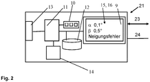
- Fig. 2 shows a schematic representation of the commissioning mode on the measuring device 1, 1a, 1b.
- the measuring device 1, 1a, 1b includes, for example, a display unit 9, by means of which the alignment measurement value 15 or possibly error messages 16 are displayed, and an input unit 10, which is used to operate the measuring device 1, 1a, 1b and the control center connected via the communication unit 13.
- the alignment measurement values 15 of the inclination sensor 14 are processed in the data processing unit 11 and stored in the storage unit 12.
- the measuring device 1, 1a, 1b communicates with other measuring devices 1 and the control center via the data interface 13 and the data line 23.
- the display unit 9, the input unit 10, the data processing unit 13, the position sensor 14 and / or the storage unit 12 can be located both in the sensor unit 8 or in the transmitter unit 21 of the measuring device 1, and can also be integrated in both at the same time.
- a correspondingly high signal-to-noise ratio is a prerequisite, which is achieved in the sensor unit 8 as a radar antenna by a high antenna gain.
- This is always accompanied by appropriate beam bundling so that interference elements such as the tank wall are not caught by the radiation lobe.
- the opening angle for the parabolic antenna at 26GHz is approximately 5 °.
- the great disadvantage of these strongly bundling antennas as sensor unit 8 is a high sensitivity with regard to their alignment with the surface of the medium 5. Only a few degrees deviation from the vertical lead to considerable signal losses.
- the sensor unit 8 can alternatively also be oriented as an antenna to its maximum signal amplitude.
- the data transfer to the service tools is too slow and the reaction to a change in inclination is so delayed that this setting option is practically unusable.
- the inclination sensor 14 can also monitor the alignment of the measuring device 1 in the operating phase and recognize whether the measuring device 1 is not exactly aligned in order to enable a highly precise measurement.
- causes of a change in inclination of the measuring device 1 can occur, for example, due to the weather due to wind and snow or modifications to the system.
- a 3-axis inclinometer is placed or installed anywhere in the measuring device 1, preferably on one of the printed circuit boards in the transmitter unit 18.
- the measuring device 1 must then be in the correct position, i.e. into the vertical, in order to record the values of the inclination sensors 14 and to store them as an alignment measurement value 15 in a storage unit 12.
- Electronic spirit levels or inclination sensors 14 or inclinometers are manufactured as micromechanical components (MEMS) and can be processed like electronic components.
- Limit values 20 for the alignment measurement value 15 are stored in the memory unit 12 of the transmitter 18, so that the measurement device 1 outputs an error message 16 when the alignment measurement value 15 is determined outside the range of these limit values 20.
- the measuring device 1, 1b it is possible for the measuring device 1, 1b to be configured automatically in accordance with its installation position or orientation.
- a point level measuring device 1b with a vibration element 8b it is important which orientation and position the fork tines of the tuning fork have as the vibration element 8b, so that an exact measurement can be carried out and the functionality and availability of the measuring device 1, 1b can be guaranteed accordingly.
- a plausibility test of the measured values and the configuration of the measuring device 1, 1b can be carried out by determining the exact alignment of the measuring device 1, 1b.
Landscapes
- Physics & Mathematics (AREA)
- Fluid Mechanics (AREA)
- General Physics & Mathematics (AREA)
- Electromagnetism (AREA)
- Thermal Sciences (AREA)
- Acoustics & Sound (AREA)
- Measurement Of Levels Of Liquids Or Fluent Solid Materials (AREA)
- Arrangements For Transmission Of Measured Signals (AREA)
Description
- Die vorliegende Erfindung betrifft ein Messgerät zur Bestimmung und/oder Überwachung des Grenzstands oder Füllstands eines Mediums in einem Behälter bestehend aus zumindest einer Sensoreinheit und einer Messumformereinheit.
- Von der Anmelderin werden auch Messgeräte unter der Bezeichnung Micropilot oder Prosonic produziert und vertrieben, welche nach dem Laufzeit-Messverfahren arbeiten und dazu dienen, einen Füllstand eines Mediums in einem Behälter zu bestimmen und/oder zu überwachen. Bei der Laufzeit-Messmethode werden beispielsweise Ultraschallwellen über einen Schallwandler oder Mikrowellen bzw. Radarwellen über eine Antenne ausgesendet und die an der Mediumsoberfläche reflektierten Echowellen werden nach der abstandsabhängigen Laufzeit des Signals wieder empfangen. Aus der Laufzeit lässt sich mit Hilfe der bekannten Ausbreitungsgeschwindigkeit der Füllstand des Mediums in einem Behälter berechnen. Die Echokurve stellt hierbei die empfangene Signalamplitude als Funktion der Zeit bzw. der Laufstrecke dar, wobei jeder Messwert der Echokurve der Amplitude eines in einem bestimmten Abstand an einer Oberfläche reflektierten Messsignals entspricht.
- Aufgrund der Messmethode nach dem Reflexionsprinzip hängt bei Messgeräten, die nach dem Laufzeit-Messverfahren arbeiten, die Güte des Messsignals bzw. der Echokurve stark von der Einbauposition ab. Zum Beispiel haben
- die Reflektionseigenschaften des Mediums,
- baulich bedingte Störelemente im Abstrahlkegel des Sendeelementes,
- Schüttkegelbildung,
- Einfüllvorrichtungen und Rührwerke im Behälter und
- die Ansatzbildung des Mediums an der Sensoreinheit
- Nach heutigem Stand der Technik muss das Bedienpersonal zum optimalen Ausrichten der Antenne bzw. des Schallwandlers die Position der Sensoreinheit schrittweise ändern und sich eine auf dem Display angezeigte Kenngröße (z.B. die Intensität der Amplitude der Füllstandsechos in dB) mit der zugehörigen eingestellten Antennen- bzw. Schallwandlerposition merken, um eine Bewertung der Messsituation im Tankbehälter vornehmen zu können. Jedoch erlaubt die bekannte Kenngröße keine umfassende Aussage über die Ausrichtung bzw. Einbausituation einer Antenne oder eines Schallwandlers in einem Behälter, meist nur die Intensität der Amplitude des Füllstandsechos, beachtet werden kann.
- Des Weiteren ist es nach heutigem Stand der Technik möglich, die Echofunktion in Abhängigkeit von der Zeit auf dem Display des Messgerätes oder einem vernetzten Service-Tool darzustellen und somit die aktuelle Messsituation bei aktueller Position der Sensoreinheit zu ermitteln. Eine solche Vorrichtung zur Visualisierung einer Echokurve oder von Historiendaten auf einer Anzeigeeinheit ist aus der Patentanmeldung
DE 100 52 836 A1 bekannt. Der Nachteil dieser Vorrichtung ist, dass es nicht möglich ist, die Messsignale unter verschiedenen Einbausituationen des Messgerätes visuell miteinander zu vergleichen und die Darstellung aufgrund der großen Datenmengen sehr langsam ist. - Eine Vorrichtung zum Verändern der Einbauposition durch eine mechanische Ausrichtvorrichtung eines Füllstandsmessgeräts ist aus der Patentanmeldung
DE 101 06 176 A1 bekannt. Ein ausrichtbares, Radar-basiertes Füllstandsmessgerät ist außerdem in der VeröffentlichungsschriftDE 10 2004 041 857 A1 beschrieben. Dort wird das Füllstandsmessgerät auf Basis der Echokurve ausgerichtet, wobei mittels eines Neigungssensors derjenige Winkel bestimmt werden kann, bei dem gemäß der Echokurve die größte Reflektion auftritt. - Ferner ist eine Vorrichtung zur Veränderung der Abstrahlcharakteristik einer Planarantenne aus der Patentanmeldung
DE 101 49 851 A1 bekannt. Eine Vorrichtung zum Erkennen einer fehlerhaften Einbausituation eines Durchflussmessgerätes in einem Messaufbau ist aus der PatentanmeldungDE 102 30 607 A1 bekannt. In dieser Offenlegungsschrift wird eine Vorrichtung vorgestellt, die die fehlerhafte Einbausituation eines Vortex - Durchflussmesseinrichtung erkennt und diese Fehlermeldung an ein Leitsystem weiterleitet. Der Nachteil dieser Beispiele einer Ausrichtvorrichtung ist, dass das Bedienpersonal zur Einstellung oder Ausrichtung des Messgerätes großes Fachwissen bzw. Know-how braucht. - Desweiteren werden von der Anmelderin Messgeräte unter dem Namen Liquiphant oder Soliphant Messgeräte produziert und vertrieben, welchen den Grenzstand eines Mediums in einem Behälter mittels der Änderung des Vibrationsverhaltens eines Schwingelementes, insbesondere eine Schwinggabel, ermitteln.
- Im Stand der Technik sind zur Bestimmung des Grenzstands bzw. Füllstands und weiterer Prozessgrößen eines Mediums so genannte Schwinggabeln (z.B.
EP 0 444 173 B1 ), Einstäbe (z.B.WO 2004/094964 A1 ) oder auch Membranschwinger als Schwingelemente bekannt. Ausgenutzt wird bei den jeweiligen Messungen, dass die Kenngrößen der mechanischen Schwingungen (Schwingungsamplitude, Resonanzfrequenz, Phasengang über Frequenz) der schwingfähigen Einheit vom Kontakt mit dem Medium und auch von dessen Eigenschaften abhängen. So nimmt beispielsweise die Frequenz oder die Amplitude der Schwingungen ab, wenn insbesondere das flüssige Medium die schwingfähige Einheit erreicht und zumindest teilweise bedeckt. Das flüssige Medium wirkt auf den schwingenden Körper des Sensors - d.h. z.B. auf die Schwinggabel bzw. den Einstab bzw. die Membran - einerseits als mitbewegte Masse, weshalb die Schwingfrequenz sinkt, und andererseits als mechanischer Dämpfer, weshalb die Schwingungsamplitude abnimmt. Daher lässt sich aus der Abnahme der Schwingungsfrequenz bzw. der Amplitude darauf schließen, dass das Medium einen von der Ausgestaltung und der Position der Anbringung der Vorrichtung abhängigen Füllstand erreicht hat. Weiterhin ist die Schwingungsfrequenz auch beispielsweise von der Viskosität des Mediums abhängig (siehe z.B.EP 1 325 301 ). - Zur Anregung der jeweiligen mechanisch schwingfähigen Einheiten werden oft piezoelektrische Elemente verwendet, welche umgekehrt auch die mechanischen Schwingungen in elektrische Signale umwandeln. Weiterhin ist für bestimmte Anwendungen auch eine elektromagnetische Anregung der schwingfähigen Einheit möglich.
- Im Stand der Technik gibt es Ansätze, die Sensoreinheiten einer Selbstüberwachung zu unterziehen, d.h. zu testen, ob der Sensor bzw. einzelne Bestandteile des Sensors in Ordnung sind. Eine Problematik besteht dabei darin, dass insbesondere die Funktionsfähigkeit der schwingfähigen Einheit, d.h. dem Bestandteil, welches mit dem Medium in Kontakt tritt und somit den größten Belastungen ausgesetzt ist, in den bekannten Messverfahren nicht überprüft wird. Jedoch ist es für die exakte Messung notwendig die Einbauposition der Sensoreinheit sicher zu stellen.
- Der Erfindung liegt die Aufgabe zugrunde, eine Vorrichtung zur Ermittlung und Überwachung der optimierten Ausrichtung des Messgerätes aufzuzeigen.
- Gelöst wird diese Aufgabe durch einen Vorrichtung gemäß Anspruch 1.
- Weitere Ausgestaltungen sind in den Unteransprüchen 2 - 7 ausgeführt.
- Die Erfindung wird anhand der nachfolgenden Zeichnungen näher erläutert. Zur Vereinfachung sind in den Zeichnungen identische Teile mit dem gleichen Bezugszeichen versehen worden. Es zeigt:
- Fig. 1
- ein Ausführungsbeispiel des erfindungsgemäßen Messgerätes am Behälter, und
- Fig. 2
- ein Ausführungsbeispiel des erfindungsgemäßen Messumformereinheit des Messgerätes.
- In
Fig. 1 ist auf einem Behälter 2 in einem Stutzen 4 ein Messgerät 1a montiert, das nach dem Laufzeit-Messverfahren den Füllstand 28 eines Mediums 5 bzw. Füllguts 5 im Behälter 2 ermittelt. - Das Messgerät 1, 1a wird in den meisten Anwendungen über einen Flansch 6 in einem Stutzen 4 am Behälter 2 befestigt. Es besteht aber auch die Möglichkeit, das Messgerät 1, 1b über eine Einschraubung 7 am Behälter 2 zu befestigen. In der
Fig. 1 ist die Möglichkeit einer mechanischen Ausrichtung der Sensoreinheit 8 über eine mechanische Ausrichtvorrichtung 3 als druck- und gasdichtes Kugelgelenk aufgezeigt, jedoch sind auch andere Ausrichtvorrichtungen 3, wie z.B. Drehkeilflansche, usw. als Ausrichtvorrichtung 3 einsetzbar. - In der Darstellung ist ein Messgerät 1 aufgezeigt, das sich grundsätzlich aus einer Sensoreinheit 8, die sich im Behälter 2 befindet und einer Messumformereinheit 21 die sich in einem Gehäuse außerhalb des geschlossenen Behälters 2 zusammensetzt. Diese Sensoreinheit 8 und hier speziell ein Schallwandler 8a ist über einen Stutzen 4 in den Behälter 2 eingebracht und durch einen beidseitigen Flansch 6 am Behälter 2 befestigt. Eine mechanische Ausrichtvorrichtung 3 ist in dem Bereich, in dem das Messgerät 1a am Behälter 2 befestigt ist, ausgebildet, welche über einen Antrieb 19 automatisiert verstellt werden kann. Das Messgerät 1a besitzt einen Versorgungsleitung 24 und einen Feldbus 23. In der Messumformereinheit 21 ist ein Neigungssensor 14 integriert, der einen Ausrichtungsmesswert 15 ermittelt. Dieser ermittelte Ausrichtungsmesswert 15 werden auf der Anzeigeeinheit 9 des Messgerätes 1, 1a, 1b visuelle oder akustisch zur Anzeige gebracht, und über die Eingabeeinheit 10 wird die Bedienung des Messgerätes 1, 1a, 1b vorgenommen werden.
- Das Messgerät 1, 1a, 1b bzw. die Sensoreinheit 8 wird mit der mechanischen Ausrichtvorrichtung 3 über einen Antrieb 19 von der ersten Einbauposition 22a in die zweite Einbauposition 22b verstellt. Die Änderung der Neigung des Messgeräts 1 wird über den integrierten Neigungssensor 14 ermittelt und als Ausrichtungsmesswert 15 beispielsweise auf einem Display als Anzeigeeinheit 9 visuell dargestellt. Desweiteren ist es möglich, dass die Ausrichtung des Messgeräts 1, 1a, 1b anhand der Tonhöhe eines akustischen Tonsignals von der Anzeigeeinheit 9 dem Bediener signalisiert wird. Bei dieser Ausgestaltung ist es notwendig, dass ein Tongeber in der Anzeigeeinheit 9 vorhanden ist.
- Die Energieversorgung des Messgerätes 1 selbst erfolgt über eine Versorgungsleitung 24, und die Kommunikation mit einer entfernten Leitstelle oder mit anderen Messgeräten 1 wird über einen Feldbus 23, der alle bekannten Kommunikationsstandards, wie z.B. PROFIBUS-PA oder FOUNDATION FIELDBUS, unterstützt, erreicht. Insbesondere ist vorgesehen, das Messgerät 1 über den Feldbus 23 mit der nötigen Energie zu versorgen. Hierzu ist das Messgerät 1 bevorzugt nach den Standards und Vorschriften als ein 4-20 mA Zweileiter-Messgerät ausgelegt. Durch die Kommunikationsanbindung des Inbetriebnahmegerätes 8 bzw. des Messgerätes 1 über einen Feldbus 23 an eine entfernte Leitstelle ist auch ein automatisierter Ausrichtvorgang des Messgerätes 1, der von der Leitstelle aus gestartet und bewertet wird, möglich.
- Zur Funktionsweise des Füllstandsmessgerätes 1a ist folgendes zu sagen: Vom Messgerät 1 bzw. von der Sensoreinheit 8 wird ein breitbandiges Mikrowellen- oder Ultraschall-Impulssignal 27 in den Messraum bzw. in den Behälter 2 ausgesendet. An den im Strahlungskegel der Sensoreinheit 8 befindlichen Oberflächen von Objekten, z.B. Störelemente 23 oder Füllgut 5, werden die Wellen 27 nach dem Reflexionsgesetz im gleichen Winkel zum Lot der Oberfläche wieder reflektiert. Dadurch wird an jeder Oberfläche, die im Abstrahlungskegel der Sensoreinheit 8 liegt, abhängig vom Auftreffwinkel und vom Material des Reflektors ein Reflektionssignal 27 in die Sensoreinheit 8 zurückreflektiert. Aus der Laufzeit des von der Oberfläche des Füllguts 5 zurückreflektierten Messsignals 27 wird der Füllstand 28 des Füllguts 5 berechnet. Die Ausrichtung der Sensoreinheit 8 eine Füllstandsmessgeräts 1a ist übrigens auch beim FMCW - Verfahren notwendig und wird auch dort durchgeführt.
- Über eine Auswahlfunktion in der Bedienerführung des Messgerätes 1 oder bei der erstmaligen Inbetriebnahme schaltet sich das Messgerät 1 in den Betriebsmodus, indem die Ausrichtung der Sensoreinheit 8 ermöglicht wird.
-
Fig. 2 zeigt eine schematische Darstellung des Inbetriebnahmemodus am Messgerät 1, 1a, 1b. Das Messgerät 1, 1a, 1b beinhaltet beispielsweise eine Anzeigeeinheit 9, über welche der Ausrichtungsmesswert 15 oder gegebenenfalls Fehlermeldungen 16 angezeigt werden und eine Eingabeeinheit 10, die zur Bedienung des Messgeräts 1, 1a, 1b und der über die Kommunikationseinheit 13 verbundenen Leitstelle verwendet wird. Die Ausrichtungsmesswerte 15 des Neigungssensors 14 werden in der Datenverarbeitungseinheit 11 verarbeitet und in der Speichereinheit 12 abgelegt. Über die Datenschnittstelle 13 und über die Datenleitung 23 kommuniziert das Messgerät 1, 1a, 1b mit anderen Messgeräten 1 und der Leistelle. Die Kommunikation zwischen dem Messgerät 1, 1a, 1b und der Leitstelle kann gleichfalls mit der Energieversorgung des Messgeräts 1, 1a, 1b über die gleiche Datenleitung 23, 24 in einer Zweileiter- oder Vierleitertechnik erfolgen. Möglich ist außerdem eine kabellose Kommunikation über Funk. Die Anzeigeeinheit 9, die Eingabeeinheit 10, die Datenverarbeitungseinheit 13, der Positionssensor 14 und/oder die Speichereinheit 12 können sich sowohl in dem Sensoreinheit 8 oder in der Messumformereinheit 21 des Messgerät 1 befinden, als auch in beiden gleichzeitig integriert sein. - Für eine hohe Messgenauigkeit ist ein entsprechend hoher Signal-zu-Rausch-Abstand Voraussetzung, der bei der Sensoreinheit 8 als Radarantenne durch einen hohen Antennengewinn erzielt wird. Damit geht immer eine entsprechende Strahlbündelung einher, damit Störelemente wie z.B. die Tankwand nicht von der Strahlungskeule erfasst werden. Beispielsweise beträgt der Öffnungswinkel bei der Parabolantenne bei 26GHz ungefähr 5°. Der große Nachteil dieser stark bündelnden Antennen als Sensoreinheit 8 ist eine hohe Empfindlichkeit bezüglich ihrer Ausrichtung auf die Oberfläche des Mediums 5. Nur wenige Grad Abweichung von der Senkrechten führen zu erheblichen Signalverlusten.
- Wie schon beschrieben, kann alternativ die Sensoreinheit 8 als Antenne auch auf ihre maximale Signalamplitude ausgerichtet werden. Dabei ist aber die Datenübertragung zu den Servicetools zu langsam und die Reaktion auf eine Neigungsänderung so stark verzögert, dass diese Einstellmöglichkeit praktisch nicht zu gebrauchen ist.
- Zukünftige RADAR-Füllstandsmessgeräte 1, 1a werden voraussichtlich mit Frequenzen bis zu 80 GHz arbeiten wodurch noch höhere Bündelung des Strahlungsprofils der Antenne erreicht werden. Jedoch ist es hierbei die exakte Ausrichtung des Messgeräts 1, 1a unbedingt notwendig um Störeinflüsse zu vermeiden.
- Der Neigungssensor 14 kann darüber hinaus auch in der Betriebsphase des Messgeräts 1 dessen Ausrichtung überwachen und erkennen, ob das Messgerät 1 nicht exakt ausgerichtet ist, um eine hochgenaue Messung zu ermöglichen. Ursachen für eine Neigungsänderung des Messgeräts 1 kann beispielsweise witterungsbedingt durch Wind und Schnee oder Umbauten an der Anlage erfolgen.
- Als Neigungssensor 14 wird beispielsweise ein 3-Achseninklinometer an beliebiger Stelle im Messgerät 1 platziert oder eingebaut, vorzugsweise auf einer der Leiterplatten in der Messumformereinheit 18. Das Messgerät 1 muss dann einmal in die richtige Lage, d.h. in die Senkrechte, gebracht werden um die Werte der Neigungssensoren 14 zu erfassen und als Ausrichtungsmesswert 15 in einer Speichereinheit 12 zu speichern Elektronische Wasserwaagen bzw. Neigungssensoren 14 bzw. Inklinometer werden als mikromechanische Bauteile (MEMS) hergestellt und können wie elektronische Bauteile verarbeitet werden.
- In der Speichereinheit 12 der Messumformereinheit 18 sind Grenzwerte 20 für den Ausrichtungsmesswert 15 abgelegt, so dass das Messgerät 1 bei einem ermittelten Ausrichtungsmesswert 15 außerhalb des Bereichs dieser Grenzwerte 20 eine Fehlermeldung 16 ausgibt.
- Beispielsweise ist es möglich, dass das Messgerät 1,1b entsprechend seiner Einbaulage bzw. Ausrichtung entsprechend automatisch konfiguriert wird. Bei einem Grenzstandmessgerät 1b mit einem Schwingungselement 8b ist es wichtig, welche Ausrichtung und Position die Gabelzinken der Schwinggabel als Schwingelement 8b besitzen, damit eine exakte Messung erfolgen kann und die Funktionstüchtigkeit und Verfügbarkeit des Messgeräts 1, 1b entsprechend gewährleistet werden kann. Desweiteren kann über die Ermittlung der exakten Ausrichtung des Messgeräts 1, 1b ein Plausibilitätstest der Messwerte und der Konfiguration des Messgeräts 1, 1b erfolgen.
-
- 1
- Messgerät
- 1a
- Füllstandsmessgerät
- 1b
- Grenzstandmessgerät
- 2
- Behälter
- 3
- Ausrichtvorrichtung
- 4
- Stutzen
- 5
- Füllgut bzw. Medium
- 6
- Flansch
- 7
- Einschraubung
- 8
- Sensoreinheit
- 8a
- Ultraschallsensor
- 8b
- Schwingeinheit
- 9
- Anzeigeeinheit
- 10
- Eingabeeinheit
- 11
- Datenverarbeitungseinheit
- 12
- Speichereinheit
- 13
- Kommunikationseinheit
- 14
- Neigungssensor, Positionssensor
- 15
- Ausrichtungsmesswert
- 16
- Fehlermeldung
- 17
- Störecho, Störsignale
- 18
- Messumformereinheit
- 19
- Antrieb
- 20
- Grenzwert
- 21
- 22
- Einbauposition
- 22a
- Erste Einbauposition
- 22b
- Zweite Einbauposition
- 23
- Feldbus
- 24
- Versorgungsleitung
- 27
- Messsignal
- 28
- Füllstand
Claims (7)
- Messgeräts zur Bestimmung und/oder Überwachung des Grenzstands oder Füllstands (18) eines Mediums in einem Behälter (2) bestehend aus zumindest einer Sensoreinheit (8) und einer Messumformereinheit (21),
wobei zumindest ein Neigungssensor (14) in dem Messgerät (1) integriert ist, der die Ausrichtung des Messgeräts (1) und/oder der Sensoreinheit (8) an dem Behälter (2) ermittelt,
wobei der Neigungssensor (14) dermaßen ausgestaltet ist, dass die Ausrichtung des Messgeräts (1) und/oder der Sensoreinheit (8) als zumindest ein Ausrichtungsmesswert (15) in der Betriebsphase des Messgeräts (1) ständig überwacht wird,
dadurch gekennzeichnet,
dass die Messumformereinheit (21) eine Speichereinheit (12) aufweist, in der Grenzwerte für den Ausrichtungsmesswert (15) abgelegt sind und
dass das Messgerät (1) eingerichtet ist, bei einem ermittelten Ausrichtungsmesswert (15) außerhalb des Bereichs dieser Grenzwerte eine Fehlermeldung (16) auszugeben. - Vorrichtung nach Anspruch 1,
dadurch gekennzeichnet,
dass der Neigungssensor (14) in der Sensoreinheit (8) ausgestaltet ist. - Messgerät nach Anspruch 1,
dadurch gekennzeichnet,
dass der Neigungssensor (14) in der Messumformereinheit (21) integriert ist. - Messgerät nach zumindest einem der Ansprüche 1 bis 3,
dadurch gekennzeichnet,
dass der Neigungssensor (14) dermaßen ausgestaltet ist, dass die Ausrichtung des Messgeräts (1) und/oder der Sensoreinheit (8) als zumindest ein Ausrichtungsmesswert (15) bei der Inbetriebnahme des Messgeräts (1) ermittelt werden. - Messgerät nach zumindest einem der Ansprüche 1 oder 4,
dadurch gekennzeichnet,
dass eine in der Messumformereinheit (21) integrierte Anzeigeeinheit (9) eingerichtet ist, diesen Ausrichtungsmesswert (15) und/oder die Fehlermeldung (16) zur Ermittlung der Ausrichtung visuell oder akustisch anzuzeigen - Messgerät nach zumindest einem der Ansprüche 1 oder 4,
dadurch gekennzeichnet,
dass eine in der Messumformereinheit (21) integrierte Kommunikationseinheit (13) eingerichtet ist, diesen Ausrichtungsmesswert (15) und/oder die Fehlermeldung (16) über einen Feldbus (23) an eine entfernte Leitstelle zu übertragen. - Messgerät nach zumindest einem der vorhergehenden Ansprüche,
dadurch gekennzeichnet,
dass eine automatische Ausrichtvorrichtung (3) im Messgerät (1) integriert ist, dass ein Antrieb (19) vorgesehen ist, der eingerichtet ist, mittels der Ausrichtvorrichtung (3) die Einbauposition (22, 22a, 22b) des Messgerätes (1) und/oder der Sensoreinheit (8) automatisiert anzusteuern
Applications Claiming Priority (2)
| Application Number | Priority Date | Filing Date | Title |
|---|---|---|---|
| DE102010064394A DE102010064394A1 (de) | 2010-12-30 | 2010-12-30 | Verfahren und Vorrichtung zum Ausrichten eines Messgerätes |
| PCT/EP2011/071465 WO2012089438A1 (de) | 2010-12-30 | 2011-12-01 | Verfahren und vorrichtung zum ausrichten eines messgerätes |
Publications (2)
| Publication Number | Publication Date |
|---|---|
| EP2659238A1 EP2659238A1 (de) | 2013-11-06 |
| EP2659238B1 true EP2659238B1 (de) | 2020-04-01 |
Family
ID=45420578
Family Applications (1)
| Application Number | Title | Priority Date | Filing Date |
|---|---|---|---|
| EP11802303.5A Active EP2659238B1 (de) | 2010-12-30 | 2011-12-01 | Vorrichtung zum ausrichten eines messgerätes |
Country Status (6)
| Country | Link |
|---|---|
| US (1) | US9989401B2 (de) |
| EP (1) | EP2659238B1 (de) |
| JP (1) | JP5833668B2 (de) |
| CN (1) | CN103348222A (de) |
| DE (1) | DE102010064394A1 (de) |
| WO (1) | WO2012089438A1 (de) |
Cited By (1)
| Publication number | Priority date | Publication date | Assignee | Title |
|---|---|---|---|---|
| EP4361575A1 (de) * | 2022-10-28 | 2024-05-01 | Biotage AB | Verfahren zur überwachung des flüssigkeitsgehalts |
Families Citing this family (44)
| Publication number | Priority date | Publication date | Assignee | Title |
|---|---|---|---|---|
| DE102010064394A1 (de) * | 2010-12-30 | 2012-07-05 | Endress + Hauser Gmbh + Co. Kg | Verfahren und Vorrichtung zum Ausrichten eines Messgerätes |
| EP2811269A1 (de) * | 2013-06-06 | 2014-12-10 | VEGA Grieshaber KG | Multigrenzstandmessgerät |
| DE102013019524B3 (de) * | 2013-09-05 | 2015-01-29 | Krohne Messtechnik Gmbh | Verfahren zur Bestimmung eines Füllstands eines Mediums und Vorrichtung zur Bestimmung eines Füllstands eines Mediums |
| DE102013113766A1 (de) * | 2013-12-10 | 2015-06-11 | Endress + Hauser Gmbh + Co. Kg | Vorrichtung zur Messung des Füllstands eines Füllguts in einem Behälter |
| KR102007927B1 (ko) * | 2014-02-11 | 2019-08-06 | 베가 그리이샤버 카게 | 충전 수위 및 토폴로지의 판단 |
| JP2017506746A (ja) * | 2014-02-11 | 2017-03-09 | ヴェガ グリースハーバー カーゲー | 容器に充填した材料表面トポロジーの決定 |
| US10254145B2 (en) | 2014-02-21 | 2019-04-09 | Vega Grieshaber Kg | Level indicator featuring optimized energy supply |
| WO2015139756A1 (de) | 2014-03-20 | 2015-09-24 | Vega Grieshaber Kg | Tragbare vorrichtung zum ausrichten eines füllstandmessgerätes an einem behälter |
| DE102014104747A1 (de) * | 2014-04-03 | 2015-10-08 | Pfeiffer Vacuum Gmbh | Verfahren und System zur Ermittlung und Bewertung der Einbauorientierung einer Einrichtung |
| RU2561309C1 (ru) * | 2014-04-22 | 2015-08-27 | Закрытое акционерное общество ЛИМАКО | Радиолокационный уровнемер |
| CN106164626A (zh) * | 2014-06-03 | 2016-11-23 | Vega格里沙贝两合公司 | 容器轮廓和缺陷轮廓的识别 |
| US9658096B2 (en) * | 2014-06-30 | 2017-05-23 | Rosemount Tank Radar Ab | Radar level gauge inclination system |
| US9841307B2 (en) * | 2014-09-30 | 2017-12-12 | Rosemount Inc. | Multivariable guided wave radar probe |
| DE102014118862B4 (de) * | 2014-12-17 | 2021-12-09 | Endress+Hauser SE+Co. KG | System zur Kalibrierung eines Abstandsmessgeräts |
| EP3054271B1 (de) * | 2015-02-03 | 2017-06-28 | VEGA Grieshaber KG | Grenzstandschalter mit integriertem Lagesensor |
| DE102015202448A1 (de) * | 2015-02-11 | 2016-08-11 | Vega Grieshaber Kg | Auswerteverfahren für einen TDR-Grenzstandschalter |
| EP3073229B1 (de) * | 2015-03-27 | 2022-06-22 | VEGA Grieshaber KG | Radar-füllstandmessgerät mit integriertem grenzstandsensor |
| DE102015110865A1 (de) * | 2015-07-06 | 2017-01-12 | Thyssenkrupp Ag | Trennvorrichtung und Verfahren zum Detektieren einer Stoffansammlung in einer solchen Trennvorrichtung |
| DE102015122284A1 (de) * | 2015-12-18 | 2017-06-22 | Endress + Hauser Gmbh + Co. Kg | Elektronikeinheit mit Diagnosefunktion |
| FR3048774B1 (fr) * | 2016-03-08 | 2019-12-20 | Lionel Lecrosnier | Dispositif de controle du volume d'un produit contenu dans un reservoir |
| DE102016106051B3 (de) * | 2016-04-03 | 2017-09-21 | Krohne Messtechnik Gmbh | Vorrichtung zur Erfassung einer Schüttgutoberfläche |
| CN105806446A (zh) * | 2016-04-29 | 2016-07-27 | 大唐环境产业集团股份有限公司 | 一种组合式的料位测量装置 |
| CN105928588A (zh) * | 2016-04-29 | 2016-09-07 | 大唐环境产业集团股份有限公司 | 一种防堵的多级组合式料位测量装置 |
| CN105865579A (zh) * | 2016-04-29 | 2016-08-17 | 大唐环境产业集团股份有限公司 | 一种防堵的双级料位测量装置 |
| CN107796483A (zh) * | 2016-09-07 | 2018-03-13 | 桓达科技股份有限公司 | 远距自动强化信噪比的液位感测装置 |
| JP6312222B2 (ja) * | 2016-09-26 | 2018-04-18 | 桓達科技股▲ふん▼有限公司FINETEK Co.,Ltd. | 液位センシング装置 |
| DE102016119149B4 (de) * | 2016-10-07 | 2020-12-31 | Finetek Co., Ltd | Vorrichtung zur Füllstandsmessung über große Entfernung mit automatischer Verbesserung des Signal-Rausch-Verhältnisses |
| DE102017109316A1 (de) * | 2017-05-02 | 2018-11-08 | Endress+Hauser SE+Co. KG | Verfahren zur Bestimmung und/oder Überwachung des Füllstands |
| JP6866759B2 (ja) * | 2017-05-16 | 2021-04-28 | 株式会社Soken | 液面検出装置 |
| RU2653578C1 (ru) * | 2017-06-08 | 2018-05-11 | Акционерное общество "ЛИМАКО" | Радиолокационный уровнемер для измерения объема сыпучих продуктов в резервуарах |
| JP6472566B1 (ja) * | 2018-09-04 | 2019-02-20 | ムサシノ機器株式会社 | 組成比率推定装置、組成比率推定方法、組成比率推定プログラム、および液面計 |
| GB2578607A (en) * | 2018-10-31 | 2020-05-20 | Hwm Water Ltd | Level sensing apparatus |
| DE102018128253A1 (de) * | 2018-11-12 | 2020-05-14 | Endress+Hauser SE+Co. KG | Verfahren zum Ausrichten eines Radar-basierten Füllstandsmessgerätes |
| DE102018219366A1 (de) * | 2018-11-13 | 2020-05-14 | Vega Grieshaber Kg | Sensorvorrichtung und Sensorvorrichtungs-Halterung |
| DE102019202137A1 (de) * | 2019-02-18 | 2020-08-20 | Fraunhofer-Gesellschaft zur Förderung der angewandten Forschung e.V. | Winkelkorrigierte füllstandsermittlung |
| KR102037132B1 (ko) * | 2019-02-27 | 2019-10-28 | 안민헌 | 분리형 레이더 수위 측정 장치 |
| CN110186539B (zh) * | 2019-06-24 | 2020-10-27 | 中国石油大学(北京) | 流量计检测安装用法兰的对中连接机构 |
| DE102019130530A1 (de) * | 2019-11-12 | 2021-05-12 | Vega Grieshaber Kg | Messsystem und Verfahren zur Installation und/oder Wartung des Messsystems |
| GB201916592D0 (en) * | 2019-11-14 | 2020-01-01 | Rosemount Measurement Ltd | Improvements in or relating to field devices |
| CN111457990A (zh) * | 2020-04-30 | 2020-07-28 | 国电锅炉压力容器检验有限公司 | 一种他比式涡流线圈组液位计及液位测量方法 |
| DE102020206108A1 (de) | 2020-05-14 | 2021-11-18 | Vega Grieshaber Kg | Füllstandmessanordnung zum Bestimmen eines Füllstands oder Volumens eines Füllguts in einem mobilen Behälter |
| AT523436B1 (de) * | 2020-05-20 | 2021-08-15 | Rosenberger Telematics Gmbh | Verfahren zum Bestimmen der Schüttgutmenge in einem stehenden Behälter |
| DE102021123735A1 (de) | 2021-09-14 | 2023-03-16 | Endress+Hauser SE+Co. KG | Füllstandsmessgerät |
| JP7199112B1 (ja) | 2021-10-22 | 2023-01-05 | 株式会社マツシマメジャテック | 測定器具 |
Family Cites Families (22)
| Publication number | Priority date | Publication date | Assignee | Title |
|---|---|---|---|---|
| DE3931453C1 (de) | 1989-09-21 | 1991-02-28 | Endress U. Hauser Gmbh U. Co, 7864 Maulburg, De | |
| US5184510A (en) * | 1991-12-23 | 1993-02-09 | Ford Motor Company | Liquid level sensor |
| JP2870346B2 (ja) * | 1992-03-23 | 1999-03-17 | 住友金属工業株式会社 | 竪型炉の装入物プロフィール測定方法および測定装置 |
| DE29825191U1 (de) | 1998-08-27 | 2005-12-08 | Bartec Gmbh | Vorrichtung zur Volumenbestimmung |
| DE10050299A1 (de) | 2000-10-10 | 2002-04-11 | Endress Hauser Gmbh Co | Vorrichtung zur Bestimmung und/oder Überwachung der Viskosität eines Mediums in einem Behälter |
| DE10052836A1 (de) | 2000-10-24 | 2002-05-16 | Endress Hauser Gmbh Co | Vorrichtung zur Bestimmung und/oder Überwachung einer Prozeßvariablen |
| US6634234B1 (en) * | 2001-02-10 | 2003-10-21 | Vega Grieshaber Kg | Adjustable measurement head and a level measurement device and method employing it |
| DE10106176B4 (de) | 2001-02-10 | 2007-08-09 | Vega Grieshaber Kg | Ausrichtbarer Messkopf und diesen verwendende Füllstandsmessvorrichtung und -verfahren |
| DE10149851A1 (de) | 2001-10-10 | 2003-04-24 | Endress & Hauser Gmbh & Co Kg | Vorrichtung zur Bestimmung des Füllstandes eines Füllguts in einem Behälter |
| DE10230607A1 (de) | 2002-07-08 | 2004-02-05 | Abb Patent Gmbh | Verfahren zur Überwachung einer Messeinrichtung, insbesondere einer Durchflussmesseinrichtung, sowie eine Messeinrichtung selbst |
| DE10242500A1 (de) * | 2002-09-12 | 2004-03-18 | Endress + Hauser Gmbh + Co. Kg | Ausrichtvorrichtung für ein Meßgerät |
| JP2004205147A (ja) | 2002-12-26 | 2004-07-22 | Iseki & Co Ltd | 穀物乾燥機 |
| DE10318705A1 (de) | 2003-04-24 | 2004-11-18 | Endress + Hauser Gmbh + Co. Kg | Vorrichtung zur Bestimmung und/oder Überwachung mindestens einer physikalischen oder chemischen Prozessgröße eines Mediums |
| DE10361884B3 (de) * | 2003-12-19 | 2005-08-11 | Siemens Ag | Vorrichtung und Verfahren zur Überwachung eines Gasvolumens in einer mit Flüssigkeit befüllten Anlage |
| DE102004041857A1 (de) * | 2004-08-27 | 2006-03-02 | Endress + Hauser Gmbh + Co. Kg | Verfahren und Vorrichtung zum Ausrichten eines Messgerätes |
| EP1816449B1 (de) * | 2006-02-06 | 2019-04-10 | Hach Lange GmbH | Schlammspiegelsonde, Sedimentationsanlage und Verfahren zur Bestimmung des Schlammspiegels |
| US20080100501A1 (en) * | 2006-10-26 | 2008-05-01 | Olov Edvardsson | Antenna for a radar level gauge |
| GB0714060D0 (en) * | 2007-07-20 | 2007-08-29 | Airbus Uk Ltd | Ultrasonic fluid measurement method |
| JP2009139212A (ja) | 2007-12-06 | 2009-06-25 | Ricoh Elemex Corp | 超音波式液面計 |
| DE102009001010B4 (de) * | 2008-12-30 | 2023-06-15 | Endress+Hauser SE+Co. KG | Verfahren zur Ermittlung und Überwachung des Füllstands eines Mediums in einem Behälter nach einem Laufzeitmessverfahren |
| US8677639B2 (en) * | 2010-10-21 | 2014-03-25 | K-2 Corporation | Ski pole with inclinometer |
| DE102010064394A1 (de) * | 2010-12-30 | 2012-07-05 | Endress + Hauser Gmbh + Co. Kg | Verfahren und Vorrichtung zum Ausrichten eines Messgerätes |
-
2010
- 2010-12-30 DE DE102010064394A patent/DE102010064394A1/de not_active Withdrawn
-
2011
- 2011-12-01 WO PCT/EP2011/071465 patent/WO2012089438A1/de not_active Ceased
- 2011-12-01 CN CN201180063700XA patent/CN103348222A/zh active Pending
- 2011-12-01 US US13/976,604 patent/US9989401B2/en active Active
- 2011-12-01 EP EP11802303.5A patent/EP2659238B1/de active Active
- 2011-12-01 JP JP2013546640A patent/JP5833668B2/ja active Active
Non-Patent Citations (1)
| Title |
|---|
| None * |
Cited By (1)
| Publication number | Priority date | Publication date | Assignee | Title |
|---|---|---|---|---|
| EP4361575A1 (de) * | 2022-10-28 | 2024-05-01 | Biotage AB | Verfahren zur überwachung des flüssigkeitsgehalts |
Also Published As
| Publication number | Publication date |
|---|---|
| US9989401B2 (en) | 2018-06-05 |
| CN103348222A (zh) | 2013-10-09 |
| DE102010064394A1 (de) | 2012-07-05 |
| WO2012089438A1 (de) | 2012-07-05 |
| US20130269414A1 (en) | 2013-10-17 |
| JP2014504719A (ja) | 2014-02-24 |
| JP5833668B2 (ja) | 2015-12-16 |
| EP2659238A1 (de) | 2013-11-06 |
Similar Documents
| Publication | Publication Date | Title |
|---|---|---|
| EP2659238B1 (de) | Vorrichtung zum ausrichten eines messgerätes | |
| EP2035790B1 (de) | Vorrichtung zur ermittlung und/oder überwachung des füllstandes eines mediums | |
| DE102007042043A1 (de) | Vorrichtung zur Ermittlung und Überwachung des Füllstands eines Füllguts in einem Behälter | |
| EP0903563B1 (de) | Vorrichtung zur Feststellung und/oder Überwachung eines vorbestimmten Füllstands in einem Behälter | |
| EP2260273B1 (de) | Verfahren zur bestimmung und/oder überwachung des füllstands eines mediums in einem behälter | |
| EP4214477B1 (de) | Kalibration und fertigung von modular aufgebauten füllstandsmessgeräten | |
| EP2623944B1 (de) | Nach dem Radar-Prinzip arbeitendes Füllstandmesssystem | |
| DE102010038732A1 (de) | Vorrichtung und Verfahren zur Sicherung der Befestigung des koaxial um die Messsonde angeordnete Rohres einer Messsondeneinheit des Füllstandsmessgerät an einem Prozessanschlusselement | |
| DE102004041857A1 (de) | Verfahren und Vorrichtung zum Ausrichten eines Messgerätes | |
| EP3540384A1 (de) | Radarfüllstandmessgerät, verfahren zur inbetriebnahme eines radarfüllstandmessgerätes und verfahren zum betreiben eines radarfüllstandmessgerätes | |
| WO2012123344A1 (de) | Verfahren zur kalibrierung eines ultraschall - füllstandsensors | |
| WO2007093197A1 (de) | Vibrationsgrenzschalteranordenung bzw. verfahren zum korrigieren eines vibrationsgrenzschalter-schaltpunktes | |
| DE3348119C2 (en) | Device for ascertaining and/or monitoring a predetermined filling level in a container | |
| EP3314210B1 (de) | Feldgerät mit kompensationsschaltung zur eliminierung von umgebungseinflüssen | |
| EP3470802B1 (de) | Füllstandsmessgerät und verfahren für die bestimmung der menge an schüttgut in einem behälter | |
| DE19817378A1 (de) | Füllstandsmeßvorrichtung | |
| EP1800093B1 (de) | Vorrichtung zur bestimmung und/oder überwachung einer prozessgrösse eines mediums | |
| DE102022110405B3 (de) | Vibronischer Grenzstandsensor mit Schalldetektor | |
| EP3812713B1 (de) | Messeinrichtung und verfahren zum betrieb einer messeinrichtung, die zur ermittlung einer fluidgrösse dient | |
| EP1899690A1 (de) | Verfahren zur ermittlung des füllstands eines mediums in einem behälter nach der laufzeitmessmethode | |
| WO2004010092A2 (de) | Verfahren zur herstellung eines gehäuses für einen gekapselten sensor und entsprechendes gehäuse | |
| DE102004059050A1 (de) | Vorrichtung zur Bestimmung und/oder Überwachung einer Prozessgröße | |
| DE102015007698B4 (de) | Sensorvorrichtung und Verfahren zur Distanzmessung mittels Ultraschall | |
| DE102007023437B4 (de) | Vorrichtung zur Bestimmung und/oder Überwachung einer Prozessgröße | |
| WO2022089720A1 (de) | Topologieerfassendes füllstandmessgerät |
Legal Events
| Date | Code | Title | Description |
|---|---|---|---|
| PUAI | Public reference made under article 153(3) epc to a published international application that has entered the european phase |
Free format text: ORIGINAL CODE: 0009012 |
|
| 17P | Request for examination filed |
Effective date: 20130604 |
|
| AK | Designated contracting states |
Kind code of ref document: A1 Designated state(s): AL AT BE BG CH CY CZ DE DK EE ES FI FR GB GR HR HU IE IS IT LI LT LU LV MC MK MT NL NO PL PT RO RS SE SI SK SM TR |
|
| DAX | Request for extension of the european patent (deleted) | ||
| RAP1 | Party data changed (applicant data changed or rights of an application transferred) |
Owner name: ENDRESS+HAUSER SE+CO. KG |
|
| STAA | Information on the status of an ep patent application or granted ep patent |
Free format text: STATUS: EXAMINATION IS IN PROGRESS |
|
| 17Q | First examination report despatched |
Effective date: 20190513 |
|
| REG | Reference to a national code |
Ref country code: DE Ref legal event code: R079 Ref document number: 502011016587 Country of ref document: DE Free format text: PREVIOUS MAIN CLASS: G01F0023284000 Ipc: G01F0025000000 |
|
| GRAP | Despatch of communication of intention to grant a patent |
Free format text: ORIGINAL CODE: EPIDOSNIGR1 |
|
| STAA | Information on the status of an ep patent application or granted ep patent |
Free format text: STATUS: GRANT OF PATENT IS INTENDED |
|
| RIC1 | Information provided on ipc code assigned before grant |
Ipc: G01F 23/00 20060101ALI20191016BHEP Ipc: G01F 23/296 20060101ALN20191016BHEP Ipc: G01F 23/284 20060101ALI20191016BHEP Ipc: G01F 25/00 20060101AFI20191016BHEP |
|
| RIC1 | Information provided on ipc code assigned before grant |
Ipc: G01F 23/296 20060101ALN20191023BHEP Ipc: G01F 25/00 20060101AFI20191023BHEP Ipc: G01F 23/284 20060101ALI20191023BHEP Ipc: G01F 23/00 20060101ALI20191023BHEP |
|
| INTG | Intention to grant announced |
Effective date: 20191114 |
|
| GRAS | Grant fee paid |
Free format text: ORIGINAL CODE: EPIDOSNIGR3 |
|
| GRAA | (expected) grant |
Free format text: ORIGINAL CODE: 0009210 |
|
| STAA | Information on the status of an ep patent application or granted ep patent |
Free format text: STATUS: THE PATENT HAS BEEN GRANTED |
|
| AK | Designated contracting states |
Kind code of ref document: B1 Designated state(s): AL AT BE BG CH CY CZ DE DK EE ES FI FR GB GR HR HU IE IS IT LI LT LU LV MC MK MT NL NO PL PT RO RS SE SI SK SM TR |
|
| REG | Reference to a national code |
Ref country code: GB Ref legal event code: FG4D Free format text: NOT ENGLISH |
|
| REG | Reference to a national code |
Ref country code: AT Ref legal event code: REF Ref document number: 1251964 Country of ref document: AT Kind code of ref document: T Effective date: 20200415 Ref country code: CH Ref legal event code: EP |
|
| REG | Reference to a national code |
Ref country code: DE Ref legal event code: R096 Ref document number: 502011016587 Country of ref document: DE |
|
| REG | Reference to a national code |
Ref country code: IE Ref legal event code: FG4D Free format text: LANGUAGE OF EP DOCUMENT: GERMAN |
|
| REG | Reference to a national code |
Ref country code: SE Ref legal event code: TRGR |
|
| PG25 | Lapsed in a contracting state [announced via postgrant information from national office to epo] |
Ref country code: BG Free format text: LAPSE BECAUSE OF FAILURE TO SUBMIT A TRANSLATION OF THE DESCRIPTION OR TO PAY THE FEE WITHIN THE PRESCRIBED TIME-LIMIT Effective date: 20200701 |
|
| REG | Reference to a national code |
Ref country code: NL Ref legal event code: MP Effective date: 20200401 |
|
| REG | Reference to a national code |
Ref country code: LT Ref legal event code: MG4D |
|
| PG25 | Lapsed in a contracting state [announced via postgrant information from national office to epo] |
Ref country code: PT Free format text: LAPSE BECAUSE OF FAILURE TO SUBMIT A TRANSLATION OF THE DESCRIPTION OR TO PAY THE FEE WITHIN THE PRESCRIBED TIME-LIMIT Effective date: 20200817 Ref country code: CZ Free format text: LAPSE BECAUSE OF FAILURE TO SUBMIT A TRANSLATION OF THE DESCRIPTION OR TO PAY THE FEE WITHIN THE PRESCRIBED TIME-LIMIT Effective date: 20200401 Ref country code: IS Free format text: LAPSE BECAUSE OF FAILURE TO SUBMIT A TRANSLATION OF THE DESCRIPTION OR TO PAY THE FEE WITHIN THE PRESCRIBED TIME-LIMIT Effective date: 20200801 Ref country code: FI Free format text: LAPSE BECAUSE OF FAILURE TO SUBMIT A TRANSLATION OF THE DESCRIPTION OR TO PAY THE FEE WITHIN THE PRESCRIBED TIME-LIMIT Effective date: 20200401 Ref country code: GR Free format text: LAPSE BECAUSE OF FAILURE TO SUBMIT A TRANSLATION OF THE DESCRIPTION OR TO PAY THE FEE WITHIN THE PRESCRIBED TIME-LIMIT Effective date: 20200702 Ref country code: NO Free format text: LAPSE BECAUSE OF FAILURE TO SUBMIT A TRANSLATION OF THE DESCRIPTION OR TO PAY THE FEE WITHIN THE PRESCRIBED TIME-LIMIT Effective date: 20200701 Ref country code: LT Free format text: LAPSE BECAUSE OF FAILURE TO SUBMIT A TRANSLATION OF THE DESCRIPTION OR TO PAY THE FEE WITHIN THE PRESCRIBED TIME-LIMIT Effective date: 20200401 Ref country code: NL Free format text: LAPSE BECAUSE OF FAILURE TO SUBMIT A TRANSLATION OF THE DESCRIPTION OR TO PAY THE FEE WITHIN THE PRESCRIBED TIME-LIMIT Effective date: 20200401 |
|
| PG25 | Lapsed in a contracting state [announced via postgrant information from national office to epo] |
Ref country code: RS Free format text: LAPSE BECAUSE OF FAILURE TO SUBMIT A TRANSLATION OF THE DESCRIPTION OR TO PAY THE FEE WITHIN THE PRESCRIBED TIME-LIMIT Effective date: 20200401 Ref country code: HR Free format text: LAPSE BECAUSE OF FAILURE TO SUBMIT A TRANSLATION OF THE DESCRIPTION OR TO PAY THE FEE WITHIN THE PRESCRIBED TIME-LIMIT Effective date: 20200401 Ref country code: LV Free format text: LAPSE BECAUSE OF FAILURE TO SUBMIT A TRANSLATION OF THE DESCRIPTION OR TO PAY THE FEE WITHIN THE PRESCRIBED TIME-LIMIT Effective date: 20200401 |
|
| PG25 | Lapsed in a contracting state [announced via postgrant information from national office to epo] |
Ref country code: AL Free format text: LAPSE BECAUSE OF FAILURE TO SUBMIT A TRANSLATION OF THE DESCRIPTION OR TO PAY THE FEE WITHIN THE PRESCRIBED TIME-LIMIT Effective date: 20200401 |
|
| REG | Reference to a national code |
Ref country code: DE Ref legal event code: R097 Ref document number: 502011016587 Country of ref document: DE |
|
| PG25 | Lapsed in a contracting state [announced via postgrant information from national office to epo] |
Ref country code: RO Free format text: LAPSE BECAUSE OF FAILURE TO SUBMIT A TRANSLATION OF THE DESCRIPTION OR TO PAY THE FEE WITHIN THE PRESCRIBED TIME-LIMIT Effective date: 20200401 Ref country code: ES Free format text: LAPSE BECAUSE OF FAILURE TO SUBMIT A TRANSLATION OF THE DESCRIPTION OR TO PAY THE FEE WITHIN THE PRESCRIBED TIME-LIMIT Effective date: 20200401 Ref country code: SM Free format text: LAPSE BECAUSE OF FAILURE TO SUBMIT A TRANSLATION OF THE DESCRIPTION OR TO PAY THE FEE WITHIN THE PRESCRIBED TIME-LIMIT Effective date: 20200401 Ref country code: EE Free format text: LAPSE BECAUSE OF FAILURE TO SUBMIT A TRANSLATION OF THE DESCRIPTION OR TO PAY THE FEE WITHIN THE PRESCRIBED TIME-LIMIT Effective date: 20200401 Ref country code: DK Free format text: LAPSE BECAUSE OF FAILURE TO SUBMIT A TRANSLATION OF THE DESCRIPTION OR TO PAY THE FEE WITHIN THE PRESCRIBED TIME-LIMIT Effective date: 20200401 |
|
| PLBE | No opposition filed within time limit |
Free format text: ORIGINAL CODE: 0009261 |
|
| STAA | Information on the status of an ep patent application or granted ep patent |
Free format text: STATUS: NO OPPOSITION FILED WITHIN TIME LIMIT |
|
| PG25 | Lapsed in a contracting state [announced via postgrant information from national office to epo] |
Ref country code: PL Free format text: LAPSE BECAUSE OF FAILURE TO SUBMIT A TRANSLATION OF THE DESCRIPTION OR TO PAY THE FEE WITHIN THE PRESCRIBED TIME-LIMIT Effective date: 20200401 Ref country code: SK Free format text: LAPSE BECAUSE OF FAILURE TO SUBMIT A TRANSLATION OF THE DESCRIPTION OR TO PAY THE FEE WITHIN THE PRESCRIBED TIME-LIMIT Effective date: 20200401 |
|
| 26N | No opposition filed |
Effective date: 20210112 |
|
| PG25 | Lapsed in a contracting state [announced via postgrant information from national office to epo] |
Ref country code: SI Free format text: LAPSE BECAUSE OF FAILURE TO SUBMIT A TRANSLATION OF THE DESCRIPTION OR TO PAY THE FEE WITHIN THE PRESCRIBED TIME-LIMIT Effective date: 20200401 |
|
| REG | Reference to a national code |
Ref country code: CH Ref legal event code: PL |
|
| GBPC | Gb: european patent ceased through non-payment of renewal fee |
Effective date: 20201201 |
|
| PG25 | Lapsed in a contracting state [announced via postgrant information from national office to epo] |
Ref country code: MC Free format text: LAPSE BECAUSE OF FAILURE TO SUBMIT A TRANSLATION OF THE DESCRIPTION OR TO PAY THE FEE WITHIN THE PRESCRIBED TIME-LIMIT Effective date: 20200401 |
|
| REG | Reference to a national code |
Ref country code: BE Ref legal event code: MM Effective date: 20201231 |
|
| PG25 | Lapsed in a contracting state [announced via postgrant information from national office to epo] |
Ref country code: IE Free format text: LAPSE BECAUSE OF NON-PAYMENT OF DUE FEES Effective date: 20201201 Ref country code: LU Free format text: LAPSE BECAUSE OF NON-PAYMENT OF DUE FEES Effective date: 20201201 |
|
| PG25 | Lapsed in a contracting state [announced via postgrant information from national office to epo] |
Ref country code: LI Free format text: LAPSE BECAUSE OF NON-PAYMENT OF DUE FEES Effective date: 20201231 Ref country code: GB Free format text: LAPSE BECAUSE OF NON-PAYMENT OF DUE FEES Effective date: 20201201 Ref country code: CH Free format text: LAPSE BECAUSE OF NON-PAYMENT OF DUE FEES Effective date: 20201231 |
|
| REG | Reference to a national code |
Ref country code: AT Ref legal event code: MM01 Ref document number: 1251964 Country of ref document: AT Kind code of ref document: T Effective date: 20201201 |
|
| PG25 | Lapsed in a contracting state [announced via postgrant information from national office to epo] |
Ref country code: AT Free format text: LAPSE BECAUSE OF NON-PAYMENT OF DUE FEES Effective date: 20201201 |
|
| PG25 | Lapsed in a contracting state [announced via postgrant information from national office to epo] |
Ref country code: TR Free format text: LAPSE BECAUSE OF FAILURE TO SUBMIT A TRANSLATION OF THE DESCRIPTION OR TO PAY THE FEE WITHIN THE PRESCRIBED TIME-LIMIT Effective date: 20200401 Ref country code: MT Free format text: LAPSE BECAUSE OF FAILURE TO SUBMIT A TRANSLATION OF THE DESCRIPTION OR TO PAY THE FEE WITHIN THE PRESCRIBED TIME-LIMIT Effective date: 20200401 Ref country code: CY Free format text: LAPSE BECAUSE OF FAILURE TO SUBMIT A TRANSLATION OF THE DESCRIPTION OR TO PAY THE FEE WITHIN THE PRESCRIBED TIME-LIMIT Effective date: 20200401 |
|
| PG25 | Lapsed in a contracting state [announced via postgrant information from national office to epo] |
Ref country code: MK Free format text: LAPSE BECAUSE OF FAILURE TO SUBMIT A TRANSLATION OF THE DESCRIPTION OR TO PAY THE FEE WITHIN THE PRESCRIBED TIME-LIMIT Effective date: 20200401 |
|
| PG25 | Lapsed in a contracting state [announced via postgrant information from national office to epo] |
Ref country code: BE Free format text: LAPSE BECAUSE OF NON-PAYMENT OF DUE FEES Effective date: 20201231 |
|
| P01 | Opt-out of the competence of the unified patent court (upc) registered |
Effective date: 20230601 |
|
| PGFP | Annual fee paid to national office [announced via postgrant information from national office to epo] |
Ref country code: FR Payment date: 20241223 Year of fee payment: 14 |
|
| PGFP | Annual fee paid to national office [announced via postgrant information from national office to epo] |
Ref country code: SE Payment date: 20241219 Year of fee payment: 14 |
|
| PGFP | Annual fee paid to national office [announced via postgrant information from national office to epo] |
Ref country code: IT Payment date: 20241227 Year of fee payment: 14 |
|
| PG25 | Lapsed in a contracting state [announced via postgrant information from national office to epo] |
Ref country code: IS Free format text: LAPSE BECAUSE OF NON-PAYMENT OF DUE FEES Effective date: 20200801 |
|
| PGFP | Annual fee paid to national office [announced via postgrant information from national office to epo] |
Ref country code: DE Payment date: 20251211 Year of fee payment: 15 |