EP2658741B1 - Device helping guiding of a safety belt tongue for child booster seat - Google Patents
Device helping guiding of a safety belt tongue for child booster seat Download PDFInfo
- Publication number
- EP2658741B1 EP2658741B1 EP11782160.3A EP11782160A EP2658741B1 EP 2658741 B1 EP2658741 B1 EP 2658741B1 EP 11782160 A EP11782160 A EP 11782160A EP 2658741 B1 EP2658741 B1 EP 2658741B1
- Authority
- EP
- European Patent Office
- Prior art keywords
- attachment means
- locking
- booster seat
- guide surface
- cooperate
- Prior art date
- Legal status (The legal status is an assumption and is not a legal conclusion. Google has not performed a legal analysis and makes no representation as to the accuracy of the status listed.)
- Not-in-force
Links
- 230000000295 complement effect Effects 0.000 claims description 12
- 239000000463 material Substances 0.000 claims description 8
- 230000008878 coupling Effects 0.000 claims description 7
- 238000010168 coupling process Methods 0.000 claims description 7
- 238000005859 coupling reaction Methods 0.000 claims description 7
- 230000003100 immobilizing effect Effects 0.000 claims 3
- 230000008901 benefit Effects 0.000 description 8
- 230000009471 action Effects 0.000 description 3
- 230000000903 blocking effect Effects 0.000 description 3
- 230000008859 change Effects 0.000 description 2
- 238000000465 moulding Methods 0.000 description 2
- 230000009467 reduction Effects 0.000 description 2
- 230000006978 adaptation Effects 0.000 description 1
- 238000006073 displacement reaction Methods 0.000 description 1
- 230000000694 effects Effects 0.000 description 1
- 230000005489 elastic deformation Effects 0.000 description 1
- 239000004744 fabric Substances 0.000 description 1
- 239000006260 foam Substances 0.000 description 1
- 238000004519 manufacturing process Methods 0.000 description 1
- 230000000284 resting effect Effects 0.000 description 1
Images


Classifications
-
- B—PERFORMING OPERATIONS; TRANSPORTING
- B60—VEHICLES IN GENERAL
- B60N—SEATS SPECIALLY ADAPTED FOR VEHICLES; VEHICLE PASSENGER ACCOMMODATION NOT OTHERWISE PROVIDED FOR
- B60N2/00—Seats specially adapted for vehicles; Arrangement or mounting of seats in vehicles
- B60N2/24—Seats specially adapted for vehicles; Arrangement or mounting of seats in vehicles for particular purposes or particular vehicles
- B60N2/26—Seats specially adapted for vehicles; Arrangement or mounting of seats in vehicles for particular purposes or particular vehicles for children
- B60N2/28—Seats readily mountable on, and dismountable from, existing seats or other parts of the vehicle
- B60N2/2866—Seats readily mountable on, and dismountable from, existing seats or other parts of the vehicle booster cushions, e.g. to lift a child to allow proper use of the conventional safety belts
-
- B—PERFORMING OPERATIONS; TRANSPORTING
- B60—VEHICLES IN GENERAL
- B60N—SEATS SPECIALLY ADAPTED FOR VEHICLES; VEHICLE PASSENGER ACCOMMODATION NOT OTHERWISE PROVIDED FOR
- B60N2/00—Seats specially adapted for vehicles; Arrangement or mounting of seats in vehicles
- B60N2/24—Seats specially adapted for vehicles; Arrangement or mounting of seats in vehicles for particular purposes or particular vehicles
- B60N2/26—Seats specially adapted for vehicles; Arrangement or mounting of seats in vehicles for particular purposes or particular vehicles for children
- B60N2/28—Seats readily mountable on, and dismountable from, existing seats or other parts of the vehicle
- B60N2/2803—Adaptations for seat belts
-
- B—PERFORMING OPERATIONS; TRANSPORTING
- B60—VEHICLES IN GENERAL
- B60R—VEHICLES, VEHICLE FITTINGS, OR VEHICLE PARTS, NOT OTHERWISE PROVIDED FOR
- B60R22/00—Safety belts or body harnesses in vehicles
- B60R22/18—Anchoring devices
-
- B—PERFORMING OPERATIONS; TRANSPORTING
- B60—VEHICLES IN GENERAL
- B60N—SEATS SPECIALLY ADAPTED FOR VEHICLES; VEHICLE PASSENGER ACCOMMODATION NOT OTHERWISE PROVIDED FOR
- B60N2/00—Seats specially adapted for vehicles; Arrangement or mounting of seats in vehicles
- B60N2/24—Seats specially adapted for vehicles; Arrangement or mounting of seats in vehicles for particular purposes or particular vehicles
- B60N2/26—Seats specially adapted for vehicles; Arrangement or mounting of seats in vehicles for particular purposes or particular vehicles for children
- B60N2/28—Seats readily mountable on, and dismountable from, existing seats or other parts of the vehicle
- B60N2/2803—Adaptations for seat belts
- B60N2002/2815—Adaptations for seat belts with additional belt accessories, e.g. a belt tension detector
-
- B—PERFORMING OPERATIONS; TRANSPORTING
- B60—VEHICLES IN GENERAL
- B60R—VEHICLES, VEHICLE FITTINGS, OR VEHICLE PARTS, NOT OTHERWISE PROVIDED FOR
- B60R22/00—Safety belts or body harnesses in vehicles
- B60R22/02—Semi-passive restraint systems, e.g. systems applied or removed automatically but not both ; Manual restraint systems
- B60R2022/021—Means for holding the tongue or buckle in a non-use position, e.g. for easy access by the user
-
- B—PERFORMING OPERATIONS; TRANSPORTING
- B60—VEHICLES IN GENERAL
- B60R—VEHICLES, VEHICLE FITTINGS, OR VEHICLE PARTS, NOT OTHERWISE PROVIDED FOR
- B60R22/00—Safety belts or body harnesses in vehicles
- B60R22/18—Anchoring devices
- B60R2022/1818—Belt guides
- B60R2022/1843—Belt guides comprising an elongated sleeve
-
- B—PERFORMING OPERATIONS; TRANSPORTING
- B60—VEHICLES IN GENERAL
- B60R—VEHICLES, VEHICLE FITTINGS, OR VEHICLE PARTS, NOT OTHERWISE PROVIDED FOR
- B60R22/00—Safety belts or body harnesses in vehicles
- B60R22/10—Safety belts or body harnesses in vehicles specially adapted for children or animals
- B60R22/105—Safety belts or body harnesses in vehicles specially adapted for children or animals for children
Definitions
- the present invention relates to the locking / unlocking systems of a seat belt of a motor vehicle.
- the invention relates more particularly to devices facilitating the looping of a person sitting on a booster seat.
- Loop means the action of locking the hooking portion of the bolt associated with a seat belt by the locking means of a locking / unlocking device.
- Booster seat means the seats to raise the level of the seat.
- Booster seats are used for small people. Generally, they are placed on the seat of a vehicle seat. These booster seats have no integrated restraint system, they use the seat belt and the locking / unlocking system associated with the seat on which they are placed. To use these booster seats, it is first necessary to install the booster seat on the seat cushion, then in a second time that the person sits on the seat and finally in a final time looping.
- DE10314042 discloses according to the preamble of claim 1 a guide surface with an upper edge to be disposed facing a side wall of a seat of a booster seat and a lower edge to be arranged near the system locking / unlocking.
- an object of the invention is to provide a device for a quick and easy loopback regardless of the person making the loop.
- another advantage of the invention is to adapt to any type of loop without modifying the loop and without reducing the performance of the loopback system.
- the device according to the invention is able to attach to any type of loop without altering the retaining characteristics of the loopback system.
- An object of the invention is to be able to set up and to be able to easily remove the device from the booster seat and the locking / unlocking system.
- Another objective is to have a single device that allows to perform the loopback aid to the left or right of the seat without the need to change the existing environment.
- the invention proposes a device for assisting in the locking of a safety belt bolt in a locking / unlocking system, for a booster seat for a motor vehicle.
- this device comprises a guide surface whose upper edge is intended to be arranged facing a side wall of a seat of the booster seat and a lower edge is intended to be disposed near the seat. locking / unlocking system, so as to guide the bolt to the locking / unlocking system.
- a booster seat comprising a seat and comprising a receiving means adapted to cooperate with an upper attachment means complementary to a locking aid device.
- this device for assisting the locking of a seat belt bolt locking / unlocking vehicle booster seat system is described.
- this device is intended to be placed on a seat belt locking / unlocking system and to bear against a booster seat.
- a safety belt 1 includes a strap 2 provided with a bolt 3, adapted to cooperate with a locking / unlocking means 4 of the bolt 3.
- the bolt 3 comprises a support 5 slidably mounted on the strap 2 , and a fastening means 6 capable of cooperating with the locking / unlocking means of the locking / unlocking device 4.
- the attachment means 6 may have the form of a plate pierced with a hole.
- the locking / unlocking device 4 of the bolt comprises locking means (not shown) disposed inside a housing (or casing) 7 , a button 8 actuating the unlocking of the device 4 and connecting means 9 to a fixed element of the vehicle, for example the seat or the floor vehicle.
- the housing 7 comprises, in particular, a face 7A intended to be vis-à-vis the user of a car seat associated with the locking / unlocking device 4.
- a conventional locking / unlocking device 4 also comprises an upper opening 10 situated in an upper part 11 of the housing 7 , and allowing the bolt 3 to pass towards and / or from its locking position.
- a booster seat 51 has a lower portion 52 and an upper portion 53 defining a seat 55 and having two armrests 54.
- the two lower 52 and upper parts 53 can be made of two different materials.
- the lower portion 52 may be plastic and the upper portion 53 may be composed of a combination of foam and fabric.
- a locking aid device 100 makes it possible to assist the guidance of the bolt 3 towards the locking / unlocking device 4 in order to buckle the belt of a person sitting on a booster seat 51 placed on the seat of a seat of the vehicle.
- a lock assist device 100 as shown in FIGS. Figures 3a to 3d , comprises a flat wall 110 intended to be disposed against a lateral part of the seat 55 of the booster seat 51 and close to the casing 7 of the locking / unlocking device 4 , so as to form a guide surface of the bolt of the belt to the case 7.
- the wall 110 has a plane of symmetry P , this plane of symmetry P is orthogonal to the wall 110 .
- the wall 110 also comprises an upper edge 111 extending close to the seat 55 of the booster seat 51 and a lower edge 112 extending close to the locking / unlocking means 4 .
- It has a generally trapezoidal shape, the upper edge 111 being longer than the lower edge 112 , so as to form a funnel.
- the wall 110 includes projecting flanges 113 which extend substantially perpendicularly to the surface of the wall 110.
- the wall 110 is inclined relative to the plane of the housing 7, this has the advantage of being able to facilitate the introduction of the attachment means 6 of the bolt 3 into the opening 10 . In other words, the user does not have the need to change the gripping of the bolt 3 for locking.
- the combination of the trapezoidal shape of the wall 110 and the protruding flanges 113 forms a funnel or a guide chute and has the advantage of facilitating the guidance of the bolt 3.
- this characteristic has the advantage of allowing the adaptation of the locking aid device 100 for right or left looping.
- the wall 110 comprises a lower attachment means 120 intended to cooperate with the locking / unlocking device 4 and an upper attachment means 140 intended to cooperate with the seat 55 of the booster seat 51.
- the lower attachment means 120 adapted to cooperate with the housing 7 of the locking / unlocking device 4 , is carried by the lower edge 112 of the wall 110. As shown in FIG. figure 3a it comprises a bottom wall 121 , carried by the lower edge 112 and from which lateral flanks 122 extend, the end edges of which each have a return 123. Said returns 123 are oriented towards each other according to a plane substantially parallel to the bottom wall 121 .
- the lower attachment means 120 has a shape complementary to that of the housing 7.
- the lateral flanks 122 are able to deform elastically.
- the lower attachment means 120 in the form of elastically deformable collar is placed on the housing 7 by a movement from top to bottom. The casing 7 is then kept inside the lower attachment means 120 resting on the bottom wall 121 and under the action of the lateral flanks 122 and the elastic returns 123 which bear on the walls of the casing 7.
- the lower attachment means 120 includes locking means 130 for limiting the movement of the lock assist device 100 downwards when it is inserted on the housing 7.
- This blocking means 130 is formed by localized stops. at the lower edge 112 of the wall 110 , that is to say in an upper zone of the bottom wall 121 and bear against the lateral ends of the outer edges of the upper opening 10 of the housing 7.
- the locking means 130 may be formed by a lower end of the protruding flanges 113 abutting the ends of the edges of the upper part 11 of the housing 7.
- the locking aid device 100 also comprises an upper attachment means 140 intended to cooperate with the booster seat 51.
- the upper attachment means 140 is formed of a flange 141 connected to the upper edge 111 by a zone junction 142.
- the flange 141 is, as shown in figures 3b and 3d , intended to bear on a projecting edge 143 of the booster seat 51.
- the junction zone 142 has a thickness reduction 144 which makes it possible to form a hinge connection between the wall 110 and the rim 141.
- the thickness reduction 144 may be obtained by a recess material, groove type for example, or by molding.
- the hinge connection has the advantage of being able to orient the flange 141 so that it is always parallel to the plane of the protruding edge 143 on which it must come to rest.
- the user when he wants to buckle the belt, brings the gripping means 6 of the bolt in contact with the wall 110 and slides along said wall 110 until it enters the opening 10 of the housing 7 and cooperates with the locking means.
- the correct trajectory of the attachment means 6 is then ensured by the funnel shape of the wall 110 and the protruding flanges 113 , which prevent any deflection of the attachment means 6.
- a locking aid device 200 differs from that of the first embodiment in that the lower attachment means 220 and 240, the locking means 230 are different.
- the lock-up aid device 200 comprises a guide wall 110 similar to that of the device 100 according to the first embodiment.
- the inclination of the wall 110 relative to a connecting means with the case 7 may be identical to those of the first embodiment shown.
- the locking aid device 200 comprises a lower attachment means 220 with the housing 7 of the locking / unlocking device 4.
- the lower attachment means 220 has the shape of a plate having one of the faces 221 is intended to come opposite the housing 7 and the other face (not shown on the figures 4 ) is intended to come opposite the lateral portion of the seat 55 of the booster seat 51.
- the lower fastening means 220 as shown, comprises a first band of self-gripping material 222 , better known under the trademark velcro®, adapted to cooperate with a second complementary band carried by the housing 7.
- the first band 222 is placed at the face 221 of the lower attachment means 220 of the locking / unlocking device.
- the second band 223 is placed on the face 7A of the box 7.
- the lock-up aid device 200 includes a shoulder 230.
- Said shoulder 230 is defined by a rib located between the lower attachment means 220 and the wall 110.
- the shoulder 230 extends 112.
- the shoulder 230 is intended to extend along the edge of the opening 10 when the locking aid device 200 is mounted on the housing 7 , so as to form a locking means for limiting the downward movement of the lower attachment means 220 relative to the housing 7.
- the locking aid device 200 comprises, in this embodiment, an upper attachment means 240 capable of cooperating with a means complementary to the seat of the booster seat 51.
- the upper attachment means 240 of the interlock device 200 is carried by the upper edge 111 of the wall 110 and has a cylindrical shape.
- the lateral part of the seat 55 of the booster seat 51 has a cavity 241 whose opening 243 opens into the side wall of the seat 55 of the booster seat 51.
- the cavity 241 can be located astride between the upper part 53 and the lower part 52 of the booster seat 51.
- a plate 242 is intended to be placed in the cavity 241 of the booster seat 51.
- the plate 242 here has a substantially rectangular shape complementary to that of the cavity 241.
- a clearance between the cavity 241 and the plate 242 is provided so as not to disturb mounting the upper part 53 with the lower portion 52.
- the plate 242 has on one of its faces 244 facing the opening 243 a receiving element 245 of the upper attachment means 240 of the aid device 200.
- the receiving element 245 is vis-à-vis the opening 243 of the cavity 241.
- the receiving element 245 has a groove 246 whose shape is complementary to that of the upper attachment means 240.
- This groove 246 is defined by two walls 247 capable of elastically deforming.
- the booster seat is delivered already pre-equipped with plate 242. As shown in Figures 4b and 4d to 4f , the mounting of the plate 242 in the seat of the booster seat 51 is performed during the manufacture of the booster seat.
- the plate 242 is first placed in the cavity 241 of the lower part 52 of the seat 55 so that the receiving element 245 is accessible through the opening 243. Then the upper part 53 of the seat is mounted on the lower part 52.
- the fact that the plate 242 has a play has, in addition, the advantage of ensuring an assembly without constraint of the lower attachment means 220 with the housing 7.
- the upper attachment means 240 in the groove can be mounted axially, along the axis i, in the groove 246. This assembly makes it possible to make the locking aid device 200 integral with the booster seat 51 .
- the booster seat 51 may comprise two opposite cavities on each of the side walls of its seat.
- the booster seat 51 is then equipped in this case with two plates, one plate 242 per cavity, for coupling the booster seat 51 with the locking aid 200 for looping left or right.
- the user when he wants to buckle the belt, brings the gripping means 6 of the bolt in contact with the wall 110 and slides along said wall 110 until it enters the opening 10 of the housing 7 and cooperates with the locking means.
- the correct trajectory of the attachment means 6 is then ensured by the funnel shape of the wall 110 and by the flanges 143 , which prevent any deflection of the attachment means 6 .
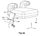
- a help device 300 differs from that of the second embodiment by its guide wall 310 and by its upper attachment means 340 to the booster seat 500.
- the aid device 300 comprises a fastening means lower identical to the means 220 and a locking stop identical to the shoulder 230 of the second embodiment.
- the inclination of the guide wall 310 relative to the connecting means may be identical to that of the second embodiment.
- a booster seat 500 has only one part, it can be obtained by molding for example.
- the aid device 300 comprises a guide wall 310 forming the guide surface 310 having a substantially rectangular shape and has an upper edge 311.
- the width of the guide surface 310 is greater than the width of the housing 7.
- the upper attachment means 340 comprises a fold 341 formed on the upper edge of the guide surface 310 which extends in a plane substantially parallel to the plane of the lower attachment means 220.
- the surface 342 of the fold 341 has a first band 343 gripping material intended to cooperate with a strip 344 of self-gripping material carried by the side wall of the seat 55 of the booster seat 500.
- the lower attachment means 220 extends only along a portion of the lower edge 312 of the guide surface 310 , a channel 313 extending along the remainder of the lower edge 312.
- the channel 313 is formed by A return of the lower edge 312.
- the channel 313 has the advantage of limiting the stroke of the bolt along the guide surface 310 but then to guide the bolt 3 to the locking / unlocking device 4.
- the user when he wishes to use the device, brings the hooking means 6 of the bolt 3 into contact with the guide surface 310 and slides it along said guide surface 310 until it enters the opening 10 and cooperates with the locking means.
- the correct trajectory of the attachment means 6 is then ensured by the width of the guide surface 310 in combination with the trough 313 , which makes it possible to ensure contact between the attachment means 6 and the locking aid device. 300.
Description
La présente invention concerne les systèmes de verrouillage/déverrouillage d'une ceinture de sécurité d'un véhicule automobile. L'invention concerne plus particulièrement les dispositifs facilitant le bouclage d'une personne assise sur un siège rehausseur.The present invention relates to the locking / unlocking systems of a seat belt of a motor vehicle. The invention relates more particularly to devices facilitating the looping of a person sitting on a booster seat.
On entend par bouclage, l'action de verrouiller la partie d'accrochage du pêne associé à une ceinture de sécurité par les moyens de verrouillage d'un dispositif de verrouillage/déverrouillage.Loop means the action of locking the hooking portion of the bolt associated with a seat belt by the locking means of a locking / unlocking device.
On entend par siège rehausseur, les sièges permettant de surélever le niveau de l'assise. Les sièges rehausseurs sont utilisés pour les personnes de petite taille. Généralement, ils sont posés sur l'assise d'un siège de véhicule. Ces sièges rehausseurs ne comportant pas de système de retenue intégré, de fait ils utilisent la ceinture de sécurité et le système de verrouillage/ déverrouillage associé au siège sur lequel ils sont posés. Pour utiliser ces sièges rehausseurs, il faut dans un premier temps poser le siège rehausseur sur l'assise du siège, puis dans un deuxième temps que la personne s'assoie sur le siège et enfin dans un dernier temps effectuer le bouclage.Booster seat means the seats to raise the level of the seat. Booster seats are used for small people. Generally, they are placed on the seat of a vehicle seat. These booster seats have no integrated restraint system, they use the seat belt and the locking / unlocking system associated with the seat on which they are placed. To use these booster seats, it is first necessary to install the booster seat on the seat cushion, then in a second time that the person sits on the seat and finally in a final time looping.
Les systèmes classiques obligent la personne assise sur son siège rehausseur à se boucler elle-même ce qui dans le cas d'un enfant est difficile compte tenu de sa position surélevée et de la longueur de ses bras. Dans le cas d'un enfant, le bouclage est effectué par un adulte qui doit se pencher par-dessus l'enfant à attacher pour effectuer le bouclage.Conventional systems require the person sitting on their booster seat to buckle themselves which in the case of a child is difficult given its raised position and the length of his arms. In the case of a child, the looping is done by an adult who has to lean over the child to be tied to make the loop.
Au vu dé ce qui précède, un objectif de l'invention est de fournir un dispositif permettant un bouclage simple et rapide quelle que soit la personne qui effectue le bouclage.In view of the foregoing, an object of the invention is to provide a device for a quick and easy loopback regardless of the person making the loop.
De plus, un autre avantage de l'invention est de s'adapter à tout type de boucle sans modification de la boucle et sans diminuer les performances du système de bouclage. En d'autres termes, le dispositif selon l'invention est capable de se fixer sur n'importe quels types de boucle sans altérer les caractéristiques de retenue du système de bouclage.In addition, another advantage of the invention is to adapt to any type of loop without modifying the loop and without reducing the performance of the loopback system. In other words, the device according to the invention is able to attach to any type of loop without altering the retaining characteristics of the loopback system.
Un objectif de l'invention est de pouvoir mettre en place et de pouvoir retirer facilement le dispositif du siège rehausseur et du système de verrouillage/déverrouillage.An object of the invention is to be able to set up and to be able to easily remove the device from the booster seat and the locking / unlocking system.
Un autre objectif est d'avoir un seul et même dispositif qui permette d'effectuer l'aide au bouclage à gauche ou à droite du siège sans qu'il soit nécessaire de modifier l'environnement existant.Another objective is to have a single device that allows to perform the loopback aid to the left or right of the seat without the need to change the existing environment.
Pour y parvenir, l'invention propose un dispositif d'aide au verrouillage d'un pêne de ceinture de sécurité dans un système de verrouillage/déverrouillage, pour un siège rehausseur de véhicule automobile.To achieve this, the invention proposes a device for assisting in the locking of a safety belt bolt in a locking / unlocking system, for a booster seat for a motor vehicle.
Selon une caractéristique générale de ce dispositif, il comporte une surface de guidage dont un bord supérieur est destiné à être disposé en regard d'une paroi latérale d'une assise du siège rehausseur et dont un bord inférieur est destiné à être disposé à proximité du système de verrouillage/déverrouillage, de façon à permettre de guider le pêne vers le système de verrouillage/ déverrouillage.According to a general characteristic of this device, it comprises a guide surface whose upper edge is intended to be arranged facing a side wall of a seat of the booster seat and a lower edge is intended to be disposed near the seat. locking / unlocking system, so as to guide the bolt to the locking / unlocking system.
Selon d'autres caractéristiques additionnelles de l'invention :
- la surface de guidage comporte des bords latéraux en saillie, et en ce que son bord supérieur est plus long que son bord inférieur, de façon à faciliter le guidage du pêne jusqu'au boîtier,
- la surface de guidage comporte un moyen d'attache supérieur apte à coopérer avec la paroi latérale de l'assise du siège rehausseur,
- le moyen d'attache supérieur est un rebord porté par le bord supérieur de la surface de guidage et apte à coopérer avec un rebord en saillie ménagé sur une partie latérale de l'assise du siège rehausseur,
- le moyen d'attache supérieur est un moyen d'accouplement de forme cylindrique porté par le bord supérieur de la surface de guidage, apte à coopérer avec un moyen de réception de forme complémentaire porté par une partie latérale de l'assise du siège rehausseur
- le moyen d'attache supérieur est un repli porté par le bord supérieur de la surface de guidage et en ce qu'il présente une face munie d'une bande de matériau auto-agrippant apte à coopérer avec une bande complémentaire portée par une partie latérale de l'assise du siège rehausseur,
- la surface de guidage comporte au moins un moyen d'attache inférieur apte à coopérer avec le système de verrouillage,
- le moyen d'attache inférieur comporte une paroi de fond, portée par le bord inférieur de la surface de guidage, depuis laquelle s'étendent des flancs latéraux déformables élastiquement, portant chacun un retour, ledit moyen d'attache inférieur étant apte à être monté autour d'un boîtier du système de verrouillage/déverrouillage,
- la zone de jonction entre la paroi de fond et la surface de guidage, sont ménagées des moyens de blocage du déplacement vers le bas du moyen d'attache inférieur lorsqu'il est sur le boîtier,
- les moyens de blocage sont constitués par une extrémité de bords latéraux en saillie portés par la surface de guidage,
- le moyen d'attache inférieur est une paroi portée par le bord inférieur de la surface de guidage, ladite paroi comportant une bande de matériau auto-agrippant apte à coopérer avec une bande complémentaire portée par le boitier du système de verrouillage/ déverrouillage,
- le bord inférieur comporte un épaulement formant une butée de blocage du déplacement du boîtier selon une direction sensiblement verticale du moyen d'attache inférieur par rapport au boîtier,
- le moyen d'attache inférieur s'étend sur une première partie du bord inférieur de la surface de guidage et en ce qu'une deuxième partie du bord inférieur comporte une rigole de butée de fin de course et de guidage du pêne jusqu'au système de verrouillage/ déverrouillage,
- the guide surface has projecting lateral edges, and in that its upper edge is longer than its lower edge, so as to facilitate the guiding of the bolt to the housing,
- the guide surface comprises an upper attachment means adapted to cooperate with the side wall of the seat of the booster seat,
- the upper attachment means is a flange carried by the upper edge of the guide surface and adapted to cooperate with a protruding flange formed on a lateral portion of the seat of the booster seat,
- the upper attachment means is a cylindrical coupling means carried by the upper edge of the guide surface, adapted to cooperate with a complementary form receiving means carried by a side portion of the seat of the booster seat
- the upper attachment means is a fold carried by the upper edge of the guide surface and in that it has a face provided with a strip of self-gripping material adapted to cooperate with a complementary strip carried by a lateral portion the seat of the booster seat,
- the guide surface comprises at least one lower attachment means adapted to cooperate with the locking system,
- the lower attachment means comprises a bottom wall, carried by the lower edge of the guide surface, from which elastically deformable lateral flanks extend, each bearing a return, said lower attachment means being adapted to be mounted around a housing of the locking / unlocking system,
- the junction zone between the bottom wall and the guide surface is provided with means for blocking the downward movement of the lower attachment means when it is on the housing,
- the locking means consist of an end of projecting lateral edges carried by the guiding surface,
- the lower attachment means is a wall carried by the lower edge of the guide surface, said wall comprising a strip of self-gripping material capable of cooperating with a complementary strip carried by the housing of the locking / unlocking system,
- the lower edge comprises a shoulder forming a stop blocking the displacement of the housing in a substantially vertical direction of the lower attachment means relative to the housing,
- the lower fastening means extends over a first portion of the lower edge of the guide surface and in that a second portion of the lower edge comprises a limit stop and guide groove of the bolt to the system locking / unlocking,
Selon une autre caractéristique de l'invention, un siège rehausseur comportant une assise et comportant un moyen de réception apte à coopérer avec un moyen d'attache supérieur complémentaire d'un dispositif d'aide au verrouillage.According to another characteristic of the invention, a booster seat comprising a seat and comprising a receiving means adapted to cooperate with an upper attachment means complementary to a locking aid device.
Selon d'autres caractéristiques additionnelles de l'invention :
- le moyen de réception est un bord en saillie ménagé sur une partie latérale de l'assise du siège rehausseur, apte à coopérer avec le moyen d'attache supérieur du dispositif d'aide formé d'un rebord,
- le moyen de réception est une gorge portée par une plaque disposée dans une cavité ménagée dans une partie latérale d'une assise du siège rehausseur, apte à coopérer avec le moyen d'attache supérieur formé par un moyen d'accouplement cylindrique,
- the receiving means is a protruding edge formed on a lateral part of the seat of the booster seat, adapted to cooperate with the upper fastening means of the aid device formed by a flange,
- the receiving means is a groove carried by a plate disposed in a cavity formed in a lateral part of a seat of the booster seat, adapted to cooperate with the upper attachment means formed by a cylindrical coupling means,
D'autres caractéristiques et avantages de la présente invention apparaîtront à la lecture de la description suivante donnée à titre d'exemple illustratif et non limitatif et faite en référence aux figures annexées dans lesquélles :
- La
figure 1 illustre un système de verrouillage/déverrouillage d'un véhicule automobile, - La
figure 2 illustre un siège rehausseur associé à l'invention, - Les
figures 3a à 3d illustrent un premier mode de réalisation selon l'invention, - Les
figures 4a à 4f illustrent un deuxième mode de réalisation selon l'invention, - Les
figures 5a à 5d illustrent un mode de réalisation ne faisant pas partie de l'invention,
- The
figure 1 illustrates a locking / unlocking system of a motor vehicle, - The
figure 2 illustrates a booster seat associated with the invention, - The
Figures 3a to 3d illustrate a first embodiment according to the invention, - The
Figures 4a to 4f illustrate a second embodiment according to the invention, - The
Figures 5a to 5d illustrate an embodiment not forming part of the invention,
Les moyens analogues dans les différents modes de réalisation comportent la même numérotation.The analogous means in the different embodiments have the same numbering.
En référence à la
Comme illustré à la
Le pêne 3 comporte un support 5 monté coulissant sur la sangle 2, et un moyen d'accrochage 6 capable de coopérer avec les moyens de verrouillage/déverrouillage du dispositif de verrouillage/déverrouillage 4. Le moyen d'accrochage 6 peut présenter la forme d'une plaque percée d'un trou.The
Le dispositif de verrouillage/déverrouillage 4 du pêne comprend des moyens de verrouillage (non représentés) disposés à l'intérieur d'un boitier (ou carter) 7, un bouton 8 actionnant le déverrouillage du dispositif 4 et des moyens de rattachement 9 à un élément fixe du véhicule, par exemple le siège ou le plancher véhicule. Le boitier 7 comprend, notamment, une face 7A destinée à être en vis-à-vis de l'utilisateur d'un siège automobile associé au dispositif de verrouillage/déverrouillage 4. The locking / unlocking
Un dispositif de verrouillage/déverrouillage 4 classique comprend, également, une ouverture supérieure 10, située dans une partie supérieure 11 du boitier 7, et permettant le passage du pêne 3 vers et/ou depuis sa position de verrouillage.A conventional locking / unlocking
En référence à la
En référence à la
Un dispositif d'aide au verrouillage 100, tel que représenté aux
La paroi 110 comporte un plan de symétrie P, ce plan de symétrie P est orthogonal à la paroi 110. La paroi 110 comporte, également, un bord supérieur 111 s'étendant à proximité de l'assise 55 du siège rehausseur 51 et un bord inférieur 112 s'étendant à proximité du moyen de verrouillage/déverrouillage 4.The
Elle présente une forme générale trapézoïdale, le bord supérieur 111 étant plus long que le bord inférieur 112, de façon à former un entonnoir.It has a generally trapezoidal shape, the
La paroi 110 comporte des rebords en saille 113 qui s'étendent sensiblement perpendiculairement par rapport à la surface de la paroi 110.The
La paroi 110 est inclinée par rapport au plan du boîtier 7, ceci présente l'avantage de pouvoir faciliter l'introduction du moyen d'accrochage 6 du pêne 3 dans l'ouverture 10. En d'autres termes, l'utilisateur n'a pas la nécessité de modifier la préhension du pêne 3 en vue d'un verrouillage.The
La combinaison de la forme trapézoïdale de la paroi 110 et des rebords en saillie 113 forme un entonnoir ou une goulotte de guidage et présente l'avantage de faciliter le guidage du pêne 3. The combination of the trapezoidal shape of the
De plus, comme la paroi 110 est symétrique la paroi par rapport au plan P, cette caractéristique présente l'avantage de permettre l'adaptation du dispositif d'aide au verrouillage 100 pour un bouclage à droite ou à gaucheIn addition, since the
Par ailleurs, la paroi 110 comporte un moyen d'attache inférieur 120 destiné à coopérer avec le dispositif de verrouillage/déverrouillage 4 et un moyen d'attache supérieur 140 destiné à coopérer avec l'assise 55 du siège rehausseur 51. Furthermore, the
Le moyen d'attache inférieur 120 apte à coopérer avec le boitier 7 du dispositif de verrouillage/déverrouillage 4, est porté par le bord inférieur 112 de la paroi 110. Tel que représenté à la
Le moyen d'attaché inférieur 120 comporte des moyens de blocage 130 destiné à limiter le déplacement du dispositif d'aide au verrouillage 100 vers le bas lorsqu'il est inséré sur le boîtier 7. Ce moyen de blocage 130 est formé par des butées localisées au niveau du bord inférieur 112 de la paroi 110, c'est-à-dire dans une zone supérieure de la paroi de fond 121 et viennent en appui contre les extrémités latérales des bords extérieurs de l'ouverture supérieure 10 du boitier 7. The lower attachment means 120 includes locking means 130 for limiting the movement of the lock assist
Les moyens de blocage 130 peuvent être formés par une extrémité inférieure des rebords en saillie 113 venant en butée contre les extrémités des bords de la partie supérieure 11 du boîtier 7. The locking means 130 may be formed by a lower end of the protruding
Le dispositif d'aide au verrouillage 100 comporte, également, un moyen d'attache supérieur 140 destiné à coopérer avec le siège rehausseur 51. Le moyen d'attache supérieur 140 est formé d'un rebord 141 relié au bord supérieur 111 par une zone de jonction 142. Le rebord 141 est, comme représenté aux
L'utilisateur, lorsqu'il souhaite boucler la ceinture, amène le moyen d'accrochage 6 du pêne en contact avec la paroi 110 et le fait glisser le long de ladite paroi 110 jusqu'à ce qu'il pénètre dans l'ouverture 10 du boîtier 7 et coopère avec les moyens de verrouillage. La trajectoire correcte du moyen d'accrochage 6 est alors assurée par la forme en entonnoir de la paroi 110 et par les rebords en saillie 113, qui empêchent toute déviation du moyen d'accrochage 6. The user, when he wants to buckle the belt, brings the
Selon un autre mode de réalisation présenté aux
Le dispositif d'aide au verrouillage 200 comporte une paroi de guidage 110 analogue à celle du dispositif 100 selon le premier mode de réalisation. L'inclinaison de la paroi 110 par rapport à un moyen de liaison avec le boitier 7, peut être identique à celles du premier mode de réalisation présenté.The lock-up
Selon le mode de réalisation présenté aux
Ainsi, la première bande 222 est placée au niveau de la face 221 du moyen d'attache inférieur 220 du dispositif de verrouillage/déverrouillage. La deuxième bande 223 est placée sur la face 7A du boitier 7. Thus, the
Selon le mode de réalisation présenté, le dispositif d'aide au verrouillage 200 comporte un épaulement 230. Ledit épaulement 230 est défini par une nervure située entre le moyen d'attache inférieur 220 et la paroi 110. L'épaulement 230 s'étend le long bord inférieur 112. En d'autres termes l'épaulement 230 est destiné à s'étendre le long du bord de l'ouverture 10 lorsque le dispositif d'aide au verrouillage 200 est monté sur le boitier 7, de façon à former un moyen de blocage permettant de limiter le déplacement vers le bas du moyen d'attache inférieur 220 par rapport au boîtier 7. According to the embodiment shown, the lock-up
Le dispositif d'aide au verrouillage 200 comprend, dans ce mode de réalisation, un moyen d'attache supérieur 240 apte à coopérer avec un moyen complémentaire de l'assise du siège rehausseur 51. The locking
Le moyen d'attache supérieur 240 du dispositif d'aide au verrouillage 200 est porté par le bord supérieur 111 de la paroi 110 et présente une forme cylindrique.The upper attachment means 240 of the
Tel que représenté aux
La cavité 241 peut être située à cheval entre la partie supérieure 53 et la partie inférieur 52 du siège rehausseur 51. The
Une plaque 242, comme représentée aux
L'élément de réception 245 comporte une gorge 246 dont la forme est complémentaire de celle du moyen d'attache supérieur 240. Cette gorge 246 est définie par deux parois 247 capables de se déformer élastiquement.The receiving
Le couplage du moyen d'attache supérieur 240 et de l'élément de réception 245 autorise cependant une certaine rotation du dispositif.The coupling of the upper attachment means 240 and the receiving
Le siège rehausseur est livré déjà pré-équipé de la plaque 242. Comme représenté aux
Pour fixer le moyen d'attache supérieur 240, il suffit de le faire passer au travers de l'ouverture 243, puis de l'insérer dans la gorge 246 par une action de pression. Sous l'effet de la pression exercée, les parois 247 vont se déformer élastiquement et s'ouvrir pour laisser passer le moyen d'attache supérieur 240, La pression transmise au moyen d'accouplement 230 exerce sur les parois 247, définissant la gorge 246, une déformation élastique sur chacun des parois 247. Une fois le moyen d'attache supérieur 240 complètement inséré dans la gorge 246, les parois 247 vont se refermer sur ledit moyen d'attache supérieur 240. L'effort des parois 247 sur le moyen d'attache supérieur 240 permet de maintenir le moyen d'attache supérieur 240 dans la gorge 246 tout en permettant la rotation du moyen d'attache supérieur 230 autour de son axe.To fix the upper attachment means 240 , it is sufficient to pass through the
Le fait que la plaque 242 ait un jeu présente, en outre, l'avantage d'assurer un assemblage sans contrainte du moyen d'attache inférieur 220 avec le boitier 7. The fact that the
Selon une variante non représentée, le moyen d'attache supérieur 240 dans la gorge peut être monté axialement, selon l'axe i, dans la gorge 246. Ce montage permet de rendre le dispositif d'aide au verrouillage 200 solidaire du siège rehausseur 51. According to a variant not shown, the upper attachment means 240 in the groove can be mounted axially, along the axis i, in the
Selon un mode de réalisation, non représenté, le siège rehausseur 51 peut comporter deux cavités opposées sur chacune des parois latérales de son assise. Le siège rehausseur 51 est alors équipé dans ce cas de deux plaques, une plaque 242 par cavité, permettant de coupler le siège rehausseur 51 avec le dispositif d'aide au verrouillage 200 pour un bouclage à gauche ou à droite.According to one embodiment, not shown, the
L'utilisateur, lorsqu'il souhaite boucler la ceinture, amène le moyen d'accrochage 6 du pêne en contact avec la paroi 110 et le fait glisser le long de ladite paroi 110 jusqu'à ce qu'il pénètre dans l'ouverture 10 du boîtier 7 et coopère avec les moyens de verrouillage. La trajectoire correcte du moyen d'accrochage 6 est alors assurée par la forme en entonnoir de la paroi 110 et par les rebords 143, qui empêchent toute déviation du moyen d'accrochage 6.The user, when he wants to buckle the belt, brings the
Selon un mode de réalisation ne faisant pas partie de l'invention présenté à la
De plus, ici, l'inclinaison de la paroi de guidage 310 par rapport au moyen de liaison peut être identique à celle du deuxième mode de réalisation.In addition, here, the inclination of the
Alternativement, selon le mode de réalisation introduit aux
Le dispositif d'aide 300 comporte une paroi de guidage 310 formant la surface de guidage 310 présentant une forme sensiblement rectangulaire et comporte un bord supérieur 311. La largeur de la surface de guidage 310 est supérieure à la largeur du boitier 7. The
Dans le dispositif d'aide 300, selon ce troisième mode de réalisation présenté aux
Le moyen d'attache inférieur 220 s'étend, seulement, le long d'une portion du bord inférieur 312 de la surface de guidage 310, une rigole 313 s'étendant le long du reste du bord inférieur 312 La rigole 313 est formée par un retour du bord inférieur 312. La rigole 313 présente l'avantage de limiter la course du pêne le long de la surface de guidage 310 mais ensuite de guider le pêne 3 jusqu'au dispositif de verrouillage/déverrouillage 4. The lower attachment means 220 extends only along a portion of the
Ainsi, l'utilisateur, lorsqu'il souhaite utiliser le dispositif, amène le moyen d'accrochage 6 du pêne 3 en contact avec la surface de guidage 310 et le fait glisser le long de ladite surface de guidage 310 jusqu'à ce qu'il pénètre dans l'ouverture 10 et coopère avec les moyens de verrouillage. La trajectoire correcte du moyen d'accrochage 6 est alors assurée par la largeur de la surface de guidage 310 en combinaison avec la rigole 313, qui permet d'assurer le contact entre le moyen d'accrochage 6 et le dispositif d'aide au verrouillage 300. Thus, the user, when he wishes to use the device, brings the hooking
Claims (13)
- Device for assisting locking of a tongue of a safety belt (3) in a locking/unlocking system (4) for a motor vehicle booster seat (51), the device including a guide surface (110), an upper edge (111) of which is intended to be disposed facing a lateral wall of a base (55) of the booster seat (51) and a lower edge (112) of which is intended to be disposed in the vicinity of the locking/unlocking system (4) so as to make it possible to guide the tongue (3) toward the locking/unlocking system (4), characterized in that the guide surface (110) includes projecting lateral edges (113) and in that the guide surface (110) has a trapezoidal general shape, the upper edge (111) being longer than the lower edge (112), so as to form a funnel and so as to facilitate guiding the tongue (3) to the casing (7) of the locking/unlocking system (4).
- Device according to Claim 1, characterized in that the guide surface (110) includes upper attachment means (140, 240) adapted to cooperate with the lateral wall of the base (55) of the booster seat (51, 500).
- Device according to Claim 2, characterized in that the upper attachment means consist of a rim (141) carried by the upper edge (111) of the guide surface (110) and adapted to cooperate with a projecting rim (143) on a lateral part of the base of the booster seat (51).
- Device according to Claim 2, characterized in that the upper attachment means (240) consist of cylindrical coupling means carried by the upper edge (111) of the guide surface (110) adapted to cooperate with receiving means (245) of complementary shape carried by a lateral part of the base of the booster seat (51).
- Device according to any one of Claims 1 to 5, characterized in that the guide surface (110) includes lower attachment means (120, 220) adapted to cooperate with the locking system (4).
- Device according to Claim 5, characterized in that the lower attachment means (120) include a bottom wall (121) carried by the lower edge (111) of the guide surface (110) from which extend elastically deformable lateral flanks (122) each carrying a return (123), said lower attachment means (120) being adapted to be mounted around a casing (7) of the locking/unlocking system (4).
- Device according to Claim 6, characterized in that means (130) are provided in the joining area between the bottom wall (121) and the guide surface (110) for immobilizing the lower attachment means (120) against downward movement when it is on the casing (7).
- Device according to Claim 7, characterized in that the immobilizing means (130) consist of an extremity of projecting lateral edges (113) carried by the guide surface (110).
- Device according to Claim 6, characterized in that the lower attachment means (220) consist of a wall carried by the lower edge (112, 312) of the guide surface (110), said wall including a strip of self-grip material (222) adapted to cooperate with a complementary strip (223) carried by the casing (7) of the locking/unlocking system (4).
- Device according to Claim 9, characterized in that the lower edge (112) includes a shoulder (230) forming an abutment for immobilizing the casing (7) against movement in a substantially vertical direction of the lower attachment means (220) relative to the casing (7).
- Booster seat (51, 500) including a base (55) and including receiving means adapted to cooperate with complementary upper attachment means (140, 240) of a device (100, 200) according to any one of Claims 1 to 10.
- Booster seat (51) according to Claim 11, characterized in that the receiving means consist of a projecting edge (143) provided on a lateral part of the base (55) of the booster seat (51) adapted to cooperate with the upper attachment means of the assistance device (100) formed by a rim (141).
- Booster seat (51) according to Claim 11, characterized in that the receiving means consist of a groove (246) carried by a plate (242) disposed in a cavity (241) provided in a lateral part of a base (55) of the booster seat (51) adapted to cooperate with the upper attachment means (240) formed by cylindrical coupling means.
Applications Claiming Priority (2)
| Application Number | Priority Date | Filing Date | Title |
|---|---|---|---|
| FR1061327A FR2969977B1 (en) | 2010-12-29 | 2010-12-29 | DEVICE FOR ASSISTING THE GUIDE OF A SEAT BELT SEAT FOR BOOSTER SEAT |
| PCT/EP2011/070207 WO2012089401A1 (en) | 2010-12-29 | 2011-11-16 | Device for assisting in the guiding of a seat belt latch for a booster seat |
Publications (2)
| Publication Number | Publication Date |
|---|---|
| EP2658741A1 EP2658741A1 (en) | 2013-11-06 |
| EP2658741B1 true EP2658741B1 (en) | 2016-07-20 |
Family
ID=44351843
Family Applications (1)
| Application Number | Title | Priority Date | Filing Date |
|---|---|---|---|
| EP11782160.3A Not-in-force EP2658741B1 (en) | 2010-12-29 | 2011-11-16 | Device helping guiding of a safety belt tongue for child booster seat |
Country Status (3)
| Country | Link |
|---|---|
| EP (1) | EP2658741B1 (en) |
| FR (1) | FR2969977B1 (en) |
| WO (1) | WO2012089401A1 (en) |
Families Citing this family (5)
| Publication number | Priority date | Publication date | Assignee | Title |
|---|---|---|---|---|
| CN106114305A (en) * | 2016-06-18 | 2016-11-16 | 金余和 | basket type safety seat with safety belt assembly |
| CN106043002A (en) * | 2016-06-18 | 2016-10-26 | 金余和 | Infant safety seat with safety belt assembly |
| US10631596B2 (en) * | 2016-08-19 | 2020-04-28 | Eunice Hanson | Guide wall attachment device for a seat belt receiver |
| CN108657033B (en) * | 2018-05-17 | 2024-03-01 | 麦克英孚(宁波)婴童用品有限公司 | Safety seat with adjustable headrest |
| CN114475376B (en) * | 2022-02-21 | 2023-04-07 | 欧颂德婴童用品(湖北)有限公司 | Quick unlocking device and unlocking method for upper pull belt hook |
Family Cites Families (3)
| Publication number | Priority date | Publication date | Assignee | Title |
|---|---|---|---|---|
| JP2002079909A (en) * | 2000-09-09 | 2002-03-19 | Motoi Oda | Auxiliary tool for seat belt buckle |
| DE10314042B4 (en) * | 2003-03-28 | 2005-11-03 | Darren Horspool | Holder for safety belt buckle |
| US7648209B2 (en) * | 2006-03-01 | 2010-01-19 | Elisabeth Weinstein | Seat belt buckle positioning system |
-
2010
- 2010-12-29 FR FR1061327A patent/FR2969977B1/en not_active Expired - Fee Related
-
2011
- 2011-11-16 EP EP11782160.3A patent/EP2658741B1/en not_active Not-in-force
- 2011-11-16 WO PCT/EP2011/070207 patent/WO2012089401A1/en active Application Filing
Also Published As
| Publication number | Publication date |
|---|---|
| EP2658741A1 (en) | 2013-11-06 |
| WO2012089401A1 (en) | 2012-07-05 |
| FR2969977B1 (en) | 2012-12-21 |
| FR2969977A1 (en) | 2012-07-06 |
Similar Documents
| Publication | Publication Date | Title |
|---|---|---|
| EP2658741B1 (en) | Device helping guiding of a safety belt tongue for child booster seat | |
| EP3041652B1 (en) | Retaining device having hooks | |
| FR2643597A1 (en) | CHILD SEAT RESTRAINT ASSEMBLY AND BASE OF SUCH AN ASSEMBLY | |
| EP1787878B1 (en) | Mounting device in particular for a push rod of the power brake to the brake pedal of a motor vehicle | |
| FR2975643A1 (en) | Seat e.g. individual seat, for car, has protective cover mounted movably on anchoring rod between closed position, in which cover is in continuity with backrest and prevents access to rod, and open position to release access to rod | |
| EP2445748B1 (en) | Device for rigidly connecting a seat portion to a vehicle floor | |
| FR2868023A1 (en) | VEHICLE SEAT BACKREST SUITABLE FOR PERMITTING THE FIXING OF A CHILD SEAT AND VEHICLE SEAT COMPRISING SUCH A DOSSIER | |
| FR3014043A1 (en) | VEHICLE SEAT EQUIPPED WITH AT LEAST ONE PASSENGER ACCESS TO A CAR SEAT ANCHOR WIRE AND CORRESPONDING VEHICLE | |
| EP1747114B1 (en) | Device for plugging a blocking element | |
| EP2384925B1 (en) | Seat backrest body made of blow-molded plastic, comprising an anchoring device for secure attachment of a child safety seat | |
| WO2012089402A1 (en) | Seat belt locking buckle comprising a protective flap, and protective flap for such a buckle | |
| FR2810929A1 (en) | Vehicle seat mounted on support integral with vehicle has hooking part on second end which engages complementary part on support when vehicle undergoes longitudinal shock | |
| EP2525688A1 (en) | Assembly of a molded object that comprises a plurality of overmolded hook elements and further comprises a covering | |
| FR3005015A1 (en) | DEVICE FOR ANCHORING SECURITY BELT BUCKLES | |
| EP0225248B1 (en) | Safety belt buckle, in particular for a motor vehicle | |
| EP3386795B1 (en) | Arrangement for mounting an armrest on a vehicle door | |
| FR2964349A1 (en) | Device for fixing cover e.g. textile cover, at seat in railway vehicle, has female fixing unit comprising groove that cooperates with interval of flexible cord between stop elements to fix fixing device at frame | |
| EP1776259A1 (en) | Retaining means arrangement inside a motor vehicle | |
| EP1663697A2 (en) | Device for locking a removable car seat | |
| WO2022018367A1 (en) | Unit with a movable front for attachment of a portable electronic device in a motor vehicle | |
| FR3017583A1 (en) | DEVICE FOR SEAT BELT | |
| FR3102106A1 (en) | DEVICE FOR FIXING A BENCH SEAT ON A MOTOR VEHICLE FRAME | |
| FR3014783A1 (en) | DECORATIVE PLATE FOR FIXING ON A VEHICLE SEAT | |
| FR2941904A1 (en) | Safety device for three point safety belt of child in motor vehicle, has movable safety mobile shutter released manually from its occultation position by exerting determined force on shutter in order to reach pusher | |
| FR3014780A1 (en) | AUTOMOTIVE SEAT POST, AUTOMOTIVE SEAT ELEMENT AND VEHICLE EQUIPPED WITH A SEAT COMPRISING SUCH AN ELEMENT |
Legal Events
| Date | Code | Title | Description |
|---|---|---|---|
| PUAI | Public reference made under article 153(3) epc to a published international application that has entered the european phase |
Free format text: ORIGINAL CODE: 0009012 |
|
| 17P | Request for examination filed |
Effective date: 20130607 |
|
| AK | Designated contracting states |
Kind code of ref document: A1 Designated state(s): AL AT BE BG CH CY CZ DE DK EE ES FI FR GB GR HR HU IE IS IT LI LT LU LV MC MK MT NL NO PL PT RO RS SE SI SK SM TR |
|
| DAX | Request for extension of the european patent (deleted) | ||
| 17Q | First examination report despatched |
Effective date: 20141114 |
|
| GRAP | Despatch of communication of intention to grant a patent |
Free format text: ORIGINAL CODE: EPIDOSNIGR1 |
|
| INTG | Intention to grant announced |
Effective date: 20160202 |
|
| GRAS | Grant fee paid |
Free format text: ORIGINAL CODE: EPIDOSNIGR3 |
|
| GRAA | (expected) grant |
Free format text: ORIGINAL CODE: 0009210 |
|
| AK | Designated contracting states |
Kind code of ref document: B1 Designated state(s): AL AT BE BG CH CY CZ DE DK EE ES FI FR GB GR HR HU IE IS IT LI LT LU LV MC MK MT NL NO PL PT RO RS SE SI SK SM TR |
|
| REG | Reference to a national code |
Ref country code: GB Ref legal event code: FG4D Free format text: NOT ENGLISH |
|
| REG | Reference to a national code |
Ref country code: CH Ref legal event code: EP |
|
| REG | Reference to a national code |
Ref country code: IE Ref legal event code: FG4D Free format text: LANGUAGE OF EP DOCUMENT: FRENCH |
|
| REG | Reference to a national code |
Ref country code: AT Ref legal event code: REF Ref document number: 813776 Country of ref document: AT Kind code of ref document: T Effective date: 20160815 |
|
| REG | Reference to a national code |
Ref country code: DE Ref legal event code: R096 Ref document number: 602011028396 Country of ref document: DE |
|
| REG | Reference to a national code |
Ref country code: LT Ref legal event code: MG4D |
|
| REG | Reference to a national code |
Ref country code: FR Ref legal event code: PLFP Year of fee payment: 6 |
|
| REG | Reference to a national code |
Ref country code: NL Ref legal event code: MP Effective date: 20160720 |
|
| REG | Reference to a national code |
Ref country code: AT Ref legal event code: MK05 Ref document number: 813776 Country of ref document: AT Kind code of ref document: T Effective date: 20160720 |
|
| PG25 | Lapsed in a contracting state [announced via postgrant information from national office to epo] |
Ref country code: RS Free format text: LAPSE BECAUSE OF FAILURE TO SUBMIT A TRANSLATION OF THE DESCRIPTION OR TO PAY THE FEE WITHIN THE PRESCRIBED TIME-LIMIT Effective date: 20160720 Ref country code: FI Free format text: LAPSE BECAUSE OF FAILURE TO SUBMIT A TRANSLATION OF THE DESCRIPTION OR TO PAY THE FEE WITHIN THE PRESCRIBED TIME-LIMIT Effective date: 20160720 Ref country code: NL Free format text: LAPSE BECAUSE OF FAILURE TO SUBMIT A TRANSLATION OF THE DESCRIPTION OR TO PAY THE FEE WITHIN THE PRESCRIBED TIME-LIMIT Effective date: 20160720 Ref country code: IS Free format text: LAPSE BECAUSE OF FAILURE TO SUBMIT A TRANSLATION OF THE DESCRIPTION OR TO PAY THE FEE WITHIN THE PRESCRIBED TIME-LIMIT Effective date: 20161120 Ref country code: LT Free format text: LAPSE BECAUSE OF FAILURE TO SUBMIT A TRANSLATION OF THE DESCRIPTION OR TO PAY THE FEE WITHIN THE PRESCRIBED TIME-LIMIT Effective date: 20160720 Ref country code: IT Free format text: LAPSE BECAUSE OF FAILURE TO SUBMIT A TRANSLATION OF THE DESCRIPTION OR TO PAY THE FEE WITHIN THE PRESCRIBED TIME-LIMIT Effective date: 20160720 Ref country code: NO Free format text: LAPSE BECAUSE OF FAILURE TO SUBMIT A TRANSLATION OF THE DESCRIPTION OR TO PAY THE FEE WITHIN THE PRESCRIBED TIME-LIMIT Effective date: 20161020 Ref country code: HR Free format text: LAPSE BECAUSE OF FAILURE TO SUBMIT A TRANSLATION OF THE DESCRIPTION OR TO PAY THE FEE WITHIN THE PRESCRIBED TIME-LIMIT Effective date: 20160720 |
|
| PG25 | Lapsed in a contracting state [announced via postgrant information from national office to epo] |
Ref country code: ES Free format text: LAPSE BECAUSE OF FAILURE TO SUBMIT A TRANSLATION OF THE DESCRIPTION OR TO PAY THE FEE WITHIN THE PRESCRIBED TIME-LIMIT Effective date: 20160720 Ref country code: PL Free format text: LAPSE BECAUSE OF FAILURE TO SUBMIT A TRANSLATION OF THE DESCRIPTION OR TO PAY THE FEE WITHIN THE PRESCRIBED TIME-LIMIT Effective date: 20160720 Ref country code: LV Free format text: LAPSE BECAUSE OF FAILURE TO SUBMIT A TRANSLATION OF THE DESCRIPTION OR TO PAY THE FEE WITHIN THE PRESCRIBED TIME-LIMIT Effective date: 20160720 Ref country code: AT Free format text: LAPSE BECAUSE OF FAILURE TO SUBMIT A TRANSLATION OF THE DESCRIPTION OR TO PAY THE FEE WITHIN THE PRESCRIBED TIME-LIMIT Effective date: 20160720 Ref country code: BE Free format text: LAPSE BECAUSE OF NON-PAYMENT OF DUE FEES Effective date: 20161130 Ref country code: SE Free format text: LAPSE BECAUSE OF FAILURE TO SUBMIT A TRANSLATION OF THE DESCRIPTION OR TO PAY THE FEE WITHIN THE PRESCRIBED TIME-LIMIT Effective date: 20160720 Ref country code: GR Free format text: LAPSE BECAUSE OF FAILURE TO SUBMIT A TRANSLATION OF THE DESCRIPTION OR TO PAY THE FEE WITHIN THE PRESCRIBED TIME-LIMIT Effective date: 20161021 Ref country code: PT Free format text: LAPSE BECAUSE OF FAILURE TO SUBMIT A TRANSLATION OF THE DESCRIPTION OR TO PAY THE FEE WITHIN THE PRESCRIBED TIME-LIMIT Effective date: 20161121 |
|
| REG | Reference to a national code |
Ref country code: DE Ref legal event code: R097 Ref document number: 602011028396 Country of ref document: DE |
|
| PG25 | Lapsed in a contracting state [announced via postgrant information from national office to epo] |
Ref country code: EE Free format text: LAPSE BECAUSE OF FAILURE TO SUBMIT A TRANSLATION OF THE DESCRIPTION OR TO PAY THE FEE WITHIN THE PRESCRIBED TIME-LIMIT Effective date: 20160720 Ref country code: RO Free format text: LAPSE BECAUSE OF FAILURE TO SUBMIT A TRANSLATION OF THE DESCRIPTION OR TO PAY THE FEE WITHIN THE PRESCRIBED TIME-LIMIT Effective date: 20160720 |
|
| PLBE | No opposition filed within time limit |
Free format text: ORIGINAL CODE: 0009261 |
|
| STAA | Information on the status of an ep patent application or granted ep patent |
Free format text: STATUS: NO OPPOSITION FILED WITHIN TIME LIMIT |
|
| PG25 | Lapsed in a contracting state [announced via postgrant information from national office to epo] |
Ref country code: SM Free format text: LAPSE BECAUSE OF FAILURE TO SUBMIT A TRANSLATION OF THE DESCRIPTION OR TO PAY THE FEE WITHIN THE PRESCRIBED TIME-LIMIT Effective date: 20160720 Ref country code: BG Free format text: LAPSE BECAUSE OF FAILURE TO SUBMIT A TRANSLATION OF THE DESCRIPTION OR TO PAY THE FEE WITHIN THE PRESCRIBED TIME-LIMIT Effective date: 20161020 Ref country code: CZ Free format text: LAPSE BECAUSE OF FAILURE TO SUBMIT A TRANSLATION OF THE DESCRIPTION OR TO PAY THE FEE WITHIN THE PRESCRIBED TIME-LIMIT Effective date: 20160720 Ref country code: SK Free format text: LAPSE BECAUSE OF FAILURE TO SUBMIT A TRANSLATION OF THE DESCRIPTION OR TO PAY THE FEE WITHIN THE PRESCRIBED TIME-LIMIT Effective date: 20160720 Ref country code: DK Free format text: LAPSE BECAUSE OF FAILURE TO SUBMIT A TRANSLATION OF THE DESCRIPTION OR TO PAY THE FEE WITHIN THE PRESCRIBED TIME-LIMIT Effective date: 20160720 |
|
| 26N | No opposition filed |
Effective date: 20170421 |
|
| REG | Reference to a national code |
Ref country code: CH Ref legal event code: PL |
|
| PG25 | Lapsed in a contracting state [announced via postgrant information from national office to epo] |
Ref country code: CH Free format text: LAPSE BECAUSE OF NON-PAYMENT OF DUE FEES Effective date: 20161130 Ref country code: LI Free format text: LAPSE BECAUSE OF NON-PAYMENT OF DUE FEES Effective date: 20161130 |
|
| REG | Reference to a national code |
Ref country code: IE Ref legal event code: MM4A |
|
| PG25 | Lapsed in a contracting state [announced via postgrant information from national office to epo] |
Ref country code: SI Free format text: LAPSE BECAUSE OF FAILURE TO SUBMIT A TRANSLATION OF THE DESCRIPTION OR TO PAY THE FEE WITHIN THE PRESCRIBED TIME-LIMIT Effective date: 20160720 |
|
| PG25 | Lapsed in a contracting state [announced via postgrant information from national office to epo] |
Ref country code: LU Free format text: LAPSE BECAUSE OF NON-PAYMENT OF DUE FEES Effective date: 20161130 |
|
| REG | Reference to a national code |
Ref country code: FR Ref legal event code: PLFP Year of fee payment: 7 |
|
| PG25 | Lapsed in a contracting state [announced via postgrant information from national office to epo] |
Ref country code: IE Free format text: LAPSE BECAUSE OF NON-PAYMENT OF DUE FEES Effective date: 20161116 |
|
| REG | Reference to a national code |
Ref country code: BE Ref legal event code: MM Effective date: 20161130 |
|
| PG25 | Lapsed in a contracting state [announced via postgrant information from national office to epo] |
Ref country code: CY Free format text: LAPSE BECAUSE OF FAILURE TO SUBMIT A TRANSLATION OF THE DESCRIPTION OR TO PAY THE FEE WITHIN THE PRESCRIBED TIME-LIMIT Effective date: 20160720 Ref country code: HU Free format text: LAPSE BECAUSE OF FAILURE TO SUBMIT A TRANSLATION OF THE DESCRIPTION OR TO PAY THE FEE WITHIN THE PRESCRIBED TIME-LIMIT; INVALID AB INITIO Effective date: 20111116 |
|
| PG25 | Lapsed in a contracting state [announced via postgrant information from national office to epo] |
Ref country code: MC Free format text: LAPSE BECAUSE OF FAILURE TO SUBMIT A TRANSLATION OF THE DESCRIPTION OR TO PAY THE FEE WITHIN THE PRESCRIBED TIME-LIMIT Effective date: 20160720 Ref country code: MK Free format text: LAPSE BECAUSE OF FAILURE TO SUBMIT A TRANSLATION OF THE DESCRIPTION OR TO PAY THE FEE WITHIN THE PRESCRIBED TIME-LIMIT Effective date: 20160720 |
|
| PG25 | Lapsed in a contracting state [announced via postgrant information from national office to epo] |
Ref country code: MT Free format text: LAPSE BECAUSE OF FAILURE TO SUBMIT A TRANSLATION OF THE DESCRIPTION OR TO PAY THE FEE WITHIN THE PRESCRIBED TIME-LIMIT Effective date: 20160720 |
|
| PG25 | Lapsed in a contracting state [announced via postgrant information from national office to epo] |
Ref country code: AL Free format text: LAPSE BECAUSE OF FAILURE TO SUBMIT A TRANSLATION OF THE DESCRIPTION OR TO PAY THE FEE WITHIN THE PRESCRIBED TIME-LIMIT Effective date: 20160720 Ref country code: TR Free format text: LAPSE BECAUSE OF FAILURE TO SUBMIT A TRANSLATION OF THE DESCRIPTION OR TO PAY THE FEE WITHIN THE PRESCRIBED TIME-LIMIT Effective date: 20160720 |
|
| PGFP | Annual fee paid to national office [announced via postgrant information from national office to epo] |
Ref country code: FR Payment date: 20211122 Year of fee payment: 11 Ref country code: DE Payment date: 20211118 Year of fee payment: 11 Ref country code: GB Payment date: 20211119 Year of fee payment: 11 |
|
| REG | Reference to a national code |
Ref country code: DE Ref legal event code: R119 Ref document number: 602011028396 Country of ref document: DE |
|
| GBPC | Gb: european patent ceased through non-payment of renewal fee |
Effective date: 20221116 |
|
| PG25 | Lapsed in a contracting state [announced via postgrant information from national office to epo] |
Ref country code: GB Free format text: LAPSE BECAUSE OF NON-PAYMENT OF DUE FEES Effective date: 20221116 Ref country code: DE Free format text: LAPSE BECAUSE OF NON-PAYMENT OF DUE FEES Effective date: 20230601 |
|
| PG25 | Lapsed in a contracting state [announced via postgrant information from national office to epo] |
Ref country code: FR Free format text: LAPSE BECAUSE OF NON-PAYMENT OF DUE FEES Effective date: 20221130 |