EP3386795B1 - Arrangement for mounting an armrest on a vehicle door - Google Patents
Arrangement for mounting an armrest on a vehicle door Download PDFInfo
- Publication number
- EP3386795B1 EP3386795B1 EP16819996.6A EP16819996A EP3386795B1 EP 3386795 B1 EP3386795 B1 EP 3386795B1 EP 16819996 A EP16819996 A EP 16819996A EP 3386795 B1 EP3386795 B1 EP 3386795B1
- Authority
- EP
- European Patent Office
- Prior art keywords
- armrest
- arrangement
- door
- projection
- clipping means
- Prior art date
- Legal status (The legal status is an assumption and is not a legal conclusion. Google has not performed a legal analysis and makes no representation as to the accuracy of the status listed.)
- Active
Links
- 230000037431 insertion Effects 0.000 claims 1
- 238000003780 insertion Methods 0.000 claims 1
- 230000014759 maintenance of location Effects 0.000 description 5
- 230000008878 coupling Effects 0.000 description 1
- 238000010168 coupling process Methods 0.000 description 1
- 238000005859 coupling reaction Methods 0.000 description 1
- 238000012856 packing Methods 0.000 description 1
Images

Classifications
-
- B—PERFORMING OPERATIONS; TRANSPORTING
- B60—VEHICLES IN GENERAL
- B60N—SEATS SPECIALLY ADAPTED FOR VEHICLES; VEHICLE PASSENGER ACCOMMODATION NOT OTHERWISE PROVIDED FOR
- B60N2/00—Seats specially adapted for vehicles; Arrangement or mounting of seats in vehicles
- B60N2/75—Arm-rests
- B60N2/78—Arm-rests post or panel mounted
Definitions
- the invention lies in the field of the interior fittings of a vehicle interior, in particular to allow the choice and mounting of a variety of armrests on a vehicle door trim.
- the invention also relates to a motor vehicle equipped with such an arrangement.
- WO2008040421 discloses a piece of equipment formed by mounting a component on a second component in the passenger compartment of a vehicle.
- the first component has projections that can be inserted into recesses of the second component, making it possible to carry out the fixing by deformation of the projections. For this, when the projections have been introduced into the recesses, the overlengths of the projections are folded against the wall of the second component.
- this assembly requires access to the back of the wall to fold the protrusion. In the case of mounting the armrest on a fitted door, this mounting is not possible.
- the mounting of the armrest requires reinforced mechanical strength so that it is not ejected towards the driver or a passenger of the vehicle, in the event of a side impact.
- the present invention aims to design an armrest that meets these requirements.
- the armrest can be easily assembled on the door already installed on the assembly line to overcome the disadvantages of the more complicated and more expensive diversity to manage at the supplier's and moreover there is no risk of it being ejected in the event of an impact on the vehicle door.
- the invention proposes an arrangement for assembling an armrest on the trim of a door comprising said trim and said armrest, the armrest being assembled on means for retaining the trim of the door, designed on an edge of openings by clipping means directed in a lateral direction of the door which corresponds to the longitudinal direction of the armrest.
- the armrest is a shell.
- the means of clipping are formed in the form of attachment elements comprising a body extended by a bevel and are distributed over the internal periphery of the shell forming the armrest.
- the clipping means project relative to the edge of the armrest.
- the hooking element comprises a housing, the width of which narrows along a wall inclined in the direction of the bottom.
- the housing has near its opening a square-shaped projection oriented towards the end of the bevel.
- the retention means consist of prominence at the end of the openings distributed over the trim of the door so as to allow the introduction of attachment elements.
- the openings are slots comprising an outwardly oblique end and an inwardly oblique second end suitable to cooperate with chamfers of the clipping means so as to facilitate engagement of said clipping means on the retention means.
- the inclined wall of the prominence cooperates with the inclined wall provided on the bevel during the engagement of the square-shaped projection locking into a hollow located at the base of the prominence, carrying out the holding of the armrest on the door trim by wedging.
- the figure 1 is a schematic perspective view of the arrangement 1 of the upholstery of a door 2 able to accommodate, depending on the option, the armrest model 3 chosen from a variety of models 3a, 3b, 3c.
- the arrangement 1 for mounting the armrest 3 on the trim of the door 2 must allow it to be placed and assembled quickly without the risk of accidentally disassembling it.
- the armrest 3 must not be projected towards the driver or the passenger, it must remain integral with the door 2.
- the door 2 is arranged to receive an armrest 3 corresponding to customer's request.
- the armrest 3, perhaps the armrest 3a, 3b, 3c or other adaptable models indifferently on the door 2 of the vehicle.
- the shape of the armrests 3a, 3b, 3c is identical, it is substantially parallelepipedic in shape and it includes in particular a handle 8 in the form of straps facing a recess 9 on their outer faces.
- the armrest 3a is presented opposite a recessed zone 10 of substantially rectangular shape, arranged to engage the armrest 3 comprising clipping means 13.
- This recessed zone 10 comprises a series of openings 11 at the edge evenly distributed around the rectangular shape. These openings 11 are slots which make it possible to introduce the clipping means of the armrest 3 on retention means which will be described later.
- the figure 2 is a schematic perspective view of the inside of an armrest 3 on which are distributed the clipping means 13 constituted in the form of hooking elements.
- the armrest 3 is a shell whose parallelepipedic shape is indented at the front end 5 directed along the longitudinal axis of the vehicle and corresponding to the locking direction of the armrest 3.
- the armrest 3 comprises on its internal periphery a plurality hook elements 13. These hook elements 13 project from the edge of the armrest 3, in particular the hook elements 13e, 13f, 13g, 13h, 13i, 13j, 13k, 13l, 13m, on the longitudinal edges 14, 15.
- Two hooking elements 13a, 13b are located at the front of the armrest 3, devoid of an edge, while two other attachment elements 13c, 13d are positioned on the edge at the rear end of the armrest 3.
- the attachment elements 13 have a free end in bevel 16 directed along the arrow 30, that is to say along the longitudinal direction of the armrest 3, the armrest 3 being itself mounted on the trim of the door 2 along the axis of the vehicle and directed towards the front.
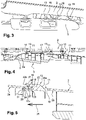
- the picture 3 presents a partial schematic view in perspective of the trim of a door 2 on which there is an armrest 3 to carry out its assembly on said door 2.
- the hooking elements 13 projecting from which are directed forwards in the longitudinal direction of the vehicle.
- the figure 4 shows a partial plan view from above of the internal face of a door 2 on which the armrest 3 shown partially is mounted in its position of use.
- the attachment elements 13 distributed inside the periphery of the armrest 3 are engaged and locked in retention means 17 provided at one end of the slots 11 of the armrest 3.
- the front end 5 of the armrest 3 comes to adjust and marry the curved shape 2a of the door 2.
- the figure 5 is an enlarged partial sectional view of an attachment element 13 engaged in a retention means 17 in the form of a prominence formed at the end of a slot 11 of the internal face 2a of a door 2.
- the armrest 3 is mounted in its position of use on the door 2 where it is fixed firmly.
- the door trim 2 comprises a plurality of slots 11 whose ends 18, 19 are oblique. End 18 is oblique on the outside while end 19 is oblique on the inside.
- the end 19 located forwards comprises a prominence 17 having on the outside at the base of the prominence 17 a hollow shape 20 limited by a shoulder 21.
- the hollow shape 20 is extended by a radius of curvature 17a on the current part of the prominence 17 to the oblique end 19 inside.
- the hooking element 13 is shaped to slide naturally into the slot 11 in the direction of longitudinal movement along the arrow 26. For this purpose, the hooking element 13 projects relative to the internal edge of the armrest 3 and comes from material with this one.
- the attachment element 13 has a profiled body 22 and its width is less than the width of the slot 11 so that it is introduced therein freely.
- the profiled body 22 has a chamfer 22a in its rear part suitable to cooperate with the oblique end 18 on the outside, while the front end comprises a beveled shape 16 whose end comprises a chamfer 22b capable of cooperating with the oblique end 19 on the inside so as to facilitate the introduction of the bevel 16.
- the bevel 16 generates a notch forming a housing 23, one wall 27 of which is inclined to cooperate with an inclined wall 28 of the prominence 17 which is introduced into the housing 23.
- the attachment elements 13 are distributed around the periphery of the armrest 3 and all oriented in the same direction. It is understood that to assemble the armrest 3 on the trim of the door 2, the armrest 3 is approached from the recessed zone 10, the hooking elements 13 are guided on the outer wall 25, while pushing the armrest on the lining, when the attachment elements 13 are facing the slots 11 they engage there naturally due to the cooperation of the chamfer 22a capable of cooperating with the oblique end 18 of the slot 11.
- bevel 16 comes cover the prominence 17 and is introduced into the housing 23.
- the wall 27 of the inclined bevel 16 cooperates with the inclined wall 28 of the prominence 17 on its inner surface, while the projection 24 placed on the outside engages in the hollow 20 allowing its locking. It is understood that the prominence 17 is engaged by force and it is immobilized by wedging between the bevel 16 and the projection 24 allowing the assembly and holding of the armrest 3 on the trim of the door 2.
- the couples of marked surfaces 22a, 18 cooperate with each other to facilitate the engagement of the hooking elements 13 in the slots 11.
- the pairs of marked surfaces 22b, 19 cooperate with each other to facilitate the engagement of the prominence 17 of the hooking elements 13 in the housing 23.
- the pairs of marked surfaces 20, 24 cooperate with each other to lock the hooking elements 13, when the pairs of marked surfaces 27, 28 cooperate together to block the prominences 17 of the hooking elements 13.
- the mounting of the armrest 3 is carried out by engaging the plurality of attachment elements 13 in the slots 11 along the longitudinal axis of the vehicle.
- the plurality of hooking elements 13 facilitates the mounting of the armrest 3 on the trim of the door 2 making it possible to obtain smooth guidance during assembly and robust coupling.
Description
L'invention se situe dans le domaine de l'aménagement intérieur d'un habitacle de véhicules notamment de permettre le choix et le montage d'une diversité d'accoudoirs sur un garnissage de portière de véhicule.The invention lies in the field of the interior fittings of a vehicle interior, in particular to allow the choice and mounting of a variety of armrests on a vehicle door trim.
L'invention porte également sur un véhicule automobile équipé d'un tel agencement.The invention also relates to a motor vehicle equipped with such an arrangement.
Généralement, les portières de véhicules sont livrées par le fournisseur de façon synchrone pour être assemblées sur les véhicules en cours de montage. Afin d'assurer le montage d'une diversité d'accoudoir sur une structure de portière de garnissage unique, il a été prévu de monter l'accoudoir sur la portière assemblée sur la ligne de montage. Le document
Le document
Dans ce contexte, la présente invention vise la conception d'un accoudoir répondant à ces exigences. L'accoudoir peut être facilement assemblé sur la portière déjà installée sur la ligne de montage pour pallier aux inconvénients de la diversité plus compliqué et plus onéreux à gérer chez le fournisseur et de plus il ne risque pas d'être éjecté en cas de choc sur la portière du véhicule.In this context, the present invention aims to design an armrest that meets these requirements. The armrest can be easily assembled on the door already installed on the assembly line to overcome the disadvantages of the more complicated and more expensive diversity to manage at the supplier's and moreover there is no risk of it being ejected in the event of an impact on the vehicle door.
A cet effet l'invention propose un agencement de l'assemblage d'un accoudoir sur la garniture d'une portière comportant ladite garniture et ledit accoudoir, l'accoudoir étant assemblé sur des moyens de rétention de la garniture de la portière, conçu sur un bord d'ouvertures par des moyens de clippage dirigés suivant une direction latérale de la portière qui correspond à la direction longitudinale de l'accoudoir. L'accoudoir est une coque. Les moyens de clippage sont constitués sous la forme d'éléments d'accroche comprenant un corps prolongé par un biseau et sont répartis sur le pourtour interne de la coque formant l'accoudoir.To this end, the invention proposes an arrangement for assembling an armrest on the trim of a door comprising said trim and said armrest, the armrest being assembled on means for retaining the trim of the door, designed on an edge of openings by clipping means directed in a lateral direction of the door which corresponds to the longitudinal direction of the armrest. The armrest is a shell. The means of clipping are formed in the form of attachment elements comprising a body extended by a bevel and are distributed over the internal periphery of the shell forming the armrest.
Selon une variante, les moyens de clippage sont en saillie par rapport au bord de l'accoudoir.According to a variant, the clipping means project relative to the edge of the armrest.
Selon une variante, l'élément d'accroche comporte un logement dont la largeur se rétrécit suivant une paroi inclinée en direction du fond.According to a variant, the hooking element comprises a housing, the width of which narrows along a wall inclined in the direction of the bottom.
Avantageusement, le logement comporte à proximité de son ouverture une saillie de forme carrée orientée vers l'extrémité du biseau.Advantageously, the housing has near its opening a square-shaped projection oriented towards the end of the bevel.
Selon une autre variante, les moyens de rétention sont constitués de proéminence à l'extrémité des ouvertures réparties sur la garniture de la portière de manière à permettre l'introduction d'éléments d'accroche.According to another variant, the retention means consist of prominence at the end of the openings distributed over the trim of the door so as to allow the introduction of attachment elements.
De façon avantageuse, les ouvertures sont des fentes comportant une extrémité oblique vers l'extérieur et une seconde extrémité oblique vers l'intérieur aptes à coopérer avec des chanfreins du moyen de clippage de façon à faciliter l'engagement des dits moyens de clippage sur les moyens de rétention.Advantageously, the openings are slots comprising an outwardly oblique end and an inwardly oblique second end suitable to cooperate with chamfers of the clipping means so as to facilitate engagement of said clipping means on the retention means.
Selon une autre variante, la paroi inclinée de la proéminence coopère avec la paroi inclinée ménagée sur le biseau lors de l'engagement de la saillie de forme carrée se verrouillant dans un creux localisé à la base de la proéminence, réalisant la tenue de l'accoudoir sur la garniture de la portière par coincement.According to another variant, the inclined wall of the prominence cooperates with the inclined wall provided on the bevel during the engagement of the square-shaped projection locking into a hollow located at the base of the prominence, carrying out the holding of the armrest on the door trim by wedging.
L'invention sera bien comprise et d'autres aspects et avantages apparaîtront clairement à la lecture de la description qui suit, donnée à titre d'exemple par rapport aux figures annexées sur lesquelles :
- La
figure 1 est une vue schématique en perspective de l'agencement du garnissage d'une portière apte à accueillir selon l'option le modèle d'accoudoir choisi dans une diversité de modèle ; - La
figure 2 est une vue schématique en perspective de l'intérieur d'un accoudoir sur lequel sont répartis les éléments d'accroches ; - La
figure 3 présente une vue schématique partielle en perspective du garnissage d'une portière sur laquelle, on présente un accoudoir pour effectuer son montage sur la portière ; - La
figure 4 présente une vue partielle en plan de dessus de la face interne d'une portière sur laquelle l'accoudoir représenté partiellement est monté dans sa position d'utilisation ; - La
figure 5 est une vue partielle en section agrandie d'un élément d'accroche en prise dans une proéminence ménagée dans l'ouverture la face interne d'une portière.
- The
figure 1 is a schematic perspective view of the arrangement of the upholstery of a door suitable for accommodating, depending on the option, the armrest model chosen from a variety of models; - The
figure 2 is a schematic perspective view of the interior of an armrest on which the attachment elements are distributed; - The
picture 3 - The
figure 4 shows a partial plan view from above of the internal face of a door on which the armrest shown partially is mounted in its position of use; - The
figure 5 is a partial enlarged sectional view of an attachment element engaged in a prominence made in the opening on the inner face of a door.
La
La
La
La
La
Claims (8)
- Arrangement (1) for assembling an armrest (3) to the lining of a door (2), the arrangement (1) comprising said lining (2) and said armrest (3), characterized in that the armrest (3) is a shell, and is assembled on means (17) for retaining the lining of the door (2) designed on an edge of openings (11), by clipping means (13) directed along a lateral direction of the door (2) which corresponds to the longitudinal direction of the armrest (3), clipping means (13) being constituted in the form of hooking elements comprising a body (22) extended by a bevel (16) and are distributed over the inner periphery of the shell forming the armrest (3).
- Arrangement (1) according to claim 1, characterized in that the clipping means (13) project from the edge of the armrest (3).
- Arrangement (1) according to one of Claims 1 or 2, characterized in that the fastening element (13) has a receptacle (23), the width of which narrows along a wall inclined towards the bottom.
- Arrangement (1) according to claim 3, characterized in that the housing (23) has a square-shaped projection (24) in the vicinity of its opening (11), which projection (24) faces the end of the bevel (16).
- Arrangement (1) according to one of Claims 1 to 4, characterized in that the retaining means (17) are formed by protrusions at the end of the openings (11) distributed over the door lining (2) so as to allow the insertion of the fastening elements (13).
- An arrangement (1) according to claim 5, characterized in that the openings (11) are slots having an outwardly oblique end (18) and a second inwardly oblique end (19) adapted to cooperate with chamfers (22a, 22b) of the clipping means (13) so as to facilitate the engagement of said clipping means (13) on the projection (17).
- Arrangement (1) according to either of Claims 5 and 6, characterized in that the protuberance (17) has on its internal surface an inclined wall (28) able to cooperate with the inclined wall (27) of the clipping means (13).
- Arrangement (1) according to Claim 7, characterized in that the inclined wall (28) of the projection (17) cooperates with the inclined wall (27) formed on the bevel (16) when the square-shaped projection (24) is engaged and locks into a recess (20) located at the base of the projection (17), thereby holding the armrest (3) on the door lining (2) by wedging.
Applications Claiming Priority (2)
| Application Number | Priority Date | Filing Date | Title |
|---|---|---|---|
| FR1561954A FR3044615B1 (en) | 2015-12-08 | 2015-12-08 | ARRANGEMENT FOR MOUNTING AN ARMREST ON A VEHICLE DOOR |
| PCT/FR2016/053279 WO2017098167A1 (en) | 2015-12-08 | 2016-12-08 | Arrangement for mounting an armrest on a vehicle door |
Publications (2)
| Publication Number | Publication Date |
|---|---|
| EP3386795A1 EP3386795A1 (en) | 2018-10-17 |
| EP3386795B1 true EP3386795B1 (en) | 2022-10-26 |
Family
ID=55806449
Family Applications (1)
| Application Number | Title | Priority Date | Filing Date |
|---|---|---|---|
| EP16819996.6A Active EP3386795B1 (en) | 2015-12-08 | 2016-12-08 | Arrangement for mounting an armrest on a vehicle door |
Country Status (4)
| Country | Link |
|---|---|
| EP (1) | EP3386795B1 (en) |
| CN (1) | CN108463372B (en) |
| FR (1) | FR3044615B1 (en) |
| WO (1) | WO2017098167A1 (en) |
Families Citing this family (1)
| Publication number | Priority date | Publication date | Assignee | Title |
|---|---|---|---|---|
| CN108819810A (en) * | 2018-05-14 | 2018-11-16 | 江苏派欧汽车零部件有限公司 | Left front door armrest skeleton |
Family Cites Families (8)
| Publication number | Priority date | Publication date | Assignee | Title |
|---|---|---|---|---|
| DE3500392A1 (en) * | 1985-01-08 | 1986-07-10 | Gebr. Happich Gmbh, 5600 Wuppertal | UPHOLSTERY BODY FOR THE INTERIOR OF VEHICLES |
| JP3555292B2 (en) * | 1996-01-11 | 2004-08-18 | 日産自動車株式会社 | Vehicle armrest |
| JP4150438B2 (en) * | 1997-12-26 | 2008-09-17 | テイ・エス テック株式会社 | Clip mounting seat for automotive interior parts |
| CN1894124B (en) * | 2003-08-22 | 2013-04-24 | 索斯科公司 | Rotary pawl latch with lock down paddle |
| KR100571669B1 (en) * | 2004-08-16 | 2006-04-18 | 현대자동차주식회사 | Door pull handle mounting means of automobile |
| DE102006058491B4 (en) * | 2006-10-02 | 2018-03-15 | Johnson Controls Interiors Gmbh & Co. Kg | Multi-part vehicle equipment part and connection method |
| JP5420969B2 (en) * | 2009-05-12 | 2014-02-19 | トヨタ紡織株式会社 | Vehicle door trim |
| CN204605598U (en) * | 2015-02-13 | 2015-09-02 | 福州联泓交通器材有限公司 | A kind of automotive seat with movable armrest |
-
2015
- 2015-12-08 FR FR1561954A patent/FR3044615B1/en not_active Expired - Fee Related
-
2016
- 2016-12-08 EP EP16819996.6A patent/EP3386795B1/en active Active
- 2016-12-08 CN CN201680072112.5A patent/CN108463372B/en active Active
- 2016-12-08 WO PCT/FR2016/053279 patent/WO2017098167A1/en active Application Filing
Also Published As
| Publication number | Publication date |
|---|---|
| WO2017098167A1 (en) | 2017-06-15 |
| FR3044615B1 (en) | 2018-07-20 |
| CN108463372A (en) | 2018-08-28 |
| EP3386795A1 (en) | 2018-10-17 |
| FR3044615A1 (en) | 2017-06-09 |
| CN108463372B (en) | 2021-08-24 |
Similar Documents
| Publication | Publication Date | Title |
|---|---|---|
| FR2761127A1 (en) | Insert for fixing articles on surfaces, e.g. blind holes, on motor vehicles, in vehicle assembly lines | |
| FR3000771A1 (en) | CLAMP FOR ATTACHING A PANEL TO A SUPPORT AND ASSEMBLY OBTAINED | |
| FR3002754A1 (en) | SEAT FOR A MOTOR VEHICLE HAVING A FOLDER MEMBER WITH A REMOVABLE PART PROVIDED WITH STORAGE MEANS | |
| WO2019135035A1 (en) | Attaching and guiding device for cable bundles which travel between a spar and the trim lining thereof | |
| EP3386795B1 (en) | Arrangement for mounting an armrest on a vehicle door | |
| EP2658741B1 (en) | Device helping guiding of a safety belt tongue for child booster seat | |
| WO2016012680A1 (en) | Safety device having an interface part positioned with respect to the airbag housing, for a vehicle seat | |
| FR3002756A1 (en) | MOTOR VEHICLE SEAT WITH RETURNABLE SEATING ELEMENT WITH AN OPENING FOR THE PASSAGE OF A SAFETY BELT FASTENING BASE | |
| WO2018015691A1 (en) | Headrest for a motor vehicle seat | |
| FR2999024A1 (en) | Electrical apparatus e.g. plug, has side extension including lower edge fixed to support, and mechanism attached to side extension and partially accommodated in inner space delimited by contour of side extension | |
| EP3118062A1 (en) | Device for covering a luggage compartment of a motor vehicle | |
| EP1655430A1 (en) | Device for preventing unauthorised operation of the bonnet closure cable of a motor vehicle | |
| WO2018150126A1 (en) | Electric heating device comprising a device for limiting the movements of a heating element | |
| FR3070638B1 (en) | DEVICE FOR TOWING A REMOVABLE SEAT AT A FLOOR OF A MOTOR VEHICLE. | |
| WO2003063667A1 (en) | Detachable handle for a cooking utensil | |
| FR2903533A1 (en) | Electrical cable retaining ring for use on bulkhead of motor vehicle, has secondary plate detachably fixed to main plate or to slot, and receiving oval shaped element with sealing opposite to that of main plate, by hole of secondary plate | |
| EP1717106A1 (en) | Arrangement for supporting an electronic housing in a vehicle | |
| EP3233586B1 (en) | Steering column lock | |
| FR3102106A1 (en) | DEVICE FOR FIXING A BENCH SEAT ON A MOTOR VEHICLE FRAME | |
| FR2868371A1 (en) | Motor vehicle rooftop bar mounting assembly, has fixing unit with passage opening and plate`s lower side equipped with housings for receiving sealing unit around opening and forming support surface on roof of motor vehicle | |
| FR3140331A1 (en) | SHUTTER FOR INTERIOR TRIM OF A MOTOR VEHICLE AND MOTOR VEHICLE EQUIPPED WITH SUCH A SHUTTER | |
| FR3040669A1 (en) | AUTOMOTIVE VEHICLE LUGGAGE COMPARTMENT REPAIR SYSTEM | |
| FR3098475A1 (en) | VEHICLE DASHBOARD DESIGNED TO HOLD MOBILE OBJECTS | |
| EP2076407B1 (en) | Interface piece for asssembly of an element in an opening in a circuit board | |
| EP2463529A1 (en) | Attachment device with reinforced locking |
Legal Events
| Date | Code | Title | Description |
|---|---|---|---|
| STAA | Information on the status of an ep patent application or granted ep patent |
Free format text: STATUS: UNKNOWN |
|
| STAA | Information on the status of an ep patent application or granted ep patent |
Free format text: STATUS: THE INTERNATIONAL PUBLICATION HAS BEEN MADE |
|
| PUAI | Public reference made under article 153(3) epc to a published international application that has entered the european phase |
Free format text: ORIGINAL CODE: 0009012 |
|
| STAA | Information on the status of an ep patent application or granted ep patent |
Free format text: STATUS: REQUEST FOR EXAMINATION WAS MADE |
|
| 17P | Request for examination filed |
Effective date: 20180705 |
|
| AK | Designated contracting states |
Kind code of ref document: A1 Designated state(s): AL AT BE BG CH CY CZ DE DK EE ES FI FR GB GR HR HU IE IS IT LI LT LU LV MC MK MT NL NO PL PT RO RS SE SI SK SM TR |
|
| AX | Request for extension of the european patent |
Extension state: BA ME |
|
| RIC1 | Information provided on ipc code assigned before grant |
Ipc: B60N 2/46 20060101AFI20170706BHEP |
|
| DAV | Request for validation of the european patent (deleted) | ||
| DAX | Request for extension of the european patent (deleted) | ||
| RAP1 | Party data changed (applicant data changed or rights of an application transferred) |
Owner name: PSA AUTOMOBILES SA Owner name: SIMOLDES PLASTICOS, SA |
|
| STAA | Information on the status of an ep patent application or granted ep patent |
Free format text: STATUS: EXAMINATION IS IN PROGRESS |
|
| 17Q | First examination report despatched |
Effective date: 20201210 |
|
| REG | Reference to a national code |
Ref country code: DE Ref legal event code: R079 Ref document number: 602016075930 Country of ref document: DE Free format text: PREVIOUS MAIN CLASS: B60N0002460000 Ipc: B60N0002750000 |
|
| RIC1 | Information provided on ipc code assigned before grant |
Ipc: B60N 2/75 20180101AFI20211007BHEP |
|
| STAA | Information on the status of an ep patent application or granted ep patent |
Free format text: STATUS: EXAMINATION IS IN PROGRESS |
|
| GRAP | Despatch of communication of intention to grant a patent |
Free format text: ORIGINAL CODE: EPIDOSNIGR1 |
|
| STAA | Information on the status of an ep patent application or granted ep patent |
Free format text: STATUS: GRANT OF PATENT IS INTENDED |
|
| INTG | Intention to grant announced |
Effective date: 20220627 |
|
| GRAS | Grant fee paid |
Free format text: ORIGINAL CODE: EPIDOSNIGR3 |
|
| GRAA | (expected) grant |
Free format text: ORIGINAL CODE: 0009210 |
|
| STAA | Information on the status of an ep patent application or granted ep patent |
Free format text: STATUS: THE PATENT HAS BEEN GRANTED |
|
| AK | Designated contracting states |
Kind code of ref document: B1 Designated state(s): AL AT BE BG CH CY CZ DE DK EE ES FI FR GB GR HR HU IE IS IT LI LT LU LV MC MK MT NL NO PL PT RO RS SE SI SK SM TR |
|
| REG | Reference to a national code |
Ref country code: GB Ref legal event code: FG4D Free format text: NOT ENGLISH |
|
| REG | Reference to a national code |
Ref country code: CH Ref legal event code: EP |
|
| REG | Reference to a national code |
Ref country code: DE Ref legal event code: R096 Ref document number: 602016075930 Country of ref document: DE |
|
| REG | Reference to a national code |
Ref country code: AT Ref legal event code: REF Ref document number: 1526819 Country of ref document: AT Kind code of ref document: T Effective date: 20221115 |
|
| REG | Reference to a national code |
Ref country code: IE Ref legal event code: FG4D Free format text: LANGUAGE OF EP DOCUMENT: FRENCH |
|
| REG | Reference to a national code |
Ref country code: LT Ref legal event code: MG9D |
|
| REG | Reference to a national code |
Ref country code: NL Ref legal event code: MP Effective date: 20221026 |
|
| REG | Reference to a national code |
Ref country code: AT Ref legal event code: MK05 Ref document number: 1526819 Country of ref document: AT Kind code of ref document: T Effective date: 20221026 |
|
| REG | Reference to a national code |
Ref country code: SK Ref legal event code: T3 Ref document number: E 41156 Country of ref document: SK |
|
| PG25 | Lapsed in a contracting state [announced via postgrant information from national office to epo] |
Ref country code: NL Free format text: LAPSE BECAUSE OF FAILURE TO SUBMIT A TRANSLATION OF THE DESCRIPTION OR TO PAY THE FEE WITHIN THE PRESCRIBED TIME-LIMIT Effective date: 20221026 |
|
| PG25 | Lapsed in a contracting state [announced via postgrant information from national office to epo] |
Ref country code: SE Free format text: LAPSE BECAUSE OF FAILURE TO SUBMIT A TRANSLATION OF THE DESCRIPTION OR TO PAY THE FEE WITHIN THE PRESCRIBED TIME-LIMIT Effective date: 20221026 Ref country code: PT Free format text: LAPSE BECAUSE OF FAILURE TO SUBMIT A TRANSLATION OF THE DESCRIPTION OR TO PAY THE FEE WITHIN THE PRESCRIBED TIME-LIMIT Effective date: 20230227 Ref country code: NO Free format text: LAPSE BECAUSE OF FAILURE TO SUBMIT A TRANSLATION OF THE DESCRIPTION OR TO PAY THE FEE WITHIN THE PRESCRIBED TIME-LIMIT Effective date: 20230126 Ref country code: LT Free format text: LAPSE BECAUSE OF FAILURE TO SUBMIT A TRANSLATION OF THE DESCRIPTION OR TO PAY THE FEE WITHIN THE PRESCRIBED TIME-LIMIT Effective date: 20221026 Ref country code: FI Free format text: LAPSE BECAUSE OF FAILURE TO SUBMIT A TRANSLATION OF THE DESCRIPTION OR TO PAY THE FEE WITHIN THE PRESCRIBED TIME-LIMIT Effective date: 20221026 Ref country code: ES Free format text: LAPSE BECAUSE OF FAILURE TO SUBMIT A TRANSLATION OF THE DESCRIPTION OR TO PAY THE FEE WITHIN THE PRESCRIBED TIME-LIMIT Effective date: 20221026 Ref country code: AT Free format text: LAPSE BECAUSE OF FAILURE TO SUBMIT A TRANSLATION OF THE DESCRIPTION OR TO PAY THE FEE WITHIN THE PRESCRIBED TIME-LIMIT Effective date: 20221026 |
|
| PG25 | Lapsed in a contracting state [announced via postgrant information from national office to epo] |
Ref country code: RS Free format text: LAPSE BECAUSE OF FAILURE TO SUBMIT A TRANSLATION OF THE DESCRIPTION OR TO PAY THE FEE WITHIN THE PRESCRIBED TIME-LIMIT Effective date: 20221026 Ref country code: PL Free format text: LAPSE BECAUSE OF FAILURE TO SUBMIT A TRANSLATION OF THE DESCRIPTION OR TO PAY THE FEE WITHIN THE PRESCRIBED TIME-LIMIT Effective date: 20221026 Ref country code: LV Free format text: LAPSE BECAUSE OF FAILURE TO SUBMIT A TRANSLATION OF THE DESCRIPTION OR TO PAY THE FEE WITHIN THE PRESCRIBED TIME-LIMIT Effective date: 20221026 Ref country code: IS Free format text: LAPSE BECAUSE OF FAILURE TO SUBMIT A TRANSLATION OF THE DESCRIPTION OR TO PAY THE FEE WITHIN THE PRESCRIBED TIME-LIMIT Effective date: 20230226 Ref country code: HR Free format text: LAPSE BECAUSE OF FAILURE TO SUBMIT A TRANSLATION OF THE DESCRIPTION OR TO PAY THE FEE WITHIN THE PRESCRIBED TIME-LIMIT Effective date: 20221026 Ref country code: GR Free format text: LAPSE BECAUSE OF FAILURE TO SUBMIT A TRANSLATION OF THE DESCRIPTION OR TO PAY THE FEE WITHIN THE PRESCRIBED TIME-LIMIT Effective date: 20230127 |
|
| REG | Reference to a national code |
Ref country code: DE Ref legal event code: R097 Ref document number: 602016075930 Country of ref document: DE |
|
| PG25 | Lapsed in a contracting state [announced via postgrant information from national office to epo] |
Ref country code: SM Free format text: LAPSE BECAUSE OF FAILURE TO SUBMIT A TRANSLATION OF THE DESCRIPTION OR TO PAY THE FEE WITHIN THE PRESCRIBED TIME-LIMIT Effective date: 20221026 Ref country code: RO Free format text: LAPSE BECAUSE OF FAILURE TO SUBMIT A TRANSLATION OF THE DESCRIPTION OR TO PAY THE FEE WITHIN THE PRESCRIBED TIME-LIMIT Effective date: 20221026 Ref country code: EE Free format text: LAPSE BECAUSE OF FAILURE TO SUBMIT A TRANSLATION OF THE DESCRIPTION OR TO PAY THE FEE WITHIN THE PRESCRIBED TIME-LIMIT Effective date: 20221026 Ref country code: DK Free format text: LAPSE BECAUSE OF FAILURE TO SUBMIT A TRANSLATION OF THE DESCRIPTION OR TO PAY THE FEE WITHIN THE PRESCRIBED TIME-LIMIT Effective date: 20221026 Ref country code: CZ Free format text: LAPSE BECAUSE OF FAILURE TO SUBMIT A TRANSLATION OF THE DESCRIPTION OR TO PAY THE FEE WITHIN THE PRESCRIBED TIME-LIMIT Effective date: 20221026 |
|
| REG | Reference to a national code |
Ref country code: CH Ref legal event code: PL |
|
| REG | Reference to a national code |
Ref country code: BE Ref legal event code: MM Effective date: 20221231 |
|
| PG25 | Lapsed in a contracting state [announced via postgrant information from national office to epo] |
Ref country code: LU Free format text: LAPSE BECAUSE OF NON-PAYMENT OF DUE FEES Effective date: 20221208 Ref country code: AL Free format text: LAPSE BECAUSE OF FAILURE TO SUBMIT A TRANSLATION OF THE DESCRIPTION OR TO PAY THE FEE WITHIN THE PRESCRIBED TIME-LIMIT Effective date: 20221026 |
|
| PLBE | No opposition filed within time limit |
Free format text: ORIGINAL CODE: 0009261 |
|
| STAA | Information on the status of an ep patent application or granted ep patent |
Free format text: STATUS: NO OPPOSITION FILED WITHIN TIME LIMIT |
|
| 26N | No opposition filed |
Effective date: 20230727 |
|
| PG25 | Lapsed in a contracting state [announced via postgrant information from national office to epo] |
Ref country code: LI Free format text: LAPSE BECAUSE OF NON-PAYMENT OF DUE FEES Effective date: 20221231 Ref country code: IE Free format text: LAPSE BECAUSE OF NON-PAYMENT OF DUE FEES Effective date: 20221208 Ref country code: CH Free format text: LAPSE BECAUSE OF NON-PAYMENT OF DUE FEES Effective date: 20221231 |
|
| PG25 | Lapsed in a contracting state [announced via postgrant information from national office to epo] |
Ref country code: SI Free format text: LAPSE BECAUSE OF FAILURE TO SUBMIT A TRANSLATION OF THE DESCRIPTION OR TO PAY THE FEE WITHIN THE PRESCRIBED TIME-LIMIT Effective date: 20221026 Ref country code: BE Free format text: LAPSE BECAUSE OF NON-PAYMENT OF DUE FEES Effective date: 20221231 |
|
| PGFP | Annual fee paid to national office [announced via postgrant information from national office to epo] |
Ref country code: SK Payment date: 20231128 Year of fee payment: 8 |
|
| PGFP | Annual fee paid to national office [announced via postgrant information from national office to epo] |
Ref country code: GB Payment date: 20231121 Year of fee payment: 8 |
|
| PGFP | Annual fee paid to national office [announced via postgrant information from national office to epo] |
Ref country code: FR Payment date: 20231122 Year of fee payment: 8 Ref country code: DE Payment date: 20231121 Year of fee payment: 8 |
|
| PG25 | Lapsed in a contracting state [announced via postgrant information from national office to epo] |
Ref country code: HU Free format text: LAPSE BECAUSE OF FAILURE TO SUBMIT A TRANSLATION OF THE DESCRIPTION OR TO PAY THE FEE WITHIN THE PRESCRIBED TIME-LIMIT; INVALID AB INITIO Effective date: 20161208 |