EP2657073A1 - Headrest device - Google Patents
Headrest device Download PDFInfo
- Publication number
- EP2657073A1 EP2657073A1 EP13164405.6A EP13164405A EP2657073A1 EP 2657073 A1 EP2657073 A1 EP 2657073A1 EP 13164405 A EP13164405 A EP 13164405A EP 2657073 A1 EP2657073 A1 EP 2657073A1
- Authority
- EP
- European Patent Office
- Prior art keywords
- headrest
- head
- support face
- internal structure
- end portion
- Prior art date
- Legal status (The legal status is an assumption and is not a legal conclusion. Google has not performed a legal analysis and makes no representation as to the accuracy of the status listed.)
- Granted
Links
- 238000005452 bending Methods 0.000 description 20
- 230000005484 gravity Effects 0.000 description 6
- 230000000052 comparative effect Effects 0.000 description 5
- 239000006260 foam Substances 0.000 description 5
- JOYRKODLDBILNP-UHFFFAOYSA-N Ethyl urethane Chemical compound CCOC(N)=O JOYRKODLDBILNP-UHFFFAOYSA-N 0.000 description 4
- 239000000463 material Substances 0.000 description 4
- 230000002093 peripheral effect Effects 0.000 description 3
- 230000008878 coupling Effects 0.000 description 2
- 238000010168 coupling process Methods 0.000 description 2
- 238000005859 coupling reaction Methods 0.000 description 2
- 239000002184 metal Substances 0.000 description 2
- 230000001681 protective effect Effects 0.000 description 2
- 238000010521 absorption reaction Methods 0.000 description 1
- 238000006243 chemical reaction Methods 0.000 description 1
- 230000000694 effects Effects 0.000 description 1
- 239000004744 fabric Substances 0.000 description 1
- 239000006261 foam material Substances 0.000 description 1
- 238000005187 foaming Methods 0.000 description 1
- 239000010985 leather Substances 0.000 description 1
- 239000002649 leather substitute Substances 0.000 description 1
- 238000004519 manufacturing process Methods 0.000 description 1
- 238000000034 method Methods 0.000 description 1
- 238000012986 modification Methods 0.000 description 1
- 230000004048 modification Effects 0.000 description 1
- 238000000465 moulding Methods 0.000 description 1
- 238000003466 welding Methods 0.000 description 1
Images



Classifications
-
- A—HUMAN NECESSITIES
- A47—FURNITURE; DOMESTIC ARTICLES OR APPLIANCES; COFFEE MILLS; SPICE MILLS; SUCTION CLEANERS IN GENERAL
- A47C—CHAIRS; SOFAS; BEDS
- A47C7/00—Parts, details, or accessories of chairs or stools
- A47C7/36—Supports for the head or the back
- A47C7/38—Supports for the head or the back for the head, e.g. detachable
-
- B—PERFORMING OPERATIONS; TRANSPORTING
- B60—VEHICLES IN GENERAL
- B60N—SEATS SPECIALLY ADAPTED FOR VEHICLES; VEHICLE PASSENGER ACCOMMODATION NOT OTHERWISE PROVIDED FOR
- B60N2/00—Seats specially adapted for vehicles; Arrangement or mounting of seats in vehicles
- B60N2/24—Seats specially adapted for vehicles; Arrangement or mounting of seats in vehicles for particular purposes or particular vehicles
- B60N2/42—Seats specially adapted for vehicles; Arrangement or mounting of seats in vehicles for particular purposes or particular vehicles the seat constructed to protect the occupant from the effect of abnormal g-forces, e.g. crash or safety seats
- B60N2/4207—Seats specially adapted for vehicles; Arrangement or mounting of seats in vehicles for particular purposes or particular vehicles the seat constructed to protect the occupant from the effect of abnormal g-forces, e.g. crash or safety seats characterised by the direction of the g-forces
- B60N2/4214—Seats specially adapted for vehicles; Arrangement or mounting of seats in vehicles for particular purposes or particular vehicles the seat constructed to protect the occupant from the effect of abnormal g-forces, e.g. crash or safety seats characterised by the direction of the g-forces longitudinal
- B60N2/4228—Seats specially adapted for vehicles; Arrangement or mounting of seats in vehicles for particular purposes or particular vehicles the seat constructed to protect the occupant from the effect of abnormal g-forces, e.g. crash or safety seats characterised by the direction of the g-forces longitudinal due to impact coming from the rear
-
- B—PERFORMING OPERATIONS; TRANSPORTING
- B60—VEHICLES IN GENERAL
- B60N—SEATS SPECIALLY ADAPTED FOR VEHICLES; VEHICLE PASSENGER ACCOMMODATION NOT OTHERWISE PROVIDED FOR
- B60N2/00—Seats specially adapted for vehicles; Arrangement or mounting of seats in vehicles
- B60N2/80—Head-rests
- B60N2/888—Head-rests with arrangements for protecting against abnormal g-forces, e.g. by displacement of the head-rest
Definitions
- the present invention relates to a headrest device.
- a core member configured from for example a hard urethane foam is fixed at an upper end side of a stay.
- An upper portion of a front face of the core member is formed with a protrusion that protrudes out toward the front, and a lower portion of the front face is formed with a recess.
- a pad portion is made thickest at a location in front of the recess, and this thick portion of the pad secures comfort of an occupant during normal use.
- a subject of the present invention is to obtain a headrest device that can raise protection performance with respect to the neck of an occupant.
- a headrest device includes: a headrest stay that is coupled to an upper end portion of a seatback of a vehicle seat, and that supports a headrest pad; an internal structure that is embedded inside the headrest pad, that is supported from a rear by the headrest stay, and that supports a head of an occupant from the rear during a vehicle rear-on collision via a support face that is formed at a front face of the internal structure; and a forward projection portion that is configured by a portion of the headrest stay that projects forward, and that is disposed at an upper side or a lower side of the support face within the headrest pad, and that suppresses the head supported by the support face from tilting backward or tilting forward by pivoting about the support face as pivoting center.
- front-rear and up-down directions in the first aspect are front-rear and up-down directions of the vehicle.
- a height of the headrest pad with respect to the seatback and the recline angle of the seatback are adjusted such that a central portion of a front face of the headrest pad faces a central portion of a back face of the head of the occupant from the rear.
- the head of the occupant is supported by the support face of the internal structure through the headrest pad during a vehicle rear-on collision.
- the forward projection portion configured by a portion of the headrest stay is disposed at the upper side or the lower side of the support face.
- the forward projection portion suppresses the head that is supported by the support face from tilting backward or tilting forward by pivoting about the support face. Accordingly, the direction and strength of head tilting can be controlled by setting position of a front end portion of the forward projection portion depending on a collision speed in a rear-on collision and depending on differences between vehicle seats. Since the absolute value of the bending moment arising on the neck of the occupant can be reduced, protection performance with respect to the neck can be improved as a result.
- a headrest device includes: a headrest stay that is coupled to an upper end portion of a seatback of a vehicle seat, and that supports a headrest pad; an internal structure that is embedded inside the headrest pad, that is supported from a rear by the headrest stay, and that supports a head of an occupant from the rear during a vehicle rear-on collision via a support face that is formed at a front face of the internal structure; and a forward projection portion that is configured by a portion of the headrest stay that projects forward, that is disposed at an upper side or a lower side of the support face within the headrest pad, and wherein a front end portion of the forward projection portion is disposed so as to face, from the rear, the head that is supported by the support face.
- the head of the occupant is supported by the support face of the internal structure through the headrest pad during a vehicle rear-on collision.
- the forward projection portion configured by a portion of the headrest stay is disposed to the upper side or the lower side of the support face, and the front end portion of the forward projection portion faces the head from the rear.
- the forward projection portion is accordingly able to suppress the head that is supported by the support face of the internal structure from tilting backward or tilting forward by pivoting about the support face. Accordingly, the direction and strength of head tilting can be controlled by setting position of a front end portion of the forward projection portion depending on a collision speed in a rear-on collision and depending on differences between vehicle seats. Since the absolute value of the bending moment arising on the neck of the occupant can be reduced, protection performance with respect to the neck can be improved as a result.
- a headrest device is the headrest device of the first aspect or the second aspect, wherein a front end portion of the forward projection portion projects out further forward than the support face of the internal structure.
- the forward projection portion of the headrest projects out toward the front at the upper side or the lower side of the support face of the internal structure.
- the front end portion of the forward projection portion projects out further toward the front than the support face.
- the front end portion of the forward projection portion can accordingly be placed in close proximity to and facing a portion of the head of the occupant on the upper side or the lower side of a rear end portion of the head when the rear end portion of the head of the occupant, namely the portion of the head projecting furthest toward the rear, is being supported by the support face.
- the head can accordingly be efficiently suppressed from tilting forward or tilting backward by pivoting about the support face.
- a headrest device is capable of improving the protection performance with respect to the neck of an occupant.
- an arrow FR indicates a vehicle front direction
- an arrow UP indicates a vehicle upwards direction
- an angle LH indicates a vehicle left hand direction
- an angle RH indicates a vehicle right hand direction as appropriate.
- front-rear, up-down or left-right directions these can be considered to be the front and rear in the vehicle front-rear direction, up and down in the vehicle up-down direction, and left and right in the vehicle left-right direction (the vehicle width direction).
- the headrest device 10 of the present exemplary embodiment is attached at an upper end portion of a seatback 14 of a vehicle seat 12.
- the headrest device 10 is configured by a headrest stay 16 serving as a framework member, a headrest pad 18 that is a cushion member, a cover 20 configuring a design face, and an internal structure 22 serving as an impact absorption member.
- vehicle seat 12 is coupled to a vehicle body floor section, not shown in the drawings, such that an occupant 24 sits facing the front.
- the front-rear, up-down and left-right directions of the vehicle seat 12 accordingly match the front-rear, up-down and left-right directions of the vehicle.
- the headrest stay 16 is formed for example by bend-working metal piping, and is formed in an inverted substantially U shape as viewed along the front-rear direction.
- the headrest stay 16 is configured by a left and right pair of leg portions 16L, and a connecting portion 16U that connects together upper end portions of the left and right leg portions 16L in the left-right direction.
- the left and right leg portions 16L are bent slightly in a vicinity of a top-bottom direction central portion as viewed from the side, as shown in Fig. 1 . Upper end sides of the bent portions are inclined toward the front on progression toward an upper side.
- lower end sides of the left and right leg portions 16L are coupled to headrest supports 26 provided at an upper end portion of the seatback 14.
- the headrest supports 26 are mounted to headrest support brackets 30 that are fixed to an upper end portion of a seatback frame 28 that serves as a framework member of the seatback 14.
- the lower end sides of the headrest stay 16 are accordingly coupled to the upper end portion of the seatback frame 28 through the headrest supports 26 and the headrest support brackets 30 so as to be height-adjustable.
- the headrest pad 18 is configured from a resilient foam material such as a urethane foam, and an upper end side of the headrest stay 16 is embedded in the headrest pad 18.
- the headrest pad 18 is accordingly supported by the headrest stay 16.
- the surface of the headrest pad 18 is covered by the cover 20 that is sewn into a bag shape from a material such as cloth, leather or synthetic leather. Note that in the present exemplary embodiment, the height of the headrest pad 18 with respect to the seatback 14 and a reclining angle of the seatback 14 (an angle of inclination with respect to a seat cushion, not shown in the drawings) are adjusted such that a front face central portion of the headrest pad 18 faces a central portion of a back of the head H of the occupant 24 from the rear.
- the internal structure 22 is embedded inside the headrest pad 18.
- the internal structure 22 is formed from a hard material such as a hard urethane foam in a substantially block shape that is smaller than the headrest pad 18.
- the internal structure 22 is attached to the headrest stay 16 by for example fitting the left and right leg portions 16L of the headrest stay 16 into a left and right pair of vertical grooves formed on a rear face side of the internal structure 22. The internal structure 22 is thus supported from the rear side by the headrest stay 16.
- the front face of the internal structure 22 is formed with a curved face shape following a front face portion 20A of the cover 20.
- a portion of substantially uniform thickness of the headrest pad 18 is interposed between the front face of the internal structure 22 and the front face portion 20A.
- a support face 22A provided at an upper portion side of the front face of the internal structure 22 is disposed at a substantially equivalent height to the center of gravity G of the head H of the occupant 24.
- the height of the center of gravity G is at substantially the same height as a rearmost end portion of the head H of the occupant 24, namely the portion of the head H that protrudes furthest toward the rear.
- configuration is made such that when the vehicle is involved in a rear-on collision, the headrest pad 18 is squashed under load from the head H of the occupant 24 moving toward the rear under inertia, and a rear end portion of the head H is supported from the rear by the support face 22A of the internal structure 22 (the head H receives a reaction force toward the front from the support face 22A).
- the upper end side of the headrest stay 16 to which the internal structure 22 is attached is inserted inside the cover 20 and set in a mold, not shown in the drawings. Integral molding is performed in this state by injecting a foaming material for the headrest pad 18 into the cover 20 and causing the material to foam and expand.
- the upper end portions of the left and right leg portions 16L of the headrest stay 16 are bent toward the front.
- a forward projection portion 17 is formed thereby at the upper end portion of the headrest stay 16.
- the forward projection portion 17 is configured by portions of the left and right leg portions 16L and the connecting portion 16U.
- the portions of the left and right leg portions 16L extend further toward a connecting portion 16U side from bent portions 16B positioned at upper end portions of the left and right leg portions 16L,.
- the forward projection portion 17 is formed in a substantially U-shape that is open toward the rear as viewed in plane view.
- the forward projection portion 17 is configured by a portion of the headrest stay 16, and is accordingly the same rigid body as the headrest stay 16.
- the forward projection portion 17 described above is disposed further at an upper side than the internal structure 22, and projects out toward the front (to the front face portion 20A side).
- a front end portion of the forward projection portion 17 (the coupling portion 16U) projects out slightly further to the front than the front end of the support face 22A.
- the position of the connecting portion 16U is configured such that a front end portion of the connecting portion 16U is at a position facing the head H that is supported by the support face 22A from the rear in the rear-on collision as described above. Namely, the front end portion of the connecting portion 16U is at a position that suppresses the head H supported by the support face 22A from tilting backward by pivoting about the support face 22A.
- Detailed explanation follows regarding setting the position (placement) of the forward projection portion 17.
- a bending moment (My) arises on a neck of the occupant 24 due to the head H of the occupant 24 tilting backward or tilting forward.
- the value of the bending moment (My) varies depending on the collision speed of the rear-on collision, and on differences in the vehicle seat structure.
- the broken line in Fig. 4 shows the bending moment (My) in a case for a vehicle seat 12 of the present exemplary embodiment that however, does not have the upper end portion of the headrest stay 16 bent toward the front and that has the forward projection portion 17 omitted (referred to below as the Comparative Example).
- the moderate speed, low speed and high speed shown in Fig. 4 illustrate differences in the collision speed in a rear-on collision.
- the bending moment (My) is unevenly distributed at a negative side in the Comparative Example.
- the head H of the occupant 24 is tilted backward so as to raise a chin (make the chin stick out).
- the bending moment (My) is positive, the head H of the occupant 24 is tilted forward such that the chin is pulled in.
- the head H of the occupant 24 tends to be tilted backward such that the chin is raised no matter whether the collision speed is a moderate speed, a high speed, or a low speed.
- bending moment (My) values increases in the sequence of moderate speed, low speed, and high speed.
- Protective performance for the neck N can be improved the closer the bending moment (My) is to zero.
- the position of the forward projection portion 17 is determined so as to make the bending moment (My) closer to zero in all three speeds of the above collision.
- the position in the up-down direction of the forward projection portion 17 is set at a position in a region of tens of mm higher that the center of gravity G of head H of the occupant 24.
- the position in the front-rear direction of the front end of the forward projection portion 17 is set at a position projecting out in a region of several mm further to the front than the front end of the support face 22A of the internal structure 22 (see arrows P in Fig. 1 ).
- configuration is furthermore made such that when the head H of the occupant 24 is supported by the support face 22A of the internal structure 22 (the state illustrated in Fig. 3 ), the front end portion of the forward projection portion 17 is disposed in a region of several mm away from the head H.
- the headrest pad 18 when the vehicle is involved in a rear-on collision, the headrest pad 18 is squashed under load from the head H of the occupant 24 moving toward the rear under inertia, and the head H is supported from the rear by the support face 22A of the internal structure 22.
- the forward projection portion 17 provided to the upper end portion of the headrest stay 16 is disposed at the upper side of the support face 22A, with the front end portion of the forward projection portion 17 facing the head H from the rear.
- the backward tilt of the head H is suppressed due to the forward projection portion 17 supporting the head H further at the upper side than the center of gravity G of the head H.
- the front end portion of the forward projection portion 17 of the headrest stay 16 projects out further toward the front than the support face 22A. Accordingly, as shown in Fig. 3 , when the rear end portion of the head H is being supported by the support face 22A, the front end portion of the forward projection portion 17 can be placed in close proximity to and faces a portion of the head H further at the upper side than the rear end portion of the head H. Backward tilting of the head H pivoting about the support face 22A can accordingly be efficiently suppressed as a result.
- the head H can be suppressed from tilting backward due to pivoting about the support face 22A, the bending moment (My) can be brought closer to zero for each of the moderate, low, and high collision speeds as shown by the solid line in Fig. 4 . Protection performance for the neck N can be improved as a result.
- the direction and strength of head tilting can be controlled by setting the position of the front end portion of the forward projection portion depending on the collision speed in a rear-on collision and on differences in the vehicle seat.
- Fig. 6 is a vertical cross-section as viewed from the vehicle width direction outside, illustrating a configuration of a headrest device 50 and members peripheral thereto according to the second exemplary embodiment of the present invention.
- the configuration of the present exemplary embodiment is basically the same as in the first exemplary embodiment, however the forward projection portion 17 of the first exemplary embodiment is omitted from a headrest stay 16' of the present exemplary embodiment. Namely, an upper end portion of the headrest stay 16' is not bent toward the front, and a connecting portion 16U is positioned to the rear from an upper end portion of an internal structure 22.
- a forward projection portion 52 that configures a portion of the headrest stay 16' is fixed at an up-down direction intermediate portion of left and right leg portions 16L.
- the forward projection portion 52 is formed for example by bend-working metal piping, and is configured by a left and right pair of front extension portions 52A that extend toward the front from the up-down direction intermediate portion of the left and right leg portions 16L, and a connecting portion 52B that connects together front end portions of the left and right front extension portions 52A in the left-right direction.
- Rear end portions of the left and right front extension portions 52A are bent toward the lower side and are joined to the up-down direction intermediate portions of the left and right leg portions 16L by a method such as welding.
- the forward projection portion 52 and the left and right leg portions 16L are thereby integrated together.
- the connecting portion 52B namely a front end portion of the forward projection portion 52, extends in the left-right direction along the front face of the internal structure 22 at a lower side of a support face 22A of the internal structure 22 (namely at the lower side of the center of gravity G of the head H).
- the coupling portion 52B also projects out slightly further toward the front (for example in a region of several mm) than the support face 22A (see the arrows P in Fig. 6 ).
- a headrest pad 18 is squashed under load from the head H of an occupant 24 moving toward the rear under inertia, and the head H is supported from the rear by the support face 22A of the internal structure 22.
- the forward projection portion 52 that is provided to the up-down direction intermediate portions of the headrest stay 16' is disposed at the lower side of the support face 22A, with the front end portion of the forward projection portion 52 facing the head H from the rear.
- the head H that is supported by the support face 22A attempts to tilt forward by pivoting about the support face 22A, the head H is accordingly supported by the forward projection portion 52 at the lower side of the center of gravity G of the head H, thereby suppressing the head H from tilting forward.
- the front end portion of the forward projection portion 52 of the headrest stay 16' projects out further toward the front than the support face 22A.
- the front end portion of the forward projection portion 52 can be placed in close proximity to and faces a portion of the head H at the lower side of the rear end portion of the head H. Forward tilting of the head H due to pivoting about the support face 22A can be efficiently suppressed as a result.
- the head H can thus be suppressed from tilting forward by pivoting about the support face 22A, the bending moment (My) can be brought closer to zero for each of the moderate, low and high collision speeds. Protection performance for the neck N can be improved as a result.
- the front end portions of the forward projection portions 17, 52 are configured projecting further toward the front than the support face 22A of the internal structure 22.
- the present invention is not limited thereto, and configuration may be made wherein the front end portion of the forward projection portion is disposed further toward the rear than the support face of the internal structure.
Landscapes
- Engineering & Computer Science (AREA)
- Aviation & Aerospace Engineering (AREA)
- Transportation (AREA)
- Mechanical Engineering (AREA)
- Seats For Vehicles (AREA)
- Chair Legs, Seat Parts, And Backrests (AREA)
Abstract
Description
- The present invention relates to a headrest device.
- In a headrest disclosed in Japanese Patent No.
4431449 - However, in a rear-on collision, an upper body of the occupant is thrown toward the rear and moves upwards. A head of the occupant is thereby stably supported by the protrusion of the core member.
- However, in a headrest such as described above, due to the configuration in which the head of an occupant is supported during a rear-on collision by the core member made from for example hard urethane foam, there is a possibility that the head is tilted backward or tilted forward (of the head rotating backward or forward about the neck) by for example resilient deformation of the core member under load from the head. The direction and strength of such tilting of the head varies depending on a collision speed of the rear-on collision and differences in vehicle seats, however a bending moment on the neck of the occupant arises due to the backward tilting or forward tilting of the head. A value of this bending moment is either positive or negative depending on whether the head is being tilted backward or tilted forward, however protective performance of the headrest with respect to the occupant neck can be improved by reducing this absolute value (making it closer to zero).
- In consideration of the above circumstances, a subject of the present invention is to obtain a headrest device that can raise protection performance with respect to the neck of an occupant.
- A headrest device according to a first aspect of the present invention includes: a headrest stay that is coupled to an upper end portion of a seatback of a vehicle seat, and that supports a headrest pad; an internal structure that is embedded inside the headrest pad, that is supported from a rear by the headrest stay, and that supports a head of an occupant from the rear during a vehicle rear-on collision via a support face that is formed at a front face of the internal structure; and a forward projection portion that is configured by a portion of the headrest stay that projects forward, and that is disposed at an upper side or a lower side of the support face within the headrest pad, and that suppresses the head supported by the support face from tilting backward or tilting forward by pivoting about the support face as pivoting center.
- Note that the front-rear and up-down directions in the first aspect are front-rear and up-down directions of the vehicle. Moreover, in the first aspect, a height of the headrest pad with respect to the seatback and the recline angle of the seatback are adjusted such that a central portion of a front face of the headrest pad faces a central portion of a back face of the head of the occupant from the rear. The same applies in the following explanation regarding a second aspect.
- In the headrest device according to the first aspect, the head of the occupant is supported by the support face of the internal structure through the headrest pad during a vehicle rear-on collision. The forward projection portion configured by a portion of the headrest stay is disposed at the upper side or the lower side of the support face. The forward projection portion suppresses the head that is supported by the support face from tilting backward or tilting forward by pivoting about the support face. Accordingly, the direction and strength of head tilting can be controlled by setting position of a front end portion of the forward projection portion depending on a collision speed in a rear-on collision and depending on differences between vehicle seats. Since the absolute value of the bending moment arising on the neck of the occupant can be reduced, protection performance with respect to the neck can be improved as a result.
- A headrest device according to a second aspect of the present invention includes: a headrest stay that is coupled to an upper end portion of a seatback of a vehicle seat, and that supports a headrest pad; an internal structure that is embedded inside the headrest pad, that is supported from a rear by the headrest stay, and that supports a head of an occupant from the rear during a vehicle rear-on collision via a support face that is formed at a front face of the internal structure; and a forward projection portion that is configured by a portion of the headrest stay that projects forward, that is disposed at an upper side or a lower side of the support face within the headrest pad, and wherein a front end portion of the forward projection portion is disposed so as to face, from the rear, the head that is supported by the support face.
- In the headrest device according to the second aspect, the head of the occupant is supported by the support face of the internal structure through the headrest pad during a vehicle rear-on collision. The forward projection portion configured by a portion of the headrest stay is disposed to the upper side or the lower side of the support face, and the front end portion of the forward projection portion faces the head from the rear. The forward projection portion is accordingly able to suppress the head that is supported by the support face of the internal structure from tilting backward or tilting forward by pivoting about the support face. Accordingly, the direction and strength of head tilting can be controlled by setting position of a front end portion of the forward projection portion depending on a collision speed in a rear-on collision and depending on differences between vehicle seats. Since the absolute value of the bending moment arising on the neck of the occupant can be reduced, protection performance with respect to the neck can be improved as a result.
- A headrest device according to a third aspect of the present invention is the headrest device of the first aspect or the second aspect, wherein a front end portion of the forward projection portion projects out further forward than the support face of the internal structure.
- In the headrest device of the third aspect, the forward projection portion of the headrest projects out toward the front at the upper side or the lower side of the support face of the internal structure. The front end portion of the forward projection portion projects out further toward the front than the support face. The front end portion of the forward projection portion can accordingly be placed in close proximity to and facing a portion of the head of the occupant on the upper side or the lower side of a rear end portion of the head when the rear end portion of the head of the occupant, namely the portion of the head projecting furthest toward the rear, is being supported by the support face. As a result, the head can accordingly be efficiently suppressed from tilting forward or tilting backward by pivoting about the support face.
- As described above, a headrest device according to the present invention is capable of improving the protection performance with respect to the neck of an occupant.
- Exemplary embodiments of the present invention will be described in detail based on the following figures, wherein:
-
Fig. 1 is a vertical cross-section illustrating a configuration of a headrest device and members peripheral thereto according to a first exemplary embodiment of the present invention; -
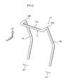
Fig. 2 is a perspective view illustrating a headrest stay of the headrest device ofFig. 1 ; -
Fig. 3 is a vertical cross-section corresponding toFig. 1 illustrating a state in which the head of an occupant is supported from a rear side by a support face of an internal structure; -
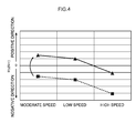
Fig. 4 is a graph illustrating relationships between collision speed in a rear-on collision and a bending moment (My) arising on the neck of an occupant; -
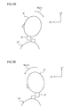
Fig. 5A is a schematic side view to explain a situation in which a bending moment on the neck of an occupant is negative; andFig. 5B is a schematic side view to explain a situation in which a bending moment on the neck of an occupant is positive. -
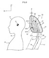
Fig. 6 is a vertical cross-section illustrating a configuration of a headrest device and members peripheral thereto according to a second exemplary embodiment of the present invention; and -
Fig. 7 is a vertical cross-section corresponding toFig. 6 and illustrating a state in which the head of an occupant is supported from the rear side by a support face of an internal structure. - Explanation follows regarding a
headrest device 10 according a first exemplary embodiment of the present invention with reference toFig. 1 to Fig. 5 . Note that in each of the drawings, an arrow FR indicates a vehicle front direction, an arrow UP indicates a vehicle upwards direction, an angle LH indicates a vehicle left hand direction, and an angle RH indicates a vehicle right hand direction as appropriate. Unless specifically indicated, when below explanation refers simply to the front-rear, up-down or left-right directions, these can be considered to be the front and rear in the vehicle front-rear direction, up and down in the vehicle up-down direction, and left and right in the vehicle left-right direction (the vehicle width direction). - As shown in
Fig. 1 , theheadrest device 10 of the present exemplary embodiment is attached at an upper end portion of aseatback 14 of avehicle seat 12. Theheadrest device 10 is configured by a headrest stay 16 serving as a framework member, aheadrest pad 18 that is a cushion member, acover 20 configuring a design face, and aninternal structure 22 serving as an impact absorption member. - Note that the
vehicle seat 12 is coupled to a vehicle body floor section, not shown in the drawings, such that anoccupant 24 sits facing the front. The front-rear, up-down and left-right directions of thevehicle seat 12 accordingly match the front-rear, up-down and left-right directions of the vehicle. - As shown in
Fig. 2 , theheadrest stay 16 is formed for example by bend-working metal piping, and is formed in an inverted substantially U shape as viewed along the front-rear direction. Theheadrest stay 16 is configured by a left and right pair ofleg portions 16L, and a connectingportion 16U that connects together upper end portions of the left andright leg portions 16L in the left-right direction. The left andright leg portions 16L are bent slightly in a vicinity of a top-bottom direction central portion as viewed from the side, as shown inFig. 1 . Upper end sides of the bent portions are inclined toward the front on progression toward an upper side. - As shown in
Fig. 1 , lower end sides of the left andright leg portions 16L (namely lower end sides of the headrest stay 16) are coupled to headrest supports 26 provided at an upper end portion of theseatback 14. The headrest supports 26 are mounted toheadrest support brackets 30 that are fixed to an upper end portion of aseatback frame 28 that serves as a framework member of theseatback 14. The lower end sides of theheadrest stay 16 are accordingly coupled to the upper end portion of theseatback frame 28 through the headrest supports 26 and theheadrest support brackets 30 so as to be height-adjustable. - The
headrest pad 18 is configured from a resilient foam material such as a urethane foam, and an upper end side of theheadrest stay 16 is embedded in theheadrest pad 18. Theheadrest pad 18 is accordingly supported by theheadrest stay 16. The surface of theheadrest pad 18 is covered by thecover 20 that is sewn into a bag shape from a material such as cloth, leather or synthetic leather. Note that in the present exemplary embodiment, the height of theheadrest pad 18 with respect to theseatback 14 and a reclining angle of the seatback 14 (an angle of inclination with respect to a seat cushion, not shown in the drawings) are adjusted such that a front face central portion of theheadrest pad 18 faces a central portion of a back of the head H of theoccupant 24 from the rear. - The
internal structure 22 is embedded inside theheadrest pad 18. Theinternal structure 22 is formed from a hard material such as a hard urethane foam in a substantially block shape that is smaller than theheadrest pad 18. Theinternal structure 22 is attached to the headrest stay 16 by for example fitting the left andright leg portions 16L of the headrest stay 16 into a left and right pair of vertical grooves formed on a rear face side of theinternal structure 22. Theinternal structure 22 is thus supported from the rear side by theheadrest stay 16. - The front face of the
internal structure 22 is formed with a curved face shape following afront face portion 20A of thecover 20. A portion of substantially uniform thickness of theheadrest pad 18 is interposed between the front face of theinternal structure 22 and thefront face portion 20A. Asupport face 22A provided at an upper portion side of the front face of theinternal structure 22 is disposed at a substantially equivalent height to the center of gravity G of the head H of theoccupant 24. The height of the center of gravity G is at substantially the same height as a rearmost end portion of the head H of theoccupant 24, namely the portion of the head H that protrudes furthest toward the rear. - Accordingly, as shown in
Fig. 3 , configuration is made such that when the vehicle is involved in a rear-on collision, theheadrest pad 18 is squashed under load from the head H of theoccupant 24 moving toward the rear under inertia, and a rear end portion of the head H is supported from the rear by thesupport face 22A of the internal structure 22 (the head H receives a reaction force toward the front from thesupport face 22A). - Note that during manufacture of the
headrest device 10, the upper end side of the headrest stay 16 to which theinternal structure 22 is attached is inserted inside thecover 20 and set in a mold, not shown in the drawings. Integral molding is performed in this state by injecting a foaming material for theheadrest pad 18 into thecover 20 and causing the material to foam and expand. - In the present exemplary embodiment, the upper end portions of the left and
right leg portions 16L of the headrest stay 16 are bent toward the front. Aforward projection portion 17 is formed thereby at the upper end portion of theheadrest stay 16. Theforward projection portion 17 is configured by portions of the left andright leg portions 16L and the connectingportion 16U. The portions of the left andright leg portions 16L extend further toward a connectingportion 16U side frombent portions 16B positioned at upper end portions of the left andright leg portions 16L,. Theforward projection portion 17 is formed in a substantially U-shape that is open toward the rear as viewed in plane view. Theforward projection portion 17 is configured by a portion of theheadrest stay 16, and is accordingly the same rigid body as theheadrest stay 16. - The
forward projection portion 17 described above is disposed further at an upper side than theinternal structure 22, and projects out toward the front (to thefront face portion 20A side). A front end portion of the forward projection portion 17 (thecoupling portion 16U) projects out slightly further to the front than the front end of thesupport face 22A. The position of the connectingportion 16U is configured such that a front end portion of the connectingportion 16U is at a position facing the head H that is supported by thesupport face 22A from the rear in the rear-on collision as described above. Namely, the front end portion of the connectingportion 16U is at a position that suppresses the head H supported by thesupport face 22A from tilting backward by pivoting about thesupport face 22A. Detailed explanation follows regarding setting the position (placement) of theforward projection portion 17. - During a rear-on collision, a bending moment (My) arises on a neck of the
occupant 24 due to the head H of theoccupant 24 tilting backward or tilting forward. The value of the bending moment (My) varies depending on the collision speed of the rear-on collision, and on differences in the vehicle seat structure. For example, the broken line inFig. 4 shows the bending moment (My) in a case for avehicle seat 12 of the present exemplary embodiment that however, does not have the upper end portion of the headrest stay 16 bent toward the front and that has theforward projection portion 17 omitted (referred to below as the Comparative Example). The moderate speed, low speed and high speed shown inFig. 4 illustrate differences in the collision speed in a rear-on collision. - As shown in
Fig. 4 , the bending moment (My) is unevenly distributed at a negative side in the Comparative Example. Note that as shown inFig. 5A , when the bending moment (My) is negative, the head H of theoccupant 24 is tilted backward so as to raise a chin (make the chin stick out). However, as shown inFig. 5B , when the bending moment (My) is positive, the head H of theoccupant 24 is tilted forward such that the chin is pulled in. - In other words, in the Comparative Example described above, the head H of the
occupant 24 tends to be tilted backward such that the chin is raised no matter whether the collision speed is a moderate speed, a high speed, or a low speed. Moreover, as shown inFig. 4 , in the Comparative Example described above, it is liable that bending moment (My) values increases in the sequence of moderate speed, low speed, and high speed. Protective performance for the neck N can be improved the closer the bending moment (My) is to zero. - In the
vehicle seat 12 according to the present exemplary embodiment, the position of theforward projection portion 17 is determined so as to make the bending moment (My) closer to zero in all three speeds of the above collision. For example the position in the up-down direction of theforward projection portion 17 is set at a position in a region of tens of mm higher that the center of gravity G of head H of theoccupant 24. Moreover, the position in the front-rear direction of the front end of theforward projection portion 17 is set at a position projecting out in a region of several mm further to the front than the front end of thesupport face 22A of the internal structure 22 (see arrows P inFig. 1 ). Note that, configuration is furthermore made such that when the head H of theoccupant 24 is supported by thesupport face 22A of the internal structure 22 (the state illustrated inFig. 3 ), the front end portion of theforward projection portion 17 is disposed in a region of several mm away from the head H. - Explanation follows regarding operation and advantageous effects of the present exemplary embodiment.
- In the
headrest device 10 configured as described above, when the vehicle is involved in a rear-on collision, theheadrest pad 18 is squashed under load from the head H of theoccupant 24 moving toward the rear under inertia, and the head H is supported from the rear by thesupport face 22A of theinternal structure 22. Theforward projection portion 17 provided to the upper end portion of theheadrest stay 16 is disposed at the upper side of thesupport face 22A, with the front end portion of theforward projection portion 17 facing the head H from the rear. Accordingly, when the head H that is supported by thesupport face 22A attempts to tilt backward by pivoting about thesupport face 22A, the backward tilt of the head H is suppressed due to theforward projection portion 17 supporting the head H further at the upper side than the center of gravity G of the head H. - Moreover, in the present exemplary embodiment, the front end portion of the
forward projection portion 17 of the headrest stay 16 projects out further toward the front than thesupport face 22A. Accordingly, as shown inFig. 3 , when the rear end portion of the head H is being supported by thesupport face 22A, the front end portion of theforward projection portion 17 can be placed in close proximity to and faces a portion of the head H further at the upper side than the rear end portion of the head H. Backward tilting of the head H pivoting about thesupport face 22A can accordingly be efficiently suppressed as a result. - Accordingly, since in the present exemplary embodiment, the head H can be suppressed from tilting backward due to pivoting about the
support face 22A, the bending moment (My) can be brought closer to zero for each of the moderate, low, and high collision speeds as shown by the solid line inFig. 4 . Protection performance for the neck N can be improved as a result. - Note that in the exemplary embodiment described above, explanation has been given regarding a case in which the present invention is applied to the Comparative Example (vehicle seat) in which the bending moment (My) is unevenly distributed at the negative side, however there is no limitation thereto. According to the present invention, the direction and strength of head tilting can be controlled by setting the position of the front end portion of the forward projection portion depending on the collision speed in a rear-on collision and on differences in the vehicle seat.
- In the second exemplary embodiment below, explanation is given to a case in which the present invention is applied to a vehicle seat in which the bending moment (My) is unevenly distributed at a positive side (namely, a vehicle seat in which the head of an occupant tends to be tilted forward so as to pull in the chin in a rear-on collision). Note that configuration and operation that is basically the same as that of the first exemplary embodiment is allocated the same reference numerals as in the first exemplary embodiment, and explanation thereof is omitted.
-
Fig. 6 is a vertical cross-section as viewed from the vehicle width direction outside, illustrating a configuration of aheadrest device 50 and members peripheral thereto according to the second exemplary embodiment of the present invention. The configuration of the present exemplary embodiment is basically the same as in the first exemplary embodiment, however theforward projection portion 17 of the first exemplary embodiment is omitted from a headrest stay 16' of the present exemplary embodiment. Namely, an upper end portion of the headrest stay 16' is not bent toward the front, and a connectingportion 16U is positioned to the rear from an upper end portion of aninternal structure 22. - Moreover, in the headrest stay 16', a
forward projection portion 52 that configures a portion of the headrest stay 16' is fixed at an up-down direction intermediate portion of left andright leg portions 16L. Theforward projection portion 52 is formed for example by bend-working metal piping, and is configured by a left and right pair offront extension portions 52A that extend toward the front from the up-down direction intermediate portion of the left andright leg portions 16L, and a connectingportion 52B that connects together front end portions of the left and rightfront extension portions 52A in the left-right direction. Rear end portions of the left and rightfront extension portions 52A are bent toward the lower side and are joined to the up-down direction intermediate portions of the left andright leg portions 16L by a method such as welding. Theforward projection portion 52 and the left andright leg portions 16L are thereby integrated together. Moreover, the connectingportion 52B, namely a front end portion of theforward projection portion 52, extends in the left-right direction along the front face of theinternal structure 22 at a lower side of asupport face 22A of the internal structure 22 (namely at the lower side of the center of gravity G of the head H). Thecoupling portion 52B also projects out slightly further toward the front (for example in a region of several mm) than thesupport face 22A (see the arrows P inFig. 6 ). - As shown in
Fig. 7 , in the present exemplary embodiment, when the vehicle is involved in a rear-on collision, aheadrest pad 18 is squashed under load from the head H of anoccupant 24 moving toward the rear under inertia, and the head H is supported from the rear by thesupport face 22A of theinternal structure 22. Theforward projection portion 52 that is provided to the up-down direction intermediate portions of the headrest stay 16' is disposed at the lower side of thesupport face 22A, with the front end portion of theforward projection portion 52 facing the head H from the rear. When the head H that is supported by thesupport face 22A attempts to tilt forward by pivoting about thesupport face 22A, the head H is accordingly supported by theforward projection portion 52 at the lower side of the center of gravity G of the head H, thereby suppressing the head H from tilting forward. - Moreover, in the present exemplary embodiment, the front end portion of the
forward projection portion 52 of the headrest stay 16' projects out further toward the front than thesupport face 22A. As shown inFig. 7 , when the rear end portion of the head H is being supported by thesupport face 22A, the front end portion of theforward projection portion 52 can be placed in close proximity to and faces a portion of the head H at the lower side of the rear end portion of the head H. Forward tilting of the head H due to pivoting about thesupport face 22A can be efficiently suppressed as a result. - Since in the present exemplary embodiment, the head H can thus be suppressed from tilting forward by pivoting about the
support face 22A, the bending moment (My) can be brought closer to zero for each of the moderate, low and high collision speeds. Protection performance for the neck N can be improved as a result. - Note that in each of the above exemplary embodiments, the front end portions of the
forward projection portions support face 22A of theinternal structure 22. However the present invention is not limited thereto, and configuration may be made wherein the front end portion of the forward projection portion is disposed further toward the rear than the support face of the internal structure. - Various other modifications may be implemented in the present invention within a scope not departing from the gist of the present invention. Moreover, the scope of the present invention is obviously not limited by each of the exemplary embodiments described above.
Claims (4)
- A headrest device comprising:a headrest stay that is coupled to an upper end portion of a seatback of a vehicle seat, and that supports a headrest pad;an internal structure that is embedded inside the headrest pad, that is supported from a rear by the headrest stay, and that supports a head of an occupant from the rear during a vehicle rear-on collision via a support face that is formed at a front face of the internal structure; anda forward projection portion that is configured by a portion of the headrest stay that projects forward, that is disposed at an upper side or a lower side of the support face within the headrest pad, and that suppresses the head supported by the support face from tilting backward or tilting forward by pivoting about the support face as a pivoting center.
- A headrest device of claim 1, wherein a front end portion of the forward projection portion is disposed so as to face, from the rear, the head that is supported by the support face.
- The headrest device of claim 1, wherein a front end portion of the forward projection portion projects out further forward than the support face of the internal structure.
- The headrest device of claim 2, wherein the front end portion of the forward projection portion projects out further forward than the support face of the internal structure.
Applications Claiming Priority (1)
| Application Number | Priority Date | Filing Date | Title |
|---|---|---|---|
| JP2012097935A JP5925575B2 (en) | 2012-04-23 | 2012-04-23 | Headrest device |
Publications (2)
| Publication Number | Publication Date |
|---|---|
| EP2657073A1 true EP2657073A1 (en) | 2013-10-30 |
| EP2657073B1 EP2657073B1 (en) | 2014-10-22 |
Family
ID=48182741
Family Applications (1)
| Application Number | Title | Priority Date | Filing Date |
|---|---|---|---|
| EP13164405.6A Not-in-force EP2657073B1 (en) | 2012-04-23 | 2013-04-19 | Headrest device |
Country Status (5)
| Country | Link |
|---|---|
| US (1) | US9403451B2 (en) |
| EP (1) | EP2657073B1 (en) |
| JP (1) | JP5925575B2 (en) |
| KR (1) | KR20130119874A (en) |
| CN (1) | CN103373258B (en) |
Families Citing this family (11)
| Publication number | Priority date | Publication date | Assignee | Title |
|---|---|---|---|---|
| US9511695B2 (en) * | 2011-09-25 | 2016-12-06 | Ts Tech Co., Ltd. | Vehicle seat device |
| KR101389067B1 (en) * | 2012-05-02 | 2014-04-23 | 경북대학교 산학협력단 | safety belt system for vehicle |
| JP6208070B2 (en) * | 2014-04-25 | 2017-10-04 | トヨタ紡織株式会社 | Vehicle seat |
| WO2016049691A1 (en) * | 2014-09-30 | 2016-04-07 | Cj Albert Builders Pty Ltd | Head and neck rest |
| FR3055829B1 (en) * | 2016-09-09 | 2018-09-28 | Faurecia Sieges Dautomobile | INTEGRATION OF A DEVICE IN A SEAT ELEMENT FOR A MOTOR VEHICLE |
| US10835063B2 (en) * | 2017-06-27 | 2020-11-17 | Bryan Bourgeois | Headrest cushion assembly for neck pain |
| JP7003872B2 (en) * | 2018-08-07 | 2022-01-21 | トヨタ自動車株式会社 | Vehicle seat |
| CN112805179B (en) * | 2018-10-09 | 2023-08-01 | 提爱思科技股份有限公司 | Vehicle seat |
| JP7271161B2 (en) * | 2018-12-19 | 2023-05-11 | 株式会社タチエス | Headrests and vehicle seats |
| WO2020201842A1 (en) * | 2019-04-02 | 2020-10-08 | Gestind S.P.A. | A vehicle seat |
| US11173820B2 (en) * | 2020-01-14 | 2021-11-16 | Honda Motor Co., Ltd. | Headrest, vehicle seat and vehicle |
Citations (6)
| Publication number | Priority date | Publication date | Assignee | Title |
|---|---|---|---|---|
| US3205005A (en) * | 1964-08-10 | 1965-09-07 | Brown Ray | Energy-absorbing headrest for motor vehicle seats |
| JP2006006823A (en) * | 2004-06-29 | 2006-01-12 | Inoac Corp | Headrest backing and headrest |
| DE102005030313A1 (en) * | 2005-06-23 | 2006-12-28 | Volkswagen Ag | Headrest for vehicle seat e.g. for backrest of motor vehicle seat which can be brought into contact with head of vehicle occupant at two different heights to reduce or neutralize torque about y-axis |
| US20090200843A1 (en) * | 2008-02-13 | 2009-08-13 | Tachi-S Co., Ltd. | Headrest for vehicle seat |
| KR20090092581A (en) * | 2008-02-27 | 2009-09-01 | 주식회사다스 | Headrest for vehicle |
| GB2498430A (en) * | 2012-01-12 | 2013-07-17 | Gm Global Tech Operations Inc | Head restraint for a vehicle seat |
Family Cites Families (38)
| Publication number | Priority date | Publication date | Assignee | Title |
|---|---|---|---|---|
| US3366417A (en) * | 1966-08-08 | 1968-01-30 | Earl H. Belk | Headrest assembly for vehicle seat back |
| DE1780300C3 (en) * | 1968-08-28 | 1979-01-25 | Recaro Gmbh & Co, 7000 Stuttgart | Headrest for automobile seats |
| US5139310A (en) * | 1991-04-16 | 1992-08-18 | Tachi-S Co., Ltd. | Headrest |
| US5645320A (en) * | 1996-01-22 | 1997-07-08 | Jones; Ronald | Headrest support for vehicle seat |
| DE10005817B4 (en) * | 2000-02-10 | 2004-06-09 | Itw-Ateco Gmbh | Mechanical headrest retraction with memory function |
| DE10012973B4 (en) * | 2000-03-16 | 2004-02-26 | Daimlerchrysler Ag | Headrest for a vehicle seat |
| DE20110342U1 (en) * | 2001-06-22 | 2002-10-24 | Johnson Controls GmbH, 51399 Burscheid | Headrest arrangement for a vehicle seat and vehicle seat equipped therewith, in particular an emergency seat |
| US7537282B2 (en) * | 2003-12-16 | 2009-05-26 | Lear Corporation | Head restraint arrangement for a vehicle seat and a method of manufacture |
| US7059681B2 (en) * | 2004-01-29 | 2006-06-13 | Tachi-S Co., Ltd. | Headrest for vehicle seat |
| US7618091B2 (en) * | 2004-01-30 | 2009-11-17 | Toyota Boshoku Kabushiki Kaisha | Head rest control device and active head rest |
| JP4647331B2 (en) * | 2004-03-23 | 2011-03-09 | 株式会社東洋シート | Vehicle seat with headrest |
| JP4490213B2 (en) * | 2004-08-31 | 2010-06-23 | 株式会社イノアックコーポレーション | Headrest |
| JP4690085B2 (en) * | 2005-03-23 | 2011-06-01 | アイシン精機株式会社 | Headrest |
| US7152928B2 (en) * | 2005-04-20 | 2006-12-26 | Lear Corporation | Head restraint assembly for a vehicle seat assembly |
| JP2007195768A (en) * | 2006-01-27 | 2007-08-09 | Tachi S Co Ltd | Integrated foam with outer skin |
| US7517009B2 (en) * | 2006-09-06 | 2009-04-14 | Lear Corporation | Dual release headrest |
| JP4253674B2 (en) * | 2006-10-05 | 2009-04-15 | 有限会社オダ技商 | Plastic headrest frame |
| US20080100116A1 (en) * | 2006-10-27 | 2008-05-01 | Ford Global Technologies, Llc | Head restraint |
| EP2116149B1 (en) * | 2007-02-05 | 2013-05-22 | TS Tech Co., Ltd. | Headrest and vehicle seat with the headrest |
| JP5252824B2 (en) * | 2007-03-31 | 2013-07-31 | テイ・エス テック株式会社 | Headrest and vehicle seat provided with the headrest |
| US20080265645A1 (en) * | 2007-04-24 | 2008-10-30 | Tachi-S Co., Ltd. | Headrest |
| DE102007033604B3 (en) * | 2007-07-17 | 2009-01-22 | Muhr Und Bender Kg | Head rest carrying element |
| JP5592071B2 (en) * | 2008-01-11 | 2014-09-17 | テイ・エス テック株式会社 | Headrest support structure |
| DE102008029617B4 (en) * | 2008-06-23 | 2013-05-23 | Lear Corp. | Vehicle seat assembly with an energy absorption device |
| US20100078983A1 (en) * | 2008-10-01 | 2010-04-01 | Lear Corporation | Support member for vehicle seat head restraint |
| DE102009019439B3 (en) * | 2008-11-10 | 2010-06-24 | Grammer Ag | Headrest for vehicle seats |
| CN102596637B (en) * | 2009-10-29 | 2014-06-04 | 丰田自动车株式会社 | Headrest stay and active headrest |
| US8182042B2 (en) * | 2010-02-03 | 2012-05-22 | Honda Motor Co., Ltd. | Adjustable vehicle head restraint assembly |
| JP5513203B2 (en) * | 2010-03-29 | 2014-06-04 | 日本発條株式会社 | Headrest device |
| JP5578961B2 (en) * | 2010-06-24 | 2014-08-27 | 日本発條株式会社 | Headrest device, headrest position adjusting method, and vehicle seat |
| JP5154613B2 (en) * | 2010-08-05 | 2013-02-27 | 日本発條株式会社 | Headrest device, headrest position adjusting method, and vehicle seat |
| US8657378B2 (en) * | 2010-10-04 | 2014-02-25 | Lear Corporation | Seat assembly having an adjustable head restraint assembly |
| JP5617522B2 (en) * | 2010-10-21 | 2014-11-05 | トヨタ紡織株式会社 | Vehicle seat |
| DE102011005590B4 (en) * | 2011-03-16 | 2013-05-16 | Lear Corporation | Seat assembly with a movable headrest assembly |
| DE102011100341B4 (en) * | 2011-04-14 | 2016-12-01 | Grammer Aktiengesellschaft | Headrest for vehicle seats and method for producing a headrest for vehicle seats |
| CN202147607U (en) * | 2011-07-27 | 2012-02-22 | 长春博林汽车技术有限公司 | Vehicular anti-flogging headrest |
| US8746800B2 (en) * | 2011-08-23 | 2014-06-10 | Honda Motor Co., Ltd. | Vehicle head restraint assembly |
| US9278635B2 (en) * | 2013-01-30 | 2016-03-08 | Lear Corporation | Adjustable head restraint assembly |
-
2012
- 2012-04-23 JP JP2012097935A patent/JP5925575B2/en not_active Expired - Fee Related
-
2013
- 2013-04-19 EP EP13164405.6A patent/EP2657073B1/en not_active Not-in-force
- 2013-04-22 CN CN201310141417.5A patent/CN103373258B/en not_active Expired - Fee Related
- 2013-04-22 US US13/867,949 patent/US9403451B2/en active Active
- 2013-04-22 KR KR1020130044206A patent/KR20130119874A/en not_active Ceased
Patent Citations (7)
| Publication number | Priority date | Publication date | Assignee | Title |
|---|---|---|---|---|
| US3205005A (en) * | 1964-08-10 | 1965-09-07 | Brown Ray | Energy-absorbing headrest for motor vehicle seats |
| JP2006006823A (en) * | 2004-06-29 | 2006-01-12 | Inoac Corp | Headrest backing and headrest |
| JP4431449B2 (en) | 2004-06-29 | 2010-03-17 | 株式会社イノアックコーポレーション | Headrest base material and headrest |
| DE102005030313A1 (en) * | 2005-06-23 | 2006-12-28 | Volkswagen Ag | Headrest for vehicle seat e.g. for backrest of motor vehicle seat which can be brought into contact with head of vehicle occupant at two different heights to reduce or neutralize torque about y-axis |
| US20090200843A1 (en) * | 2008-02-13 | 2009-08-13 | Tachi-S Co., Ltd. | Headrest for vehicle seat |
| KR20090092581A (en) * | 2008-02-27 | 2009-09-01 | 주식회사다스 | Headrest for vehicle |
| GB2498430A (en) * | 2012-01-12 | 2013-07-17 | Gm Global Tech Operations Inc | Head restraint for a vehicle seat |
Also Published As
| Publication number | Publication date |
|---|---|
| US20130300166A1 (en) | 2013-11-14 |
| CN103373258B (en) | 2016-10-05 |
| US9403451B2 (en) | 2016-08-02 |
| JP2013224112A (en) | 2013-10-31 |
| KR20130119874A (en) | 2013-11-01 |
| EP2657073B1 (en) | 2014-10-22 |
| CN103373258A (en) | 2013-10-30 |
| JP5925575B2 (en) | 2016-05-25 |
Similar Documents
| Publication | Publication Date | Title |
|---|---|---|
| EP2657073B1 (en) | Headrest device | |
| US10093202B2 (en) | Seatback frame | |
| KR20200142448A (en) | Neck supporting pillow of headrest for chair | |
| US20150291070A1 (en) | Vehicle seat | |
| CN105599655A (en) | Vehicle seat | |
| JP6438210B2 (en) | Vehicle seat | |
| WO2020255754A1 (en) | Vehicle seat | |
| US8919877B2 (en) | Head restraint for a vehicle seat | |
| JP6053657B2 (en) | Neck support device for vehicle seat | |
| JP2025183776A (en) | Vehicle seats | |
| JP2014043160A (en) | Vehicle seat | |
| JP4417220B2 (en) | Vehicle seat | |
| JP6070433B2 (en) | Vehicle seat | |
| JP7714495B2 (en) | Vehicle seats | |
| JP7712534B2 (en) | Vehicle seats | |
| JP2015209101A (en) | Vehicle seat | |
| JP2010083268A (en) | Seat for vehicle | |
| JP7838296B2 (en) | Vehicle seat back | |
| JP6064922B2 (en) | Vehicle seat device | |
| CN118665301A (en) | Chair seat | |
| JP2022066360A (en) | Vehicle seat | |
| JP6200037B2 (en) | Vehicle seat | |
| JP2024165087A (en) | Headrest and vehicle seat | |
| JP2025113746A (en) | Vehicle seats | |
| CN103180173A (en) | Vehicle seat comprising a head restraint |
Legal Events
| Date | Code | Title | Description |
|---|---|---|---|
| PUAI | Public reference made under article 153(3) epc to a published international application that has entered the european phase |
Free format text: ORIGINAL CODE: 0009012 |
|
| AK | Designated contracting states |
Kind code of ref document: A1 Designated state(s): AL AT BE BG CH CY CZ DE DK EE ES FI FR GB GR HR HU IE IS IT LI LT LU LV MC MK MT NL NO PL PT RO RS SE SI SK SM TR |
|
| AX | Request for extension of the european patent |
Extension state: BA ME |
|
| 17P | Request for examination filed |
Effective date: 20140415 |
|
| RBV | Designated contracting states (corrected) |
Designated state(s): AL AT BE BG CH CY CZ DE DK EE ES FI FR GB GR HR HU IE IS IT LI LT LU LV MC MK MT NL NO PL PT RO RS SE SI SK SM TR |
|
| GRAP | Despatch of communication of intention to grant a patent |
Free format text: ORIGINAL CODE: EPIDOSNIGR1 |
|
| RIC1 | Information provided on ipc code assigned before grant |
Ipc: B60N 2/42 20060101ALI20140513BHEP Ipc: B60N 2/48 20060101AFI20140513BHEP |
|
| INTG | Intention to grant announced |
Effective date: 20140612 |
|
| GRAS | Grant fee paid |
Free format text: ORIGINAL CODE: EPIDOSNIGR3 |
|
| GRAA | (expected) grant |
Free format text: ORIGINAL CODE: 0009210 |
|
| AK | Designated contracting states |
Kind code of ref document: B1 Designated state(s): AL AT BE BG CH CY CZ DE DK EE ES FI FR GB GR HR HU IE IS IT LI LT LU LV MC MK MT NL NO PL PT RO RS SE SI SK SM TR |
|
| REG | Reference to a national code |
Ref country code: GB Ref legal event code: FG4D |
|
| REG | Reference to a national code |
Ref country code: CH Ref legal event code: EP |
|
| REG | Reference to a national code |
Ref country code: AT Ref legal event code: REF Ref document number: 692457 Country of ref document: AT Kind code of ref document: T Effective date: 20141115 |
|
| REG | Reference to a national code |
Ref country code: IE Ref legal event code: FG4D |
|
| REG | Reference to a national code |
Ref country code: DE Ref legal event code: R096 Ref document number: 602013000374 Country of ref document: DE Effective date: 20141204 |
|
| REG | Reference to a national code |
Ref country code: NL Ref legal event code: VDEP Effective date: 20141022 |
|
| REG | Reference to a national code |
Ref country code: AT Ref legal event code: MK05 Ref document number: 692457 Country of ref document: AT Kind code of ref document: T Effective date: 20141022 |
|
| REG | Reference to a national code |
Ref country code: LT Ref legal event code: MG4D |
|
| PG25 | Lapsed in a contracting state [announced via postgrant information from national office to epo] |
Ref country code: PT Free format text: LAPSE BECAUSE OF FAILURE TO SUBMIT A TRANSLATION OF THE DESCRIPTION OR TO PAY THE FEE WITHIN THE PRESCRIBED TIME-LIMIT Effective date: 20150223 Ref country code: NO Free format text: LAPSE BECAUSE OF FAILURE TO SUBMIT A TRANSLATION OF THE DESCRIPTION OR TO PAY THE FEE WITHIN THE PRESCRIBED TIME-LIMIT Effective date: 20150122 Ref country code: IS Free format text: LAPSE BECAUSE OF FAILURE TO SUBMIT A TRANSLATION OF THE DESCRIPTION OR TO PAY THE FEE WITHIN THE PRESCRIBED TIME-LIMIT Effective date: 20150222 Ref country code: NL Free format text: LAPSE BECAUSE OF FAILURE TO SUBMIT A TRANSLATION OF THE DESCRIPTION OR TO PAY THE FEE WITHIN THE PRESCRIBED TIME-LIMIT Effective date: 20141022 Ref country code: FI Free format text: LAPSE BECAUSE OF FAILURE TO SUBMIT A TRANSLATION OF THE DESCRIPTION OR TO PAY THE FEE WITHIN THE PRESCRIBED TIME-LIMIT Effective date: 20141022 Ref country code: LT Free format text: LAPSE BECAUSE OF FAILURE TO SUBMIT A TRANSLATION OF THE DESCRIPTION OR TO PAY THE FEE WITHIN THE PRESCRIBED TIME-LIMIT Effective date: 20141022 Ref country code: ES Free format text: LAPSE BECAUSE OF FAILURE TO SUBMIT A TRANSLATION OF THE DESCRIPTION OR TO PAY THE FEE WITHIN THE PRESCRIBED TIME-LIMIT Effective date: 20141022 |
|
| PG25 | Lapsed in a contracting state [announced via postgrant information from national office to epo] |
Ref country code: LV Free format text: LAPSE BECAUSE OF FAILURE TO SUBMIT A TRANSLATION OF THE DESCRIPTION OR TO PAY THE FEE WITHIN THE PRESCRIBED TIME-LIMIT Effective date: 20141022 Ref country code: GR Free format text: LAPSE BECAUSE OF FAILURE TO SUBMIT A TRANSLATION OF THE DESCRIPTION OR TO PAY THE FEE WITHIN THE PRESCRIBED TIME-LIMIT Effective date: 20150123 Ref country code: HR Free format text: LAPSE BECAUSE OF FAILURE TO SUBMIT A TRANSLATION OF THE DESCRIPTION OR TO PAY THE FEE WITHIN THE PRESCRIBED TIME-LIMIT Effective date: 20141022 Ref country code: PL Free format text: LAPSE BECAUSE OF FAILURE TO SUBMIT A TRANSLATION OF THE DESCRIPTION OR TO PAY THE FEE WITHIN THE PRESCRIBED TIME-LIMIT Effective date: 20141022 Ref country code: CY Free format text: LAPSE BECAUSE OF FAILURE TO SUBMIT A TRANSLATION OF THE DESCRIPTION OR TO PAY THE FEE WITHIN THE PRESCRIBED TIME-LIMIT Effective date: 20141022 Ref country code: RS Free format text: LAPSE BECAUSE OF FAILURE TO SUBMIT A TRANSLATION OF THE DESCRIPTION OR TO PAY THE FEE WITHIN THE PRESCRIBED TIME-LIMIT Effective date: 20141022 Ref country code: AT Free format text: LAPSE BECAUSE OF FAILURE TO SUBMIT A TRANSLATION OF THE DESCRIPTION OR TO PAY THE FEE WITHIN THE PRESCRIBED TIME-LIMIT Effective date: 20141022 Ref country code: SE Free format text: LAPSE BECAUSE OF FAILURE TO SUBMIT A TRANSLATION OF THE DESCRIPTION OR TO PAY THE FEE WITHIN THE PRESCRIBED TIME-LIMIT Effective date: 20141022 |
|
| REG | Reference to a national code |
Ref country code: DE Ref legal event code: R097 Ref document number: 602013000374 Country of ref document: DE |
|
| PG25 | Lapsed in a contracting state [announced via postgrant information from national office to epo] |
Ref country code: CZ Free format text: LAPSE BECAUSE OF FAILURE TO SUBMIT A TRANSLATION OF THE DESCRIPTION OR TO PAY THE FEE WITHIN THE PRESCRIBED TIME-LIMIT Effective date: 20141022 Ref country code: RO Free format text: LAPSE BECAUSE OF FAILURE TO SUBMIT A TRANSLATION OF THE DESCRIPTION OR TO PAY THE FEE WITHIN THE PRESCRIBED TIME-LIMIT Effective date: 20141022 Ref country code: SK Free format text: LAPSE BECAUSE OF FAILURE TO SUBMIT A TRANSLATION OF THE DESCRIPTION OR TO PAY THE FEE WITHIN THE PRESCRIBED TIME-LIMIT Effective date: 20141022 Ref country code: EE Free format text: LAPSE BECAUSE OF FAILURE TO SUBMIT A TRANSLATION OF THE DESCRIPTION OR TO PAY THE FEE WITHIN THE PRESCRIBED TIME-LIMIT Effective date: 20141022 Ref country code: DK Free format text: LAPSE BECAUSE OF FAILURE TO SUBMIT A TRANSLATION OF THE DESCRIPTION OR TO PAY THE FEE WITHIN THE PRESCRIBED TIME-LIMIT Effective date: 20141022 |
|
| PLBE | No opposition filed within time limit |
Free format text: ORIGINAL CODE: 0009261 |
|
| STAA | Information on the status of an ep patent application or granted ep patent |
Free format text: STATUS: NO OPPOSITION FILED WITHIN TIME LIMIT |
|
| PG25 | Lapsed in a contracting state [announced via postgrant information from national office to epo] |
Ref country code: IT Free format text: LAPSE BECAUSE OF FAILURE TO SUBMIT A TRANSLATION OF THE DESCRIPTION OR TO PAY THE FEE WITHIN THE PRESCRIBED TIME-LIMIT Effective date: 20141022 |
|
| 26N | No opposition filed |
Effective date: 20150723 |
|
| PG25 | Lapsed in a contracting state [announced via postgrant information from national office to epo] |
Ref country code: MC Free format text: LAPSE BECAUSE OF FAILURE TO SUBMIT A TRANSLATION OF THE DESCRIPTION OR TO PAY THE FEE WITHIN THE PRESCRIBED TIME-LIMIT Effective date: 20141022 Ref country code: LU Free format text: LAPSE BECAUSE OF FAILURE TO SUBMIT A TRANSLATION OF THE DESCRIPTION OR TO PAY THE FEE WITHIN THE PRESCRIBED TIME-LIMIT Effective date: 20150419 |
|
| REG | Reference to a national code |
Ref country code: IE Ref legal event code: MM4A |
|
| REG | Reference to a national code |
Ref country code: FR Ref legal event code: ST Effective date: 20151231 |
|
| PG25 | Lapsed in a contracting state [announced via postgrant information from national office to epo] |
Ref country code: FR Free format text: LAPSE BECAUSE OF NON-PAYMENT OF DUE FEES Effective date: 20150430 Ref country code: SI Free format text: LAPSE BECAUSE OF FAILURE TO SUBMIT A TRANSLATION OF THE DESCRIPTION OR TO PAY THE FEE WITHIN THE PRESCRIBED TIME-LIMIT Effective date: 20141022 |
|
| PG25 | Lapsed in a contracting state [announced via postgrant information from national office to epo] |
Ref country code: IE Free format text: LAPSE BECAUSE OF NON-PAYMENT OF DUE FEES Effective date: 20150419 |
|
| REG | Reference to a national code |
Ref country code: CH Ref legal event code: PL |
|
| PG25 | Lapsed in a contracting state [announced via postgrant information from national office to epo] |
Ref country code: MT Free format text: LAPSE BECAUSE OF FAILURE TO SUBMIT A TRANSLATION OF THE DESCRIPTION OR TO PAY THE FEE WITHIN THE PRESCRIBED TIME-LIMIT Effective date: 20141022 |
|
| PG25 | Lapsed in a contracting state [announced via postgrant information from national office to epo] |
Ref country code: LI Free format text: LAPSE BECAUSE OF NON-PAYMENT OF DUE FEES Effective date: 20160430 Ref country code: CH Free format text: LAPSE BECAUSE OF NON-PAYMENT OF DUE FEES Effective date: 20160430 |
|
| PG25 | Lapsed in a contracting state [announced via postgrant information from national office to epo] |
Ref country code: HU Free format text: LAPSE BECAUSE OF FAILURE TO SUBMIT A TRANSLATION OF THE DESCRIPTION OR TO PAY THE FEE WITHIN THE PRESCRIBED TIME-LIMIT; INVALID AB INITIO Effective date: 20130419 Ref country code: BG Free format text: LAPSE BECAUSE OF FAILURE TO SUBMIT A TRANSLATION OF THE DESCRIPTION OR TO PAY THE FEE WITHIN THE PRESCRIBED TIME-LIMIT Effective date: 20141022 |
|
| PG25 | Lapsed in a contracting state [announced via postgrant information from national office to epo] |
Ref country code: TR Free format text: LAPSE BECAUSE OF FAILURE TO SUBMIT A TRANSLATION OF THE DESCRIPTION OR TO PAY THE FEE WITHIN THE PRESCRIBED TIME-LIMIT Effective date: 20141022 |
|
| PG25 | Lapsed in a contracting state [announced via postgrant information from national office to epo] |
Ref country code: BE Free format text: LAPSE BECAUSE OF FAILURE TO SUBMIT A TRANSLATION OF THE DESCRIPTION OR TO PAY THE FEE WITHIN THE PRESCRIBED TIME-LIMIT Effective date: 20141022 |
|
| REG | Reference to a national code |
Ref country code: DE Ref legal event code: R079 Ref document number: 602013000374 Country of ref document: DE Free format text: PREVIOUS MAIN CLASS: B60N0002480000 Ipc: B60N0002800000 |
|
| GBPC | Gb: european patent ceased through non-payment of renewal fee |
Effective date: 20170419 |
|
| PG25 | Lapsed in a contracting state [announced via postgrant information from national office to epo] |
Ref country code: GB Free format text: LAPSE BECAUSE OF NON-PAYMENT OF DUE FEES Effective date: 20170419 |
|
| PG25 | Lapsed in a contracting state [announced via postgrant information from national office to epo] |
Ref country code: SM Free format text: LAPSE BECAUSE OF FAILURE TO SUBMIT A TRANSLATION OF THE DESCRIPTION OR TO PAY THE FEE WITHIN THE PRESCRIBED TIME-LIMIT Effective date: 20141022 |
|
| PG25 | Lapsed in a contracting state [announced via postgrant information from national office to epo] |
Ref country code: MK Free format text: LAPSE BECAUSE OF FAILURE TO SUBMIT A TRANSLATION OF THE DESCRIPTION OR TO PAY THE FEE WITHIN THE PRESCRIBED TIME-LIMIT Effective date: 20141022 |
|
| PGFP | Annual fee paid to national office [announced via postgrant information from national office to epo] |
Ref country code: DE Payment date: 20180404 Year of fee payment: 6 |
|
| PG25 | Lapsed in a contracting state [announced via postgrant information from national office to epo] |
Ref country code: AL Free format text: LAPSE BECAUSE OF FAILURE TO SUBMIT A TRANSLATION OF THE DESCRIPTION OR TO PAY THE FEE WITHIN THE PRESCRIBED TIME-LIMIT Effective date: 20141022 |
|
| REG | Reference to a national code |
Ref country code: DE Ref legal event code: R119 Ref document number: 602013000374 Country of ref document: DE |
|
| PG25 | Lapsed in a contracting state [announced via postgrant information from national office to epo] |
Ref country code: DE Free format text: LAPSE BECAUSE OF NON-PAYMENT OF DUE FEES Effective date: 20191101 |