US9278635B2 - Adjustable head restraint assembly - Google Patents
Adjustable head restraint assembly Download PDFInfo
- Publication number
- US9278635B2 US9278635B2 US14/159,112 US201414159112A US9278635B2 US 9278635 B2 US9278635 B2 US 9278635B2 US 201414159112 A US201414159112 A US 201414159112A US 9278635 B2 US9278635 B2 US 9278635B2
- Authority
- US
- United States
- Prior art keywords
- guide member
- head restraint
- restraint assembly
- pair
- frame
- Prior art date
- Legal status (The legal status is an assumption and is not a legal conclusion. Google has not performed a legal analysis and makes no representation as to the accuracy of the status listed.)
- Active, expires
Links
Images


Classifications
-
- B60N2/4864—
-
- B—PERFORMING OPERATIONS; TRANSPORTING
- B60—VEHICLES IN GENERAL
- B60N—SEATS SPECIALLY ADAPTED FOR VEHICLES; VEHICLE PASSENGER ACCOMMODATION NOT OTHERWISE PROVIDED FOR
- B60N2/00—Seats specially adapted for vehicles; Arrangement or mounting of seats in vehicles
- B60N2/80—Head-rests
- B60N2/806—Head-rests movable or adjustable
- B60N2/865—Head-rests movable or adjustable providing a fore-and-aft movement with respect to the occupant's head
-
- B60N2/4811—
-
- B60N2/4814—
-
- B60N2/4817—
-
- B60N2/485—
-
- B—PERFORMING OPERATIONS; TRANSPORTING
- B60—VEHICLES IN GENERAL
- B60N—SEATS SPECIALLY ADAPTED FOR VEHICLES; VEHICLE PASSENGER ACCOMMODATION NOT OTHERWISE PROVIDED FOR
- B60N2/00—Seats specially adapted for vehicles; Arrangement or mounting of seats in vehicles
- B60N2/80—Head-rests
- B60N2/806—Head-rests movable or adjustable
- B60N2/809—Head-rests movable or adjustable vertically slidable
- B60N2/812—Head-rests movable or adjustable vertically slidable characterised by their locking devices
- B60N2/815—Release mechanisms, e.g. buttons
-
- B—PERFORMING OPERATIONS; TRANSPORTING
- B60—VEHICLES IN GENERAL
- B60N—SEATS SPECIALLY ADAPTED FOR VEHICLES; VEHICLE PASSENGER ACCOMMODATION NOT OTHERWISE PROVIDED FOR
- B60N2/00—Seats specially adapted for vehicles; Arrangement or mounting of seats in vehicles
- B60N2/80—Head-rests
- B60N2/806—Head-rests movable or adjustable
- B60N2/809—Head-rests movable or adjustable vertically slidable
- B60N2/812—Head-rests movable or adjustable vertically slidable characterised by their locking devices
- B60N2/818—Head-rests movable or adjustable vertically slidable characterised by their locking devices with stepwise positioning
-
- B—PERFORMING OPERATIONS; TRANSPORTING
- B60—VEHICLES IN GENERAL
- B60N—SEATS SPECIALLY ADAPTED FOR VEHICLES; VEHICLE PASSENGER ACCOMMODATION NOT OTHERWISE PROVIDED FOR
- B60N2/00—Seats specially adapted for vehicles; Arrangement or mounting of seats in vehicles
- B60N2/80—Head-rests
- B60N2/806—Head-rests movable or adjustable
- B60N2/838—Tiltable
- B60N2/841—Tiltable characterised by their locking devices
- B60N2/85—Tiltable characterised by their locking devices with continuous positioning
Definitions
- Embodiments relate to adjustable head restraint assemblies.
- a head restraint assembly is provided with a first guide member mounted proximate to a vehicle seat back.
- a second guide member is mounted to the first guide member for translation along the first guide member.
- a locking mechanism is mounted to the second guide member in cooperation with the first guide member for locking the second guide member relative to the first guide member.
- the first and second guide members are connected by at least one spherical bushing.
- a head restraint assembly is provided with a first guide member mounted proximate to a vehicle seat back.
- a second guide member is mounted to the first guide member for translation along the first guide member.
- a torsion spring is connected to the first guide member and oriented about the second guide member for locking the second guide member relative to the first guide member.
- At least one spherical bushing is mounted about the second guide member and received within the first guide member.
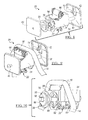
- FIG. 1 is a side elevation view of an adjustable head restraint assembly according to an embodiment
- FIG. 3 is a partial front perspective view of the head restraint assembly of FIG. 1 ;
- FIG. 4 is a partial rear perspective view of the head restraint assembly of FIG. 1 ;
- FIG. 6 is an exploded perspective view of the locking mechanism of FIG. 2 ;
- FIG. 8 is a partially exploded perspective view of the head restraint of FIG. 1 ;
- FIG. 11 is a partially exploded side view of the guide assembly of FIG. 2 ;
- FIG. 12 is a side view of the guide assembly of FIG. 2 ;
- FIG. 13 is a schematic view of the guide assembly of FIG. 2 , illustrated in alignment.
- FIG. 14 is another schematic view of the guide assembly of FIG. 2 , illustrated in misalignment.
- the support post 14 maybe fixed relative to the vehicle or the vehicle seat back.
- the support post 14 may be received within a guide sleeve for upright adjustment relative to the seatback.
- the support post 14 may have any suitable configuration.
- one or more support posts 14 may extend from the head restraint 12 .
- the support post 14 may be formed integrally with another support post 14 with a crossbar 16 interconnecting and spacing apart the support posts 14 .
- the support posts 14 may be made of any suitable material or materials such as a metal or metal alloy.
- the head restraint 12 may include a trim cover (not shown) for enclosing foam (also not shown), a housing 18 , and a locking mechanism 20 .
- a manual button assembly 22 extends from the housing 18 in the trim cover for manual actuation for disengaging the locking mechanism 20 .
- the button assembly 22 is illustrated oriented to be manually actuated by being pressed in a lateral direction of the head restraint 12 . Pressing the button assembly 22 releases the locking mechanism 20 and permits movement of the head restraint 12 relative to the support posts 14 in a fore and aft direction, which may be horizontal. In FIGS. 1-4 , the head restraint 12 is illustrated at a limit in one direction, the aft direction, relative to the vehicle. Thus, by depressing the button assembly 22 , the occupant may move the head restraint 12 in the fore direction from the position depicted, or to multiple, non-incremental positions therebetween.
- a frame 24 is mounted to the crossbar 16 for supporting the head restraint 12 .
- the frame 24 supports a pair of nuts 26 , 28 , ( FIGS. 1 , 2 , 4 - 6 and 8 - 14 ) which are each threaded into the frame 24 .
- the nuts 26 , 28 each retain a bushing 30 , 32 ( FIGS. 2 , 5 , 6 , and 9 - 14 ) with the locking mechanism 20 oriented therebetween.
- the housing 18 includes a pair of shells 34 , 36 , which are sized to mate and retain the components of the head restraint 12 therein.
- the upper shell 36 is illustrated removed in FIGS. 3 and 4 . Both shells are illustrated removed in FIGS. 5-12 .
- a guide shaft 38 extends in a fore and aft direction of the head restraint 12 .
- the guide shaft 38 is mounted to the shells 34 , 36 by a pair of brackets 40 , 42 , which are retained within the shells 34 , 36 .
- a through bolt 44 extends through the upper shell 36 , the bracket 40 , the nut 26 and bushing 30 , the locking mechanism 20 , the nut 28 and bushing 32 , the bracket 42 , the upper shell 36 again, and a nut 46 .
- the guide shaft 38 cooperates with the bushings 30 , 32 for translation of the guide shaft 38 , and consequently the head restraint 12 , relative to the bushings 30 , 32 and the support posts 14 for adjustment of the head restraint 12 relative to the support posts 14 .
- the button assembly 22 ( FIGS. 1 and 3 ) includes a bezel 54 mounted to the shells 34 , 36 .
- a button 56 is mounted in the bezel 54 for linear translation, which pivots a lever 58 ( FIG. 3 ) that is pivotally connected to the lower shell 34 .
- a cable 60 is connected to the lever 58 and extends to a boss 62 ( FIG. 3 ) that is provided upon the lower shell 34 .
- a cable sheath 64 extends from the boss 62 to a boss 66 ( FIG. 4 ) on the lever 52 .
- the cable 60 extends through the sheath 64 and extends to the lever 50 .
- a drum spring return mechanism 68 is supported upon the frame 24 with a distal end 70 extending from the mechanism 68 and connecting to a hook 72 on the bracket 42 .
- the drum spring mechanism 68 provides a constant force on the bracket 42 and consequently the head restraint 12 to bias the head restraint 12 to a forward-most position when unlocked from the locking mechanism 20 .
- the head restraint assembly 10 provides one-handed operation for adjustment in the fore and aft direction. The occupant does not need to pull the head restraint 12 forward. By unlocking the locking mechanism 20 , the head restraint 12 travels to a forward position. The occupant can move the head restraint 12 rearward, when the locking mechanism is unlocked by pressing his or her head rearward against the head restraint in order to obtain a desired position.
- a pair of washers 74 , 76 is provided about the guide shaft 38 with the torsion spring 48 between the washers 74 , 76 .
- the washers 74 , 76 are each received within a bore 78 , 80 within each of the levers 50 , 52 .
- the spherical bushings 30 , 32 each include an aperture 82 , 84 formed through the bushing 30 , 32 .
- the apertures 82 , 84 each have a constant diameter sized for a clearance fit over the guide shaft 38 .
- each of the nuts 26 , 28 include a threaded body 86 for threaded in engagement during installation into the frame 24 .
- a flange 88 is provided on the body 86 for providing a limit of axial translation during installation into the frame 24 .
- a series of wrench flats 90 such as a hexagonal bolt head, are provided outboard of the flange 88 .
- Each of the nuts 26 , 28 include a socket 92 within the body 86 for receiving the corresponding bushing 30 , 32 therein.
- the socket 92 may have any suitable shape for receiving the corresponding bushing 30 , 32 .
- the socket 92 may be hemispherical, conical or the like.
- a clearance aperture 94 is formed through the bolt head 90 that is greater than a diameter of the guide shaft 38 for permitting clearance to the guide shaft 38 .
- the nuts 26 , 28 may be formed from a structural plastic, such as nylon with fillers for withstanding applicable loading, minimizing friction with the bushings 30 , 32 , and for withstanding the environment within a vehicle.
- the frame 24 includes a pair of helically stamped apertures 96 , 98 for receiving the threaded bodies 86 of the nuts 26 , 28 .
- the threaded engagement permits installation and adjustment of the nuts 26 , 28 into the frame 24 .
- the bodies 86 may be molded oversized relative to the frame apertures 96 , 98 for providing a friction fit for resisting loosening after installation.
- the nuts 26 , 28 permit attachment without additional fasteners.
- the utilization of the spherical bushings 30 , 32 permits adjustment along the guide shaft 38 without binding caused by unevenly applied forces upon the head restraint 12 .
- the spherical bushings 30 , 32 also compensate for tolerances.
- the spherical bushings 30 , 32 in combination with the torsion spring 48 and levers 50 , 52 remove many components and complexities associated with prior art guide assemblies and locking mechanisms. The linear movement is provided without a linkage thereby removing moving parts that add to weight, cost, buzz, squeak and rattle.
- FIGS. 13 and 14 are schematic views of the nuts 26 , 28 , the spherical bushings 30 , 32 , and the guide shaft 38 .
- FIG. 13 all are aligned for smooth adjustment of the head restraint 12 due to translation of the guide shaft 38 relative to the nuts 26 , 28 .
- FIG. 14 illustrates how misalignment is compensated by pivoting of the spherical bushings 30 , 32 within the sockets 92 for permitting free linear translation of the shaft 38 relative to the bushings 30 , 32 .
- the clearance apertures 94 are sized to accommodate acceptable angular tolerances or misalignments to prevent the guide shaft 38 from interfering with the nuts 26 , 28 .
Landscapes
- Engineering & Computer Science (AREA)
- Aviation & Aerospace Engineering (AREA)
- Transportation (AREA)
- Mechanical Engineering (AREA)
- Automotive Seat Belt Assembly (AREA)
- Seats For Vehicles (AREA)
Abstract
Description
Claims (20)
Priority Applications (1)
| Application Number | Priority Date | Filing Date | Title |
|---|---|---|---|
| US14/159,112 US9278635B2 (en) | 2013-01-30 | 2014-01-20 | Adjustable head restraint assembly |
Applications Claiming Priority (2)
| Application Number | Priority Date | Filing Date | Title |
|---|---|---|---|
| US201361758324P | 2013-01-30 | 2013-01-30 | |
| US14/159,112 US9278635B2 (en) | 2013-01-30 | 2014-01-20 | Adjustable head restraint assembly |
Publications (2)
| Publication Number | Publication Date |
|---|---|
| US20140210243A1 US20140210243A1 (en) | 2014-07-31 |
| US9278635B2 true US9278635B2 (en) | 2016-03-08 |
Family
ID=51222112
Family Applications (1)
| Application Number | Title | Priority Date | Filing Date |
|---|---|---|---|
| US14/159,112 Active 2034-06-20 US9278635B2 (en) | 2013-01-30 | 2014-01-20 | Adjustable head restraint assembly |
Country Status (1)
| Country | Link |
|---|---|
| US (1) | US9278635B2 (en) |
Cited By (3)
| Publication number | Priority date | Publication date | Assignee | Title |
|---|---|---|---|---|
| US20170120786A1 (en) * | 2014-06-03 | 2017-05-04 | Shanghai Yanfeng Johnson Controls Seating Co., Ltd. | Novel four-direction headrest |
| US20200156522A1 (en) * | 2018-11-15 | 2020-05-21 | GM Global Technology Operations LLC | Vehicle head restraint actuation mechanisms |
| US20230137430A1 (en) * | 2020-03-11 | 2023-05-04 | Brose Fahrzeugteile SE & Co. Kommanditgesellschaft, Coburg | Headrest with an adjustment device |
Families Citing this family (3)
| Publication number | Priority date | Publication date | Assignee | Title |
|---|---|---|---|---|
| JP5925575B2 (en) * | 2012-04-23 | 2016-05-25 | 日本発條株式会社 | Headrest device |
| CN108367696B (en) * | 2015-11-30 | 2020-08-18 | B/E航空公司 | Forward translation headrest |
| US10569683B2 (en) * | 2018-06-19 | 2020-02-25 | Ford Global Technologies, Llc | Headrest support assembly |
Citations (29)
| Publication number | Priority date | Publication date | Assignee | Title |
|---|---|---|---|---|
| US1471168A (en) | 1921-02-24 | 1923-10-16 | Katz Benjamin | Headrest for automobile seats and the like |
| GB562608A (en) * | 1943-04-15 | 1944-07-07 | Brown Brothers Aircraft Ltd | Improvements in bearings |
| US4191422A (en) | 1977-11-30 | 1980-03-04 | Nissan Motor Company, Limited | Adjustable headrest |
| US4265482A (en) | 1978-08-23 | 1981-05-05 | Nissan Motor Company Limited | Head-rest adjusting device |
| US4278291A (en) | 1979-01-23 | 1981-07-14 | Kozo Asai | Adjustable headrest |
| US4540217A (en) | 1982-08-13 | 1985-09-10 | Tachikawa Spring Co., Ltd. | Headrest device for a vehicle seat |
| US4657304A (en) | 1986-06-06 | 1987-04-14 | Itt Corporation | Adjustable headrest |
| US4657425A (en) * | 1985-02-14 | 1987-04-14 | Nifco, Inc. | Device for locking rod against movement in extending and contracting directions |
| US5666861A (en) * | 1995-09-07 | 1997-09-16 | Caterpillar Inc. | Armrest adjusting mechanism |
| US5967613A (en) | 1997-08-11 | 1999-10-19 | Piccard Corporation | Wheelchair support and attachment system |
| WO2004089688A1 (en) | 2003-04-14 | 2004-10-21 | Woobo Tech Co., Ltd. | Device for moving headrest back and forth |
| US6899395B2 (en) | 2003-10-28 | 2005-05-31 | Lear Corporation | Cam-driven four-way head restraint assembly |
| US6983995B1 (en) | 2004-09-24 | 2006-01-10 | Lear Corporation | Linear adjustable head restraint |
| US7073863B1 (en) | 2005-04-21 | 2006-07-11 | Lear Corporation | Infinitely adjustable head restraint assembly for a vehicle seat assembly |
| US20060250017A1 (en) | 2005-04-28 | 2006-11-09 | Grammar Automotive Gmbh | Headrest for vehicle seats |
| WO2007073034A1 (en) | 2005-12-22 | 2007-06-28 | Soon Bong Choi | Automotive headrest |
| USRE40527E1 (en) | 2002-02-27 | 2008-10-07 | Lear Corporation | Translatable head restraint for automotive seat backrest |
| US20080296953A1 (en) | 2007-05-30 | 2008-12-04 | Lear Corporation | Infinitely adjustable two-way head restraint |
| US20090058162A1 (en) | 2007-09-04 | 2009-03-05 | Lear Corporation | Adjustable head restraint for vehicle seat |
| US20090146479A1 (en) | 2007-12-05 | 2009-06-11 | Lear Corporation | Seat assembly having an adjustable head restraint assembly |
| US7631932B2 (en) | 2004-12-08 | 2009-12-15 | Grammer Ag | Horizontally adjustable motor-vehicle headrest |
| US20100270841A1 (en) | 2009-04-22 | 2010-10-28 | Lear Corporation | Seat assembly having a movable head restraint |
| US20110109143A1 (en) * | 2009-11-12 | 2011-05-12 | Lear Corporation | Seat assembly having a moveable head restraint |
| US20120080922A1 (en) | 2010-10-04 | 2012-04-05 | Lear Corporation | Movable head restraints for vehicle seats |
| WO2012097990A1 (en) | 2011-01-21 | 2012-07-26 | Johnson Controls Gmbh | Adjustable headrest and method for adjusting a headrest |
| US8348348B2 (en) | 2009-11-06 | 2013-01-08 | Autoflug Gmbh | Headrest for a vehicle seat |
| US8833860B2 (en) | 2010-10-04 | 2014-09-16 | Lear Corporation | Movable head restraints for vehicle seats |
| US8882193B2 (en) | 2007-08-31 | 2014-11-11 | Johnson Controls Gmbh | Head rest for a vehicle |
| US8950815B2 (en) | 2012-11-29 | 2015-02-10 | Daimay North America Automotive, Inc. | Four-way adjustable headrest |
-
2014
- 2014-01-20 US US14/159,112 patent/US9278635B2/en active Active
Patent Citations (30)
| Publication number | Priority date | Publication date | Assignee | Title |
|---|---|---|---|---|
| US1471168A (en) | 1921-02-24 | 1923-10-16 | Katz Benjamin | Headrest for automobile seats and the like |
| GB562608A (en) * | 1943-04-15 | 1944-07-07 | Brown Brothers Aircraft Ltd | Improvements in bearings |
| US4191422A (en) | 1977-11-30 | 1980-03-04 | Nissan Motor Company, Limited | Adjustable headrest |
| US4265482A (en) | 1978-08-23 | 1981-05-05 | Nissan Motor Company Limited | Head-rest adjusting device |
| US4278291A (en) | 1979-01-23 | 1981-07-14 | Kozo Asai | Adjustable headrest |
| US4540217A (en) | 1982-08-13 | 1985-09-10 | Tachikawa Spring Co., Ltd. | Headrest device for a vehicle seat |
| US4657425A (en) * | 1985-02-14 | 1987-04-14 | Nifco, Inc. | Device for locking rod against movement in extending and contracting directions |
| US4657304A (en) | 1986-06-06 | 1987-04-14 | Itt Corporation | Adjustable headrest |
| US5666861A (en) * | 1995-09-07 | 1997-09-16 | Caterpillar Inc. | Armrest adjusting mechanism |
| US5967613A (en) | 1997-08-11 | 1999-10-19 | Piccard Corporation | Wheelchair support and attachment system |
| USRE40527E1 (en) | 2002-02-27 | 2008-10-07 | Lear Corporation | Translatable head restraint for automotive seat backrest |
| WO2004089688A1 (en) | 2003-04-14 | 2004-10-21 | Woobo Tech Co., Ltd. | Device for moving headrest back and forth |
| US6899395B2 (en) | 2003-10-28 | 2005-05-31 | Lear Corporation | Cam-driven four-way head restraint assembly |
| US6983995B1 (en) | 2004-09-24 | 2006-01-10 | Lear Corporation | Linear adjustable head restraint |
| US7631932B2 (en) | 2004-12-08 | 2009-12-15 | Grammer Ag | Horizontally adjustable motor-vehicle headrest |
| US7073863B1 (en) | 2005-04-21 | 2006-07-11 | Lear Corporation | Infinitely adjustable head restraint assembly for a vehicle seat assembly |
| US20060250017A1 (en) | 2005-04-28 | 2006-11-09 | Grammar Automotive Gmbh | Headrest for vehicle seats |
| WO2007073034A1 (en) | 2005-12-22 | 2007-06-28 | Soon Bong Choi | Automotive headrest |
| US20080296953A1 (en) | 2007-05-30 | 2008-12-04 | Lear Corporation | Infinitely adjustable two-way head restraint |
| US8882193B2 (en) | 2007-08-31 | 2014-11-11 | Johnson Controls Gmbh | Head rest for a vehicle |
| US20090058162A1 (en) | 2007-09-04 | 2009-03-05 | Lear Corporation | Adjustable head restraint for vehicle seat |
| US20090146479A1 (en) | 2007-12-05 | 2009-06-11 | Lear Corporation | Seat assembly having an adjustable head restraint assembly |
| US20100270841A1 (en) | 2009-04-22 | 2010-10-28 | Lear Corporation | Seat assembly having a movable head restraint |
| US20100270842A1 (en) | 2009-04-22 | 2010-10-28 | Lear Corporation | Seat assembly having a movable head restraint |
| US8348348B2 (en) | 2009-11-06 | 2013-01-08 | Autoflug Gmbh | Headrest for a vehicle seat |
| US20110109143A1 (en) * | 2009-11-12 | 2011-05-12 | Lear Corporation | Seat assembly having a moveable head restraint |
| US20120080922A1 (en) | 2010-10-04 | 2012-04-05 | Lear Corporation | Movable head restraints for vehicle seats |
| US8833860B2 (en) | 2010-10-04 | 2014-09-16 | Lear Corporation | Movable head restraints for vehicle seats |
| WO2012097990A1 (en) | 2011-01-21 | 2012-07-26 | Johnson Controls Gmbh | Adjustable headrest and method for adjusting a headrest |
| US8950815B2 (en) | 2012-11-29 | 2015-02-10 | Daimay North America Automotive, Inc. | Four-way adjustable headrest |
Non-Patent Citations (1)
| Title |
|---|
| Humer et al., U.S. Appl. No. 14/159,985, entitled "Adjustable Head Restraint Assembly", filed Jan. 21, 2014, 13 pages. |
Cited By (5)
| Publication number | Priority date | Publication date | Assignee | Title |
|---|---|---|---|---|
| US20170120786A1 (en) * | 2014-06-03 | 2017-05-04 | Shanghai Yanfeng Johnson Controls Seating Co., Ltd. | Novel four-direction headrest |
| US10046680B2 (en) * | 2014-06-03 | 2018-08-14 | Yanfeng Adient Seating Co. Ltd. | Four-direction headrest |
| US20200156522A1 (en) * | 2018-11-15 | 2020-05-21 | GM Global Technology Operations LLC | Vehicle head restraint actuation mechanisms |
| US20230137430A1 (en) * | 2020-03-11 | 2023-05-04 | Brose Fahrzeugteile SE & Co. Kommanditgesellschaft, Coburg | Headrest with an adjustment device |
| US12059989B2 (en) * | 2020-03-11 | 2024-08-13 | Brose Fahrzeugteile SE & Co. Kommanditgesellschaft, Coburg | Headrest with an adjustment device |
Also Published As
| Publication number | Publication date |
|---|---|
| US20140210243A1 (en) | 2014-07-31 |
Similar Documents
| Publication | Publication Date | Title |
|---|---|---|
| US9278635B2 (en) | Adjustable head restraint assembly | |
| US9004437B2 (en) | Vibration proof structure of seat apparatus for vehicle | |
| US8807653B2 (en) | Adjustable head restraint assembly for vehicle seats | |
| US8899685B2 (en) | Vehicle seat headrest assembly having vertical and longitudinal adjustment | |
| US9415795B2 (en) | Steering apparatus | |
| CN106166974B (en) | Seat cushion extension device for vehicle | |
| US7484808B2 (en) | Vision improving system for a head restraint | |
| KR102428155B1 (en) | deployable table assembly | |
| US10011205B2 (en) | Value assembly for seatbacks and cushions | |
| US10377286B2 (en) | Folding head restraint mechanism | |
| EP3281873B1 (en) | Brake release for aircraft seat | |
| US9393881B2 (en) | Seat track memory with sled lock | |
| US20170113582A1 (en) | Adjustment mechanism for a head restraint | |
| EP3490838B1 (en) | A seat system | |
| US20180126882A1 (en) | Vehicle seat | |
| US20230202351A1 (en) | Latch device and vehicle seat | |
| US20130220061A1 (en) | Pedal with active release | |
| US10308152B2 (en) | Vehicle seat | |
| US9403453B2 (en) | Backrest stopper mechanism for an easy entry seat assembly | |
| US7311360B2 (en) | Device for locking the configuration of equipment such as a vehicle seat | |
| US11110828B2 (en) | Vehicle seat assembly and return spring mechanism | |
| DE102017200093B4 (en) | Modular seat back remote control and method of installing a vehicle rear seat | |
| US9233631B2 (en) | Adjustable head restraint assembly | |
| US20180186260A1 (en) | Removable head restraint bun feature | |
| EP2229292A1 (en) | A seat comprising an anti- whiplash mechanism and a method for fitting such a mechanism to a seat |
Legal Events
| Date | Code | Title | Description |
|---|---|---|---|
| AS | Assignment |
Owner name: LEAR CORPORATION, MICHIGAN Free format text: ASSIGNMENT OF ASSIGNORS INTEREST;ASSIGNOR:HUMER, MLADEN;REEL/FRAME:032010/0544 Effective date: 20140117 |
|
| AS | Assignment |
Owner name: JPMORGAN CHASE BANK, N.A., AS COLLATERAL AGENT, ILLINOIS Free format text: SECURITY INTEREST;ASSIGNOR:LEAR CORPORATION;REEL/FRAME:034695/0526 Effective date: 20141114 Owner name: JPMORGAN CHASE BANK, N.A., AS COLLATERAL AGENT, IL Free format text: SECURITY INTEREST;ASSIGNOR:LEAR CORPORATION;REEL/FRAME:034695/0526 Effective date: 20141114 |
|
| AS | Assignment |
Owner name: LEAR CORPORATION, MICHIGAN Free format text: RELEASE BY SECURED PARTY;ASSIGNOR:JPMORGAN CHASE BANK, N.A., AS AGENT;REEL/FRAME:037701/0154 Effective date: 20160104 |
|
| STCF | Information on status: patent grant |
Free format text: PATENTED CASE |
|
| MAFP | Maintenance fee payment |
Free format text: PAYMENT OF MAINTENANCE FEE, 4TH YEAR, LARGE ENTITY (ORIGINAL EVENT CODE: M1551); ENTITY STATUS OF PATENT OWNER: LARGE ENTITY Year of fee payment: 4 |
|
| MAFP | Maintenance fee payment |
Free format text: PAYMENT OF MAINTENANCE FEE, 8TH YEAR, LARGE ENTITY (ORIGINAL EVENT CODE: M1552); ENTITY STATUS OF PATENT OWNER: LARGE ENTITY Year of fee payment: 8 |