US8882193B2 - Head rest for a vehicle - Google Patents
Head rest for a vehicle Download PDFInfo
- Publication number
- US8882193B2 US8882193B2 US12/675,345 US67534508A US8882193B2 US 8882193 B2 US8882193 B2 US 8882193B2 US 67534508 A US67534508 A US 67534508A US 8882193 B2 US8882193 B2 US 8882193B2
- Authority
- US
- United States
- Prior art keywords
- section
- displacement
- rotational axis
- relative movement
- headrest
- Prior art date
- Legal status (The legal status is an assumption and is not a legal conclusion. Google has not performed a legal analysis and makes no representation as to the accuracy of the status listed.)
- Active, expires
Links
Images


Classifications
-
- B60N2/4885—
-
- B—PERFORMING OPERATIONS; TRANSPORTING
- B60—VEHICLES IN GENERAL
- B60N—SEATS SPECIALLY ADAPTED FOR VEHICLES; VEHICLE PASSENGER ACCOMMODATION NOT OTHERWISE PROVIDED FOR
- B60N2/00—Seats specially adapted for vehicles; Arrangement or mounting of seats in vehicles
- B60N2/80—Head-rests
- B60N2/888—Head-rests with arrangements for protecting against abnormal g-forces, e.g. by displacement of the head-rest
Definitions
- the invention relates to a headrest for a vehicle seat in which, in the event of an accident, at least one section of the headrest that is oriented towards the head of the seat occupant may be displaced, due to the effect of a drive device, from a working position into a safety position in the direction of the head of the seat occupant.
- a headrest is disclosed in the publication DE 199 23 909 A1, which consists of a base body rigidly connected to the backrest of the vehicle seat via retaining bars and optionally also in a height-adjustable manner, and which is arranged in a padded segment formed in a trough-like manner.
- the padded segment is moved in a translatory manner toward the head of the seat occupant in order to prevent whiplash.
- the force required therefor is produced by a spring pretensioned in the direction of displacement within a telescopic guide device.
- a further headrest in which, as a result of an accident, a padded segment may be pivoted forward relative to the base body about a fixed rotational axis.
- a spring-loaded piston/cylinder arrangement in conjunction with a supporting lever serves as a drive device in which the piston rod is articulated in the region of the rotational axis on the base body and the cylinder on the padded segment.
- a headrest is further disclosed in the publication DE 199 41 712 C1, in which a displaceable padded element is connected to the base body via a scissors mechanism, by means of which the padded element may be moved forward from a resting position into a working position.
- a generic headrest is disclosed in the publication DE 10 2004 016 474 B3. In this case, sections of the headrest are moved apart in a telescopic manner, in order to adopt a safety position of the headrest.
- the object of the invention is to provide a headrest with a drive device which is of simple and compact design, smooth-running and effective.
- a headrest for a vehicle seat in which, in the event of an accident, at least one first section of the headrest that is oriented towards the head of the seat occupant may be displaced, due to the effect of a relative movement of a second section of the headrest that is arranged substantially between the first section and a third section, from a working position into a safety position in the direction of the head of the seat occupant in a direction of displacement, the relative movement of the sections being a rotation about a rotational axis substantially parallel to the direction of displacement, a mounting of the first section relative to the second section being provided during the relative movement about the rotational axis, and the first section comprising a first bearing surface and the second section comprising a second bearing surface.
- a particularly smooth-running implementation of a headrest according to the invention is possible.
- a rolling bearing comprising, in particular, a bearing cage comprising a rolling element, and/or that the bearing cage along the rotational axis has a dimension in the order of magnitude of the displacement of the first section between the working position and the safety position.
- the first section has at least one first oblique surface and the second section has at least one second oblique surface and/or that the third section has at least one third oblique surface and the second section has at least one fourth oblique surface, at least one portion of the oblique surfaces extending substantially helically about the rotational axis and, with a relative movement of the second section about the rotational axis, effect a movement of the first and/or second section in the direction of displacement.
- firstly a particularly effective transfer of the rotational movement of the second section into a translatory movement of the first section may be effected and, secondly, by the provision of two pairs of oblique surfaces (namely between the first section and the second section, on the one hand, and between the second section and the third section, on the other hand) with the same rotational angle of the rotational movement of the second section an increase in the translatory movement of the first section in the direction of displacement may be effected by an opposing arrangement of the pairs of oblique surfaces.
- the mounting of the first section relative to the second section is provided by means of a central mounting, the first bearing surface being an external bearing surface, the second bearing surface being an internal bearing surface and, in particular, the first and second bearing surfaces relative to the rotational axis being provided located radially on the inside relative to the first and second oblique surfaces and/or relative to the third and fourth oblique surfaces.
- the first and second oblique surfaces act on both sides and/or the third and fourth oblique surfaces act on both sides.
- a relatively well-defined rotational and/or rotational and translational adjustment of the second section of the headrest corresponds substantially to each translational adjustment of the first section of the headrest.
- the headrest may be returned again in a simple manner after activation (i.e. after the adjustment of the safety position).
- a blocking device for blocking or reducing a movement of the first section of the headrest counter to the direction of displacement, the blocking device comprising teeth in the region of the third oblique surface and the fourth oblique surface.
- the blocking device has at least one spring device, the spring device in the normal case effecting an engagement of the teeth and/or that the second section has a comfort section and a safety section, by means of a rotation of the comfort section about the rotational axis, starting from the working position or starting from a comfort position, a movement of the first section being provided in the direction of displacement, and by means of a rotation of the safety section about the rotational axis an at least partially combined movement of the comfort section and a movement of the first section being provided in the direction of displacement.
- a comfort adjustment of the headrest in the horizontal direction i.e. a displacement of the first section in the direction of displacement is possible in a simple manner for the purposes of comfort.
- FIG. 1 shows a vehicle seat comprising a headrest
- FIGS. 2 a to 2 d show sections through a drive device which may be inserted into the headrest in various operating positions according to one embodiment of the present invention
- FIG. 2 e shows sections through a drive device which may be inserted into the headrest according to another embodiment of the present invention
- FIG. 2 f shows sections through a drive device which may be inserted into the headrest according to another embodiment of the present invention.
- FIGS. 3 to 16 show various embodiments and/or details of the headrest according to the invention.
- a vehicle seat 1 according to the invention and/or a vehicle seat 1 provided with a headrest 4 according to the invention comprises a seat part 2 and a backrest 3 connected thereto, in particular in a manner in which the inclination may be adjusted, and which is provided with the headrest 4 .
- Pairs of retaining bars 5 may be provided for fastening the headrest to the backrest 3 .
- other fastening options may also be provided between the backrest 3 and the headrest 4 .
- the pairs of retaining bars 5 of the headrest 4 may be connected pivotably in the upper region of the backrest or in the region of the headrest 4 via an articulation (not shown) to the backrest 3 and/or to the headrest 4 .
- the headrest 4 comprises at least one first section 11 of the headrest 4 facing the head of the seat occupant, which as a result of an accident may be displaced under the action of a relative movement of a second section 12 of the headrest 4 arranged substantially between the first section 11 and a third section 13 , from a working position (illustrated by solid lines in FIG. 1 ) toward the head of the seat occupant in a direction of displacement into a safety position (illustrated by dotted lines in FIG. 1 ).
- the first section 11 is, in particular, a padded element on which the head of the seat occupant may be rested and/or supported.
- the third section 13 of the headrest 4 is, in particular, a base body of the headrest 4 , which is rigidly connected to the backrest 3 via the retaining bars 5 or also in a manner in which the height and/or inclination may be adjusted.
- a drive device disclosed hereinafter in detail and comprising the second section 12 , is arranged inside the headrest 4 between the first section 11 and the third section 13 , which effects the displacement of the first section 11 in a direction of movement C towards the head of the seat occupant.
- FIGS. 2 a to 2 d the relative movement of the sections 11 , 12 , 13 of the headrest 4 according to the invention is schematically shown in more detail.
- FIGS. 2 a and 2 b show the state of the headrest in the working position
- FIGS. 2 c and 2 d show the state of the headrest in the safety position (displacement of the first section 11 in the direction of the seat occupant, direction of movement C)
- FIG. 2 b representing a front sectional view of the headrest 4 illustrated in FIG. 2 a in a lateral sectional view along the cutting line X-X of FIG. 2 a
- FIG. 2 d representing a front sectional view of the headrest 4 illustrated in FIG.
- the drive device comprises the second section 12 of the headrest 4 , which is connected to the third section 13 and/or base body of the headrest 4 in a rotatable manner about a rotational axis 19 .
- a pretensioned spring 20 shown merely schematically, in the region between two contact points 21 and 22 is—depending on the pretensioning—either able to effect a movement from the working position into the safety position after releasing a locking device, not shown, or to effect a movement from the safety position into the working position.
- the second section 12 is rotated relative to the third section 13 (arrow B).
- Oblique surfaces rubbing against one another between the first section 11 and the second section 12 and/or between the second section 12 and the third section 13 produce, therefore, an axial force and a forward displacement of the first section 11 parallel to the direction of the rotational axis 19 in the direction of the arrow C (direction of displacement).
- the front faces of the first section 11 denoted by 11 ′ are configured according to the invention as oblique surfaces such that the rotational movement of the second section 12 is transferred into a translational movement of the first section 11 .
- a blocking device may be provided at this point (i.e. between the first and second oblique surfaces 11 ′, 12 ′) such that a portion or all of said first and second oblique surfaces 11 ′, 12 ′ are provided with—for example sawtooth-like—teeth, which permit a blocking of the first section 11 in its fully extended or partially extended position according to the direction of movement C, when a force acts on the first section 11 moving back said section into the working position (for example after or during an accident, starting from the head of the vehicle occupant).
- Third and fourth oblique surfaces (not shown in FIGS.
- the region of the third and fourth oblique surfaces 13 ′ and 14 ′ may have a blocking device 400 as shown in the embodiment of FIG. 2 f .
- This blocking device 400 is of similar design as the one that can be between the first and second oblique surfaces 11 ′ and 12 ′.
- the displacement in the direction of displacement C of the first section 11 exclusively takes place in the case of an accident and thus beyond the working position only the safety position of the first section 11 is possible, or as an alternative it is possible that the displacement of the first section 11 in the direction of displacement C is possible not only in an accident situation but also for the purposes of comfort as desired by a user.
- the displacement of the first section 11 in the direction of displacement C is possible not only in an accident situation but also for the purposes of comfort as desired by a user, and the displacement path in the direction of displacement for the purposes of comfort and the displacement path for adjusting the safety position completely overlap.
- the second section 12 has a comfort section 122 and a safety section 123 , by means of a rotation of the comfort section 122 about the rotational axis 19 starting from the working position or starting from a comfort position a movement of the first section 11 being provided in the direction of displacement C, and by means of a rotation of the safety section 123 about the rotational axis 19 an at least partially combined movement of the comfort section and a movement of the first section 11 being provided in the direction of displacement C.
- the safety section 123 nor the comfort section 122 is shown individually.
- FIGS. 3 , 4 , 5 as well as 15 and 16 various views of a headrest 4 according to the invention are shown schematically, in FIG. 3 an exploded view being shown, in FIG. 4 a sectional view being shown, in FIG. 5 a plan view being shown with the first section removed as well as in FIGS. 15 and 16 further sectional views of the headrest being shown in the working position ( FIG. 15 ) and/or in the safety position ( FIG. 16 ).
- the first section 11 , the third section 13 , the spring 20 configured as a leg spring 20 , a bearing cage 40 , the retaining bars 5 for the headrest 4 and the second section 12 with the comfort section 122 and the safety section 123 are shown in each case.
- the bearing cage 40 is arranged between the first section 11 and the second section 12 (and/or between the first section 11 and the comfort section 122 of the first section 12 ) and that the first section 11 has a tubular projection such that the outer surface of the tubular projection cooperates as a first bearing surface 111 with a tubular or cylindrical second bearing surface 121 , in particular an internal surface of the second section 12 and/or of the comfort section 122 and/or with a corresponding side of the bearing cage 40 for mounting the first section 11 for the purpose of a central mounting.
- the length of the tubular projection and/or the length of the first bearing surface 111 is, according to the invention, dimensioned such that a sufficiently efficient and smooth-running mounting is ensured in all translational settings of the first section 11 .
- said bearing cage 40 and/or the length thereof or dimension along the rotational axis 19 is dimensioned such that with all translational adjustments of the first section 11 a correct mounting is ensured.
- the bearing cage 40 preferably has a dimension in the range of the order of magnitude of displacement of the first section 11 between the working position and the safety position, preferably in the range of between 60% and 140%, preferably between 80% and 12%, the length of the maximum displacement path.
- the bearing cage 40 according to the invention preferably has a plurality of rolling elements 41 .
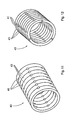
- Different examples of various embodiments of the bearing cage 40 are shown in FIGS. 6 to 14 .
- FIG. 6 an embodiment of the substantially cylindrical bearing cage 40 is shown, in which the bearing cage 40 is provided substantially in one piece and the rolling elements 41 are formed substantially as roller bearing elements 41 .
- the embodiment according to FIG. 6 it may also be provided that in the region of the first and/or second bearing surface 111 , 121 , sliding ribs 42 are formed in the bearing cage 40 , which lead to a particularly smooth-running mounting.
- FIG. 6 an embodiment of the substantially cylindrical bearing cage 40 is shown, in which the bearing cage 40 is provided substantially in one piece and the rolling elements 41 are formed substantially as roller bearing elements 41 .
- sliding ribs 42 are formed in the bearing cage 40 , which lead to a particularly smooth-running mounting.
- FIG. 7 an embodiment of the bearing cage 40 is shown in which the bearing cage 40 is also provided substantially in one piece and the rolling elements 41 are formed substantially as spherical rolling elements.
- the inside of the bearing cage 40 may be formed by means of a wedged profile, the tubular projection of the first section 11 cooperating with the internal profile of the bearing cage 40 fixedly in terms of rotation, such that the outside of the bearing cage 40 may be understood as the first bearing surface 111 .
- the wedged profile of the bearing cage 40 may, as an alternative (but not shown), also be provided on the outside of the bearing cage.
- bearing cage 40 is provided constructed from a plurality of sub-components 43 , rings in particular being provided as sub-components which receive the rolling elements 41 therebetween.
- the rolling elements 41 are formed substantially as spherical rolling elements.
Abstract
Description
- 1 Vehicle seat
- 2 Seat part
- 3 Backrest
- 4 Headrest
- 5 Retaining bar
- 11 First section of the headrest
- 11′ First oblique surface
- 12 Second section of the headrest
- 12′ Second oblique surface
- 13 Third section of the headrest
- 13′ Third oblique surface
- 14′ Fourth oblique surface
- 19 Rotational axis
- 20 Leg spring
- 21, 22 Contact points
- 40 Bearing cage
- 41 Rolling elements
- 42 Sliding ribs
- 43 Partial elements
- 111 First bearing surface
- 121 Second bearing surface
- 122 Comfort section
- 123 Safety section
- Arrow B Rotational direction of the hollow cylinder
- Arrow C Displacement of the padded body
Claims (8)
Applications Claiming Priority (4)
| Application Number | Priority Date | Filing Date | Title |
|---|---|---|---|
| DE102007041520A DE102007041520B3 (en) | 2007-08-31 | 2007-08-31 | Headrest for a vehicle |
| DE102007041520.8 | 2007-08-31 | ||
| DE102007041520 | 2007-08-31 | ||
| PCT/EP2008/007005 WO2009030408A2 (en) | 2007-08-31 | 2008-08-27 | Head rest for a vehicle |
Publications (2)
| Publication Number | Publication Date |
|---|---|
| US20110012399A1 US20110012399A1 (en) | 2011-01-20 |
| US8882193B2 true US8882193B2 (en) | 2014-11-11 |
Family
ID=40157665
Family Applications (1)
| Application Number | Title | Priority Date | Filing Date |
|---|---|---|---|
| US12/675,345 Active 2031-06-12 US8882193B2 (en) | 2007-08-31 | 2008-08-27 | Head rest for a vehicle |
Country Status (7)
| Country | Link |
|---|---|
| US (1) | US8882193B2 (en) |
| EP (1) | EP2195190B1 (en) |
| JP (1) | JP5286363B2 (en) |
| CN (1) | CN101821129B (en) |
| DE (1) | DE102007041520B3 (en) |
| PL (1) | PL2195190T3 (en) |
| WO (1) | WO2009030408A2 (en) |
Cited By (3)
| Publication number | Priority date | Publication date | Assignee | Title |
|---|---|---|---|---|
| US20140203616A1 (en) * | 2013-01-24 | 2014-07-24 | Lear Corporation | Adjustable head restraint assembly |
| US9278635B2 (en) | 2013-01-30 | 2016-03-08 | Lear Corporation | Adjustable head restraint assembly |
| US20170152049A1 (en) * | 2015-11-30 | 2017-06-01 | B/E Aerospace, Inc. | Forward translating headrest |
Families Citing this family (4)
| Publication number | Priority date | Publication date | Assignee | Title |
|---|---|---|---|---|
| US8205941B2 (en) | 2008-07-30 | 2012-06-26 | Trw Vehicle Safety Systems Inc. | Active head restraint for a vehicle seat |
| DE102010023404B4 (en) * | 2010-06-11 | 2015-12-03 | Johnson Controls Gmbh | Headrest for a vehicle seat and method for adjusting a headrest for a vehicle seat |
| DE102010036023B4 (en) * | 2010-08-31 | 2017-10-19 | Adient Luxembourg Holding S.à.r.l. | Headrest adjustable in X direction |
| DE102016110496A1 (en) * | 2016-06-07 | 2017-12-07 | Dr. Ing. H.C. F. Porsche Aktiengesellschaft | Headrest for a motor vehicle seat |
Citations (6)
| Publication number | Priority date | Publication date | Assignee | Title |
|---|---|---|---|---|
| JPS6371816A (en) | 1986-07-16 | 1988-04-01 | ヴアリ・ライト、インコ−パレイテイド | Lens support |
| DE3900495A1 (en) | 1989-01-10 | 1990-07-26 | Bayerische Motoren Werke Ag | Head restraint for a motor-vehicle seat |
| DE19923909A1 (en) | 1998-07-23 | 2000-01-27 | Grammer Automotive Gmbh | Vehicle seat head restraint to prevent whiplash injuries |
| DE19941712C1 (en) | 1999-09-02 | 2000-10-26 | Daimler Chrysler Ag | Vehicle seat headrest has a leading section which is moved forwards and backwards by a scissors mechanism operated by a push member from a unit within the backrest |
| DE102004016474B3 (en) | 2004-03-31 | 2005-08-11 | Johnson Controls Gmbh | Headrest for a vehicle seat comprises a drive unit having components which move toward each other under the action of a force |
| DE102006001143B3 (en) | 2006-01-06 | 2007-04-19 | Johnson Controls Gmbh | Headrest for vehicle, comprises manually operated mechanism for returning unit to prior position after crash |
Family Cites Families (1)
| Publication number | Priority date | Publication date | Assignee | Title |
|---|---|---|---|---|
| JPS59187353U (en) * | 1983-05-31 | 1984-12-12 | 日野自動車株式会社 | car seat pillow |
-
2007
- 2007-08-31 DE DE102007041520A patent/DE102007041520B3/en not_active Expired - Fee Related
-
2008
- 2008-08-27 JP JP2010522240A patent/JP5286363B2/en not_active Expired - Fee Related
- 2008-08-27 WO PCT/EP2008/007005 patent/WO2009030408A2/en active Application Filing
- 2008-08-27 PL PL08785707T patent/PL2195190T3/en unknown
- 2008-08-27 EP EP08785707.4A patent/EP2195190B1/en active Active
- 2008-08-27 CN CN2008801111019A patent/CN101821129B/en active Active
- 2008-08-27 US US12/675,345 patent/US8882193B2/en active Active
Patent Citations (9)
| Publication number | Priority date | Publication date | Assignee | Title |
|---|---|---|---|---|
| JPS6371816A (en) | 1986-07-16 | 1988-04-01 | ヴアリ・ライト、インコ−パレイテイド | Lens support |
| DE3900495A1 (en) | 1989-01-10 | 1990-07-26 | Bayerische Motoren Werke Ag | Head restraint for a motor-vehicle seat |
| DE19923909A1 (en) | 1998-07-23 | 2000-01-27 | Grammer Automotive Gmbh | Vehicle seat head restraint to prevent whiplash injuries |
| DE19941712C1 (en) | 1999-09-02 | 2000-10-26 | Daimler Chrysler Ag | Vehicle seat headrest has a leading section which is moved forwards and backwards by a scissors mechanism operated by a push member from a unit within the backrest |
| DE102004016474B3 (en) | 2004-03-31 | 2005-08-11 | Johnson Controls Gmbh | Headrest for a vehicle seat comprises a drive unit having components which move toward each other under the action of a force |
| WO2005097545A2 (en) | 2004-03-31 | 2005-10-20 | Johnson Controls Gmbh | Headrest, particularly for a motor vehicle |
| JP2007530357A (en) | 2004-03-31 | 2007-11-01 | ジョンソン・コントロールズ・ゲー・エム・ベー・ハー | Especially for automobile headrest |
| US8029055B2 (en) * | 2004-03-31 | 2011-10-04 | Johnson Controls Gmbh | Active head restraint for a vehicle |
| DE102006001143B3 (en) | 2006-01-06 | 2007-04-19 | Johnson Controls Gmbh | Headrest for vehicle, comprises manually operated mechanism for returning unit to prior position after crash |
Non-Patent Citations (2)
| Title |
|---|
| International Search Report corresponding to PCT/EP2008/007005, dated Mar. 20, 2009, 3 pgs. |
| Japanese Office Action (with translation)as received in connection with Japanese application No. 2010-522240; dtd Jan. 22, 2013. |
Cited By (5)
| Publication number | Priority date | Publication date | Assignee | Title |
|---|---|---|---|---|
| US20140203616A1 (en) * | 2013-01-24 | 2014-07-24 | Lear Corporation | Adjustable head restraint assembly |
| US9233631B2 (en) * | 2013-01-24 | 2016-01-12 | Lear Corporation | Adjustable head restraint assembly |
| US9278635B2 (en) | 2013-01-30 | 2016-03-08 | Lear Corporation | Adjustable head restraint assembly |
| US20170152049A1 (en) * | 2015-11-30 | 2017-06-01 | B/E Aerospace, Inc. | Forward translating headrest |
| US9981748B2 (en) * | 2015-11-30 | 2018-05-29 | B/E Aerospace, Inc. | Forward translating headrest |
Also Published As
| Publication number | Publication date |
|---|---|
| CN101821129A (en) | 2010-09-01 |
| EP2195190B1 (en) | 2013-05-15 |
| EP2195190A2 (en) | 2010-06-16 |
| PL2195190T3 (en) | 2013-09-30 |
| DE102007041520B3 (en) | 2009-01-29 |
| WO2009030408A3 (en) | 2009-05-07 |
| US20110012399A1 (en) | 2011-01-20 |
| JP5286363B2 (en) | 2013-09-11 |
| JP2010536653A (en) | 2010-12-02 |
| CN101821129B (en) | 2012-06-20 |
| WO2009030408A2 (en) | 2009-03-12 |
Similar Documents
| Publication | Publication Date | Title |
|---|---|---|
| US8882193B2 (en) | Head rest for a vehicle | |
| US8814265B2 (en) | Head rest for a vehicle | |
| US8029055B2 (en) | Active head restraint for a vehicle | |
| US8408644B2 (en) | Head rest for a vehicle | |
| US7614693B2 (en) | Seating area adjuster | |
| US8915546B2 (en) | Locking device, in particular for a crash-active head restraint of a vehicle | |
| US8491052B2 (en) | Vehicle head restraint | |
| KR101740888B1 (en) | Longitudinal adjuster for a vehicle seat, and vehicle seat | |
| US9919626B2 (en) | Folding and reclining rear seat system | |
| JP5604535B2 (en) | Headrest especially for cars | |
| US9527409B2 (en) | Vehicle seat and utility motor vehicle comprising a vehicle seat | |
| US20130257113A1 (en) | Second Row Vehicle Seat | |
| JP2013526453A (en) | Adjusting device for automobile seat, especially height adjusting device | |
| KR101475212B1 (en) | Head restraint for a vehicle seat | |
| US20170341539A1 (en) | Reclining mechanism of seat | |
| JP4122444B2 (en) | Vehicle seat device | |
| US9150133B2 (en) | Seat cushion inclination adjustment system | |
| KR101678142B1 (en) | Full flat type seat reclining device for recreational vehicle | |
| JP6587378B2 (en) | Multifunctional chair | |
| JP6256678B2 (en) | Vehicle seat device | |
| JP2014155576A (en) | Lumbar support mechanism for vehicle seat |
Legal Events
| Date | Code | Title | Description |
|---|---|---|---|
| AS | Assignment |
Owner name: JOHNSON CONTROLS GMBH, GERMANY Free format text: ASSIGNMENT OF ASSIGNORS INTEREST;ASSIGNORS:FROSE, ERNST-OTTO;DILLINGER, THOMAS;HASLER, ALEXANDER;SIGNING DATES FROM 20100607 TO 20100716;REEL/FRAME:025052/0394 |
|
| STCF | Information on status: patent grant |
Free format text: PATENTED CASE |
|
| MAFP | Maintenance fee payment |
Free format text: PAYMENT OF MAINTENANCE FEE, 4TH YEAR, LARGE ENTITY (ORIGINAL EVENT CODE: M1551) Year of fee payment: 4 |
|
| AS | Assignment |
Owner name: ADIENT LUXEMBOURG HOLDING S.A R.L., LUXEMBOURG Free format text: ASSIGNMENT OF ASSIGNORS INTEREST;ASSIGNOR:JOHNSON CONTROLS GMBH;REEL/FRAME:055026/0876 Effective date: 20200724 |
|
| AS | Assignment |
Owner name: ADIENT GLOBAL HOLDINGS LTD., JERSEY Free format text: ASSIGNMENT OF ASSIGNORS INTEREST;ASSIGNOR:ADIENT LUXEMBOURG HOLDING S.A.R.L.;REEL/FRAME:058751/0678 Effective date: 20220110 |
|
| AS | Assignment |
Owner name: ADIENT US LLC, MICHIGAN Free format text: ASSIGNMENT OF ASSIGNORS INTEREST;ASSIGNOR:ADIENT GLOBAL HOLDINGS LTD.;REEL/FRAME:059086/0636 Effective date: 20220127 |
|
| MAFP | Maintenance fee payment |
Free format text: PAYMENT OF MAINTENANCE FEE, 8TH YEAR, LARGE ENTITY (ORIGINAL EVENT CODE: M1552); ENTITY STATUS OF PATENT OWNER: LARGE ENTITY Year of fee payment: 8 |
|
| AS | Assignment |
Owner name: JPMORGAN CHASE BANK, N.A., AS COLLATERAL AGENT, NEW YORK Free format text: NOTICE OF GRANT OF SECURITY INTEREST IN IP;ASSIGNOR:ADIENT US LLC;REEL/FRAME:061956/0301 Effective date: 20221116 |
|
| AS | Assignment |
Owner name: U.S. BANK TRUST COMPANY, NATIONAL ASSOCIATION, AS COLLATERAL AGENT, WISCONSIN Free format text: NOTICE OF GRANT OF SECURITY INTEREST;ASSIGNORS:CNI ENTERPRISES, INC.;ADIENT US LLC;REEL/FRAME:063085/0391 Effective date: 20230314 |