EP2656027B1 - Vorrichtung und verfahren zur beobachtung und zur messung von raman-streuung - Google Patents
Vorrichtung und verfahren zur beobachtung und zur messung von raman-streuung Download PDFInfo
- Publication number
- EP2656027B1 EP2656027B1 EP11815478.0A EP11815478A EP2656027B1 EP 2656027 B1 EP2656027 B1 EP 2656027B1 EP 11815478 A EP11815478 A EP 11815478A EP 2656027 B1 EP2656027 B1 EP 2656027B1
- Authority
- EP
- European Patent Office
- Prior art keywords
- spectral band
- band
- filter
- viewing
- spectral
- Prior art date
- Legal status (The legal status is an assumption and is not a legal conclusion. Google has not performed a legal analysis and makes no representation as to the accuracy of the status listed.)
- Active
Links
- 238000001069 Raman spectroscopy Methods 0.000 title claims description 154
- 238000000034 method Methods 0.000 title claims description 9
- 230000003595 spectral effect Effects 0.000 claims description 244
- 230000005284 excitation Effects 0.000 claims description 73
- 230000003287 optical effect Effects 0.000 claims description 45
- 238000005259 measurement Methods 0.000 claims description 32
- 238000005286 illumination Methods 0.000 claims description 26
- 230000006641 stabilisation Effects 0.000 claims description 4
- 238000001514 detection method Methods 0.000 claims description 3
- 238000011105 stabilization Methods 0.000 claims description 3
- 238000006073 displacement reaction Methods 0.000 claims description 2
- 238000000926 separation method Methods 0.000 claims 2
- 238000012800 visualization Methods 0.000 description 52
- 239000000523 sample Substances 0.000 description 48
- 238000003841 Raman measurement Methods 0.000 description 11
- 238000009792 diffusion process Methods 0.000 description 9
- 238000010586 diagram Methods 0.000 description 7
- 238000001914 filtration Methods 0.000 description 5
- 239000007789 gas Substances 0.000 description 3
- 239000013307 optical fiber Substances 0.000 description 3
- 238000004458 analytical method Methods 0.000 description 2
- 230000008878 coupling Effects 0.000 description 2
- 238000010168 coupling process Methods 0.000 description 2
- 238000005859 coupling reaction Methods 0.000 description 2
- 239000000835 fiber Substances 0.000 description 2
- 239000007788 liquid Substances 0.000 description 2
- 238000012545 processing Methods 0.000 description 2
- 239000007787 solid Substances 0.000 description 2
- 238000001228 spectrum Methods 0.000 description 2
- 238000001429 visible spectrum Methods 0.000 description 2
- 230000002238 attenuated effect Effects 0.000 description 1
- 230000008901 benefit Effects 0.000 description 1
- 230000008033 biological extinction Effects 0.000 description 1
- 230000005540 biological transmission Effects 0.000 description 1
- 230000001066 destructive effect Effects 0.000 description 1
- 238000003384 imaging method Methods 0.000 description 1
- 230000001939 inductive effect Effects 0.000 description 1
- 238000009434 installation Methods 0.000 description 1
- 238000004519 manufacturing process Methods 0.000 description 1
- 238000012544 monitoring process Methods 0.000 description 1
- 238000000399 optical microscopy Methods 0.000 description 1
- 239000000843 powder Substances 0.000 description 1
- 238000011160 research Methods 0.000 description 1
- 230000004044 response Effects 0.000 description 1
- 230000035945 sensitivity Effects 0.000 description 1
- 238000004611 spectroscopical analysis Methods 0.000 description 1
- 239000000126 substance Substances 0.000 description 1
- 230000007704 transition Effects 0.000 description 1
Images


Classifications
-
- G—PHYSICS
- G01—MEASURING; TESTING
- G01J—MEASUREMENT OF INTENSITY, VELOCITY, SPECTRAL CONTENT, POLARISATION, PHASE OR PULSE CHARACTERISTICS OF INFRARED, VISIBLE OR ULTRAVIOLET LIGHT; COLORIMETRY; RADIATION PYROMETRY
- G01J3/00—Spectrometry; Spectrophotometry; Monochromators; Measuring colours
- G01J3/28—Investigating the spectrum
- G01J3/44—Raman spectrometry; Scattering spectrometry ; Fluorescence spectrometry
-
- G—PHYSICS
- G01—MEASURING; TESTING
- G01J—MEASUREMENT OF INTENSITY, VELOCITY, SPECTRAL CONTENT, POLARISATION, PHASE OR PULSE CHARACTERISTICS OF INFRARED, VISIBLE OR ULTRAVIOLET LIGHT; COLORIMETRY; RADIATION PYROMETRY
- G01J3/00—Spectrometry; Spectrophotometry; Monochromators; Measuring colours
- G01J3/02—Details
- G01J3/0205—Optical elements not provided otherwise, e.g. optical manifolds, diffusers, windows
- G01J3/021—Optical elements not provided otherwise, e.g. optical manifolds, diffusers, windows using plane or convex mirrors, parallel phase plates, or particular reflectors
-
- G—PHYSICS
- G01—MEASURING; TESTING
- G01J—MEASUREMENT OF INTENSITY, VELOCITY, SPECTRAL CONTENT, POLARISATION, PHASE OR PULSE CHARACTERISTICS OF INFRARED, VISIBLE OR ULTRAVIOLET LIGHT; COLORIMETRY; RADIATION PYROMETRY
- G01J3/00—Spectrometry; Spectrophotometry; Monochromators; Measuring colours
- G01J3/02—Details
- G01J3/0205—Optical elements not provided otherwise, e.g. optical manifolds, diffusers, windows
- G01J3/0248—Optical elements not provided otherwise, e.g. optical manifolds, diffusers, windows using a sighting port, e.g. camera or human eye
-
- G—PHYSICS
- G01—MEASURING; TESTING
- G01J—MEASUREMENT OF INTENSITY, VELOCITY, SPECTRAL CONTENT, POLARISATION, PHASE OR PULSE CHARACTERISTICS OF INFRARED, VISIBLE OR ULTRAVIOLET LIGHT; COLORIMETRY; RADIATION PYROMETRY
- G01J3/00—Spectrometry; Spectrophotometry; Monochromators; Measuring colours
- G01J3/02—Details
- G01J3/10—Arrangements of light sources specially adapted for spectrometry or colorimetry
-
- G—PHYSICS
- G01—MEASURING; TESTING
- G01N—INVESTIGATING OR ANALYSING MATERIALS BY DETERMINING THEIR CHEMICAL OR PHYSICAL PROPERTIES
- G01N21/00—Investigating or analysing materials by the use of optical means, i.e. using sub-millimetre waves, infrared, visible or ultraviolet light
- G01N21/62—Systems in which the material investigated is excited whereby it emits light or causes a change in wavelength of the incident light
- G01N21/63—Systems in which the material investigated is excited whereby it emits light or causes a change in wavelength of the incident light optically excited
- G01N21/65—Raman scattering
Definitions
- the present invention relates to the field of Raman spectrometry. More specifically, the invention relates to a device and a display method for a Raman spectrometer.
- Raman spectroscopy Since the arrival of laser sources, Raman spectroscopy has grown tremendously and today finds applications in a wide variety of fields, ranging from fundamental research to industrial process control applications.
- Raman spectroscopy is based on the measurement of transitions between vibrational states of a polyatomic, molecular or ionic structure (and on the rotational states in the case of gas), regardless of the physical state of the sample (gas , liquid, amorphous or crystalline solid).
- a sample illuminated by a monochromatic light source a laser
- the spectrum obtained is composed of three scattering sources: the Rayleigh bands (elastic scattering), Stokes and Anti-Stokes (inelastic scattering).
- Raman frequencies are specific for each sample and are independent of the laser frequency. Raman spectroscopy thus allows a non-destructive chemical analysis of solids, liquids, powders or gases.
- Raman spectrometry More recently, the miniaturization of optical components has made it possible to couple Raman spectrometry to standard optical microscopy to allow the analysis of samples with micrometric spatial resolution.
- the excitation laser beam is generally focused by an objective or an optical lens.
- Different Raman spectrometry devices have a visualization system that allows the sample to be illuminated and an image of the sample to be formed on a screen.
- a viewing system is generally based on the use of a white light source (conventional lamp), a viewing camera and a retractable optical component, such as a semi-transparent slide, on the optical path. of the measuring instrument.
- the installation of the display device makes it possible to focus on the sample before the measurement, for example by means of an autofocus system.
- the lighting and display device In such a device, to perform a measurement of the sample by Raman spectrometry, the lighting and display device must be removed from the optical path, for example by retracting the semi-transparent plate out of the optical path.
- a retractable optical component supposes a mechanical movement which involves a risk of movement.
- the lack of reproducibility of the opto-mechanical movement can produce a different focus of the sample seen by the visualization system and by the Raman measurement system.
- the excitation laser is liable to generate stray light towards the viewing camera, which may saturate the camera sensor and prevent correct viewing of the sample.
- the permanent presence of an additional optical component, such as a semi-transparent plate, on the optical path necessarily results in a drop in the Raman signal detected.
- the illumination source is capable of generating stray light by scattering not only on the sample but also on the internal components of the device and thus disturb the measurement of the Raman signals.
- the difficulty in measuring Raman signals comes essentially from the very low intensity of Raman scattering compared to the intensity of Rayleigh scattering. It is therefore not possible, with current systems, to simultaneously perform a Raman measurement and the visualization of a sample.
- Patent documents WO2008052221 , WO2004081549 and WO2010 / 024397 propose to combine a Raman spectrometry measurement system having an excitation source in the near infrared domain with an imaging system based on white light illumination.
- One of the aims of the invention is to provide a device and a method for Raman visualization and spectrometry.
- An aim of the invention is to provide a device and a method allowing simultaneously the visualization and the measurement by Raman spectrometry of a sample.
- the object of the present invention is to remedy these drawbacks and relates more particularly to an optical device for Raman spectrometry and for viewing a sample according to claim 1.
- the invention also relates to a Raman spectrometry method according to claim 11.
- the invention proposes an arrangement of filters making it possible to carry out Raman and visualization of the sample without moving parts and simultaneously.
- the idea is to use a specific spectral range for the illumination and visualization of the sample, this spectral range being separate from that of the laser and the induced Raman range.
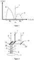
- the figure 1 very schematically represents the spectral distribution of the intensity of different measurement and display beams.
- the excitation laser beam has a wavelength ⁇ 0 and a spectral band B 0 centered on the wavelength ⁇ 0 , the spectral band B 0 being very narrow.
- the excitation beam (1) generates by Raman scattering on a sample a Raman scattering beam whose lines are located in a spectral band B R represented schematically by the curve (3) on the figure 1 .
- One aspect of the invention consists in using a display beam having a spectral band B V distinct from the spectral band B 0 of the laser and from the spectral band B R which it is sought to measure.
- the figure 2 schematically represents an exemplary embodiment of a device according to an embodiment of the invention so as to illustrate the path of the different beams.
- the device of the figure 2 makes it possible to superimpose an incident laser beam and an incident lighting beam and simultaneously to separate the beam diffused by the sample (7) and collected by the objective (6) according to its different spectral components, more precisely according to the spectral bands B 0 , B V and B R.
- the beam (21) is a backscattering beam from the excitation laser having a spectral band B 0 (Rayleigh scattering).
- the beam (3) is the Raman scattering beam which has a spectral component B R.
- the viewing beam (22) is a Rayleigh backscattering beam of the illumination beam (2) which has a spectral component B v .
- the filter (12) transmits the Raman scattering beam (3) and reflects the Rayleigh scattering beams (21) and (22).
- the filter (13) transmits the viewing beam (22) scattered by the sample (7) and reflects the Rayleigh scattering beam at the wavelength of the laser.
- a splitter plate (16) transmits the viewing beam (22) diffused by the sample, for example in the direction of a viewing camera (not shown).
- the Raman beam (3) can be transmitted in the direction of a Raman spectrometer in order to provide the measurement of the Raman lines in the spectral band B R.
- the device of the figure 2 thus makes it possible to visualize the sample thanks to the visualization beam (22) and simultaneously to perform a Raman measurement thanks to the Raman scattering beam (3) which is separated from the Rayleigh diffusions of the laser beam and of the illumination beam.
- the figure 3 shows a device according to a preferred embodiment of the invention.
- the device of the figure 3 can be coupled directly to a Raman spectrometer or deported relative to the Raman spectrometer to be placed as close as possible to the sample, the device then being connected to a Raman spectrometer by optical fibers.
- the housing (20) includes an input (10) for coupling an exciting laser beam and directing it to a first deflection mirror (14).
- the laser beam (1) is transmitted by the filter (13) and then reflected by the filter (12) to be transmitted towards the sample through the optical focusing component (15).
- the housing (20) comprises a display source (11) which is for example a green LED emitting in a wavelength range between 500 and 550 nm.
- the source of visualization (11) generates a visualization beam (2) which is directed towards a splitter plate (16), then transmitted in the direction of the filter (13).
- the filter (13) reflects the beam (2) towards the filter (12) which also reflects the viewing beam (2) towards the sample, so as to superimpose it on the laser excitation beam (1).
- the scattering beam collected through the window (15) comprises a Raman scattering beam (3) which is transmitted through the filter (12) towards a module (18) which can be either a Raman spectrometer or a connector of fibers so as to transmit the Raman beam (3) to a remote Raman spectrometer.
- the beam scattered by the sample at the wavelength ⁇ 0 of the laser is reflected by the filter (12), transmitted by the filter (13) and redirected to the input / output (10).
- the collected beam also comprises a component in the spectral band B V of the display source.
- the backscattered viewing beam (22) is reflected by the filter (12) and by the filter (13) then transmitted by the splitter plate (16). This viewing beam (22) is directed towards a viewing camera (17).
- a prototype of a remote fiber probe, based on the diagram of the figure 3 was carried out for an excitation laser having a wavelength ⁇ 0 of 660nm, but this principle can be applied to any device.
- the filter (12) reflects the laser (660nm), the low wavelength illumination (less than 660nm) and the light reflected by the sample.
- the filter (12) transmits the Raman scattering beam for wavelengths from 665 nm, the Raman range extending in wavenumber between 400 and 3500 cm -1 .
- the filter (13) transmits the excitation laser at 660nm and reflects the illumination beam at low wavelength.
- the splitter blade (16) makes it possible to separate the illumination beam (2) which goes from the illumination source to the sample from the viewing beam (22) which goes from the sample to a viewing camera.
- the device of the figure 3 is compatible with a confocal video system.
- the excitation laser is coupled to the input connector (10) via an optical fiber with a core diameter of 5-6 microns.
- the probe is connected to a Raman spectrometer via optical fiber having a core diameter of about 100 microns.
- the light source is a green LED with a 15 ° opening and a light intensity of approximately 6800 mcd.
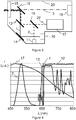
- the figure 4 schematically represents the relative spectral response of the different sources and filters used.
- the laser beam (1) has a wavelength ⁇ 0 and a very narrow spectral band B 0.
- the curve (2) corresponding to the spectral emission curve of the display source (11) is observed.
- the spectral detection curve of the viewing camera (17) has a very broad spectrum with maximum sensitivity around the spectral band B V of the viewing source.
- the filter (12) is a high pass filter having a cut-off wavelength located just above the wavelength ⁇ 0 of the laser while the filter (13) passes the wavelength of the laser and reflects the wavelengths in the viewing spectral band B V.
- the figure 5 schematically represents a first case, not forming part of the invention, according to which the excitation wavelength ⁇ 0 defines a spectral band B 0 .
- the excitation wavelength ⁇ 0 defines a spectral band B 0 .
- the spectral viewing band B V is located at wavelengths less than the excitation wavelength ⁇ 0 .
- the laser can have a wavelength of 660 nm and visualization can be done in the blue-green-yellow region of the visible spectrum.
- the excitation laser beam (1) is shown in solid line and the Raman scattering beam (3) Stokes in dash-dot line.
- a common dashed line (2) shows the illumination beam incident on the sample and the display beam diffused by the sample, which are superimposed on the outward and return path up to a separator blade (16) not shown.
- the figure 6 shows a first embodiment, not forming part of the invention, using the distribution of the spectral bands of the figure 5 .
- the laser excitation beam (1) is transmitted by a filter (13a) and then reflected by a filter (12a) towards a focusing objective (6).
- the viewing beam (2) is reflected by the filter (13a) then by the filter (12a) towards the objective (6).
- the collected beam comprises the Raman scattering beam (3) which is transmitted by the filter (12a).
- the collected scattered beam also comprises a viewing beam which is reflected by the filter (12a) then by the filter (13a).
- the filter (13a) is a high-pass or band-pass filter having a cut-off wavelength situated between the viewing band B V and the band B 0 of the laser.
- the filter (12a) is a high pass filter having a cut-off wavelength located between the wavelength ⁇ 0 of the laser and the Raman scattering band B R.
- the filter (13a) therefore serves to superimpose the excitation laser beam and the illumination beam in the direction of the sample and on the scattering beam to separate the viewing beam from the backscatter at the wavelength of the laser.
- the filter (12a) serves to separate on the one hand the beam from the Raman scattering (3) and on the other hand the spectral components of the scattering beam in the spectral band B 0 of the laser and in the spectral band B V of the beam visualization.
- the figure 7 shows a second embodiment of a device, not forming part of the invention, still using the spectral distribution according to the diagram of the figure 5 .
- the laser beam (1) is first reflected by a filter (13b) before being reflected on a filter (12b).
- the lighting beam (2) is transmitted by the filter (13b) before being reflected by the filter (12b).
- the scattered and collected beam is directed towards the first filter (12b) which transmits the Raman scattering beam (3) and reflects the components of the scattered beam in the spectral band B 0 of the laser and in the spectral band B V of the viewing beam 2.
- the filter (13b) separates the scattered viewing beam from the scattered beam at the wavelength of the laser.
- the filter (12b) is a high pass filter having a cutoff wavelength located between the wavelength ⁇ 0 of the laser and the Raman spectral band B R.
- the filter (13b) is a low-pass or band-cut filter having a cut-off wavelength located between the viewing spectral band B V and the spectral band B 0 which transmits the beam in the spectral band B V and reflects a beam having wavelengths in the spectral band B 0 .
- the figure 8 schematically shows a third embodiment, not forming part of the invention, based on the spectral distribution of the diagram of the figure 5 .
- the excitation laser beam (1) is transmitted by a filter (13c) then by a filter (12c) towards the objective (6).
- the lighting beam (2) is reflected on the filter (13c) and transmitted by the filter (12c).
- the Raman scattering beam (3) is reflected by the filter (12c).
- the scattering beam (2) in the spectral viewing band B V is transmitted by the filter (12c) and reflected by the filter (13c).
- the filter (13c) is a high-pass or band-pass filter having a cut-off wavelength situated between the spectral band B V and the band B 0 which transmits the band B 0 and reflects the band B V.
- the filter (12c) is a low-pass filter having a cut-off wavelength between the band B 0 , and the Raman band B R which transmits the wavelength of the spectral band B V and of the spectral band B 0 and reflects a beam having wavelengths in the spectral band B R.
- the figure 9 shows a fourth embodiment, not forming part of the invention, according to the spectral distribution of the diagram of the figure 5 .
- the device includes a filter (12d), a filter (13d) and an objective (6).
- the excitation laser beam (1) is reflected on the filter (13d) then transmitted by the filter (12d) towards the objective (6).
- the lighting and visualization beam (2) is transmitted by the filter (13d) and the filter (12d).
- the Raman scattering beam (3) collected is reflected by the filter (12d) while the scattering beam in the spectral band B V of the viewing beam is transmitted by the filter (12d) and by said filter (13d).
- the filter (13d) is a low-pass or band-cut filter having a cut-off wavelength situated between the viewing band B V and the band B 0 of the laser which transmits the viewing band B V and reflects the band B 0 .
- the filter (12d) is a low pass filter which transmits the bands B 0 and B V and reflects the Raman diffusion band B R.
- the filter (12d) has a cut-off wavelength between the band B 0 and the band B R.
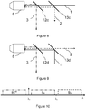
- the figure 10 represents a case of distribution of the spectral bands according to the invention: the laser excitation spectral band, the Raman Stokes measurement bands (band spectral B R ) and anti-Stokes Raman (spectral band B R aS ) and the visualization band Bv.
- the wavelength ⁇ 0 of the excitation laser is located at 473nm while the viewing spectral band B V is located in the yellow-red part of the visible spectrum, for example in a range of wavelengths above 600 nm.
- the Raman Stokes band is located at wavelengths greater than the laser excitation wavelength ⁇ 0 and less than a wavelength ⁇ 1 which is itself less than the viewing band B V.
- the Anti-Stokes Raman scattering band is located at wavelengths less than the laser excitation wavelength ⁇ 0.
- the figure 11 shows a first embodiment according to the spectral distribution of the figure 10 .
- the excitation laser beam (1) is transmitted by a filter (13e) and reflected by a filter (12e).
- the lighting and display beam (2) is transmitted by the filter (12e) which retransmits the beam diffused in the display band B V.
- the filter (12e) reflects the Raman scattering beam (3).
- the filter (13e) reflects the Raman scattering beam (3).
- the filter (13e) is a low-pass filter which transmits the band B 0 and reflects the band B R which therefore has a cut-off wavelength situated between the band B 0 and the band B R.
- the filter (12e) is a high pass filter which transmits the viewing band B V and reflects the spectral bands B 0 and B R.
- the filter (12e) is a filter having a cut-off wavelength between the Raman band B R and the visualization band B V.
- the filter (13e) is a bandpass filter which transmits the B 0 band and reflects the Raman B R Stokes bands and the Raman Anti-Stokes band B R aS
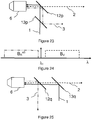
- the figure 12 schematically represents a second embodiment based on the spectral distribution of the diagram of the figure 10 .
- the device of the figure 12 comprises a filter (13f) which reflects the excitation beam to the laser (1).
- the illumination and visualization beam (2) is transmitted by the filter (12f) which reflects the scattered Raman beam (3) and transmits the part of the scattered beam in the visualization band B V.
- the filter (13f) separates the Raman beam (3) from the Rayleigh scattered beam at the wavelength of the laser.
- the filter (12f) is a high pass filter which transmits the viewing band B V and reflects the spectral bands B 0 and B R and has a cut-off wavelength between B R and B V.
- the filter (13f) transmits the Raman scattering spectral band B R and reflects the band B 0 of the laser.
- the filter (13f) is a high-pass filter having a cut-off wavelength situated between the spectral bands B 0 and B R.
- the filter (13f) is a notch filter which reflects the spectral band B 0 of the excitation beam and transmits the Raman scattering bands B R Stokes and Anti-Stokes B R aS .
- the figure 13 shows a third embodiment according to the spectral distribution of the figure 10 .
- the filter (12g) superimposes the excitation laser beam (1) and the illumination and visualization beam (2) by reflecting the laser beam (1) and transmitting the illumination and visualization beam (2) in the spectral band B V.
- the filter (12g) transmits the viewing beam in the spectral band B V and the Raman scattering beam (3) and reflects the Rayleigh scattering beam in the spectral band B 0 .
- the filter (13g) transmits the viewing beam (2) in the spectral band B V and reflects the Raman scattering beam (3).
- the filter (13g) is a high pass filter having a cutoff wavelength located between the Raman spectral band B R and the visualization band B V so as to transmit the visualization band B V and to reflect the spectral band B R.
- the filter (12g) is a high-pass filter which transmits the spectral band B R , the spectral band B V and reflects the spectral band B 0 .
- the filter (12g) is a notch filter which reflects the spectral band B 0 , transmits the Raman anti-Stokes spectral band, the Raman spectral band Stokes and the viewing spectral band B V.
- the figure 14 shows a fourth embodiment according to the spectral distribution of the figure 10 .
- the filter (12h) makes it possible to superimpose the excitation laser beam (1) and the illumination and display beam (2) in the direction of the sample.
- the filter (12h) reflects the signal scattered by Rayleigh scattering in the spectral band B 0 , transmits the viewing beam in the spectral band B V and the Rayleigh scattering beam in the spectral band B R or B R as .
- the filter (13h) is a low pass filter which transmits the Raman diffusion band B R and reflects the spectral viewing band B V.
- the filter (12h) is a high-pass filter having a cut-off wavelength between the spectral band B 0 and the spectral band B R so as to reflect the band spectral B 0 and to transmit the spectral bands B R and B V.
- the filter (12h) is a notch filter which reflects the spectral band B 0 and transmits the spectral bands B R Stokes B R aS anti- Stokes as well as the lines of the spectral band of visualization B V.
- the figure 15 represents a fifth embodiment for a measurement of the Raman Stokes lines according to the distribution of the figure 10 .
- the filter (13i) makes it possible to superimpose the excitation laser beam (1) and the illumination and display beam (2) in the direction of the object 6 and the sample.
- the filter (12i) transmits both the laser excitation beam (1) and the visualization beam (2).
- the filter (12i) separates the Raman scattering beam (3) from the viewing beam (2).
- the filter (13i) reflects the viewing beam (2) and transmits the Rayleigh scattered beam at the wavelength of the laser.
- the filter (13i) is a low pass filter which transmits the band B 0 and reflects the band Bv.
- the filter (12i) is a wide notch filter which transmits the band B 0 , reflects the Raman band B R and transmits the visualization band B V.
- the figure 16 represents another embodiment for the measurement of Raman Stokes lines alone, according to the spectral distribution of the fig. 10 .
- the device of the figure 16 comprises a filter (13j) which makes it possible to superimpose the excitation laser beam (1) and the visualization beam by reflecting the laser beam in the spectral band B 0 and by transmitting the visualization beam in the spectral band B V.
- the filter 12j simultaneously transmits the excitation and lighting and visualization beam (2).
- the filter (12j) reflects the Raman scattering beam (3) in the spectral band B R and transmits the Rayleigh scattering beam at the wavelength of the laser in the spectral band B 0 as well as the visualization beam (2) scattered by the sample in the spectral band B V.
- the filter (13j) separates the viewing beam (2) in the spectral band B V from the Rayleigh scattering beam in the spectral band B 0 .
- the filter (12j) is a wide notch filter which transmits the spectral band B 0 reflects the Raman spectral band B R and transmits the visualization band B V.
- the filter (13j) is a high-pass filter having a cut-off wavelength between the spectral band B 0 and the display band B V.
- the figure 17 represents another embodiment related to the spectral distribution of the diagram of the figure 10 .
- the device comprises a filter (12k) which makes it possible to superimpose the excitation laser beam (1) and the visualization beam (2) by transmitting the beam in the spectral band B 0 and by reflecting the beam in the spectral band B V .
- the collected scattering beam comprises a spectral component in the viewing band B V which is reflected by the filter (12k).
- the filter (12k) is a low pass filter which transmits the spectral band B 0 and the Raman scattering spectral band B R and which reflects the spectral band B V.
- the filter (13k) transmits the Raman scattering beam (3) in the Raman spectral band and reflects the Rayleigh scattering beam in the spectral band B 0 .
- the filter (13k) can be a high-pass filter having a cut-off wavelength situated between the spectral band B 0 and the Raman Stokes spectral band B R.
- the filter (13k) is a notch filter which reflects the spectral band B 0 and transmits the Raman Stokes B R and Anti-Stokes B R aS scattering spectral bands.
- the figure 18 shows another embodiment for a spectral distribution following the path of the figure 10 .
- the device comprises a filter (12l) which makes it possible to superimpose the laser excitation beam and the visualization beam (2) by transmitting the laser excitation beam (1) and by reflecting the visualization beam (2).
- the filter (12l) makes it possible to extract the viewing beam in the spectral viewing band B V and transmits the Raman scattering signal in the band B R as well as the Rayleigh scattering signal in the spectral band B 0 .
- the filter (12l) is a low pass filter which transmits the band B 0 and the band B R and reflects the band B V and therefore has a cut-off wavelength located above the wavelength ⁇ 0 between the Raman band B R and the spectral band B V for visualization.
- the filter (13l) reflects the Raman scattering signal and transmits the Rayleigh scattering signal in the spectral band B 0 .
- the filter (13l) is a low-pass filter which transmits the spectral band B 0 and reflects the Raman spectral band B R.
- the filter (13l) is a bandpass filter which transmits only the spectral band B 0 and which reflects the Raman Stokes B R scattering spectral bands. and Anti-Stokes B R aS
- the figure 19 represents another case of spectral distribution of the laser excitation display bands in the case where the anti-Stokes and Stokes Raman lines are measured; this case not forming part of the invention.
- the viewing band B V is here located at wavelengths less than the scattering band of Anti-Stokes B R aS Raman lines.
- the filter (12m) makes it possible to superimpose the excitation laser beam (1) and the visualization beam (2).
- the excitation beam (1) being transmitted and the viewing beam (2) being reflected by the filter (12m).
- the filter (12m) makes it possible to extract a scattered beam in the viewing band B v and to transmit the Raman scattering beam (3) as well as the Rayleigh scattering beam in the spectral band B 0 .
- the filter (12m) is a high pass filter having a cutoff wavelength between the viewing band B V and the anti-Stokes Raman scattering band.
- the filter (12m) transmits the signals in the bands B 0 , B R aS and possibly B R Stokes and reflects the viewing band B V.
- the filter (13m) is a high-pass filter which transmits the spectral band B 0 and reflects the spectral band of anti-Stokes Raman scattering.
- the filter (13m) is a bandpass filter which transmits the spectral band B 0 and reflects the Raman Stokes and anti-Stokes scattering bands.
- the figure 21 shows another embodiment, not forming part of the invention, corresponding to the distribution shown schematically on the figure 19 .
- the device includes a filter (12n) and a filter (13n).
- the filter (12n) makes it possible to superimpose the excitation laser beam (1) and the visualization beam (2) by reflecting the beam (2) and transmitting the beam (1).
- the filter (12n) makes it possible to extract the scattered beam in the viewing band B V and to transmit the scattered beams in the B 0 band as well as in the Raman scattering band.
- the filter (13n) makes it possible to separate the beam scattered in the spectral band B 0 of the excitation laser of the Raman scattering beam (3).
- the filter (12n) is a high-pass filter which transmits the spectral bands B 0 and B R aS (Raman anti-Stokes) and which reflects the spectral viewing band B V
- the filter (13n) is a low-pass filter which transmits the anti-Stokes diffusion band B R aS and reflects the spectral band B 0
- the filter (13n) is a notch filter which reflects the spectral band B 0 and transmits the Raman Stokes B R scattering bands and Anti-Stokes B R aS .
- the figure 22 shows yet another embodiment, not forming part of the invention, according to the diagram of figure 19 in which a filter (12o) makes it possible to superimpose the excitation laser beam (1) and the illumination and visualization beam (2) by reflecting the laser beam (1) and transmitting the illumination and visualization beam (2) in the spectral band B V.
- the filter (12o) transmits the scattered beam in the viewing band B V and reflects the scattered beam in the Raman scattering bands and in the Rayleigh scattering band B 0 .
- the filter (12o) is a low-pass filter which transmits the viewing band B V and reflects the B R Anti-Stokes diffusion bands, the B 0 band and possibly the Raman stokes diffusion band.
- the filter (13o) transmits the beam scattered in the Raman spectral bands and reflects the Rayleigh beam scattered in the spectral band B 0 of the laser.
- the filter (13o) is a low-pass filter which transmits the anti-Stokes Raman diffusion band and reflects the spectral band B 0 .
- the filter (13o) is a notch filter which reflects the spectral band B 0 and transmits the Raman stokes B R and Anti-Stokes scattering bands B R aS .
- the figure 23 describes a fourth embodiment, not forming part of the invention, in connection with the spectral distribution of the figure 19 .
- the filter (12p) makes it possible to superimpose the excitation laser beam (1) and the illumination and display beam (2) by reflecting the laser beam and transmitting the illumination and visualization beam in the spectral band B V.
- the filter (12p) transmits the beam display (2) in the spectral band B V and reflects the Raman scattering signals in the spectral band B R and the beam scattered by Rayleigh scattering in the spectral band B 0
- the filter (12p) thus makes it possible to extract the beam from visualization (2).
- the filter (13p) makes it possible to separate the Rayleigh scattering beam in the spectral band B 0 and the Raman scattering beam (3).
- the filter (12p) is a low pass filter which transmits the viewing band B V reflects the Raman Anti-Stokes scattering band and the spectral band B 0 . If one wishes to measure only the Anti-Stokes lines, the filter (13p) is a high-pass filter which transmits the spectral band B 0 and reflects the Raman Anti-Stokes B R aS scattering band. where one wishes to simultaneously measure the Stokes and anti-Stokes lines, the filter (13p) is a bandpass filter which transmits the spectral band B 0 and reflects the Raman stokes B R and anti-Stokes B R aS scattering band
- the figure 24 represents a fourth case, not forming part of the invention, where it is desired to measure only the scattering of the anti-Stokes Raman lines and where the spectral viewing band B V is located above the B 0 band of the laser of excitement.
- the figures 25 to 28 show different embodiments, not forming part of the invention, depending on the spectral distribution of the figure 24 .
- a filter (13q) makes it possible to superimpose the excitation beam which is reflected by the filter (13q) and a display beam (2) transmitted by this filter.
- a filter (12q) reflects the scattered beam in the anti-Stokes Raman band and transmits the scattered beam in the viewing band and in the spectral band B 0 .
- the filter (13q) makes it possible to transmit the signal diffused in the viewing band B V and to reflect the Rayleigh scattering beam in the spectral band B 0 .
- the filter (12q) is a high-pass filter having a cut-off wavelength between the Raman Anti-Stokes spectral band B R aS and the spectral band B 0 which therefore transmits the spectral bands B 0 and B V of visualization and reflects the Raman Anti-Stokes spectral band.
- the filter (13q) is a high-pass or band-cut filter having a cut-off wavelength situated between the viewing band and the band B 0 which transmits the spectral band B V and reflects the spectral band B 0 .
- the figure 26 describes a second embodiment, not forming part of the invention, in connection with the spectral distribution of the figure 24 .
- the filter (13r) makes it possible to superimpose the excitation laser beam (1) transmitted and the illumination and display beam (2) which is reflected by the filter (13r).
- the filter (12r) transmits the combined excitation and visualization beam.
- the filter (12r) reflects the Raman Anti-Stokes scattering beam (3) and transmits the scattered beams in the spectral band B 0 and in the viewing band B v .
- the filter (13r) separates the beam scattered in the viewing band B v and the beam scattered in band B 0 .
- the filter (12r) is a high pass filter having a cutoff wavelength between the Raman Anti-Stokes scattering and the B 0 band.
- the filter (12r) therefore reflects the Raman Anti-Stokes band and transmits the spectral bands B 0 and B V.
- the filter (13r) is a low-pass or band-pass filter which transmits the spectral band B 0 and reflects the visualization band B V.
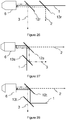
- the figure 27 describes a third embodiment, not forming part of the invention, in connection with the spectral distribution of the figure 24 .
- the filter (12s) makes it possible to superimpose the reflected laser excitation beam (1) and the transmitted illumination and display beam (2). On the collected scattered beam, the filter (12s) transmits the scattered beam in the viewing band B V and reflects the scattered beam in the spectral band B 0 and in the anti-Stokes B R aS Raman scattering band.
- the filter (12s) is a high-pass filter, the cut-off wavelength of which is situated between the spectral band B 0 and the display band B V.
- the filter (13s) reflects the Raman scattering beam (3) in the Anti-Stokes scattering band B R aS and transmits the Rayleigh scattering beam in the spectral band B 0 .
- the filter (13s) is a high-pass or band-pass filter whose cut-off wavelength is located between the Raman Anti-Stokes diffusion band and the B 0 band so as to transmit the B 0 band and reflects the Raman Anti-Stokes broadcast band.
- the filter (12t) makes it possible to superimpose the excitation laser beam (1) and the visualization beam (2).
- the filter (12t) reflects the scattered beam in the anti-Stokes Raman scattering band and in the spectral band B 0 and transmits the scattered beam in the viewing band B V.
- the filter (13t) transmits the scattered beam in the anti-Stokes Raman scattering band and reflects the scattered beam in the spectral band B 0 .
- the filter (12t) is a high-pass filter having a cut-off wavelength situated between the spectral band B 0 and the visualization band B V.
- the filter (12t) therefore transmits the display band B v and reflects the spectral band B 0 as well as the anti-Stokes Raman scattering band.
- the filter (13t) is a low-pass or band-cut filter which transmits the anti-Stokes Raman scattering band reflects the band scattered in the spectral band B 0 .
- the different variant embodiments described in connection with the figures 2 , 6-8 , 11-18 , 20-23 and 25-28 all relate to a backscatter configuration.
- the same principle also applies to other Raman scattering configurations (forward scattering, or lateral scattering), in which case the means for superimposing the laser excitation beam and the illumination beam are separate from the means for filtering the scattering beam.
- the principle the use of disjoint spectral ranges nevertheless applies in the same way.
- Those skilled in the art will therefore adapt the device and the method of the invention to the different experimental configurations of Raman spectrometry.
- the same principle is used with several excitation laser wavelengths at the same time and multi-cut filters to separate the different excitation spectral bands, the viewing spectral band and the bands.
- Raman spectral values associated respectively with each of the excitation laser wavelengths.
- a notch filter simultaneously performs a high-pass filter function and a low-pass filter function. Therefore, it is equivalent to replacing a high pass and low pass filter with a notch filter.
- the filters can be produced by dielectric stacks or by the VBG (Volume Bragg Grating) technique.
- VBG Volume Bragg Grating
- the invention discloses an arrangement of filters without moving parts which makes it possible to carry out a Raman measurement and to visualize the sample, the visualization and the measurement being able to be simultaneous.
- the display device of the invention is compact and has a size reduced by half compared to a display system of the prior art based on an optical component which can be retracted onto the optical path.
- the device and the method are easy to use, since they do not require a motor or moving parts.
- the absence of a moving part also makes the device robust.
- the device hardly induces any losses on the Raman signal (extremely minimal losses of a few percent).
- the extinction ratio of the filters can be chosen so that a very small part of the beam coming from the Rayleigh scattering of the excitation laser beam is transmitted towards the sample display system.
- the display system advantageously makes it possible to simultaneously visualize the sample and the position of the excitation laser beam on the sample.
- the Rayleigh scattering beam being very attenuated, it does not present any risk of saturation of the display sensor, for example of a CCD camera.
- the device of the invention simultaneously allows the visualization of a sample and a Raman measurement of this sample without inducing high optical intensity losses.
- this device is composed of fixed elements.
- the devices of the prior art involve either a sequential visualization and a measurement, or a concomitant visualization of a measurement, but with high losses in optical intensity.
- a device of the prior art based on one or two beam splitters (of the splitter blade or splitter cube type) has a limited efficiency between 6 and 25%.
- the efficiency (in optical transmission) of a device of the invention composed of two filters is greater than or equal to 90%, or even to 95%.
- the device of the invention has the advantage of considerably reducing optical losses, and of allowing the measurement of a Raman signal which is always very weak.
Landscapes
- Physics & Mathematics (AREA)
- Spectroscopy & Molecular Physics (AREA)
- General Physics & Mathematics (AREA)
- Health & Medical Sciences (AREA)
- Nuclear Medicine, Radiotherapy & Molecular Imaging (AREA)
- Life Sciences & Earth Sciences (AREA)
- Chemical & Material Sciences (AREA)
- Analytical Chemistry (AREA)
- Biochemistry (AREA)
- General Health & Medical Sciences (AREA)
- Immunology (AREA)
- Pathology (AREA)
- Investigating, Analyzing Materials By Fluorescence Or Luminescence (AREA)
Claims (11)
- Optische Vorrichtung für Raman-Spektrometrie und für die Darstellung einer Probe (7), wobei die Vorrichtung- eine Anregungslaserquelle (10), die geeignet ist, einen Anregungslaserstrahl (1) zu erzeugen, der ein um eine Wellenlänge λ0 zentriertes Spektralband B0 aufweist,- Erfassungsmittel (18), die geeignet sind, einen Strahl (3) mit Raman-Streuung in einem Spektralband zu erfassen, das aus einem Meßband BR aS der Anti-Stokes-Linien und einem Meßband BR der Stokes-Linien besteht, aufweist,dadurch gekennzeichnet, daß die Vorrichtung- eine Darstellungslichtquelle (11), die geeignet ist, einen Darstellungsstrahl (2) mit einem vom Spektralband B0 des Lasers und vom zu messenden Spektralband des Strahls (3) mit Raman-Streuung verschiedenen Spektralband BV zu erzeugen, wobei die Wellenlänge λ0 der Anregungslaserquelle (10) bei 473 nm liegt, das Spektralband Bv des Darstellungsstrahls in einem Wellenlängenbereich oberhalb 600 nm liegt, wobei das Spektralband B0 des Lasers, das Spektralband BV des Darstellungsstrahls und das Spektralband des Strahls mit Raman-Streuung hinsichtlich der Wellenlänge so definiert sind, daß- BR aS < B0 < BR < BV ist,- Darstellungsmittel (17), die geeignet sind den im Spektralband Bv gesammelten Strahl (22) zu erfassen,- optische Überlagerungsmittel, die aus einem ersten Filter und/oder einem zweiten Filter bestehen, die geeignet sind, auf dem optischen Weg eines Anregungslaserstrahls (1), der ein um eine Wellenlänge λ0 zentriertes Spektralband B0 aufweist, und auf dem optischen Weg eines Darstellungsstrahls (2) mit einem vom Spektralband B0 des Lasers verschiedenen und vom Spektralband des zu messenden Strahls mit Raman-Streuung (3) verschiedenen Spektralband BV angeordnet zu werden, um einen einfallenden kombinierten Strahl für Anregung und Darstellung in Richtung auf die Probe (7) zu bilden,- ein optisches System, das geeignet ist, den einfallenden kombinierten Strahl für Anregung und Darstellung auf die Probe (7) zu richten,- optische Trennmittel, die geeignet sind, auf dem Weg eines gesammelten Strahls, der von der Streuung des einfallenden kombinierten Strahls für Anregung und Darstellung auf die Probe (7) kommt, angeordnet zu werden, wobei die optischen Trennmittel ausi. dem ersten Filter (12, 12a, 12b, ..., 12r), der geeignet ist, den gesammelten Strahl räumlich in einen ersten und einen zweiten Sekundärstrahl zu spalten, wobei der erste Sekundärstrahl ein Spektralband aufweist, das aus dem Spektralband B0 des Lasers, dem Spektralband Bv des Darstellungsstrahls und dem Spektralband des Strahls mit Raman-Streuung ausgewählt ist, und der zweite Sekundärstrahl die restlichen beiden anderen Spektralbänder aus dem Spektralband B0 des Lasers, dem Spektralband Bv des Darstellungsstrahls und dem Spektralband des Strahls mit Raman-Streuung aufweist, undii. dem auf dem Weg des zweiten Sekundärstrahls angeordneten zweiten Filter (13, 13a, 13b, ..., 13r), der geeignet ist, den zweiten Sekundärstrahl in einen ersten und einen zweiten Tertiärstrahl zu spalten, die jeweils eins der restlichen beiden Spektralbänder aus dem Spektralband B0 des Lasers, dem Spektralband BV des Darstellungsstrahls und dem Spektralband des Strahls mit Raman-Streuung aufweisen,
bestehen,- ein optisches System, das geeignet ist, den Sekundär- oder Tertiärstrahl (22) mit dem Spektralband BV auf die Darstellungsmittel (17) zu richten, und- ein optisches System, das geeignet ist, den Sekundär- oder Tertiärstrahl mit Raman-Streuung (3) im Spektralband BR auf die Erfassungsmittel (18) zu richten, aufweist. - Vorrichtung gemäß Anspruch 1, dadurch gekennzeichnet, daß die optischen Überlagerungsmittel einen optischen Filter aufweisen, der geeignet ist, den Anregungslaserstrahl mit Spektralband B0 zu reflektieren und den Darstellungsstrahl mit Spektralband BV durchzulassen.
- Vorrichtung gemäß Anspruch 1, dadurch gekennzeichnet, daß die optischen Überlagerungsmittel einen optischen Filter aufweisen, der geeignet ist, den Anregungslaserstrahl mit Spektralband B0 durchzulassen und den Darstellungsstrahl mit Spektralband Bv zu reflektieren.
- Vorrichtung gemäß einem der Ansprüche 1 bis 3, dadurch gekennzeichnet, daß der erste Filter einen optischen Filter aufweist, der geeignet ist, den ersten Sekundärstrahl zu reflektieren und den zweiten Sekundärstrahl durchzulassen.
- Vorrichtung gemäß einem der Ansprüche 1 bis 4, dadurch gekennzeichnet, daß der erste Filter einen optischen Filter aufweist, der geeignet ist, den ersten Sekundärstrahl durchzulassen und den zweiten Sekundärstrahl zu reflektieren.
- Vorrichtung gemäß einem der Ansprüche 1 bis 5, dadurch gekennzeichnet, daß der zweite Filter einen optischen Filter aufweist, der geeignet ist, den ersten Tertiärstrahl zu reflektieren und den zweiten Tertiärstrahl durchzulassen.
- Vorrichtung gemäß einem der Ansprüche 1 bis 5, dadurch gekennzeichnet, daß der zweite Filter einen optischen Filter aufweist, der geeignet ist, den ersten Tertiärstrahl durchzulassen und den zweiten Tertiärstrahl zu reflektieren.
- Vorrichtung gemäß einem der Ansprüche 3 bis 7, dadurch gekennzeichnet, daß der optische Filter aus einem Hochpaßfilter, einem Tiefpaßfilter, einem Bandpaßfilter oder einem Bandsperrfilter ausgewählt ist.
- Vorrichtung gemäß einem der Ansprüche 1 bis 8, dadurch gekennzeichnet, daß sie außerdem Autofokuseinstellmittel aufweist.
- Vorrichtung gemäß einem der Ansprüche 1 bis 9, dadurch gekennzeichnet, daß sie außerdem Bildstabilisationsmittel aufweist, die mit Mitteln zum relativen Verlagern des Objekts gegenüber dem Anregungslaserstrahl gekoppelt sind.
- Verfahren für Raman-Spektrometrie und für die Darstellung einer Probe, das die folgenden Schritte aufweist:- Überlagern eines Anregungslaserstrahls (1), der ein um eine bei 473 nm liegende Wellenlänge λ0 zentriertes Spektralband B0 aufweist, und eines Darstellungsstrahls (2), der ein Spektralband Bv aufweist, das in einem Wellenlängenbereich oberhalb 600 nm liegt, wobei das Spektralband Bv des Darstellungsstrahls von λ0 verschieden ist und vom aus einem Meßband BR aS der Anti-Stokes-Linien und einem Meßband BR der Stokes-Linien bestehenden Spektralband des zu messenden Ramanstrahls (3) verschieden ist, um einen kombinierten Anregungs- und Beleuchtungsstrahl auf eine Probe (7) zu richten;- Sammeln eines von der Probe (7) gestreuten optischen Strahls;- Räumliches und spektrales Trennen des gesammelten Strahls in zwei Sekundärstrahlen, wobei der erste Sekundärstrahl ein Spektralband aufweist, das aus dem Spektralband B0 des Lasers, dem Spektralband Bv des Darstellungsstrahls und dem Spektralband BR des Strahls mit Raman-Streuung ausgewählt ist, und der zweite Sekundärstrahl die restlichen beiden anderen Spektralbänder aus dem Spektralband B0 des Lasers, dem Spektralband Bv des Darstellungsstrahls und dem Spektralband des Strahls mit Raman-Streuung aufweist, wobei das Spektralband B0 des Lasers, das Spektralband Bv des Darstellungsstrahls und das Spektralband des Strahls mit Raman-Streuung hinsichtlich der Wellenlänge so definiert sind, daß BR aS < B0 < BR < BV ist;- Räumliches und spektrales Trennen des zweiten Sekundärstrahls in zwei Tertiärstrahlen, die jeweils eins der restlichen beiden Spektralbänder aus dem Spektralband B0 des Lasers, dem Spektralband Bv des Darstellungsstrahls und dem Spektralband des Strahls mit Raman-Streuung aufweisen;- Erfassen des gesammelten Sekundär- oder Tertiärstrahls, der das aus dem Meßband BR aS der Anti-Stokes-Linien und dem Meßband BR der Stokes-Linien bestehende Spektralband des Strahls mit Raman-Streuung aufweist;- Erfassen des gesammelten Sekundär- oder Tertiärstrahls, der das Spektralband BV des Darstellungsstrahls aufweist.
Applications Claiming Priority (2)
| Application Number | Priority Date | Filing Date | Title |
|---|---|---|---|
| FR1060898A FR2969282B1 (fr) | 2010-12-21 | 2010-12-21 | Dispositif et procede de visualisation et de mesure de diffusion raman |
| PCT/FR2011/053102 WO2012085455A1 (fr) | 2010-12-21 | 2011-12-20 | Dispositif et procede de visualisation et de mesure de diffusion raman |
Publications (2)
| Publication Number | Publication Date |
|---|---|
| EP2656027A1 EP2656027A1 (de) | 2013-10-30 |
| EP2656027B1 true EP2656027B1 (de) | 2021-11-03 |
Family
ID=43829347
Family Applications (1)
| Application Number | Title | Priority Date | Filing Date |
|---|---|---|---|
| EP11815478.0A Active EP2656027B1 (de) | 2010-12-21 | 2011-12-20 | Vorrichtung und verfahren zur beobachtung und zur messung von raman-streuung |
Country Status (6)
| Country | Link |
|---|---|
| US (1) | US9068889B2 (de) |
| EP (1) | EP2656027B1 (de) |
| JP (1) | JP5895003B2 (de) |
| CN (1) | CN103261857B (de) |
| FR (1) | FR2969282B1 (de) |
| WO (1) | WO2012085455A1 (de) |
Families Citing this family (10)
| Publication number | Priority date | Publication date | Assignee | Title |
|---|---|---|---|---|
| KR101854815B1 (ko) * | 2012-10-10 | 2018-05-04 | 광주과학기술원 | 분광장치 및 분광방법 |
| CN103091299B (zh) * | 2013-01-21 | 2015-01-21 | 北京理工大学 | 激光差动共焦图谱显微成像方法与装置 |
| WO2016125165A2 (en) * | 2015-02-05 | 2016-08-11 | Verifood, Ltd. | Spectrometry system with visible aiming beam |
| TWI773721B (zh) * | 2017-01-20 | 2022-08-11 | 日商東京威力科創股份有限公司 | 異物檢測裝置、異物檢測方法及記憶媒體 |
| CN110678722A (zh) * | 2017-06-01 | 2020-01-10 | 柯尼卡美能达株式会社 | 分光光度计 |
| US10359313B1 (en) | 2017-11-21 | 2019-07-23 | Innovative Photonic Solutions, Inc. | Dual wavelength Raman probe with spectral concatenation of data |
| CZ308009B6 (cs) * | 2018-07-11 | 2019-10-16 | Univerzita PalackĂ©ho v Olomouci | Zobrazovací spektrograf využívající nultý spektrální řád difrakční mřížky |
| CN111157116B (zh) * | 2019-12-18 | 2022-04-01 | 华中科技大学鄂州工业技术研究院 | 一种水下布里渊散射光谱测试系统 |
| CN111157115B (zh) * | 2019-12-18 | 2022-03-29 | 华中科技大学鄂州工业技术研究院 | 一种水下布里渊散射光谱获取方法及装置 |
| WO2023154625A1 (en) * | 2022-02-11 | 2023-08-17 | Thermo Scientific Portable Analytical Instruments Inc. | Modular accessory for a raman spectrometer |
Citations (4)
| Publication number | Priority date | Publication date | Assignee | Title |
|---|---|---|---|---|
| WO2004058058A1 (en) * | 2002-12-30 | 2004-07-15 | Koninklijke Philips Electronics N.V. | Analysis apparatus and method |
| WO2004081549A1 (en) * | 2003-03-11 | 2004-09-23 | Koninklijke Philips Electronics N.V. | Spectroscopic analysis apparatus and method with excitation system and focus monitoring system |
| WO2008052221A2 (en) * | 2006-10-27 | 2008-05-02 | Aretais, Inc. | Use of coherent raman techniques for medical diagnostic and therapeutic purposes, and calibration techniques for same |
| WO2010024397A1 (ja) * | 2008-08-28 | 2010-03-04 | 独立行政法人理化学研究所 | ラマン散乱測定装置 |
Family Cites Families (20)
| Publication number | Priority date | Publication date | Assignee | Title |
|---|---|---|---|---|
| JP3316012B2 (ja) * | 1992-04-22 | 2002-08-19 | 株式会社日立製作所 | 顕微ラマン分光光度計を用いた温度測定装置 |
| GB9410395D0 (en) * | 1994-05-24 | 1994-07-13 | Renishaw Plc | Spectroscopic apparatus |
| JPH0915156A (ja) * | 1995-06-28 | 1997-01-17 | Kdk Corp | 分光測定方法及び測定装置 |
| ES2281143T3 (es) * | 1997-11-12 | 2007-09-16 | Lightouch Medical, Inc. | Metodo para la medida no invasiva de un analito. |
| DE19829944C2 (de) * | 1998-07-04 | 2002-03-28 | Zeiss Carl Jena Gmbh | Verfahren und Anordnung zur Gerätekonfiguration eines Fluoreszenz-Laserscanmikroskops |
| FR2813675B1 (fr) * | 2000-09-01 | 2002-11-01 | Thomson Multimedia Sa | Dispositif d'affichage en couleurs a cristaux liquides |
| US6609015B2 (en) * | 2001-01-18 | 2003-08-19 | Koninklijke Philips Electronics N.V. | Analysis of a composition |
| US7256885B2 (en) * | 2003-01-29 | 2007-08-14 | Yeda Research And Development Company Ltd. | Coherently controlled nonlinear Raman spectroscopy and microscopy |
| JP2005233928A (ja) * | 2004-01-23 | 2005-09-02 | Horiba Ltd | 基板検査装置 |
| JP4954452B2 (ja) * | 2004-07-06 | 2012-06-13 | オリンパス株式会社 | 顕微鏡 |
| DE102004034970A1 (de) * | 2004-07-16 | 2006-02-02 | Carl Zeiss Jena Gmbh | Lichtrastermikroskop und Verwendung |
| GB0510497D0 (en) * | 2004-08-04 | 2005-06-29 | Horiba Ltd | Substrate examining device |
| DE102006027836B4 (de) * | 2006-06-16 | 2020-02-20 | Carl Zeiss Microscopy Gmbh | Mikroskop mit Autofokuseinrichtung |
| US20110102565A1 (en) * | 2006-09-29 | 2011-05-05 | Xinghua Wang | Spectral Imaging System |
| WO2009062197A1 (en) * | 2007-11-09 | 2009-05-14 | Deltanu, Inc. | Optical beam spectrometer |
| CN101290293B (zh) * | 2008-06-25 | 2010-07-28 | 北京理工大学 | 差动共焦拉曼光谱测试方法 |
| US8173420B2 (en) * | 2009-03-11 | 2012-05-08 | Tissue Growth Technologies Corporation | Cell seeding module |
| CN101710178B (zh) * | 2009-12-04 | 2012-10-10 | 中国海洋大学 | 实时定标高光谱分辨率激光雷达装置 |
| CN101915757A (zh) * | 2010-08-10 | 2010-12-15 | 北京路源光科技有限公司 | 简易型拉曼远距离爆炸物的快速检测装置 |
| US20130169959A1 (en) * | 2011-07-08 | 2013-07-04 | Optopo Inc. d/b/a Centice Corp. | Zero order sensing to increase light collection in a spectrometer |
-
2010
- 2010-12-21 FR FR1060898A patent/FR2969282B1/fr active Active
-
2011
- 2011-12-20 JP JP2013545472A patent/JP5895003B2/ja active Active
- 2011-12-20 US US13/995,094 patent/US9068889B2/en active Active
- 2011-12-20 CN CN201180061382.3A patent/CN103261857B/zh active Active
- 2011-12-20 WO PCT/FR2011/053102 patent/WO2012085455A1/fr active Application Filing
- 2011-12-20 EP EP11815478.0A patent/EP2656027B1/de active Active
Patent Citations (4)
| Publication number | Priority date | Publication date | Assignee | Title |
|---|---|---|---|---|
| WO2004058058A1 (en) * | 2002-12-30 | 2004-07-15 | Koninklijke Philips Electronics N.V. | Analysis apparatus and method |
| WO2004081549A1 (en) * | 2003-03-11 | 2004-09-23 | Koninklijke Philips Electronics N.V. | Spectroscopic analysis apparatus and method with excitation system and focus monitoring system |
| WO2008052221A2 (en) * | 2006-10-27 | 2008-05-02 | Aretais, Inc. | Use of coherent raman techniques for medical diagnostic and therapeutic purposes, and calibration techniques for same |
| WO2010024397A1 (ja) * | 2008-08-28 | 2010-03-04 | 独立行政法人理化学研究所 | ラマン散乱測定装置 |
Also Published As
| Publication number | Publication date |
|---|---|
| CN103261857B (zh) | 2017-05-03 |
| CN103261857A (zh) | 2013-08-21 |
| US20130271760A1 (en) | 2013-10-17 |
| FR2969282A1 (fr) | 2012-06-22 |
| WO2012085455A9 (fr) | 2015-03-26 |
| JP2014501390A (ja) | 2014-01-20 |
| JP5895003B2 (ja) | 2016-03-30 |
| FR2969282B1 (fr) | 2014-07-18 |
| WO2012085455A1 (fr) | 2012-06-28 |
| US9068889B2 (en) | 2015-06-30 |
| EP2656027A1 (de) | 2013-10-30 |
Similar Documents
| Publication | Publication Date | Title |
|---|---|---|
| EP2656027B1 (de) | Vorrichtung und verfahren zur beobachtung und zur messung von raman-streuung | |
| EP2888551B1 (de) | Vorrichtung und methode für dimensionsmessungen an vielschicht-objekten wie wafern | |
| EP3132237B1 (de) | Vorrichtung und verfahren für lichtrastermikroskopie | |
| FR2978255A1 (fr) | Dispositif optique d'eclairage conoscopique a cone creux pour microscope optique et procede de microscopie optique en conoscopie | |
| JP6051397B2 (ja) | ラマン顕微鏡、及びラマン分光測定方法 | |
| EP2852815B1 (de) | Chromatischer höhenmesswandler | |
| EP3491330B1 (de) | Interferenzielle vollfeldbildgebungssysteme und verfahren | |
| EP3724709B1 (de) | 3d-spektralmikroskopie mit grossem sichtfeld | |
| EP3794325A1 (de) | Verfahren und vorrichtung für zusammengesetzte multispektrale raman-spektroskopie | |
| FR2951538A1 (fr) | Appareil de mesure spectrometrique de la diffusion inelastique de haute performance dans le domaine des basses frequences | |
| EP3069113B1 (de) | Breitbandiges hyperspektrales spektrophotometer zur analyse eines objekts im fluoreszierenden bereich | |
| EP3943900A1 (de) | Verbessertes optisches multispektrales bildgebungssystem | |
| WO2024149666A1 (fr) | Système optique d'imagerie hyperspectrale | |
| FR2876182A1 (fr) | Dispositif spectrometrique de coherence | |
| FR2754341A1 (fr) | Appareil d'analyse spectrale apte a fonctionner dans plusieurs domaines spectraux de longueurs d'onde differentes | |
| EP3629004A1 (de) | Beobachtungsverfahren und -vorrichtung einer probe unter umgebungslicht | |
| FR2933494A1 (fr) | Dispositif de caracterisation optique d'un objet de tres petites dimensions | |
| FR3044766A1 (fr) | Systeme de mesure optique et son utilisation |
Legal Events
| Date | Code | Title | Description |
|---|---|---|---|
| PUAI | Public reference made under article 153(3) epc to a published international application that has entered the european phase |
Free format text: ORIGINAL CODE: 0009012 |
|
| 17P | Request for examination filed |
Effective date: 20130621 |
|
| AK | Designated contracting states |
Kind code of ref document: A1 Designated state(s): AL AT BE BG CH CY CZ DE DK EE ES FI FR GB GR HR HU IE IS IT LI LT LU LV MC MK MT NL NO PL PT RO RS SE SI SK SM TR |
|
| DAX | Request for extension of the european patent (deleted) | ||
| REG | Reference to a national code |
Ref country code: HK Ref legal event code: DE Ref document number: 1187400 Country of ref document: HK |
|
| STAA | Information on the status of an ep patent application or granted ep patent |
Free format text: STATUS: EXAMINATION IS IN PROGRESS |
|
| 17Q | First examination report despatched |
Effective date: 20180208 |
|
| RAP1 | Party data changed (applicant data changed or rights of an application transferred) |
Owner name: HORIBA JOBIN YVON SAS |
|
| STAA | Information on the status of an ep patent application or granted ep patent |
Free format text: STATUS: EXAMINATION IS IN PROGRESS |
|
| GRAP | Despatch of communication of intention to grant a patent |
Free format text: ORIGINAL CODE: EPIDOSNIGR1 |
|
| STAA | Information on the status of an ep patent application or granted ep patent |
Free format text: STATUS: GRANT OF PATENT IS INTENDED |
|
| INTG | Intention to grant announced |
Effective date: 20210429 |
|
| GRAS | Grant fee paid |
Free format text: ORIGINAL CODE: EPIDOSNIGR3 |
|
| GRAA | (expected) grant |
Free format text: ORIGINAL CODE: 0009210 |
|
| STAA | Information on the status of an ep patent application or granted ep patent |
Free format text: STATUS: THE PATENT HAS BEEN GRANTED |
|
| RAP3 | Party data changed (applicant data changed or rights of an application transferred) |
Owner name: HORIBA FRANCE SAS |
|
| AK | Designated contracting states |
Kind code of ref document: B1 Designated state(s): AL AT BE BG CH CY CZ DE DK EE ES FI FR GB GR HR HU IE IS IT LI LT LU LV MC MK MT NL NO PL PT RO RS SE SI SK SM TR |
|
| REG | Reference to a national code |
Ref country code: GB Ref legal event code: FG4D Free format text: NOT ENGLISH |
|
| REG | Reference to a national code |
Ref country code: AT Ref legal event code: REF Ref document number: 1444366 Country of ref document: AT Kind code of ref document: T Effective date: 20211115 Ref country code: CH Ref legal event code: EP |
|
| REG | Reference to a national code |
Ref country code: DE Ref legal event code: R096 Ref document number: 602011072050 Country of ref document: DE |
|
| REG | Reference to a national code |
Ref country code: IE Ref legal event code: FG4D Free format text: LANGUAGE OF EP DOCUMENT: FRENCH |
|
| REG | Reference to a national code |
Ref country code: NL Ref legal event code: FP |
|
| REG | Reference to a national code |
Ref country code: LT Ref legal event code: MG9D |
|
| REG | Reference to a national code |
Ref country code: AT Ref legal event code: MK05 Ref document number: 1444366 Country of ref document: AT Kind code of ref document: T Effective date: 20211103 |
|
| PG25 | Lapsed in a contracting state [announced via postgrant information from national office to epo] |
Ref country code: RS Free format text: LAPSE BECAUSE OF FAILURE TO SUBMIT A TRANSLATION OF THE DESCRIPTION OR TO PAY THE FEE WITHIN THE PRESCRIBED TIME-LIMIT Effective date: 20211103 Ref country code: LT Free format text: LAPSE BECAUSE OF FAILURE TO SUBMIT A TRANSLATION OF THE DESCRIPTION OR TO PAY THE FEE WITHIN THE PRESCRIBED TIME-LIMIT Effective date: 20211103 Ref country code: FI Free format text: LAPSE BECAUSE OF FAILURE TO SUBMIT A TRANSLATION OF THE DESCRIPTION OR TO PAY THE FEE WITHIN THE PRESCRIBED TIME-LIMIT Effective date: 20211103 Ref country code: BG Free format text: LAPSE BECAUSE OF FAILURE TO SUBMIT A TRANSLATION OF THE DESCRIPTION OR TO PAY THE FEE WITHIN THE PRESCRIBED TIME-LIMIT Effective date: 20220203 Ref country code: AT Free format text: LAPSE BECAUSE OF FAILURE TO SUBMIT A TRANSLATION OF THE DESCRIPTION OR TO PAY THE FEE WITHIN THE PRESCRIBED TIME-LIMIT Effective date: 20211103 |
|
| PG25 | Lapsed in a contracting state [announced via postgrant information from national office to epo] |
Ref country code: IS Free format text: LAPSE BECAUSE OF FAILURE TO SUBMIT A TRANSLATION OF THE DESCRIPTION OR TO PAY THE FEE WITHIN THE PRESCRIBED TIME-LIMIT Effective date: 20220303 Ref country code: SE Free format text: LAPSE BECAUSE OF FAILURE TO SUBMIT A TRANSLATION OF THE DESCRIPTION OR TO PAY THE FEE WITHIN THE PRESCRIBED TIME-LIMIT Effective date: 20211103 Ref country code: PT Free format text: LAPSE BECAUSE OF FAILURE TO SUBMIT A TRANSLATION OF THE DESCRIPTION OR TO PAY THE FEE WITHIN THE PRESCRIBED TIME-LIMIT Effective date: 20220303 Ref country code: PL Free format text: LAPSE BECAUSE OF FAILURE TO SUBMIT A TRANSLATION OF THE DESCRIPTION OR TO PAY THE FEE WITHIN THE PRESCRIBED TIME-LIMIT Effective date: 20211103 Ref country code: NO Free format text: LAPSE BECAUSE OF FAILURE TO SUBMIT A TRANSLATION OF THE DESCRIPTION OR TO PAY THE FEE WITHIN THE PRESCRIBED TIME-LIMIT Effective date: 20220203 Ref country code: LV Free format text: LAPSE BECAUSE OF FAILURE TO SUBMIT A TRANSLATION OF THE DESCRIPTION OR TO PAY THE FEE WITHIN THE PRESCRIBED TIME-LIMIT Effective date: 20211103 Ref country code: HR Free format text: LAPSE BECAUSE OF FAILURE TO SUBMIT A TRANSLATION OF THE DESCRIPTION OR TO PAY THE FEE WITHIN THE PRESCRIBED TIME-LIMIT Effective date: 20211103 Ref country code: GR Free format text: LAPSE BECAUSE OF FAILURE TO SUBMIT A TRANSLATION OF THE DESCRIPTION OR TO PAY THE FEE WITHIN THE PRESCRIBED TIME-LIMIT Effective date: 20220204 Ref country code: ES Free format text: LAPSE BECAUSE OF FAILURE TO SUBMIT A TRANSLATION OF THE DESCRIPTION OR TO PAY THE FEE WITHIN THE PRESCRIBED TIME-LIMIT Effective date: 20211103 |
|
| PG25 | Lapsed in a contracting state [announced via postgrant information from national office to epo] |
Ref country code: SM Free format text: LAPSE BECAUSE OF FAILURE TO SUBMIT A TRANSLATION OF THE DESCRIPTION OR TO PAY THE FEE WITHIN THE PRESCRIBED TIME-LIMIT Effective date: 20211103 Ref country code: SK Free format text: LAPSE BECAUSE OF FAILURE TO SUBMIT A TRANSLATION OF THE DESCRIPTION OR TO PAY THE FEE WITHIN THE PRESCRIBED TIME-LIMIT Effective date: 20211103 Ref country code: RO Free format text: LAPSE BECAUSE OF FAILURE TO SUBMIT A TRANSLATION OF THE DESCRIPTION OR TO PAY THE FEE WITHIN THE PRESCRIBED TIME-LIMIT Effective date: 20211103 Ref country code: EE Free format text: LAPSE BECAUSE OF FAILURE TO SUBMIT A TRANSLATION OF THE DESCRIPTION OR TO PAY THE FEE WITHIN THE PRESCRIBED TIME-LIMIT Effective date: 20211103 Ref country code: DK Free format text: LAPSE BECAUSE OF FAILURE TO SUBMIT A TRANSLATION OF THE DESCRIPTION OR TO PAY THE FEE WITHIN THE PRESCRIBED TIME-LIMIT Effective date: 20211103 Ref country code: CZ Free format text: LAPSE BECAUSE OF FAILURE TO SUBMIT A TRANSLATION OF THE DESCRIPTION OR TO PAY THE FEE WITHIN THE PRESCRIBED TIME-LIMIT Effective date: 20211103 |
|
| REG | Reference to a national code |
Ref country code: CH Ref legal event code: PL |
|
| REG | Reference to a national code |
Ref country code: DE Ref legal event code: R097 Ref document number: 602011072050 Country of ref document: DE |
|
| PG25 | Lapsed in a contracting state [announced via postgrant information from national office to epo] |
Ref country code: MC Free format text: LAPSE BECAUSE OF FAILURE TO SUBMIT A TRANSLATION OF THE DESCRIPTION OR TO PAY THE FEE WITHIN THE PRESCRIBED TIME-LIMIT Effective date: 20211103 |
|
| PLBE | No opposition filed within time limit |
Free format text: ORIGINAL CODE: 0009261 |
|
| STAA | Information on the status of an ep patent application or granted ep patent |
Free format text: STATUS: NO OPPOSITION FILED WITHIN TIME LIMIT |
|
| REG | Reference to a national code |
Ref country code: BE Ref legal event code: MM Effective date: 20211231 |
|
| 26N | No opposition filed |
Effective date: 20220804 |
|
| PG25 | Lapsed in a contracting state [announced via postgrant information from national office to epo] |
Ref country code: LU Free format text: LAPSE BECAUSE OF NON-PAYMENT OF DUE FEES Effective date: 20211220 Ref country code: IE Free format text: LAPSE BECAUSE OF NON-PAYMENT OF DUE FEES Effective date: 20211220 Ref country code: AL Free format text: LAPSE BECAUSE OF FAILURE TO SUBMIT A TRANSLATION OF THE DESCRIPTION OR TO PAY THE FEE WITHIN THE PRESCRIBED TIME-LIMIT Effective date: 20211103 |
|
| PG25 | Lapsed in a contracting state [announced via postgrant information from national office to epo] |
Ref country code: SI Free format text: LAPSE BECAUSE OF FAILURE TO SUBMIT A TRANSLATION OF THE DESCRIPTION OR TO PAY THE FEE WITHIN THE PRESCRIBED TIME-LIMIT Effective date: 20211103 Ref country code: BE Free format text: LAPSE BECAUSE OF NON-PAYMENT OF DUE FEES Effective date: 20211231 |
|
| PG25 | Lapsed in a contracting state [announced via postgrant information from national office to epo] |
Ref country code: LI Free format text: LAPSE BECAUSE OF NON-PAYMENT OF DUE FEES Effective date: 20211231 Ref country code: CH Free format text: LAPSE BECAUSE OF NON-PAYMENT OF DUE FEES Effective date: 20211231 |
|
| PG25 | Lapsed in a contracting state [announced via postgrant information from national office to epo] |
Ref country code: IT Free format text: LAPSE BECAUSE OF FAILURE TO SUBMIT A TRANSLATION OF THE DESCRIPTION OR TO PAY THE FEE WITHIN THE PRESCRIBED TIME-LIMIT Effective date: 20211103 Ref country code: HU Free format text: LAPSE BECAUSE OF FAILURE TO SUBMIT A TRANSLATION OF THE DESCRIPTION OR TO PAY THE FEE WITHIN THE PRESCRIBED TIME-LIMIT; INVALID AB INITIO Effective date: 20111220 Ref country code: CY Free format text: LAPSE BECAUSE OF FAILURE TO SUBMIT A TRANSLATION OF THE DESCRIPTION OR TO PAY THE FEE WITHIN THE PRESCRIBED TIME-LIMIT Effective date: 20211103 |
|
| P01 | Opt-out of the competence of the unified patent court (upc) registered |
Effective date: 20230525 |
|
| PGFP | Annual fee paid to national office [announced via postgrant information from national office to epo] |
Ref country code: FR Payment date: 20230901 Year of fee payment: 13 |
|
| PGFP | Annual fee paid to national office [announced via postgrant information from national office to epo] |
Ref country code: GB Payment date: 20231002 Year of fee payment: 13 |
|
| PGFP | Annual fee paid to national office [announced via postgrant information from national office to epo] |
Ref country code: NL Payment date: 20231220 Year of fee payment: 13 Ref country code: DE Payment date: 20230904 Year of fee payment: 13 |
|
| PG25 | Lapsed in a contracting state [announced via postgrant information from national office to epo] |
Ref country code: MK Free format text: LAPSE BECAUSE OF FAILURE TO SUBMIT A TRANSLATION OF THE DESCRIPTION OR TO PAY THE FEE WITHIN THE PRESCRIBED TIME-LIMIT Effective date: 20211103 |
|
| PG25 | Lapsed in a contracting state [announced via postgrant information from national office to epo] |
Ref country code: MT Free format text: LAPSE BECAUSE OF FAILURE TO SUBMIT A TRANSLATION OF THE DESCRIPTION OR TO PAY THE FEE WITHIN THE PRESCRIBED TIME-LIMIT Effective date: 20211103 |