EP2654481B1 - Schuh, insbesondere sportschuh - Google Patents
Schuh, insbesondere sportschuh Download PDFInfo
- Publication number
- EP2654481B1 EP2654481B1 EP20110794411 EP11794411A EP2654481B1 EP 2654481 B1 EP2654481 B1 EP 2654481B1 EP 20110794411 EP20110794411 EP 20110794411 EP 11794411 A EP11794411 A EP 11794411A EP 2654481 B1 EP2654481 B1 EP 2654481B1
- Authority
- EP
- European Patent Office
- Prior art keywords
- shoe
- base body
- sole
- elements
- der
- Prior art date
- Legal status (The legal status is an assumption and is not a legal conclusion. Google has not performed a legal analysis and makes no representation as to the accuracy of the status listed.)
- Active
Links
Images



Classifications
-
- A—HUMAN NECESSITIES
- A43—FOOTWEAR
- A43B—CHARACTERISTIC FEATURES OF FOOTWEAR; PARTS OF FOOTWEAR
- A43B13/00—Soles; Sole-and-heel integral units
- A43B13/14—Soles; Sole-and-heel integral units characterised by the constructive form
-
- A—HUMAN NECESSITIES
- A43—FOOTWEAR
- A43B—CHARACTERISTIC FEATURES OF FOOTWEAR; PARTS OF FOOTWEAR
- A43B13/00—Soles; Sole-and-heel integral units
- A43B13/02—Soles; Sole-and-heel integral units characterised by the material
- A43B13/026—Composites, e.g. carbon fibre or aramid fibre; the sole, one or more sole layers or sole part being made of a composite
-
- A—HUMAN NECESSITIES
- A43—FOOTWEAR
- A43B—CHARACTERISTIC FEATURES OF FOOTWEAR; PARTS OF FOOTWEAR
- A43B13/00—Soles; Sole-and-heel integral units
- A43B13/14—Soles; Sole-and-heel integral units characterised by the constructive form
- A43B13/141—Soles; Sole-and-heel integral units characterised by the constructive form with a part of the sole being flexible, e.g. permitting articulation or torsion
-
- A—HUMAN NECESSITIES
- A43—FOOTWEAR
- A43B—CHARACTERISTIC FEATURES OF FOOTWEAR; PARTS OF FOOTWEAR
- A43B13/00—Soles; Sole-and-heel integral units
- A43B13/14—Soles; Sole-and-heel integral units characterised by the constructive form
- A43B13/22—Soles made slip-preventing or wear-resisting, e.g. by impregnation or spreading a wear-resisting layer
- A43B13/24—Soles made slip-preventing or wear-resisting, e.g. by impregnation or spreading a wear-resisting layer by use of insertions
- A43B13/26—Soles made slip-preventing or wear-resisting, e.g. by impregnation or spreading a wear-resisting layer by use of insertions projecting beyond the sole surface
-
- B—PERFORMING OPERATIONS; TRANSPORTING
- B29—WORKING OF PLASTICS; WORKING OF SUBSTANCES IN A PLASTIC STATE IN GENERAL
- B29D—PRODUCING PARTICULAR ARTICLES FROM PLASTICS OR FROM SUBSTANCES IN A PLASTIC STATE
- B29D35/00—Producing footwear
- B29D35/12—Producing parts thereof, e.g. soles, heels, uppers, by a moulding technique
- B29D35/122—Soles
Definitions
- the invention relates to a shoe, in particular a sports shoe, having a sole and a shoe upper connected to the sole, wherein the sole comprises: at least one base body corresponding to the shape of the sole, wherein the at least one base body comprises a plurality of reinforcing fibers which are in a plastic - Are embedded or resin matrix, and a number of outsole elements, wherein the outsole elements are firmly bonded to the at least one base body.
- Shoes of this usual type must be particularly light for certain applications. This is especially true for a sports shoe. The same applies in particular to a football boot on which both high demands on the strength and rigidity are made in order to achieve the same To ensure functionality of the shoe, as well as the weight, which should regularly be as low as possible.
- the invention is also based on the object , a shoe, especially a sports shoe of the type mentioned in such a way that on the one hand, on the one hand has sufficient rigidity and thus ensures the required functionality, but on the other hand also has a particularly lightweight construction.
- the at least one base body has recesses for the outsole elements, wherein the recesses correspond to the shape of the outsole elements, wherein the outsole elements consist of rubber material, wherein the cohesive bond between the at least one base body and the outsole elements is made by vulcanization, wherein the shoe is free of a midsole and wherein above the at least one base body, an insole is glued.
- the reinforcing fibers are preferably carbon fibers. They can be incorporated in an epoxy resin matrix.
- the reinforcing fibers can be at least partially interwoven with each other.
- the base body is formed from at least two parts, which are connected to one another via a vulcanized rubber layer on both parts.
- the compound of the cover layer is preferably produced by a welding, in particular by high-frequency or ultrasonic welding, of the material of the fabric structure with the material of the cover layer.
- the fabric structure preferably has a number of hillock or hump-like elevations, with the upper regions of the hillock or hump-like elevations having or forming the higher points.
- the hill or hump-like elevations may be arranged in two mutually perpendicular directions parallel to each other. They can be formed by 7 to 15 parallel to each other fabric threads, which are preferably interwoven or hooked.
- the fabric threads are preferably made of polyethylene terephthalate, polyamide or polyester.
- the cover layer preferably consists of a thermoplastic elastomer (TPE), in particular of thermoplastic urethane-based elastomer (TPU).
- a second cover layer is arranged, which is connected to the low points of the fabric structure.
- the welding operation is preferably a high-frequency welding process or an ultrasonic welding process.
- the proposed conception is based on a three-dimensional fabric structure, preferably with a large number of humps.
- a flat sheet (film) is preferably placed from TPU.
- a heat-generating element eg high-frequency electrode or ultrasonic electrode
- the film is welded to the cusp tips. Accordingly, the film is selectively connected to the fabric structure.
- This composite is used as a shaft material for sports shoes, in particular for football boots.
- the advantage is a very good ventilation of the shoe, since the three-dimensionally formed textile structure is well air-conducting, as this is a channel structure creates.
- the material does not absorb water. It is very light, so also the shoe is "super light", which is made of this shaft material. Reinforcing materials in the shaft material are superfluous.
- the sole structure can also be used in a particularly advantageous manner for soccer shoes, since the sole base plate-in particular designed as a carbon fiber plate-has a high rigidity.
- the preformed rubber elements are inserted into a vulcanizing mold during production of the sole, as is the base plate (main body). Then the connection process is carried out by vulcanization. It is also possible that several parts form the body; these parts are then placed in the tool and connected with rubber material.
- the base plate is preferably a plate having woven carbon fibers embedded in a plastic or synthetic resin matrix (eg, one made of epoxy resin).
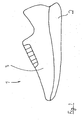
- a shoe 1 is sketched, which in a known manner a sole 2, on which a shoe upper 3 is arranged.
- a sole 2 on which a shoe upper 3 is arranged.
- the material of the shoe upper 3, ie the shaft material, is constructed in a special way. This goes out Fig. 2 to Fig. 4 out.
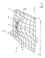
- the basic structure of the shaft material is a fabric structure 4 as shown in FIG Fig. 2 outlined.
- a fabric structure 4 as shown in FIG Fig. 2 outlined.
- the illustrated fabric structure 4 is formed by fabric threads 5, which are interwoven or hooked together.
- Fig. 3 is a preferred interweaving of the fabric threads 5 can be seen. It can be said that the fabric threads 5 extend substantially in two mutually perpendicular directions x and y. However, the fabric threads 5 do not form a planar structure, but the in Fig. 2 three-dimensional shape to be seen.
- Fig. 3 As can be seen, the fabric threads 5 are hooked together by a weaving process so that a grid-shaped surface is formed.
- the grid dimension b (s. Fig. 2 ) is typically in the range of 0.5 to 2 mm.
- elevations 10 is a plurality of parallel juxtaposed, ie parallel to each other in the x and y direction.
- the size of the structure is defined for the example described by a pitch a, where a is typically in the range between 5 to 20 mm, preferably 8 to 12 mm.
- a is typically in the range between 5 to 20 mm, preferably 8 to 12 mm.
- a fabric thread whose diameter is in the range between 0.03 to 0.1 mm.
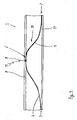
- the cover layer 8 contacts the fabric structure 4 only at certain points, ie the cover layer 8 rests only on the higher points 6 of the fabric structure 4.
- a welding energy input 17 takes place, for. B. by an ultrasonic welder or by a high frequency welding device, so that it comes to a fusion of the material of the fabric structure 4 and the material of the cover layer 8.
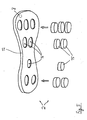
- the sole 2 consists of a base body 12, the structure of which is schematic Fig. 6 evident. Accordingly, reinforcing fibers 13, in particular carbon fibers, interwoven with one another are embedded in a plastic matrix or synthetic resin matrix 14, which preferably consists of epoxy resin. There is therefore a very strong and elastic structure for the main body 12th
- recesses 16 are introduced into the base plate 12, from which one in Fig. 5 the bottom looks.
- the shape of the recesses 16 corresponds to the shape of outsole elements 15 of rubber material, which in their entirety form the outsole of the shoe 1.
- the outsole elements 15 are inserted after the preparation of the base body 12 in the recesses 16; the depth of the recesses 16 is smaller than the height of the outsole elements 15, so that the outsole elements 15 after the insertion into the recesses 16 project down and so can perform their function as an outsole.
- a strong bond between the base body 12 and the outsole elements 15 is achieved by a vulcanization process, which is carried out after the placement of the outsole elements 15 in the base body 12 in a corresponding Vulkanisierform.
- FIGS. 7 to 9 An alternative embodiment of a sole 2 according to the invention can be seen.
- the sole also consists of a base body 12, on which outsole elements 15 are fastened.
- the outsole elements 15 are here, however, formed as cleats 15 ', which are fixed to the base body 12.
- the sectional view according to Fig. 8 (Cut CD according to Fig. 7 ) shows that - as already stated above - the material of the outsole element in the form of the stud 15 'is injection-molded or vulcanized directly on the base body 12 of the sole.
- the base body 12 has been converted in the region of the receptacle of the stud 15 'according to the shape of the negative something from the planar shape, so that the shape of the body 12 is formed, as it Fig. 8 shows.
- the material of the stud 15 ' is molded or vulcanized.
- a mechanical connection between body 12 and studs 15 ' is not present.
- the base body 12 is not formed as a continuous plate, but consists of two parts 12 'and 12 ".
- the two parts 12', 12" can be placed in a tool during production; then rubber material is placed over it so that the parts 12 ', 12 "of the main body are connected via the rubber material Fig. 7 a rubber bar 20 can be seen, over which the parts 12 'and 12 "are elastically connected to one another, so that at this point a flexible, articulated connection can be made between the parts 12', 12", which act as flex zones between the Parts 12 ', 12 “serves.
- the rubber material is used in the area of the rubber track 20 so as functional Element that interrupts the structure of the body 12 and makes the fiber reinforced plates relative to each other in a defined manner flexible.
- the rubber material as a rubber layer, the parts 12 ', 12 "contacted on one side .. In the edge region, the rubber material can be designed as a peripheral edge 19 (circumferential rubber lip).
- An alternative mode of production is based on the fact that the material of the base body 12 is introduced in not yet finally cured state in a tool to inject the material of the outsole member, but that the material of the base body 12 (in particular the carbon fiber material) is introduced into the tool , as well as prefabricated outsole elements or studs 15, 15 '.
- both the material of the body 12 is spent in its final state ready for use, at the same time the rubber material is connected to the material of the body 12.
Landscapes
- Engineering & Computer Science (AREA)
- Chemical & Material Sciences (AREA)
- Materials Engineering (AREA)
- Mechanical Engineering (AREA)
- Footwear And Its Accessory, Manufacturing Method And Apparatuses (AREA)
Description
- Die Erfindung betrifft einen Schuh, insbesondere einen Sportschuh, mit einer Sohle und einem mit der Sohle verbundenen Schuhoberteil, wobei die Sohle aufweist: mindestens einen der Form der Sohle entsprechenden Grundkörper, wobei der mindestens eine Grundkörper eine Vielzahl von Verstärkungsfasern aufweist, die in eine Kunststoff- oder Kunstharzmatrix eingelagert sind, und eine Anzahl Außensohlenelemente, wobei die Außensohlenelemente stoffschlüssig an dem mindestens einen Grundkörper befestigt sind.
- Einen Schuh dieser Art offenbart die
GB 2 256 784 A DE 42 14 802 A1 , in derUS 5 473 827 A und in derUS 2008/010863 A1 beschrieben. - Schuhe dieser üblichen Art müssen für bestimmte Anwendungsfälle besonders leicht sein. Dies gilt insbesondere für einen Sportschuh. Entsprechendes gilt auch vor allem für einen Fußballschuh, an den sowohl hohe Anforderungen an die Festigkeit und Steifigkeit gestellt werden, um die Funktionalität des Schuhs zu gewährleisten, als auch an das Gewicht, das regelmäßig möglichst gering sein sollte.
- Daher sind vielfältige Konzepte bekannt geworden, mit denen versucht wird, das Gewicht des Schuhs bei Aufrechterhaltung einer hinreichenden Steifigkeit möglichst zu reduzieren.
- Auch der Erfindung liegt die Aufgabe zugrunde, einen Schuh, insbesondere einen Sportschuh, der eingangs genannten Art so fortzubilden, dass er zwar einerseits eine hinreichende Steifigkeit aufweist und so die geforderte Funktionalität gewährleistet, dass er andererseits aber auch einen besonders leichten Aufbau hat.
- Die Lösung dieser Aufgabe durch die Erfindung ist dadurch gekennzeichnet, dass der mindestens eine Grundkörper Ausnehmungen für die Außensohlenelemente aufweist, wobei die Ausnehmungen der Form der Außensohlenelemente entsprechen, wobei die Außensohlenelemente aus Gummimaterial bestehen, wobei der stoffschlüssige Verbund zwischen dem mindestens einen Grundkörper und den Außensohlenelementen durch Vulkanisation hergestellt ist, wobei der Schuh frei von einer Zwischensohle ist und wobei oberhalb des mindestens einen Grundkörpers eine Innensohle eingeklebt ist.
- Die Verstärkungsfasern sind bevorzugt Kohlenstofffasern. Sie können in eine Epoxidharzmatrix eingelagert sein.
- Die Verstärkungsfasern können dabei zumindest teilweise miteinander verwoben sein.
- Eine Fortbildung sieht vor, dass der Grundkörper aus mindestens zwei Teilen gebildet ist, die über eine an beiden Teilen anvulkanisierte Gummischicht miteinander verbunden sind.
- Das Verfahren zum Herstellen der Sohle, welches nicht Teil der Erfindung ist, zeichnet sich durch die folgenden Schritte aus:
- a) Herstellen mindestens eines der Form der Sohle entsprechenden Grundkörpers, wobei der mindestens eine Grundkörper durch eine Vielzahl von Verstärkungsfasern gebildet wird, die in eine Kunststoff- oder Kunstharzmatrix eingelagert werden;
- b) Anordnen einer Anzahl Außensohlenelemente an den mindestens einen Grundkörper;
- c) Herstellen einer stoffschlüssigen Verbindung zwischen dem mindestens einen Grundkörper und den Außensohlenelementen durch Durchführen eines Vulkanisiervorgangs.
- Gemäß einer nicht beanspruchten Ausführungsform weist das Schuhoberteil auf:
- eine Gewebestruktur, die aus Gewebefäden besteht, wobei die Gewebestruktur als dreidimensionale Struktur ausgebildet ist, die eine Anzahl höher gelegener Punkte und eine Anzahl niedrig gelegener Punkte aufweist, und
- eine Deckschicht,
- Die Verbindung der Deckschicht ist bevorzugt durch eine Verschweißung, insbesondere durch eine Hochfrequenz- oder Ultraschallverschweißung, des Materials der Gewebestruktur mit dem Material der Deckschicht hergestellt.
- Die Gewebestruktur hat vorzugsweise eine Anzahl von hügel- oder höckerartig ausgebildeten Erhebungen, wobei die oberen Bereiche der hügel- oder höckerartigen Erhebungen die höher gelegenen Punkte aufweisen oder bilden. Die hügel- oder höckerartigen Erhebungen können in zwei zueinander senkrechten Richtungen parallel zueinander angeordnet sein. Sie können durch 7 bis 15 parallel zueinander verlaufende Gewebefäden gebildet werden, wobei diese vorzugsweise ineinander verwoben oder verhakt sind.
- Die Gewebefäden bestehen bevorzugt aus Polyethylenterephthalat, aus Polyamid oder aus Polyester. Die Deckschicht besteht indes bevorzugt aus einem Thermoplastischen Elastomer (TPE), insbesondere aus Thermoplastischem Elastomer auf Urethanbasis (TPU).
- Weiterbildungsgemäß ist eine zweite Deckschicht angeordnet, die mit den niedrig gelegenen Punkten der Gewebestruktur verbunden ist.
- Das vorgeschlagene Verfahren zum Herstellen des Materials für das Schuhoberteil zeichnet sich durch die Schritte aus:
- a) Bereitstellen einer Gewebestruktur, wobei die Gewebestruktur aus Gewebefäden hergestellt wird und wobei die Gewebestruktur als dreidimensionale Struktur ausgebildet wird, die eine Anzahl höher gelegener Punkte und eine Anzahl niedrig gelegener Punkte aufweist;
- b) Anordnen einer Deckschicht auf der Gewebestruktur, so dass zumindest teilweise Kontakt zwischen den höher gelegenen Punkten der Gewebestruktur und der Deckschicht besteht;
- c) Verbinden zumindest eines Teils der höher gelegenen Punkte der Gewebestruktur mit der Deckschicht durch einen Schweißvorgang.
- Der Schweißvorgang ist bevorzugt ein Hochfrequenzschweißvorgang oder ein Ultraschallschweißvorgang.
- Die vorgeschlagene Konzeption stellt bei der Herstellung des Schaftmaterials für das Schuhoberteil also auf eine dreidimensional ausgebildete Gewebestruktur, vorzugsweise mit einer Vielzahl von Höckern, ab. Auf diese Struktur wird eine flächige Bahn (Folie) vorzugsweise aus TPU aufgelegt. Mittels eines wärmeerzeugenden Elements (z. B. Hochfrequenzelektrode oder Ultraschallelektrode) wird die Folie mit den Höckerspitzen verschweißt. Demgemäß wird die Folie punktuell mit der Gewebestruktur verbunden.
- Dieser Verbund wird als Schaftmaterial für Sportschuhe, insbesondere für Fußballschuhe, eingesetzt.
- Der Vorteil ist eine sehr gute Lüftung des Schuhs, da die dreidimensional ausgebildete Textilstruktur gut luftleitend ist, da sie hierfür eine Kanalstruktur schafft. Das Material nimmt kein Wasser auf. Es ist sehr leicht, somit ist auch der Schuh "superleicht", der aus diesem Schaftmaterial hergestellt ist. Verstärkungsmaterialien im Schaftmaterial sind überflüssig.
- Bezüglich der vorgeschlagenen Sohlenstruktur gilt, dass auch diese in besonders vorteilhafter Weise für Fußballschuhe eingesetzt werden kann, da die Sohlengrundplatte - insbesondere als Kohlenstofffaserplatte ausgebildet - eine hohe Steifigkeit hat. Die vorgeformten Gummielemente, die als Außensohle fungieren, haben dadurch, dass sie anvulkanisiert sind, einen festen Verbund mit der Grundplatte.
- Die vorgeformten Gummielemente werden bei der Herstellung der Sohle in eine Vulkanisierform eingelegt, ebenso die Grundplatte (Grundkörper). Dann erfolgt der Verbindungsprozess durch Vulkanisieren. Möglich ist es auch, dass mehrere Teile den Grundkörper bilden; diese Teile werden dann ins Werkzeug positioniert eingelegt und mit Gummimaterial verbunden.
- Bei der Grundplatte handelt es sich bevorzugt um eine Platte, die verwebte Kohlenstofffasern aufweist, die in einer Kunststoff- oder Kunstharzmatrix eingelagert sind (z. B. in eine aus Epoxidharz).
- Bei einem Fußballschuh kann diese so hergestellte Sohle ohne Zwischensohle eingesetzt werden. Es kommt zu einer günstigen Druckverteilung infolge der hohen Steifigkeit der Grundplatte. Die Konstruktion ist sehr leicht. Dies ermöglicht wiederum einen "superleichten" Schuh.
- Besonders vorteilhaft ist es, wenn das vorgeschlagene Schaftmaterial des Schuhoberteils und die vorgeschlagene Sohle kombiniert werden. Dann ergibt sich ein besonders leichter Schuh mit hoher Festigkeit.
- In der Zeichnung ist ein Ausführungsbeispiel der Erfindung dargestellt. Es zeigen:
- Fig. 1
- einen Schuh in der Seitenansicht,
- Fig. 2
- eine perspektivische Ansicht einer Gewebestruktur, die Bestandteil des Materials des Schuhoberteils ist,
- Fig. 3
- eine Darstellung der Aufbaus der Gewebestruktur gemäß
Fig. 2 , - Fig. 4
- eine Schnittdarstellung durch das Material des Schuhoberteils gemäß dem Schnitt A-B gemäß
Fig. 2 , - Fig. 5
- eine schematische Explosionsdarstellung der Sohle des vorgeschlagenen Schuhs, die die Bestandteile der Sohle zeigt, und
- Fig. 6
- schematisch die Vergrößerung "Z" gemäß
Fig. 5 , die den Aufbau einer Grundplatte der Sohle des Schuhs zeigt, - Fig. 7
- die Draufsicht auf die Unterseite einer Sohle gemäß einer alternativen Ausführungsform der Erfindung, wobei hier die Sohle mit einer Anzahl Stollenelemente versehen ist,
- Fig. 8
- den Schnitt C-D gemäß
Fig. 7 und - Fig. 9
- den Schnitt E-F gemäß
Fig. 7 . - In
Fig. 1 ist ein Schuh 1 skizziert, der in bekannter Weise eine Sohle 2 aufweist, an der ein Schuhoberteil 3 angeordnet ist. Für die Verbindung der Sohle 2 mit dem Schuhoberteil 3 gibt es mannigfaltige vorbekannte Möglichkeiten, auf die hier nicht eingegangen werden muss. - Das Material des Schuhoberteils 3, d. h. das Schaftmaterial, ist in spezieller Weise aufgebaut. Dies geht aus
Fig. 2 bis Fig. 4 hervor. - Die Grundstruktur des Schaftmaterials ist eine Gewebestruktur 4, wie sie in
Fig. 2 skizziert ist. Hier ist nur ein kleiner Ausschnitt der Gewebestruktur 4 zu sehen, nämlich ein Ausschnitt, der eine einzige hügel- oder höckerartig ausgebildete Erhebung 10 aufweist. - Gebildet wird die dargestellte Gewebestruktur 4 durch Gewebefäden 5, die miteinander verwoben bzw. verhakt sind. In
Fig. 3 ist eine bevorzugte Verflechtung der Gewebefäden 5 zu sehen. Man kann sagen, dass die Gewebefäden 5 sich im wesentlichen in zwei zueinander senkrechte Richtungen x und y erstrecken. Dabei bilden die Gewebefäden 5 allerdings keine ebene Struktur, sondern die inFig. 2 zu sehende dreidimensionale Form. - Wie aus
Fig. 3 hervorgeht, sind die Gewebefäden 5 durch einen Webevorgang so miteinander verhakt, dass eine gitterförmige Oberfläche entsteht. Das Gittermaß b (s.Fig. 2 ) liegt typischerweise im Bereich von 0,5 bis 2 mm. - Von der in
Fig. 2 skizzierten Erhebungen 10 ist eine Vielzahl parallel nebeneinander angeordnet, d. h. parallel nebeneinander in x- und in y-Richtung. Die Größe der Struktur ist für den beschriebenen Beispielsfall durch ein Rastermaß a definiert, wobei a typischerweise im Bereich zwischen 5 bis 20 mm liegt, vorzugsweise bei 8 bis 12 mm. Bevorzugt eingesetzt wird ein Gewebefaden, dessen Durchmesser im Bereich zwischen 0,03 bis 0,1 mm liegt. - Durch die dreidimensionale Ausgestaltung der Gewebestruktur 4 ergibt sich, wie in der Zusammenschau der
Figuren 2 und3 gesehen werden kann, pro Erhebung ein höher gelegener Punkt 6 sowie niedrig gelegene Punkte 7. Das Schaftmaterial wird nun dadurch gebildet, dass auf die Oberseite der Gewebstruktur 4 eine Deckschicht 8 aufgelegt wird, die im Ausführungsbeispiel aus einer dünnen, ebenen Schicht besteht. - Demgemäß kontaktiert die Deckschicht 8 die Gewebestruktur 4 nur punktuell, d. h. die Deckschicht 8 liegt nur an den höher gelegenen Punkten 6 der Gewebestruktur 4 an. Schematisch ist in
Fig. 4 angedeutet, dass nunmehr, nachdem die Deckschicht 8 platziert ist, ein Schweißenergieeintrag 17 erfolgt, z. B. durch ein Ultraschallschweißgerät oder durch ein Hochfrequenzschweißgerät, so dass es zu einem Verschmelzen des Materials der Gewebestruktur 4 und des Materials der Deckschicht 8 kommt. Dies ist inFig. 4 durch die Verbindung 9 in Form eines Schweißpunktes angedeutet. - In analoger Weise kann auf der Unterseite der Gewebestruktur vorgegangen werden. Hier kann - wie in
Fig. 4 zu sehen - eine zweite Deckschicht 11 angelegt werden, die in gleicher Weise über Schweißpunkte befestigt werden kann. - Hierdurch ergibt sich eine sehr stabile und dennoch sehr leichte Materialstruktur zur Verwendung als Schaftmaterial für das Schuhoberteil.
- In
Fig. 5 ist zu sehen, wie die vorgeschlagene zugehörige Sohle 2 des Schuhs 1 konzipiert ist. Die Sohle 2 besteht aus einem Grundkörper 12, dessen Aufbau schematisch ausFig. 6 hervorgeht. Demgemäß sind Verstärkungsfasern 13, insbesondere Kohlenstofffasern, miteinander verwoben in eine Kunststoffmatrix oder Kunstharzmatrix 14 eingelagert, die bevorzugt aus Epoxidharz besteht. Es ergibt sich daher eine sehr feste und elastische Struktur für den Grundkörper 12. - Bereits bei der Formung des Grundkörpers 12, gegebenenfalls aber auch erst später durch mechanische Bearbeitung, werden Ausnehmungen 16 in die Grundplatte 12 eingebracht, von der man in
Fig. 5 die Unterseite sieht. Die Form der Ausnehmungen 16 entspricht der Form von Außensohlenelementen 15 aus Gummimaterial, die in ihrer Gesamtheit die Außensohle des Schuhs 1 bilden. - Die Außensohlenelemente 15 werden nach der Herstellung des Grundkörpers 12 in die Ausnehmungen 16 eingeschoben; die Tiefe der Ausnehmungen 16 ist dabei kleiner als die Höhe der Außensohlenelemente 15, so dass die Außensohlenelemente 15 nach dem Einsetzen in die Ausnehmungen 16 nach unten überstehen und so ihre Funktion als Außensohle wahrnehmen können.
- Ein fester Verbund zwischen dem Grundkörper 12 und den Außensohlenelementen 15 wird durch einen Vulkanisiervorgang erreicht, der nach der Platzierung der Außensohlenelemente 15 im Grundkörper 12 in einer entsprechenden Vulkanisierform ausgeführt wird.
- In den
Figuren 7 bis 9 ist eine alternative Ausführungsform einer Sohle 2 gemäß der Erfindung zu sehen. - Grundsätzlich gilt auch hier, dass die Sohle aus einem Grundkörper 12 besteht, an dem Außensohlenelemente 15 befestigt sind. Die Außensohlenelemente 15 sind hier allerdings als Stollen 15' ausgebildet, die am Grundkörper 12 befestigt sind. Die Schnittdarstellung gemäß
Fig. 8 (Schnitt C-D gemäßFig. 7 ) zeigt, dass - wie vorstehend bereits ausgeführt - das Material des Außensohlenelements in Form des Stollens 15' direkt am Grundkörper 12 der Sohle angespritzt bzw. anvulkanisiert ist. WieFig. 8 entnommen werden kann, ist der Grundkörper 12 im Bereich der Aufnahme des Stollens 15' entsprechend der Form des Negativs etwas aus der ebenen Form umgeformt worden, so dass die Form des Grundkörpers 12 entsteht, wie esFig. 8 zeigt. An die ausgeformte Erhebung ist das Material des Stollens 15' angespritzt bzw. anvulkanisiert. Eine mechanische Verbindung zwischen Grundkörper 12 und Stollen 15' ist nicht vorhanden. Insbesondere weist der Grundkörper 12 im Bereich der Aufnahme des Stollens 15' keine Ausnehmung auf. Demgemäß liegt eine durchgängige Schicht des faserverstärkten Materials des Grundkörpers 12 vor. - Eine andere spezifische Ausgestaltung des Ausführungsbeispiels gemäß
Fig. 7 ist, dass hier der Grundkörper 12 nicht als eine durchgängige Platte ausgebildet ist, sondern aus zwei Teilen 12' und 12" besteht. Die beiden Teile 12', 12" können bei der Fertigung in ein Werkzeug positioniert eingelegt werden; dann wird Gummimaterial so darübergelegt, dass die Teile 12', 12" des Grundkörpers über das Gummimaterial verbunden werden. InFig. 7 ist ein Gummisteg 20 zu sehen, über den die Teile 12' und 12" miteinander elastisch verbunden sind. So kann an dieser Stelle eine flexible, gelenkartige Verbindung zwischen den Teilen 12', 12" hergestellt werden, die als Flexzone bzw. Flexrille zwischen den Teilen 12', 12" dient. Das Gummimaterial dient im Bereich des Gummistegs 20 also als funktionelles Element, das die Struktur des Grundkörpers 12 unterbricht und die faserverstärkten Platten relativ zueinander in definierter Weise flexibel macht. - Dem Schnitt E-F gemäß
Fig. 9 ist zu entnehmen, dass das Gummimaterial als Gummischicht die Teile 12', 12" einseitig kontaktiert. Im Randbereich kann das Gummimaterial als umlaufender Rand 19 (umlaufende Gummilippe) ausgeführt sein. - Eine alternative Produktionsweise stellt darauf ab, dass das Material des Grundkörpers 12 in noch nicht endgültig fertig ausgehärtetem Zustand in ein Werkzeug eingebracht wird, um das Material des Außensohlenelements anzuspritzen, sondern dass das Material des Grundkörpers 12 (insbesondere das Kohlefasermaterial) in das Werkzeug eingebracht wird, genauso wie vorgefertigte Außensohlenelemente bzw. Stollen 15, 15'.
- Im Rahmen eines Vulkanisierungsprozesses wird dann sowohl das Material des Grundkörpers 12 in seinen endgültigen gebrauchsfertigen Zustand verbracht, gleichzeitig wird das Gummimaterial mit dem Material des Grundkörpers 12 verbunden.
-
- 1
- Schuh
- 2
- Sohle
- 3
- Schuhoberteil
- 4
- Gewebestruktur
- 5
- Gewebefaden
- 6
- höher gelegener Punkt
- 7
- niedrig gelegener Punkt
- 8
- Deckschicht
- 9
- Verbindung (Verschweißung)
- 10
- hügel- oder höckerartig ausgebildete Erhebungen
- 11
- zweite Deckschicht
- 12
- Grundkörper
- 12'
- erster Teil des Grundkörpers
- 12"
- zweiter Teil der Grundkörpers
- 13
- Verstärkungsfaser
- 14
- Kunststoffmatrix / Kunstharzmatrix
- 15
- Außensohlenelement
- 15'
- Stollen
- 16
- Ausnehmung
- 17
- Schweißenergieeintrag
- 18
- Gummischicht
- 19
- umlaufender Rand
- 20
- Gummisteg
- x
- Richtung
- y
- Richtung
- a
- Rastermaß
- b
- Gittermaß
Claims (4)
- Schuh (1), insbesondere Sportschuh, mit einer Sohle (2) und einem mit der Sohle (2) verbundenen Schuhoberteil (3), wobei die Sohle (2) aufweist:- mindestens einen der Form der Sohle (2) entsprechenden Grundkörper (12, 12', 12"), wobei der mindestens eine Grundkörper (12, 12', 12") eine Vielzahl von Verstärkungsfasern (13) aufweist, die in eine Kunststoff- oder Kunstharzmatrix (14) eingelagert sind, und- eine Anzahl Außensohlenelemente (15, 15'), wobei die Außensohlenelemente (15, 15') stoffschlüssig an dem mindestens einen Grundkörper (12, 12', 12") befestigt sind,dadurch gekennzeichnet, dass
der mindestens eine Grundkörper (12, 12', 12") Ausnehmungen (16) für die Außensohlenelemente (15) aufweist, wobei die Ausnehmungen (16) der Form der Außensohlenelemente (15) entsprechen,
wobei die Außensohlenelemente (15, 15') aus Gummimaterial bestehen, wobei der stoffschlüssige Verbund zwischen dem mindestens einen Grundkörper (12, 12', 12") und den Außensohlenelementen (15, 15') durch Vulkanisation hergestellt ist,
wobei der Schuh frei von einer Zwischensohle ist und
wobei oberhalb des mindestens einen Grundkörpers (12, 12', 12") eine Innensohle eingeklebt ist. - Schuh nach Anspruch 1, dadurch gekennzeichnet, dass die Verstärkungsfasern (13) Kohlenstöfffasern sind, wobei die Verstärkungsfasern (13) vorzugsweise in eine Epoxidharzmatrix eingelagert sind.
- Schuh nach Anspruch 1 oder 2, dadurch gekennzeichnet, dass die Verstärkungsfasern (13) zumindest teilweise miteinander verwoben sind.
- Schuh nach einem der Ansprüche 1 bis 3, dadurch gekennzeichnet, dass der Grundkörper (12) aus mindestens zwei Teilen (12', 12") gebildet ist, die über eine an beiden Teilen (12', 12") anvulkanisierte Gummischicht miteinander verbunden sind.
Applications Claiming Priority (2)
| Application Number | Priority Date | Filing Date | Title |
|---|---|---|---|
| DE102010055818A DE102010055818A1 (de) | 2010-12-23 | 2010-12-23 | Schuh, insbesondere Sportschuh, und Verfahren zum Herstellen eines Schuhs |
| PCT/EP2011/006196 WO2012084137A1 (de) | 2010-12-23 | 2011-12-09 | Schuh, insbesondere sportschuh, und verfahren zum herstellen eines schuhs |
Publications (2)
| Publication Number | Publication Date |
|---|---|
| EP2654481A1 EP2654481A1 (de) | 2013-10-30 |
| EP2654481B1 true EP2654481B1 (de) | 2015-05-20 |
Family
ID=45319061
Family Applications (1)
| Application Number | Title | Priority Date | Filing Date |
|---|---|---|---|
| EP20110794411 Active EP2654481B1 (de) | 2010-12-23 | 2011-12-09 | Schuh, insbesondere sportschuh |
Country Status (7)
| Country | Link |
|---|---|
| US (1) | US20130340290A1 (de) |
| EP (1) | EP2654481B1 (de) |
| JP (1) | JP2014500108A (de) |
| CN (1) | CN103313620A (de) |
| DE (1) | DE102010055818A1 (de) |
| ES (1) | ES2544829T3 (de) |
| WO (1) | WO2012084137A1 (de) |
Families Citing this family (10)
| Publication number | Priority date | Publication date | Assignee | Title |
|---|---|---|---|---|
| US9775401B2 (en) | 2015-01-16 | 2017-10-03 | Nike, Inc. | Sole system for an article of footwear incorporating a knitted component with a one-piece knit outsole |
| US10568383B2 (en) | 2015-01-16 | 2020-02-25 | Nike, Inc. | Sole system for an article of footwear incorporating a knitted component with a one-piece knit outsole and a tensile element |
| US9848673B2 (en) | 2015-01-16 | 2017-12-26 | Nike, Inc. | Vacuum formed knit sole system for an article of footwear incorporating a knitted component |
| US9820530B2 (en) | 2015-01-16 | 2017-11-21 | Nike, Inc. | Knit article of footwear with customized midsole and customized cleat arrangement |
| CN105747383A (zh) * | 2016-03-31 | 2016-07-13 | 海门鼎诚鞋业有限公司 | 一种鞋的胶粘工艺 |
| CN107080325A (zh) * | 2017-06-06 | 2017-08-22 | 中山市富达运动器材有限公司 | 一种足球钉鞋底 |
| USD872983S1 (en) * | 2018-06-20 | 2020-01-21 | Christian Louboutin | Sole for footwear |
| CN112293855A (zh) * | 2019-07-23 | 2021-02-02 | 东莞市臻灏贸易有限公司 | 一种防滑鞋底及其制造工艺 |
| USD1069379S1 (en) | 2023-03-13 | 2025-04-08 | Amazon Technologies, Inc. | Footwear |
| USD1069380S1 (en) | 2023-03-13 | 2025-04-08 | Amazon Technologies, Inc. | Footwear |
Family Cites Families (16)
| Publication number | Priority date | Publication date | Assignee | Title |
|---|---|---|---|---|
| ES8704337A1 (es) * | 1984-11-07 | 1987-04-01 | Kloeckner Ferromatik Desma | Procedimiento y dispositivo para fabricar zapatos de deportecon suela moldeada e inyectada en la plantilla |
| JPS62116905U (de) * | 1986-01-17 | 1987-07-24 | ||
| JPH0777562B2 (ja) * | 1991-02-08 | 1995-08-23 | 美津濃株式会社 | インサート補強部材及びインサート補強部材を有する靴底 |
| US5617653A (en) * | 1991-04-15 | 1997-04-08 | Andrew S. Walker | Break-away cleat assembly for athletic shoe |
| TW228469B (de) * | 1991-06-19 | 1994-08-21 | Uhl Sportartikel Karl | |
| FR2681515B1 (fr) * | 1991-09-19 | 1993-12-24 | Patrick Int | Semelage a protuberances pour chaussures de sport. |
| DE4214802A1 (de) * | 1992-05-04 | 1993-11-11 | Uhl Sportartikel Karl | Schuhsohle, insbesondere für Sportschuhe und Sicherheitsschuhe |
| CN1066620C (zh) * | 1992-06-19 | 2001-06-06 | 铃木总业株式会社 | 凹凸成形层及其制造方法 |
| CN1104214C (zh) * | 1994-05-18 | 2003-04-02 | 住友橡胶工业株式会社 | 鞋底 |
| JP3392395B2 (ja) * | 2000-07-18 | 2003-03-31 | 美津濃株式会社 | 靴 底 |
| US6973746B2 (en) * | 2003-07-25 | 2005-12-13 | Nike, Inc. | Soccer shoe having independently supported lateral and medial sides |
| US7249428B1 (en) * | 2004-07-27 | 2007-07-31 | Gary Burella | Universal footwear including removable cleats |
| US7832117B2 (en) * | 2006-07-17 | 2010-11-16 | Nike, Inc. | Article of footwear including full length composite plate |
| WO2009062030A1 (en) * | 2007-11-07 | 2009-05-14 | Linckia Development Llc | Footware suspension system |
| JP4388580B2 (ja) * | 2008-03-28 | 2009-12-24 | 美津濃株式会社 | スポーツ用シューズのインソール構造体 |
| US8763276B2 (en) * | 2011-03-01 | 2014-07-01 | Nike, Inc. | Removable outsole elements for articles of footwear |
-
2010
- 2010-12-23 DE DE102010055818A patent/DE102010055818A1/de not_active Withdrawn
-
2011
- 2011-12-09 US US13/996,713 patent/US20130340290A1/en not_active Abandoned
- 2011-12-09 WO PCT/EP2011/006196 patent/WO2012084137A1/de not_active Ceased
- 2011-12-09 ES ES11794411.6T patent/ES2544829T3/es active Active
- 2011-12-09 CN CN2011800624902A patent/CN103313620A/zh active Pending
- 2011-12-09 EP EP20110794411 patent/EP2654481B1/de active Active
- 2011-12-09 JP JP2013545080A patent/JP2014500108A/ja active Pending
Also Published As
| Publication number | Publication date |
|---|---|
| US20130340290A1 (en) | 2013-12-26 |
| EP2654481A1 (de) | 2013-10-30 |
| ES2544829T3 (es) | 2015-09-04 |
| WO2012084137A1 (de) | 2012-06-28 |
| JP2014500108A (ja) | 2014-01-09 |
| CN103313620A (zh) | 2013-09-18 |
| DE102010055818A1 (de) | 2012-06-28 |
Similar Documents
| Publication | Publication Date | Title |
|---|---|---|
| DE102010055818A1 (de) | Schuh, insbesondere Sportschuh, und Verfahren zum Herstellen eines Schuhs | |
| DE102014219918B4 (de) | Sohle für einen Schuh | |
| EP2654483B1 (de) | Schuh, insbesondere sportschuh, und verfahren zum herstellen eines schuhs | |
| DE102015204268B4 (de) | Sohlen für Sportschuhe, sowie deren Herstellung | |
| DE69203554T2 (de) | Profilierte Sohle für Athletikschuhe. | |
| EP0993259B1 (de) | Dünne, flexible schuh-laufsohle mit durchgespritzten trittelementen, verfahren zur herstellung einer solchen laufsohle und mit einer solchen laufsohle versehener schuh | |
| DE4120136C2 (de) | Schuhsohle, insbesondere Sportschuhsohle | |
| DE102018105628B4 (de) | Solenstruktur für Schuhe und Schuh mit der Sohlenstruktur | |
| DE102018122832B4 (de) | Sohlenstruktur für Schuhe und Schuhe mit dieser Sohlenstruktur | |
| WO2002000051A1 (de) | Als zwischensohle, innensohle oder einlegesohle ausgebildete sohle für einen schuh und schuh mit einer derartigen sohle | |
| DE102009028627A1 (de) | Außensohle und Sportschuh | |
| EP1602294B1 (de) | Polyurethan-Schaum-Einlegesohle und Verfahren zu ihrer Herstellung | |
| DE102018219185B4 (de) | Schuh, insbesondere ein Sportschuh | |
| EP1094729B1 (de) | Schuh-innensohle | |
| DE102020130010A1 (de) | Verfahren zur Herstellung einer Sohle eines Fußbekleidungsartikels | |
| DE102021107751A1 (de) | Sohlenkonstruktion für einen schuh, schuh mit derselben und verfahren zur herstellung derselben | |
| DE102020124000A1 (de) | Schuhoberteil und Schuh | |
| DE102023105735A1 (de) | Stollen für eine laufsohle, laufsohle für einen stollenschuh, verfahren zur herstellung einer laufsohle und stollenschuh | |
| DE102023201065A1 (de) | Außensohle für einen Schuh | |
| DE4214802A1 (de) | Schuhsohle, insbesondere für Sportschuhe und Sicherheitsschuhe | |
| DE102024129777A1 (de) | Sohlenserie und Verfahren zur Herstellung einer Sohle | |
| EP0857435B1 (de) | Sohle für Sportschuhe | |
| DE102023109071A1 (de) | Sohlenstruktur und tennisschuh umfassend die sohlenstruktur | |
| WO1997046125A2 (de) | Schuh und verfahren zu dessen herstellung sowie verwendung desselben | |
| DE3005077A1 (de) | Sohle, insbesondere fuer sportschuhe |
Legal Events
| Date | Code | Title | Description |
|---|---|---|---|
| PUAI | Public reference made under article 153(3) epc to a published international application that has entered the european phase |
Free format text: ORIGINAL CODE: 0009012 |
|
| 17P | Request for examination filed |
Effective date: 20130723 |
|
| AK | Designated contracting states |
Kind code of ref document: A1 Designated state(s): AL AT BE BG CH CY CZ DE DK EE ES FI FR GB GR HR HU IE IS IT LI LT LU LV MC MK MT NL NO PL PT RO RS SE SI SK SM TR |
|
| DAX | Request for extension of the european patent (deleted) | ||
| GRAP | Despatch of communication of intention to grant a patent |
Free format text: ORIGINAL CODE: EPIDOSNIGR1 |
|
| INTG | Intention to grant announced |
Effective date: 20150205 |
|
| GRAS | Grant fee paid |
Free format text: ORIGINAL CODE: EPIDOSNIGR3 |
|
| GRAA | (expected) grant |
Free format text: ORIGINAL CODE: 0009210 |
|
| AK | Designated contracting states |
Kind code of ref document: B1 Designated state(s): AL AT BE BG CH CY CZ DE DK EE ES FI FR GB GR HR HU IE IS IT LI LT LU LV MC MK MT NL NO PL PT RO RS SE SI SK SM TR |
|
| REG | Reference to a national code |
Ref country code: GB Ref legal event code: FG4D Free format text: NOT ENGLISH |
|
| REG | Reference to a national code |
Ref country code: CH Ref legal event code: EP |
|
| REG | Reference to a national code |
Ref country code: AT Ref legal event code: REF Ref document number: 727259 Country of ref document: AT Kind code of ref document: T Effective date: 20150615 |
|
| REG | Reference to a national code |
Ref country code: IE Ref legal event code: FG4D Free format text: LANGUAGE OF EP DOCUMENT: GERMAN |
|
| REG | Reference to a national code |
Ref country code: DE Ref legal event code: R096 Ref document number: 502011006898 Country of ref document: DE Effective date: 20150702 |
|
| REG | Reference to a national code |
Ref country code: ES Ref legal event code: FG2A Ref document number: 2544829 Country of ref document: ES Kind code of ref document: T3 Effective date: 20150904 |
|
| REG | Reference to a national code |
Ref country code: LT Ref legal event code: MG4D |
|
| REG | Reference to a national code |
Ref country code: NL Ref legal event code: MP Effective date: 20150520 |
|
| PG25 | Lapsed in a contracting state [announced via postgrant information from national office to epo] |
Ref country code: HR Free format text: LAPSE BECAUSE OF FAILURE TO SUBMIT A TRANSLATION OF THE DESCRIPTION OR TO PAY THE FEE WITHIN THE PRESCRIBED TIME-LIMIT Effective date: 20150520 Ref country code: NO Free format text: LAPSE BECAUSE OF FAILURE TO SUBMIT A TRANSLATION OF THE DESCRIPTION OR TO PAY THE FEE WITHIN THE PRESCRIBED TIME-LIMIT Effective date: 20150820 Ref country code: PT Free format text: LAPSE BECAUSE OF FAILURE TO SUBMIT A TRANSLATION OF THE DESCRIPTION OR TO PAY THE FEE WITHIN THE PRESCRIBED TIME-LIMIT Effective date: 20150921 Ref country code: LT Free format text: LAPSE BECAUSE OF FAILURE TO SUBMIT A TRANSLATION OF THE DESCRIPTION OR TO PAY THE FEE WITHIN THE PRESCRIBED TIME-LIMIT Effective date: 20150520 Ref country code: FI Free format text: LAPSE BECAUSE OF FAILURE TO SUBMIT A TRANSLATION OF THE DESCRIPTION OR TO PAY THE FEE WITHIN THE PRESCRIBED TIME-LIMIT Effective date: 20150520 |
|
| PG25 | Lapsed in a contracting state [announced via postgrant information from national office to epo] |
Ref country code: LV Free format text: LAPSE BECAUSE OF FAILURE TO SUBMIT A TRANSLATION OF THE DESCRIPTION OR TO PAY THE FEE WITHIN THE PRESCRIBED TIME-LIMIT Effective date: 20150520 Ref country code: IS Free format text: LAPSE BECAUSE OF FAILURE TO SUBMIT A TRANSLATION OF THE DESCRIPTION OR TO PAY THE FEE WITHIN THE PRESCRIBED TIME-LIMIT Effective date: 20150920 Ref country code: RS Free format text: LAPSE BECAUSE OF FAILURE TO SUBMIT A TRANSLATION OF THE DESCRIPTION OR TO PAY THE FEE WITHIN THE PRESCRIBED TIME-LIMIT Effective date: 20150520 Ref country code: BG Free format text: LAPSE BECAUSE OF FAILURE TO SUBMIT A TRANSLATION OF THE DESCRIPTION OR TO PAY THE FEE WITHIN THE PRESCRIBED TIME-LIMIT Effective date: 20150820 Ref country code: GR Free format text: LAPSE BECAUSE OF FAILURE TO SUBMIT A TRANSLATION OF THE DESCRIPTION OR TO PAY THE FEE WITHIN THE PRESCRIBED TIME-LIMIT Effective date: 20150821 |
|
| REG | Reference to a national code |
Ref country code: FR Ref legal event code: PLFP Year of fee payment: 5 |
|
| PG25 | Lapsed in a contracting state [announced via postgrant information from national office to epo] |
Ref country code: EE Free format text: LAPSE BECAUSE OF FAILURE TO SUBMIT A TRANSLATION OF THE DESCRIPTION OR TO PAY THE FEE WITHIN THE PRESCRIBED TIME-LIMIT Effective date: 20150520 Ref country code: DK Free format text: LAPSE BECAUSE OF FAILURE TO SUBMIT A TRANSLATION OF THE DESCRIPTION OR TO PAY THE FEE WITHIN THE PRESCRIBED TIME-LIMIT Effective date: 20150520 |
|
| REG | Reference to a national code |
Ref country code: DE Ref legal event code: R097 Ref document number: 502011006898 Country of ref document: DE |
|
| PG25 | Lapsed in a contracting state [announced via postgrant information from national office to epo] |
Ref country code: PL Free format text: LAPSE BECAUSE OF FAILURE TO SUBMIT A TRANSLATION OF THE DESCRIPTION OR TO PAY THE FEE WITHIN THE PRESCRIBED TIME-LIMIT Effective date: 20150520 Ref country code: RO Free format text: LAPSE BECAUSE OF NON-PAYMENT OF DUE FEES Effective date: 20150520 Ref country code: CZ Free format text: LAPSE BECAUSE OF FAILURE TO SUBMIT A TRANSLATION OF THE DESCRIPTION OR TO PAY THE FEE WITHIN THE PRESCRIBED TIME-LIMIT Effective date: 20150520 Ref country code: SK Free format text: LAPSE BECAUSE OF FAILURE TO SUBMIT A TRANSLATION OF THE DESCRIPTION OR TO PAY THE FEE WITHIN THE PRESCRIBED TIME-LIMIT Effective date: 20150520 |
|
| PLBE | No opposition filed within time limit |
Free format text: ORIGINAL CODE: 0009261 |
|
| STAA | Information on the status of an ep patent application or granted ep patent |
Free format text: STATUS: NO OPPOSITION FILED WITHIN TIME LIMIT |
|
| 26N | No opposition filed |
Effective date: 20160223 |
|
| PG25 | Lapsed in a contracting state [announced via postgrant information from national office to epo] |
Ref country code: SI Free format text: LAPSE BECAUSE OF FAILURE TO SUBMIT A TRANSLATION OF THE DESCRIPTION OR TO PAY THE FEE WITHIN THE PRESCRIBED TIME-LIMIT Effective date: 20150520 Ref country code: BE Free format text: LAPSE BECAUSE OF NON-PAYMENT OF DUE FEES Effective date: 20151231 |
|
| PG25 | Lapsed in a contracting state [announced via postgrant information from national office to epo] |
Ref country code: MC Free format text: LAPSE BECAUSE OF FAILURE TO SUBMIT A TRANSLATION OF THE DESCRIPTION OR TO PAY THE FEE WITHIN THE PRESCRIBED TIME-LIMIT Effective date: 20150520 Ref country code: LU Free format text: LAPSE BECAUSE OF FAILURE TO SUBMIT A TRANSLATION OF THE DESCRIPTION OR TO PAY THE FEE WITHIN THE PRESCRIBED TIME-LIMIT Effective date: 20151209 |
|
| REG | Reference to a national code |
Ref country code: CH Ref legal event code: PL |
|
| REG | Reference to a national code |
Ref country code: IE Ref legal event code: MM4A |
|
| PG25 | Lapsed in a contracting state [announced via postgrant information from national office to epo] |
Ref country code: LI Free format text: LAPSE BECAUSE OF NON-PAYMENT OF DUE FEES Effective date: 20151231 Ref country code: IE Free format text: LAPSE BECAUSE OF NON-PAYMENT OF DUE FEES Effective date: 20151209 Ref country code: CH Free format text: LAPSE BECAUSE OF NON-PAYMENT OF DUE FEES Effective date: 20151231 |
|
| REG | Reference to a national code |
Ref country code: FR Ref legal event code: PLFP Year of fee payment: 6 |
|
| PG25 | Lapsed in a contracting state [announced via postgrant information from national office to epo] |
Ref country code: SM Free format text: LAPSE BECAUSE OF FAILURE TO SUBMIT A TRANSLATION OF THE DESCRIPTION OR TO PAY THE FEE WITHIN THE PRESCRIBED TIME-LIMIT Effective date: 20150520 Ref country code: HU Free format text: LAPSE BECAUSE OF FAILURE TO SUBMIT A TRANSLATION OF THE DESCRIPTION OR TO PAY THE FEE WITHIN THE PRESCRIBED TIME-LIMIT; INVALID AB INITIO Effective date: 20111209 |
|
| PG25 | Lapsed in a contracting state [announced via postgrant information from national office to epo] |
Ref country code: NL Free format text: LAPSE BECAUSE OF FAILURE TO SUBMIT A TRANSLATION OF THE DESCRIPTION OR TO PAY THE FEE WITHIN THE PRESCRIBED TIME-LIMIT Effective date: 20150520 Ref country code: CY Free format text: LAPSE BECAUSE OF FAILURE TO SUBMIT A TRANSLATION OF THE DESCRIPTION OR TO PAY THE FEE WITHIN THE PRESCRIBED TIME-LIMIT Effective date: 20150520 Ref country code: SE Free format text: LAPSE BECAUSE OF FAILURE TO SUBMIT A TRANSLATION OF THE DESCRIPTION OR TO PAY THE FEE WITHIN THE PRESCRIBED TIME-LIMIT Effective date: 20150520 |
|
| PG25 | Lapsed in a contracting state [announced via postgrant information from national office to epo] |
Ref country code: MT Free format text: LAPSE BECAUSE OF FAILURE TO SUBMIT A TRANSLATION OF THE DESCRIPTION OR TO PAY THE FEE WITHIN THE PRESCRIBED TIME-LIMIT Effective date: 20150520 |
|
| REG | Reference to a national code |
Ref country code: FR Ref legal event code: PLFP Year of fee payment: 7 |
|
| REG | Reference to a national code |
Ref country code: AT Ref legal event code: MM01 Ref document number: 727259 Country of ref document: AT Kind code of ref document: T Effective date: 20161209 |
|
| PG25 | Lapsed in a contracting state [announced via postgrant information from national office to epo] |
Ref country code: AT Free format text: LAPSE BECAUSE OF NON-PAYMENT OF DUE FEES Effective date: 20161209 |
|
| PG25 | Lapsed in a contracting state [announced via postgrant information from national office to epo] |
Ref country code: MK Free format text: LAPSE BECAUSE OF FAILURE TO SUBMIT A TRANSLATION OF THE DESCRIPTION OR TO PAY THE FEE WITHIN THE PRESCRIBED TIME-LIMIT Effective date: 20150520 Ref country code: TR Free format text: LAPSE BECAUSE OF FAILURE TO SUBMIT A TRANSLATION OF THE DESCRIPTION OR TO PAY THE FEE WITHIN THE PRESCRIBED TIME-LIMIT Effective date: 20150520 |
|
| PG25 | Lapsed in a contracting state [announced via postgrant information from national office to epo] |
Ref country code: AL Free format text: LAPSE BECAUSE OF FAILURE TO SUBMIT A TRANSLATION OF THE DESCRIPTION OR TO PAY THE FEE WITHIN THE PRESCRIBED TIME-LIMIT Effective date: 20150520 |
|
| PGFP | Annual fee paid to national office [announced via postgrant information from national office to epo] |
Ref country code: DE Payment date: 20241216 Year of fee payment: 14 |
|
| PGFP | Annual fee paid to national office [announced via postgrant information from national office to epo] |
Ref country code: GB Payment date: 20241218 Year of fee payment: 14 |
|
| PGFP | Annual fee paid to national office [announced via postgrant information from national office to epo] |
Ref country code: FR Payment date: 20241217 Year of fee payment: 14 |
|
| PGFP | Annual fee paid to national office [announced via postgrant information from national office to epo] |
Ref country code: IT Payment date: 20241216 Year of fee payment: 14 |
|
| PGFP | Annual fee paid to national office [announced via postgrant information from national office to epo] |
Ref country code: ES Payment date: 20250117 Year of fee payment: 14 |