EP2654401B1 - Regner - Google Patents
Regner Download PDFInfo
- Publication number
- EP2654401B1 EP2654401B1 EP10798794.3A EP10798794A EP2654401B1 EP 2654401 B1 EP2654401 B1 EP 2654401B1 EP 10798794 A EP10798794 A EP 10798794A EP 2654401 B1 EP2654401 B1 EP 2654401B1
- Authority
- EP
- European Patent Office
- Prior art keywords
- nozzle
- sprinkler
- nozzle body
- rotation
- sprinkler according
- Prior art date
- Legal status (The legal status is an assumption and is not a legal conclusion. Google has not performed a legal analysis and makes no representation as to the accuracy of the status listed.)
- Active
Links
Images

Classifications
-
- B—PERFORMING OPERATIONS; TRANSPORTING
- B05—SPRAYING OR ATOMISING IN GENERAL; APPLYING FLUENT MATERIALS TO SURFACES, IN GENERAL
- B05B—SPRAYING APPARATUS; ATOMISING APPARATUS; NOZZLES
- B05B3/00—Spraying or sprinkling apparatus with moving outlet elements or moving deflecting elements
- B05B3/02—Spraying or sprinkling apparatus with moving outlet elements or moving deflecting elements with rotating elements
- B05B3/04—Spraying or sprinkling apparatus with moving outlet elements or moving deflecting elements with rotating elements driven by the liquid or other fluent material discharged, e.g. the liquid actuating a motor before passing to the outlet
- B05B3/0417—Spraying or sprinkling apparatus with moving outlet elements or moving deflecting elements with rotating elements driven by the liquid or other fluent material discharged, e.g. the liquid actuating a motor before passing to the outlet comprising a liquid driven rotor, e.g. a turbine
- B05B3/0446—Spraying or sprinkling apparatus with moving outlet elements or moving deflecting elements with rotating elements driven by the liquid or other fluent material discharged, e.g. the liquid actuating a motor before passing to the outlet comprising a liquid driven rotor, e.g. a turbine with automatic means for regulating the discharged jet
Definitions
- the invention relates to a sprinkler with a rotatable about a rotation axis sprinkler head and arranged on this adjustable nozzle assembly.
- Circular and sector sprinklers are known in which a sprinkler head with a nozzle arrangement is rotated about a rotational axis which is essentially vertical in the regular operating position.
- sprinklers are also known in which the jet pattern, in particular the irrigation width, can be changed without replacing the nozzle arrangement. This is particularly important for irrigation of surfaces with non-circular boundaries, for which then a dependent of the rotation angle about the axis of rotation irrigation width can be specified.
- the change in the irrigation width can be effected in particular by varying the angle of inclination of the jet exit direction, by throttling the water supply, by swiveling in a deflector surface in the jet or combinations of such measures.
- the present invention has for its object to provide a sprinkler with variable jet pattern and good uniformity of irrigation.
- the invention is described in the independent claim.
- the dependent claims contain advantageous refinements and developments of the invention.
- each of the at least two nozzle bodies has a partial curve for limiting the edge curve of the nozzle opening.
- At least a portion of the first part curve of the first nozzle body and at least a portion of the second part curve of the second nozzle body together form the edge curve of the nozzle opening, wherein the sections involved in the edge curve of the two partial curves can vary depending on the adjusted position of the two body parts.
- the change in the nozzle opening results in a change in the jet pattern of the jet pattern generated by the nozzle arrangement.
- the axis of rotation extends in a preferred embodiment of the sprinkler in the regular operating position of the sprinkler substantially vertically.
- a first nozzle body with the first part curve formed by it is fixed in position with respect to the rotatable about the rotation axis and the nozzle assembly supporting sprinkler head and a second nozzle body with the second part curve is relative to the first nozzle body and the sprinkler head movable in the sprinkler head arranged.
- the first nozzle body may be an integral part of the sprinkler head, but is preferably part of a replaceable nozzle arrangement with the first and second nozzle body.
- the mobility of the second nozzle body is given in a preferred embodiment in that the second nozzle body is pivotable about a pivot axis which is preferably transverse to the vertical axis of rotation and transverse to the main radiation direction of the ejected water jet.
- the first and second nozzle bodies are in contact with each other at surfaces extending in a circular arc around the pivot axis.
- the pivot axis is preferably substantially horizontal in the regular operating position of the sprinkler.
- an upper portion of the edge curve of the nozzle opening is formed by a portion of the second part curve of the second nozzle body, wherein advantageously in the flow direction in front of the nozzle opening in the second nozzle body, a guide channel for water flowing to the nozzle opening is formed.
- the guide channel is adapted to form a low-turbulence part of the ejected by the nozzle assembly water jet at least for medium and large irrigation and advantageously has an upper boundary surface, which over a greater than the transverse dimensions of the nozzle opening greater distance at least approximately straight in the direction of the ejection direction of the nozzle opening leaving bundled beam component runs and decisively shapes this.
- the guide channel is advantageously narrowed in the flow direction toward one another to the side boundary extending in the flow direction, which advantageously can favor a low-turbulence increase in the flow velocity of the water in the guide channel to the nozzle opening.
- a lower portion of the variable edge curve of the nozzle opening is advantageously formed by at least a portion of the first part curve of the first nozzle body.
- the first part curve is at least approximately V-shaped. The displacement of the two nozzle bodies relative to each other is advantageously infinitely variable between two end positions for maximum and minimum irrigation width
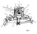
- Fig. 1 shows in a partially sectioned oblique view of an advantageous embodiment of a sprinkler with adjustable irrigation width of a water jet generated by a nozzle assembly DU as a jet image SB.
- the sprinkler has a sprinkler housing GE which can be erected on a floor surface and on which a control cam SK forms a running surface LF which surrounds a rotation axis DA which is vertical in typical setup and a sprinkler head rotatable about the vertical axis of rotation DA relative to the housing GE.
- the tread LF is adjustable in its vertical position relative to the housing GE at a plurality of discrete positions via lever SH.
- a nozzle assembly DU is arranged, which contains at least one nozzle body pivotable about a horizontal nozzle pivot axis VA.
- the nozzle body is pivotable about the nozzle pivot axis VA by means of a lever mechanism of levers TV, TZ and TH, wherein a control lever TH is pivotable about a horizontal lever axis HA and rests with an over the sprinkler RK radially outwardly projecting end on the tread LF.
- water is passed under increased pressure to a drive unit AG arranged in a drive unit via a water inlet WE water, which in in itself known manner causes a rotation of the sprinkler head about the axis of rotation DA.
- the moving along the running surface LF end of the control lever is pivoted in accordance with the non-planar course of the control cam SK and this pivoting is via the lever mechanism TZ, TV transferred to a pivoting of the at least one nozzle body about the pivot axis VA.
- the nozzle body which can be pivoted over the lever mechanism is urged by a spring into a pivoting direction which presses the end of the control lever TH resting against the running surface LF against the running surface LF via the lever mechanism.
- the action of the spring force directly on the pivotable nozzle body of the nozzle assembly DU is particularly advantageous because even with any given game in bearings of the lever mechanism always a defined relationship between the pivot position of the at least one nozzle body to the nozzle pivot axis VA and the height profile of the tread LF of the cam given is.
- Such sprinklers with the rotation angle about a vertical axis of rotation DA depending adjustable irrigation width are also known in various other embodiments.
- the invention is therefore not on the in Fig. 1 illustrated preferred embodiment of a sprinkler limited.
- Essential features of the invention relate to the nozzle arrangement DU, which is preferably held interchangeably in a nozzle carrier DT on the sprinkler head.
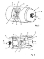
- Fig. 2 shows in isolation a preferred embodiment of a nozzle arrangement which comprises a first nozzle body D1 and a relative to this about the nozzle pivot axis VA pivotable second nozzle body D2 contains.
- a control device for example to the in Fig. 1 Lever shown, is a positive coupling structure HK, which in Fig. 2 star-shaped running around the nozzle pivot axis VA and rotatably connected to a shaft is provided.
- a partial curve K1 is formed, which in the example shown has two opposite, approximately V-shaped edges running down toward one another.
- the sub-curve K1 determines a part of the edge opening bounding a nozzle opening.
- the nozzle opening is in Fig. 2 denoted by OM.
- the edge curve of the nozzle opening OM is bounded at the top by a second nozzle body D2, which in the example sketched has an upper edge K21 and side edges opposite K22.
- Fig. 3 shows the nozzle assembly after Fig. 2 in a partially cutaway view from the back of the Fig. 2 which corresponds to a viewing direction approximately in the direction of the jet ejected through the nozzle opening OM.
- the first nozzle body D1 forms in the in Fig. 2 and Fig. 3 illustrated advantageous embodiment at the same time a substantially cylindrical housing of the nozzle assembly, in which the second nozzle body D2 is pivotally mounted about the nozzle pivot axis VA.
- the star-shaped connection structure HK is coupled to the second nozzle body D2 via a common shaft rotationally fixed with respect to the nozzle pivot axis VA.
- a third nozzle body D3 may be provided, which is preferably arranged non-rotatably in the first nozzle body relative to the first nozzle body.
- the third nozzle body D3 can therefore also be integral with the first nozzle body D1 be formed.
- the embodiment as a separate third nozzle body is based primarily on advantages in terms of manufacturability of the first and third nozzle body as plastic injection molded parts.
- a third sub-curve K3 of the third nozzle body D3 closes the nozzle opening OM downwards. Due to the fixed spatial allocation of the first nozzle body and the third nozzle body, the partial curves K1 and K3 can also be regarded as a partial curve with different curve sections.
- Fig. 3 clearly shows a particularly advantageous embodiment of the pivotable about the nozzle pivot axis VA second nozzle body DA.
- This has upstream of the nozzle opening a guide channel FK, which is bounded by an upper surface and two side surfaces.
- the guide channel FK is open at the bottom.
- the guide channel extends at least approximately linearly with its upper center line, which lies in a vertical plane containing the main beam direction of the emitted beam and the axis of rotation DA.
- the guide channel FK narrows in the direction of flow of the nozzle opening and through this flowing water, the constriction advantageously uniformly continuous.
- the upper surface and the side surfaces of the guide channel FK may be substantially planar in nature and form parts of a truncated pyramid.
- a first section K21 of the second part curve forms a horizontal upper boundary of the nozzle opening and the side edges K22 run obliquely downward from the upper edge K21 while widening the cross section of the guide channel FK.
- Fig. 2 and Fig. 3 selected pivot position of the second nozzle body D2 about the nozzle pivot axis VA portions of the side edges K22 of the second sub-curve of the second nozzle body D2 lateral boundaries of the upper portion of the nozzle opening, which bounded above by the upper edge K21 of the second sub-curve is.
- the continuous course of the boundaries of the guide channel FK favors a largely laminar flow of the water in the region of the guide channel FK to the nozzle opening, so that the ejected in the upper part of the nozzle opening portion of the output from the nozzle assembly water jet emerges in good bundling from the nozzle opening and through the Bundling can achieve a large irrigation range.
- the constricting passage of the guide channel FK also favors a large irrigation width of the bundled portion of the water jet ejected through this part of the nozzle opening by a higher flow velocity associated with the narrowing of the cross section.
- part of the nozzle opening OM takes place in the flow direction in front of the nozzle opening no flow guidance of the water discharged through the nozzle opening, so that the exiting through this part of the nozzle opening water parts are less concentrated and thus advantageously stronger for sprinkling of middle and near Contribute to areas around the sprinkler.
- the lower part of the guide channel, the lower portions of the side edges K22 in the view after Fig. 2 are already covered by the partial curves K1 of the first nozzle body D1, forms a transition region of the flow conditions and the sprinkling distances achieved thereby.
- a middle pivot position of the second nozzle body D2 is selected, against which the upper edge K21 of the second nozzle body D2 is pivotable both upwards and downwards in order to increase or decrease the total cross-sectional area of the nozzle opening.
- the nozzle opening is changed in its upper region, in particular an upper portion of the edge curve of the nozzle opening changed and displaced in height.
- the pivoting of the second nozzle body the inclination angle of the center line of the upper boundary of the guide channel with respect to the axis of rotation DA changed, which significantly determines the beam exit direction of the focused portion of the jet image SB of the discharged water jet.
- a steeper beam exit direction of the bundled portion of the jet pattern SB is advantageously connected to a larger proportion of the second part curve at the edge curve of the nozzle opening, so that at steeper exit angle and a larger bundled beam portion is present, which is for uniform sprinkling at larger throw distances of particular advantage ,
- AR denotes the beam exit direction of the beam portion of the beam pattern SB bundled by the guide channel FK.
- the upper edge K21 of the second part curve of the second nozzle body D2 at the outlet of the guide channel is still spaced from the upper boundary of the first part curve K1 forming recess in the first nozzle body.
- the side edges K22 of the second part curve at the outlet of the guide channel FK lie substantially within the opening formed by the first part curve K1 in the first nozzle body, so that the jet pattern SB determined in its upper region substantially by the second part curve K21, K22 and due to the guide channel FK is designed as a well-bundled beam component.
- the spray pattern is essentially determined by the first nozzle body and its part curve K1 and the substantial absence of flow guidance in front of the nozzle opening and more divergent, whereby the irrigation is reduced and irrigation is also achieved radially closer to the axis of rotation surface areas.
- Fig. 5 shows the nozzle assembly viewed from the ejected water jet, from which the proportions of the first and the second part curve are again illustrated on the edge curve of the nozzle assembly.
- Fig. 6 shows a view obliquely from the front of the nozzle assembly in the maximum irrigation associated position.
- the nozzle opening is designated OH.
- FIGS. 7 to 9 different views of the nozzle assembly are shown in a minimum irrigation width associated pivot position of the second nozzle body, wherein Fig. 7 a partially cut representation of obliquely in front, Fig. 8 a frontal view of the nozzle opening OL and Fig. 9 one too Fig. 6 represent analog oblique view.
- Fig. 7 It can be seen that the direction of the guide channel FK now strongly against the in Fig.
- the second nozzle body and the first nozzle body abut one another in the area of the nozzle opening with surfaces extending in a circular arc around the nozzle pivot axis VA.
- the roller-shaped hollow body forming the first nozzle body is closed at the side by plugs SL, SR, which at the same time determine an axial positioning of the second and third nozzle bodies within the first nozzle body relative to the nozzle pivot axis VA.
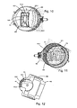
- FIG. 12 an alternative embodiment is outlined, wherein Fig. 10 a view from diagonally forward, Fig. 11 a view from diagonally behind and Fig. 12 represent a view cut in a plane passing through the axis of rotation DA plane view along the nozzle pivot axis VA.
- An annular body RR forms the first nozzle body D1-2 with the first part curve K1 and is open to the rear.
- the third part curve and the continued behind this surface which are formed in the above-described embodiment by the third part body, are formed with a simple configuration of an injection mold on the body RR and the third body omitted as an independent injection molded part.
- the third sub-curve is designated K3-2 and is slightly different with a vertical incision against the horizontal edge profile of the third sub-curve of the previous embodiment.
- the modification has an effect on the jet pattern, in particular with small sprinkling distances.
- the largely identical with the previously described embodiment components the nozzle arrangement are designated by the same reference symbols K1, K21, K22, VA, OM, HK, FK.
- the annular base body RR is connectable with a connection body covering the rear opening of the base body and making the connection to a water guide of the sprinkler head or in the illustration according to FIG Fig. 12 connected.
- the connection may for example be designed as a screw.
- the correct alignment of the nozzle arrangement consisting of the nozzle bodies D1-2 and D2-2 and the connection body KA in a nozzle carrier of the sprinkler head can be ensured, for example, by alignment structures RH cooperating with counterstructures of the nozzle holder on the first nozzle body D1-2.
- the first nozzle body can advantageously be released manually from the connection body.
- the passage of the shaft between the coupling structure HK and the second nozzle body is sealed by a not explicitly drawn shaft seal against the leakage of water.
- the shaft seal is preferably through a U-ring seal is formed, which is arranged on the inside of the plug SR or on the inside of the housing of the annular body RR surrounding the shaft.
Landscapes
- Nozzles (AREA)
Priority Applications (1)
| Application Number | Priority Date | Filing Date | Title |
|---|---|---|---|
| PL10798794T PL2654401T3 (pl) | 2010-12-21 | 2010-12-21 | Zraszacz |
Applications Claiming Priority (1)
| Application Number | Priority Date | Filing Date | Title |
|---|---|---|---|
| PCT/EP2010/070332 WO2012084011A1 (de) | 2010-12-21 | 2010-12-21 | Regner |
Publications (2)
| Publication Number | Publication Date |
|---|---|
| EP2654401A1 EP2654401A1 (de) | 2013-10-30 |
| EP2654401B1 true EP2654401B1 (de) | 2015-02-25 |
Family
ID=44512446
Family Applications (1)
| Application Number | Title | Priority Date | Filing Date |
|---|---|---|---|
| EP10798794.3A Active EP2654401B1 (de) | 2010-12-21 | 2010-12-21 | Regner |
Country Status (3)
| Country | Link |
|---|---|
| EP (1) | EP2654401B1 (pl) |
| PL (1) | PL2654401T3 (pl) |
| WO (1) | WO2012084011A1 (pl) |
Family Cites Families (3)
| Publication number | Priority date | Publication date | Assignee | Title |
|---|---|---|---|---|
| US3878990A (en) * | 1973-01-26 | 1975-04-22 | Hozelock Ltd | Watering devices |
| US4867378A (en) * | 1987-04-13 | 1989-09-19 | Kah Jr Carl L C | Sprinkler device |
| IL108663A (en) * | 1994-02-16 | 2000-08-31 | Mamtirim Dan | Rotary sprinkler |
-
2010
- 2010-12-21 EP EP10798794.3A patent/EP2654401B1/de active Active
- 2010-12-21 WO PCT/EP2010/070332 patent/WO2012084011A1/de not_active Ceased
- 2010-12-21 PL PL10798794T patent/PL2654401T3/pl unknown
Also Published As
| Publication number | Publication date |
|---|---|
| PL2654401T3 (pl) | 2015-08-31 |
| WO2012084011A1 (de) | 2012-06-28 |
| EP2654401A1 (de) | 2013-10-30 |
Similar Documents
| Publication | Publication Date | Title |
|---|---|---|
| DE2552908C2 (pl) | ||
| EP0826426B1 (de) | Regner | |
| EP0641603B1 (de) | Regner, insbesondere zur Vegetations-Bewässerung | |
| EP1851136B1 (de) | Sprühkopf sowie Sprühdose mit einem solchen Sprühkopf | |
| EP0157250B1 (de) | Vorrichtung zum Beizen von Saatgut | |
| EP0970752B1 (de) | Beregnungsvorrichtung | |
| DE10133965A1 (de) | Mähdrescher mit zugehörigem Häcksler und daran anschließenden Wurfgebläsen | |
| DE2100442B2 (de) | Verfahren und Sprühdüse zur Beschichtung der Innenflächen von einseitig geschlossenen zylindrischen Hohlkörpern | |
| DE2803325A1 (de) | Fluessigkeitsspritzkopf und verfahren zum spritzen eines spezifischen musters | |
| DE112012006895B4 (de) | Mischkopf | |
| DE3316296A1 (de) | Reaktionsangetriebener regner | |
| WO2023041655A1 (de) | Lackierpistole und verfahren zum betreiben einer lackierpistole | |
| DE2736314C3 (de) | Düse zum Versprühen eines unter Druck stehenden Mediums | |
| EP3275508A1 (de) | Düse für wasser, insbesondere für einen wasserwerfer | |
| DE2906023C3 (de) | Schlaghebelregner | |
| EP2654401B1 (de) | Regner | |
| EP3088087B1 (de) | Sprühdüse und verfahren zum erzeugen von nicht runden sprühkegeln | |
| DE2815246A1 (de) | Lackspritzpistole | |
| DE202011003941U1 (de) | Farbspritzpistole | |
| DE3588020T2 (de) | Verteiler. | |
| EP1795267B1 (de) | Beregnungsvorrichtung | |
| WO2021151698A1 (de) | Vorrichtung und verfahren zum aufbringen einer reinigungsflüssigkeit auf ein fahrzeugteil | |
| DE102004059105B4 (de) | Schwenkkopf für Gülle-Schwenkverteiler mit Schwenkantrieb durch den Güllestrahl | |
| DE10140457C2 (de) | Mit Schneidmessern besetzte Schnecke eines Futtermischers | |
| DE1534429A1 (de) | Markiervorrichtung zum Herstellen von Verkehrsleitlinien |
Legal Events
| Date | Code | Title | Description |
|---|---|---|---|
| PUAI | Public reference made under article 153(3) epc to a published international application that has entered the european phase |
Free format text: ORIGINAL CODE: 0009012 |
|
| 17P | Request for examination filed |
Effective date: 20130718 |
|
| AK | Designated contracting states |
Kind code of ref document: A1 Designated state(s): AL AT BE BG CH CY CZ DE DK EE ES FI FR GB GR HR HU IE IS IT LI LT LU LV MC MK MT NL NO PL PT RO RS SE SI SK SM TR |
|
| DAX | Request for extension of the european patent (deleted) | ||
| GRAP | Despatch of communication of intention to grant a patent |
Free format text: ORIGINAL CODE: EPIDOSNIGR1 |
|
| INTG | Intention to grant announced |
Effective date: 20140715 |
|
| GRAP | Despatch of communication of intention to grant a patent |
Free format text: ORIGINAL CODE: EPIDOSNIGR1 |
|
| INTG | Intention to grant announced |
Effective date: 20141215 |
|
| GRAS | Grant fee paid |
Free format text: ORIGINAL CODE: EPIDOSNIGR3 |
|
| GRAA | (expected) grant |
Free format text: ORIGINAL CODE: 0009210 |
|
| AK | Designated contracting states |
Kind code of ref document: B1 Designated state(s): AL AT BE BG CH CY CZ DE DK EE ES FI FR GB GR HR HU IE IS IT LI LT LU LV MC MK MT NL NO PL PT RO RS SE SI SK SM TR |
|
| REG | Reference to a national code |
Ref country code: GB Ref legal event code: FG4D Free format text: NOT ENGLISH |
|
| REG | Reference to a national code |
Ref country code: CH Ref legal event code: EP |
|
| REG | Reference to a national code |
Ref country code: IE Ref legal event code: FG4D Free format text: LANGUAGE OF EP DOCUMENT: GERMAN |
|
| REG | Reference to a national code |
Ref country code: DE Ref legal event code: R096 Ref document number: 502010009009 Country of ref document: DE Effective date: 20150409 |
|
| REG | Reference to a national code |
Ref country code: AT Ref legal event code: REF Ref document number: 711107 Country of ref document: AT Kind code of ref document: T Effective date: 20150415 |
|
| REG | Reference to a national code |
Ref country code: LT Ref legal event code: MG4D |
|
| PG25 | Lapsed in a contracting state [announced via postgrant information from national office to epo] |
Ref country code: LT Free format text: LAPSE BECAUSE OF FAILURE TO SUBMIT A TRANSLATION OF THE DESCRIPTION OR TO PAY THE FEE WITHIN THE PRESCRIBED TIME-LIMIT Effective date: 20150225 Ref country code: ES Free format text: LAPSE BECAUSE OF FAILURE TO SUBMIT A TRANSLATION OF THE DESCRIPTION OR TO PAY THE FEE WITHIN THE PRESCRIBED TIME-LIMIT Effective date: 20150225 Ref country code: FI Free format text: LAPSE BECAUSE OF FAILURE TO SUBMIT A TRANSLATION OF THE DESCRIPTION OR TO PAY THE FEE WITHIN THE PRESCRIBED TIME-LIMIT Effective date: 20150225 Ref country code: SE Free format text: LAPSE BECAUSE OF FAILURE TO SUBMIT A TRANSLATION OF THE DESCRIPTION OR TO PAY THE FEE WITHIN THE PRESCRIBED TIME-LIMIT Effective date: 20150225 Ref country code: NO Free format text: LAPSE BECAUSE OF FAILURE TO SUBMIT A TRANSLATION OF THE DESCRIPTION OR TO PAY THE FEE WITHIN THE PRESCRIBED TIME-LIMIT Effective date: 20150525 Ref country code: HR Free format text: LAPSE BECAUSE OF FAILURE TO SUBMIT A TRANSLATION OF THE DESCRIPTION OR TO PAY THE FEE WITHIN THE PRESCRIBED TIME-LIMIT Effective date: 20150225 |
|
| PG25 | Lapsed in a contracting state [announced via postgrant information from national office to epo] |
Ref country code: RS Free format text: LAPSE BECAUSE OF FAILURE TO SUBMIT A TRANSLATION OF THE DESCRIPTION OR TO PAY THE FEE WITHIN THE PRESCRIBED TIME-LIMIT Effective date: 20150225 Ref country code: GR Free format text: LAPSE BECAUSE OF FAILURE TO SUBMIT A TRANSLATION OF THE DESCRIPTION OR TO PAY THE FEE WITHIN THE PRESCRIBED TIME-LIMIT Effective date: 20150526 Ref country code: LV Free format text: LAPSE BECAUSE OF FAILURE TO SUBMIT A TRANSLATION OF THE DESCRIPTION OR TO PAY THE FEE WITHIN THE PRESCRIBED TIME-LIMIT Effective date: 20150225 Ref country code: IS Free format text: LAPSE BECAUSE OF FAILURE TO SUBMIT A TRANSLATION OF THE DESCRIPTION OR TO PAY THE FEE WITHIN THE PRESCRIBED TIME-LIMIT Effective date: 20150625 |
|
| REG | Reference to a national code |
Ref country code: PL Ref legal event code: T3 |
|
| REG | Reference to a national code |
Ref country code: FR Ref legal event code: PLFP Year of fee payment: 6 |
|
| PG25 | Lapsed in a contracting state [announced via postgrant information from national office to epo] |
Ref country code: CZ Free format text: LAPSE BECAUSE OF FAILURE TO SUBMIT A TRANSLATION OF THE DESCRIPTION OR TO PAY THE FEE WITHIN THE PRESCRIBED TIME-LIMIT Effective date: 20150225 Ref country code: RO Free format text: LAPSE BECAUSE OF FAILURE TO SUBMIT A TRANSLATION OF THE DESCRIPTION OR TO PAY THE FEE WITHIN THE PRESCRIBED TIME-LIMIT Effective date: 20150225 Ref country code: EE Free format text: LAPSE BECAUSE OF FAILURE TO SUBMIT A TRANSLATION OF THE DESCRIPTION OR TO PAY THE FEE WITHIN THE PRESCRIBED TIME-LIMIT Effective date: 20150225 Ref country code: SK Free format text: LAPSE BECAUSE OF FAILURE TO SUBMIT A TRANSLATION OF THE DESCRIPTION OR TO PAY THE FEE WITHIN THE PRESCRIBED TIME-LIMIT Effective date: 20150225 Ref country code: DK Free format text: LAPSE BECAUSE OF FAILURE TO SUBMIT A TRANSLATION OF THE DESCRIPTION OR TO PAY THE FEE WITHIN THE PRESCRIBED TIME-LIMIT Effective date: 20150225 |
|
| REG | Reference to a national code |
Ref country code: DE Ref legal event code: R097 Ref document number: 502010009009 Country of ref document: DE |
|
| PLBE | No opposition filed within time limit |
Free format text: ORIGINAL CODE: 0009261 |
|
| STAA | Information on the status of an ep patent application or granted ep patent |
Free format text: STATUS: NO OPPOSITION FILED WITHIN TIME LIMIT |
|
| 26N | No opposition filed |
Effective date: 20151126 |
|
| PG25 | Lapsed in a contracting state [announced via postgrant information from national office to epo] |
Ref country code: SI Free format text: LAPSE BECAUSE OF FAILURE TO SUBMIT A TRANSLATION OF THE DESCRIPTION OR TO PAY THE FEE WITHIN THE PRESCRIBED TIME-LIMIT Effective date: 20150225 |
|
| PG25 | Lapsed in a contracting state [announced via postgrant information from national office to epo] |
Ref country code: BE Free format text: LAPSE BECAUSE OF NON-PAYMENT OF DUE FEES Effective date: 20151231 |
|
| PG25 | Lapsed in a contracting state [announced via postgrant information from national office to epo] |
Ref country code: MC Free format text: LAPSE BECAUSE OF FAILURE TO SUBMIT A TRANSLATION OF THE DESCRIPTION OR TO PAY THE FEE WITHIN THE PRESCRIBED TIME-LIMIT Effective date: 20150225 Ref country code: LU Free format text: LAPSE BECAUSE OF FAILURE TO SUBMIT A TRANSLATION OF THE DESCRIPTION OR TO PAY THE FEE WITHIN THE PRESCRIBED TIME-LIMIT Effective date: 20151221 |
|
| REG | Reference to a national code |
Ref country code: CH Ref legal event code: PL |
|
| REG | Reference to a national code |
Ref country code: IE Ref legal event code: MM4A |
|
| PG25 | Lapsed in a contracting state [announced via postgrant information from national office to epo] |
Ref country code: LI Free format text: LAPSE BECAUSE OF NON-PAYMENT OF DUE FEES Effective date: 20151231 Ref country code: CH Free format text: LAPSE BECAUSE OF NON-PAYMENT OF DUE FEES Effective date: 20151231 Ref country code: IE Free format text: LAPSE BECAUSE OF NON-PAYMENT OF DUE FEES Effective date: 20151221 |
|
| REG | Reference to a national code |
Ref country code: FR Ref legal event code: PLFP Year of fee payment: 7 |
|
| PGFP | Annual fee paid to national office [announced via postgrant information from national office to epo] |
Ref country code: NL Payment date: 20161205 Year of fee payment: 7 Ref country code: GB Payment date: 20161107 Year of fee payment: 7 |
|
| REG | Reference to a national code |
Ref country code: AT Ref legal event code: MM01 Ref document number: 711107 Country of ref document: AT Kind code of ref document: T Effective date: 20151221 |
|
| PG25 | Lapsed in a contracting state [announced via postgrant information from national office to epo] |
Ref country code: SM Free format text: LAPSE BECAUSE OF FAILURE TO SUBMIT A TRANSLATION OF THE DESCRIPTION OR TO PAY THE FEE WITHIN THE PRESCRIBED TIME-LIMIT Effective date: 20150225 Ref country code: BG Free format text: LAPSE BECAUSE OF FAILURE TO SUBMIT A TRANSLATION OF THE DESCRIPTION OR TO PAY THE FEE WITHIN THE PRESCRIBED TIME-LIMIT Effective date: 20150225 Ref country code: HU Free format text: LAPSE BECAUSE OF FAILURE TO SUBMIT A TRANSLATION OF THE DESCRIPTION OR TO PAY THE FEE WITHIN THE PRESCRIBED TIME-LIMIT; INVALID AB INITIO Effective date: 20101221 Ref country code: AT Free format text: LAPSE BECAUSE OF NON-PAYMENT OF DUE FEES Effective date: 20151221 |
|
| PG25 | Lapsed in a contracting state [announced via postgrant information from national office to epo] |
Ref country code: CY Free format text: LAPSE BECAUSE OF FAILURE TO SUBMIT A TRANSLATION OF THE DESCRIPTION OR TO PAY THE FEE WITHIN THE PRESCRIBED TIME-LIMIT Effective date: 20150225 |
|
| PG25 | Lapsed in a contracting state [announced via postgrant information from national office to epo] |
Ref country code: MT Free format text: LAPSE BECAUSE OF FAILURE TO SUBMIT A TRANSLATION OF THE DESCRIPTION OR TO PAY THE FEE WITHIN THE PRESCRIBED TIME-LIMIT Effective date: 20150225 |
|
| REG | Reference to a national code |
Ref country code: FR Ref legal event code: PLFP Year of fee payment: 8 |
|
| PG25 | Lapsed in a contracting state [announced via postgrant information from national office to epo] |
Ref country code: TR Free format text: LAPSE BECAUSE OF FAILURE TO SUBMIT A TRANSLATION OF THE DESCRIPTION OR TO PAY THE FEE WITHIN THE PRESCRIBED TIME-LIMIT Effective date: 20150225 Ref country code: PT Free format text: LAPSE BECAUSE OF FAILURE TO SUBMIT A TRANSLATION OF THE DESCRIPTION OR TO PAY THE FEE WITHIN THE PRESCRIBED TIME-LIMIT Effective date: 20150225 Ref country code: MK Free format text: LAPSE BECAUSE OF FAILURE TO SUBMIT A TRANSLATION OF THE DESCRIPTION OR TO PAY THE FEE WITHIN THE PRESCRIBED TIME-LIMIT Effective date: 20150225 |
|
| REG | Reference to a national code |
Ref country code: NL Ref legal event code: MM Effective date: 20180101 |
|
| GBPC | Gb: european patent ceased through non-payment of renewal fee |
Effective date: 20171221 |
|
| PG25 | Lapsed in a contracting state [announced via postgrant information from national office to epo] |
Ref country code: NL Free format text: LAPSE BECAUSE OF NON-PAYMENT OF DUE FEES Effective date: 20180101 |
|
| PG25 | Lapsed in a contracting state [announced via postgrant information from national office to epo] |
Ref country code: AL Free format text: LAPSE BECAUSE OF FAILURE TO SUBMIT A TRANSLATION OF THE DESCRIPTION OR TO PAY THE FEE WITHIN THE PRESCRIBED TIME-LIMIT Effective date: 20150225 |
|
| PG25 | Lapsed in a contracting state [announced via postgrant information from national office to epo] |
Ref country code: GB Free format text: LAPSE BECAUSE OF NON-PAYMENT OF DUE FEES Effective date: 20171221 |
|
| PGFP | Annual fee paid to national office [announced via postgrant information from national office to epo] |
Ref country code: PT Payment date: 20181121 Year of fee payment: 5 |
|
| PGFP | Annual fee paid to national office [announced via postgrant information from national office to epo] |
Ref country code: FR Payment date: 20181120 Year of fee payment: 9 Ref country code: IT Payment date: 20181018 Year of fee payment: 9 |
|
| PG25 | Lapsed in a contracting state [announced via postgrant information from national office to epo] |
Ref country code: FR Free format text: LAPSE BECAUSE OF NON-PAYMENT OF DUE FEES Effective date: 20191231 Ref country code: IT Free format text: LAPSE BECAUSE OF NON-PAYMENT OF DUE FEES Effective date: 20191221 |
|
| PG25 | Lapsed in a contracting state [announced via postgrant information from national office to epo] |
Ref country code: PL Free format text: LAPSE BECAUSE OF NON-PAYMENT OF DUE FEES Effective date: 20191221 |
|
| P01 | Opt-out of the competence of the unified patent court (upc) registered |
Effective date: 20230419 |
|
| PGFP | Annual fee paid to national office [announced via postgrant information from national office to epo] |
Ref country code: DE Payment date: 20241111 Year of fee payment: 15 |