EP2654191B1 - Reduzierung von Wärmespannungen in Flugzeugmotorsteuerungen - Google Patents
Reduzierung von Wärmespannungen in Flugzeugmotorsteuerungen Download PDFInfo
- Publication number
- EP2654191B1 EP2654191B1 EP13164707.5A EP13164707A EP2654191B1 EP 2654191 B1 EP2654191 B1 EP 2654191B1 EP 13164707 A EP13164707 A EP 13164707A EP 2654191 B1 EP2654191 B1 EP 2654191B1
- Authority
- EP
- European Patent Office
- Prior art keywords
- level
- pwm mode
- level pwm
- motor controller
- interval
- Prior art date
- Legal status (The legal status is an assumption and is not a legal conclusion. Google has not performed a legal analysis and makes no representation as to the accuracy of the status listed.)
- Active
Links
Images






Classifications
-
- F—MECHANICAL ENGINEERING; LIGHTING; HEATING; WEAPONS; BLASTING
- F02—COMBUSTION ENGINES; HOT-GAS OR COMBUSTION-PRODUCT ENGINE PLANTS
- F02C—GAS-TURBINE PLANTS; AIR INTAKES FOR JET-PROPULSION PLANTS; CONTROLLING FUEL SUPPLY IN AIR-BREATHING JET-PROPULSION PLANTS
- F02C7/00—Features, components parts, details or accessories, not provided for in, or of interest apart form groups F02C1/00 - F02C6/00; Air intakes for jet-propulsion plants
- F02C7/26—Starting; Ignition
-
- H—ELECTRICITY
- H02—GENERATION; CONVERSION OR DISTRIBUTION OF ELECTRIC POWER
- H02M—APPARATUS FOR CONVERSION BETWEEN AC AND AC, BETWEEN AC AND DC, OR BETWEEN DC AND DC, AND FOR USE WITH MAINS OR SIMILAR POWER SUPPLY SYSTEMS; CONVERSION OF DC OR AC INPUT POWER INTO SURGE OUTPUT POWER; CONTROL OR REGULATION THEREOF
- H02M7/00—Conversion of AC power input into DC power output; Conversion of DC power input into AC power output
- H02M7/42—Conversion of DC power input into AC power output without possibility of reversal
- H02M7/44—Conversion of DC power input into AC power output without possibility of reversal by static converters
- H02M7/48—Conversion of DC power input into AC power output without possibility of reversal by static converters using discharge tubes with control electrode or semiconductor devices with control electrode
- H02M7/483—Converters with outputs that each can have more than two voltages levels
- H02M7/487—Neutral point clamped inverters
-
- H—ELECTRICITY
- H02—GENERATION; CONVERSION OR DISTRIBUTION OF ELECTRIC POWER
- H02P—CONTROL OR REGULATION OF ELECTRIC MOTORS, ELECTRIC GENERATORS OR DYNAMO-ELECTRIC CONVERTERS; CONTROLLING TRANSFORMERS, REACTORS OR CHOKE COILS
- H02P9/00—Arrangements for controlling electric generators for the purpose of obtaining a desired output
- H02P9/08—Control of generator circuit during starting or stopping of driving means, e.g. for initiating excitation
Definitions
- the present invention relates to aircraft electric start motors, and more specifically, to motor controllers for managing thermal stress associated with electrical start of aircraft engines.
- the engines in an aircraft are typically started by non-electrical methods, for example, a start turbine driven by compressed air.
- An increased number of aircrafts in recent years have begun to use electric generators to start the engine by operating the generator in motoring mode, powered by a motor controller.
- the motor controllers on aircraft are typically designed for other continuous duty applications, such as, cabin air compressor, air recirculation fans, and fuel pumps.
- cabin air compressor typically one or two of the available motor controllers are called upon from their normal duty to start the engine, and then returned to their normal duty.
- the motor controller semiconductor power switches e.g., an insulated gate bipolar transistor (IGBT) switch
- IGBT insulated gate bipolar transistor
- US 2010/289328 A1 discloses an aircraft motor controller configured to control an electric power generator coupled to an aircraft engine.
- D4 relates to a three-level NPC inverter acting as a motor controller for an electric vehicle, and describes control means for controlling said inverter to be in a two-level mode of operation when the line-to-line voltage is lower than a predetermined reference voltage, and to be in a three-level mode of operation when the line-to-line voltage detected is higher than the predetermined reference voltage.
- a thermal stress reduction method for an aircraft motor controller having a three-level inverter switch array, and configured to control an electric power starter/generator coupled to an aircraft engine includes ramping the electric power starter/generator to start the aircraft engine, for a time period associated with the aircraft engine start sequence toggling the three-level inverter switch array to a three-level pulse width modulation mode, determining if a first time interval in the three-level pulse width modulation mode exceeded a predetermined three-level pulse width modulation mode interval.
- the method further includes toggling the three-level inverter switch array to a two-level pulse width modulation mode, determining if a second time interval in the two-level pulse width modulation mode exceeded a predetermined two-level pulse width modulation mode interval and in response to the second time interval exceeding the two-level pulse width modulation mode interval, toggling the three-level inverter switch array to the three-level pulse width modulation mode.
- a ratio of three-level PWM mode interval to the two-level PWM mode internal is inversely proportional to a ratio of a three-level PWM mode thermal loss to a two-level PWM mode thermal loss; and/or wherein a carrier frequency in the two-level PWM mode is greater than a carrier frequency in the three-level PWM mode.
- Additional exemplary embodiments include an engine start system with an electric power starter/generator, an aircraft engine coupled to the electric power starter/generator, an aircraft motor controller coupled to the electric power generator.
- the system further includes a thermal stress reduction process residing on the motor controller and configured to ramp the electric power starter/generator to start the aircraft engine, for a time period associated with the aircraft engine start sequence toggle the three-level inverter switch array to a three-level pulse width modulation mode, determine if a first time interval in the three-level pulse width modulation mode exceeded a predetermined three-level pulse width modulation mode interval.
- the process is further configured to, in response to the first time interval exceeding the three-level pulse width modulation mode interval, toggle the three-level inverter switch array to a two-level pulse width modulation mode, determine if a second time interval in the two-level pulse width modulation mode exceeded a predetermined two-level pulse width modulation mode interval, and in response to the second time interval exceeding the two-level pulse width modulation mode interval, toggle the three-level inverter switch array to the three-level pulse width modulation mode.
- a ratio of three-level PWM mode interval to the two-level PWM mode internal is inversely proportional to a ratio of a three-level PWM mode thermal loss to a two-level PWM mode thermal loss; and/or wherein a carrier frequency in the two-level PWM mode is greater than a carrier frequency in the three-level PWM mode.
- Additional exemplary embodiments may include, during an aircraft engine start sequence, a thermal stress reduction method for an aircraft motor controller having a three-level inverter switch array, and configured to control an electric power starter/generator coupled to an aircraft engine.
- the method may include ramping the electric power generator to start the aircraft engine, and for a time period associated with the aircraft engine start sequence, applying a current profile to the current from the electric power generator to the aircraft engine.
- the current profile may control the current to reduce the thermal dissipation in the three-level inverter switch.
- Additional exemplary embodiments may include an engine start system with an electric power starter/generator having a three-level inverter, an aircraft engine coupled to the electric power generator, an aircraft motor controller coupled to the electric power generator, a thermal stress reduction process residing on the motor controller and configured to ramp the electric power generator to start the aircraft engine and for a time period associated with the aircraft engine start sequence, apply a current profile to the current from the electric power generator to the aircraft engine, the current profile controlling the current to reduce the thermal dissipation in the three-level inverter switch.
- Additional exemplary embodiments may include, during an aircraft engine start sequence, a thermal stress reduction method for an aircraft motor controller having a three-level inverter switch array, and configured to control an electric power generator coupled to an aircraft engine, the method including ramping the electric power generator to start the aircraft engine and for a time period associated with the aircraft engine start sequence, ramping an output frequency of the motor controller from an initial frequency, and controlling the output frequency to reduce the thermal dissipation in the three-level inverter switch.
- FIG. 1 may depict an engine start system, including an electric power starter/generator having a three-level inverter, an aircraft engine coupled to the electric power generator, an aircraft motor controller coupled to the electric power generator, a thermal stress reduction process residing on the motor controller and configured to ramp the electric power generator to start the aircraft engine and for a time period associated with the aircraft engine start sequence, ramping an output frequency of the motor controller from an initial frequency, controlling the output frequency to reduce the thermal dissipation in the three-level inverter switch.
- an engine start system including an electric power starter/generator having a three-level inverter, an aircraft engine coupled to the electric power generator, an aircraft motor controller coupled to the electric power generator, a thermal stress reduction process residing on the motor controller and configured to ramp the electric power generator to start the aircraft engine and for a time period associated with the aircraft engine start sequence, ramping an output frequency of the motor controller from an initial frequency, controlling the output frequency to reduce the thermal dissipation in the three-level inverter switch.
- FIG. 1 illustrates a schematic diagram of an engine start circuit 100 in which the exemplary methods and systems described herein are implemented.
- the starter/generator spins up with or without the engine engaged.
- the generators are implemented for various tasks on the aircraft, and can also be implemented to start the engines.
- the curve 101 represents the applied power and the curve 102 represents the resultant speed.
- the generator applies a constant torque for a speed ramp.
- the generator provides constant power with a constant speed.
- the generator ramps down the applied power and the speed remains constant.
- frequency control is typically implemented, synchronizing the starter/generator frequency to bus frequency and bypassing control from the motor controller.
- the speed stays constant and the engines are engaged and begin acceleration.
- the engines ignite and become fully functional.
- FIG 2 schematically illustrates an engine start circuit 200 in which exemplary embodiments may be implemented.
- a motor controller 210 is fed from a variable frequency/constant frequency (VF / CF) bus 220 through a contactor/breaker 230.
- the output of motor controller 210 is connected to starter/generator 240 through a contactor/breaker 250, which is in parallel with a contactor/breaker 260.
- the motor controller 210 is coupled to the generator 240 via a generator control unit (GCU) 270.
- the starter/generator 240 is coupled to the aircraft engine 280 via suitable transmission and coupling 290. After the generator 240 spins up to near synchronous speed and is synchronized with the bus, the contactor/breaker 250 opens and contactor/breaker 260 closes.
- GCU generator control unit
- the electric power generators are also driven by the aircraft engines to generate electricity for power distribution within the aircraft.
- the engines are often started by using these generators in motoring mode, thus eliminating need for air-driven turbine starters.
- the spin up of the generator lasts typically from a few seconds to tens of seconds, depending on the engine size and if the engine is engaged when spinning the generator. Consequently there is no dedicated engine start motor controller. Instead, a motor controller installed for driving other normal duty aircraft loads may be called upon to perform this short engine start duty.
- FIG. 3 illustrates a three-level inverter IGBT switch array 300 in which exemplary embodiments for toggling between a two-level pulse width modulation (PWM mode and a three-level PWM mode may be implemented. It can be appreciated that other power switches can be implemented in other exemplary embodiments.
- the array 300 includes three legs 310, 320, 330, each leg 310, 320, 330 including one or more IGBT switches.
- the IGBT switch is implemented with the motor controllers (e.g., the motor controller 210 in FIG. 2 ) of aircraft.
- a three-level inverter motor drive PWM control method is implemented to spread the power semiconductor (e.g. IGBT) thermal stress more evenly during an electrical start of the aircraft engines.
- one of the motor controller power semiconductor switch (e.g., IGBT) junction could be subject to a very high thermal stress for a short duration, typically under a second), while the other semiconductor switches are less stressed or even not stressed at all during this same period.
- the motor controller IGBT switches would have to be sized based on this brief undistributed thermal stress resulting in undesirable weight increase.
- the engine start duty stresses the motor controller differently as compared to a continuous motoring load. Significant among the differences is the very high thermal and power stresses to the IGBT switch within the first quarter electrical cycle (i.e., the first time period 110 of FIG. 1 ).
- FIG. 3 illustrates, for example, that during peak current conditions in the motor controller, two switches 311 in the first leg 310 experience the highest thermal stress. During half peak current conditions, two of the switches 321, 331 in the second and third legs 320, 330, respectively, experience the highest thermal stress.
- the exemplary methods described herein spread the thermal stresses more evenly during engine start-up.
- the first quarter e.g., the first time period 110 of FIG. 1
- the IGBT switch junction temperature rise can double or even triple in comparison to normal steady state (higher frequency) operation.
- Increasing the IGBT switch size and weight, and hence the overall motor controller package size and weight, for the sake of this short duty-cycle (one minute) engine start can be addressed with the methods described herein without changing the motor controller package size and weight.
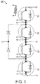
- FIG. 4 illustrates an interconnection of four semiconductor switches S1, S2, S3, S4 of one leg 400 in a three-level phase motor controller.
- the leg 400 can be any of the legs 310, 320, 330 of FIG. 3 .
- switches S1, S4 are referred to as “outer” switches
- switches S2, S3 are referred to as “inner” switches.
- the starter/generator e.g., the generator 240 in FIG. 2
- the engine e.g., the engine 280 in FIG. 2
- the motor controller output is a three phase ac voltage with a frequency ramp up from 0Hz (or near 0Hz) to 400Hz. Because of the slow frequency ramp, one of the inverter switches could experience a switching loss of nearly 3.14 times of that during normal high frequency steady-state operation, in a two-level inverter or three-level inverter.
- the IGBT switch thermal time constant is typically less than 100ms. It is normally the first output cycle sinusoidal peak that thermally stresses the IGBT switch the most during this engine start-up. During this first half of the output frequency cycle, one of the outer switches is continually switching and the adjacent inner switch is in a steady ON state.
- the outer and inner IGBT switches in a three-level inverter are switched alternately so the thermal stress to a particular IGBT is reduced significantly resulting in a reasonable rating for the switches during electrical engine start.
- the PWM method toggles between a three-level PWM (when the outer switches perform the PWM switching) mode and a two-level PWM (when the inner switches perform the PWM switching) mode, thus more evenly spreading the number of switching instants between the outer and inner switches.
- the method reduces the outer switches thermal stress by shifting part of the thermal loss to the inner switches
- FIG. 5 illustrates the switch array 300 of FIG. 3 in a three-level PWM mode.
- a pulsing scheme chart 500 for a three-level PWM mode is also illustrated.
- FIG. 5 illustrates peak current switching ON in switch S1, peak current ON in switch S2, in leg 310, and half peak current ON in switch S3 and half peak current switching ON in switch S4 in the legs 320, 330,
- S1 in Phase A would be stressed the most.
- the outer switch S1 junction temperature could reach 168C during the first cycle of engine start and the inner switch junction temperature would only reach 98C, a difference of 70C.
- FIG. 6 illustrates the switch array 300 of FIG. 3 in a two-level PWM mode.
- a pulsing scheme chart 600 for a two-level PWM mode is also illustrated.
- FIG. 6 illustrates peak current ON in switch S1, peak current switching ON in switch S2, in leg 310, and half peak current switching ON in switch S3 and half peak current ON in switch S4 in the legs 320, 330. If the outer switches are forced to stay in the ON state, and the inner switches are utilized for PWM switching, as illustrated in FIG. 6 , the losses on outer switches would be significantly reduced. However, the inner switches are dissipating higher losses in this mode of operation.
- FIG. 7 illustrates an example of a plot 700 of switch gate control signals for one phase that illustrate switching between the two-level PWM mode and the three-level PWM mode in accordance with exemplary embodiments. The switching losses for the three-level and the two-level PWM modes are different.
- a ratio is selected for the time intervals for the three-level PWM mode and the two-level PWM mode to be inversely proportional to the ratio of the three-level PWM mode loss in the switch versus the two-level PWM mode loss in the switch.
- higher switching frequencies or carrier frequencies can be used in the two-level PWM mode to reduce common mode voltage output if a common mode filter is used, thereby decreasing the weight and size of the output common-mode filters.
- the two-level PWM mode alternating time period is less than the semiconductor thermal time constant of the switches.
- FIG. 8 illustrates a flowchart for a method 800 of toggling between a two-level PWM mode and a three-level PWM mode in accordance with exemplary embodiments.
- the motor controller e.g., the motor controller 210 of FIG. 2
- the motor controller determines whether the elapsed time in the three-level PWM mode has surpassed a pre-determined three-level PWM mode interval. During this time, an increased amount of thermal (power) dissipation occurs on switches S1, S4 as described herein.
- the predetermined three-level PWM mode interval is selected to switch from the three-level PWM mode before the switches S1, S4 overheat. If the time interval in the three-level PWM mode has not surpassed the pre-determined three-level PWM mode interval at block 820, then the motor controller stays in the three-level PWM mode at block 810. If the time interval in the three-level PWM mode has surpassed the pre-determined three-level PWM mode interval at block 820, then the motor controller enters into a two-level PWM mode at block 830, in which a timer is set for the two-level PWM mode. At block 840, the motor controller determines whether the elapsed time in the two-level PWM mode has surpassed a pre-determined two-level PWM mode interval.
- the predetermined two-level PWM mode interval is selected to switch from the three-level PWM mode before the switches S2, S3 overheat. If the time interval in the two-level PWM mode has not surpassed the pre-determined two-level PWM mode interval at block 840, then the motor controller stays in the two-level PWM mode at block 830. If the time interval in the two-level PWM mode has surpassed the pre-determined two-level PWM mode interval at block 840, then the motor controller enters back into a three-level PWM mode at block 830, in which a timer is set for the three-level PWM mode. It can be appreciated that this method 800 repeats thereby toggling between the two-level PWM mode and the three-level PWM mode during the engine start-up as described herein.
- a current profile method that includes a motor controller current profile that reduces IGBT thermal stress during an electrical start of the main engine can be implemented.
- the motor controller e.g., the motor controller 210 of FIG. 2
- the power semiconductor switch e.g., IGBT
- the motor controller IGBT switch would have to be sized based on this brief thermal stress resulting in undesirable weight increase.
- the IGBT switch thermal stress is reduced significantly so that IGBT switch size increase would not be necessary for engine start duty, hence reducing the aircraft weight.
- the motor controller designed for a certain continuous motor load can be used to spin the generator machine up to 400Hz to start the engine.
- the generator is of the wound-field synchronous type.
- the engine may or may not be connected to the generator when spinning the generator.
- the motor controller output is a three phase AC voltage with a frequency ramp up from zero or close to zero frequency to 400Hz. Because of the slow frequency ramp, one of the IGBT switch could experience a switching loss of nearly 3.14 times of that during a high frequency steady operation.
- the IGBT thermal time constant is less than 100ms.
- the first output cycle sinusoidal peak thermally stresses the IGBT switch the most compared to subsequent peaks. Therefore, if the current is reduced during the first quarter cycle, the IGBT thermal stress would be reduced significantly. Because the current is only reduced for a very short duration the overall generator acceleration time is not noticeably affected.
- FIG. 9 illustrates a three-level inverter IGBT switch array 900 in which exemplary embodiments for applying a current control method can be implemented.
- the array 900 includes three legs 910, 920, 930, each leg 910, 920, 930 including one or more IGBT switches.
- the IGBT switch is implemented with the motor controllers (e.g., the motor controller 210 in FIG. 2 ) of aircraft.
- a current control method is implemented to spread the power semiconductor (e.g. IGBT) thermal stress more evenly during an electrical start of the aircraft engines.
- the engine start duty stresses the motor controller differently as compared to a continuous motoring load.
- FIG. 9 illustrates, for example, that during peak current conditions in the motor controller, one switch 911 in the first leg 910 experiences the highest thermal stress.
- the exemplary methods described herein spread the thermal stresses more evenly during engine start-up.
- the IGBT switch junction temperature rise can double or even triple in comparison to normal steady state (higher frequency) operation.
- Increasing the IGBT switch size and weight, and hence the overall motor controller package size and weight, for the sake of this short duty-cycle (one minute) engine start can be addressed with the methods described herein without changing the motor controller package size and weight.
- the IGBT switch peak junction temperature is significantly reduced by controlling the motor current magnitude profile.
- the current magnitude starts at 0.5 per unit (pu) and increases to 1.0 pu in 0.6 seconds
- the peak IGBT switch junction temperature could be reduced by nearly 30°C.
- rate of current increase per unit time temperature reduction in the IGBT is attained.
- the IGBT switch junction temperature reaches the peak at around the first current peak and decays nearly exponentially. Therefore if the current profile is increased following a near exponential curve, a low flat peak temperature of the IGBT switch is achieved while maximizing the available torque for accelerating the generator. Another 12°C of IGBT switch temperature reduction is achieved by implementing an exponential current profile.
- a frequency ramp is from a non-zero frequency, further temperature reduction of the IGBT switch can be achieved.
- motor controller output current could ramp from a higher initial value to boost acceleration torque.
- a dwell time at the initial non-zero frequency can also be introduced.
- the non-zero frequency allows time for the rotor to catch up with the stator field.
- Synchronous and induction torques enable rotor pole alignment.
- a motor controller designed for other motoring load applications can be used for engine start without increasing the IGBT switch size.
- FIG. 10 illustrates a flowchart for a method 1000 of applying a current profile to a motor controller in accordance with exemplary embodiments.
- an appropriate current profile as described herein is programmed into the motor controller.
- a frequency ramp method reduces IGBT thermal stress during an electrical start of the main engine can be implemented.
- the motor controller e.g., the motor controller 210 of FIG. 2
- the power semiconductor switch e.g., IGBT
- the motor controller IGBT switch would have to be sized based on this brief thermal stress resulting in undesirable weight increase.
- the frequency ramp profile described herein the IGBT switch thermal stress is reduced significantly so that IGBT switch size increase would not be necessary for engine start duty, hence reducing the aircraft weight.
- the motor controller designed for a certain continuous motor load can be used to spin the generator up to 400Hz to start the engine.
- the engine may or may not be connected to the generator when spinning the generator.
- the motor controller output is a three phase AC voltage with a frequency ramps up from zero or close to zero frequency to 400Hz. Because of the slow frequency ramp, one of the IGBT could experience a switching loss of nearly 3.14 times of that during a high frequency steady operation.
- the IGBT thermal time constant is typically less than 100ms. Typically, the first sinusoidal peak stresses the IGBT the most as compared to other peaks.
- a frequency ramp from a non-zero frequency reduces peak IGBT switch thermal stresses not only if rotor position is known and fed back to the motor controller, but also if the rotor position is unknown and an open-loop generator start algorithm is utilized.
- IGBT switch thermal stresses are reduced significantly so that the IGBT switch size increase would not be necessary for engine start duty, hence reducing the aircraft weight.
- the exemplary frequency ramp methods can be implemented in the three-level inverter IGBT switch array 900.
- the frequency ramp method is implemented to spread the power semiconductor (e.g. IGBT) thermal stress more evenly during an electrical start of the aircraft engines.
- the IGBT peak junction temperature is relieved by ramping up the motor controller output frequency from a non-zero frequency.
- a non-zero frequency e.g., 4 Hz
- localized heating is reduced at one particular IGBT by shifting the heat between different IGBT's in time. As such, the IGBT's are heated more evenly.
- the frequency ramp method can be implemented. At the beginning of the engine start, when the rotor position is unknown, starting from a non-zero frequency generates an induction torque through damper windings. This induction torque is always in forward direction and aids the initial pole alignment and acceleration.
- a 1% starting frequency i.e., about 4Hz gives 1% slip
- an 8% starting frequency would give 2% slip, for example.
- starting from 4 Hz would result in a 10°C IGBT junction temperature reduction
- from 8 Hz would result in a 20°C temperature reduction.
- a dwell time at the initial non-zero frequency can also be introduced to give time for the rotor to catch up with the stator field, and pull into synchronization by synchronous torque.
- a motor controller designed for other motoring load applications can be used for engine start without increasing the IGBT size.
- FIG. 11 illustrates a flowchart for a method 1100 of applying a frequency ramp to a motor controller in accordance with exemplary embodiments.
- an appropriate frequency ramp as described herein is programmed into the motor controller.
- the motor controllers described herein can be any suitable microcontroller or microprocessor for executing the instructions (e.g., on/off commands) described herein.
- the suitable microcontroller or microprocessor can be any custom made or commercially available processor, a central processing unit (CPU), an auxiliary processor among several processors, a semiconductor based microprocessor (in the form of a microchip or chip set), a macroprocessor, or generally any device for executing software instructions.
- aspects of the present invention may be embodied as a system, method or computer program product. Accordingly, aspects of the present invention may take the form of an entirely hardware embodiment, an entirely software embodiment (including firmware, resident software, micro-code, etc.) or an embodiment combining software and hardware aspects that may all generally be referred to herein as a "circuit,” “module” or “system.” Furthermore, aspects of the present invention may take the form of a computer program product embodied in one or more computer readable medium(s) having computer readable program code embodied thereon.
- each block in the flowchart or block diagrams may represent a module, segment, or portion of code, which comprises one or more executable instructions for implementing the specified logical function(s).
- the functions noted in the block may occur out of the order noted in the figures. For example, two blocks shown in succession may, in fact, be executed substantially concurrently, or the blocks may sometimes be executed in the reverse order, depending upon the functionality involved.
- the methods described herein can implemented with any or a combination of the following technologies, which are each well known in the art: a discrete logic circuit(s) having logic gates for implementing logic functions upon data signals, an application specific integrated circuit (ASIC) having appropriate combinational logic gates, a programmable gate array(s) (PGA), a field programmable gate array (FPGA), etc.
- ASIC application specific integrated circuit
- PGA programmable gate array
- FPGA field programmable gate array
Landscapes
- Engineering & Computer Science (AREA)
- Power Engineering (AREA)
- Chemical & Material Sciences (AREA)
- Combustion & Propulsion (AREA)
- Mechanical Engineering (AREA)
- General Engineering & Computer Science (AREA)
- Inverter Devices (AREA)
- Control Of Eletrric Generators (AREA)
- Electric Propulsion And Braking For Vehicles (AREA)
Claims (14)
- Verfahren zur Reduzierung von Wärmespannungen für eine Flugzeugmotorsteuerung (210), die dazu konfiguriert ist, einen elektrischen Leistungsgenerator (240), der an ein Flugzeugtriebwerk (280) gekoppelt ist, zu steuern, wobei das Verfahren dadurch gekennzeichnet ist, dass die Motorsteuerung (34) ein Dreipunktwechselrichterschalterfeld (300) aufweist; und gekennzeichnet durch
Hochfahren des elektrischen Leistungsgenerators (240), um das Flugzeugtriebwerk (280) zu starten;
während eines Zeitraums, der mit einer Flugzeugtriebwerksstartsequenz assoziiert ist:Umschalten des Dreipunktwechselrichterschalterfelds (300) auf einen Dreipunktpulsbreitenmodulationsmodus (Dreipunkt-PWM-Modus);Bestimmen, ob ein erstes Zeitintervall in dem Dreipunkt-PWM-Modus ein vorbestimmtes Dreipunkt-PWM-Modus-Intervall überschreitet;Umschalten des Dreipunktwechselrichterschalterfelds (300) auf einen Zweipunkt-PWM-Modus als Reaktion darauf, dass das erste Zeitintervall das Dreipunkt-PWM-Modus-Intervall überschreitet;Bestimmen, ob ein zweites Zeitintervall in dem Zweipunkt-PWM-Modus ein vorbestimmtes Zweipunkt-PWM-Modus-Intervall überschreitet; undUmschalten des Dreipunktwechselrichterschalterfelds (300) auf den Dreipunkt-PWM-Modus als Reaktion darauf, dass das zweite Zeitintervall das Zweipunkt-PWM-Modus-Intervall überschreitet, und wobei ein Verhältnis des Dreipunkt-PWM-Modus-Intervalls zu dem Zweipunkt-PWM-Modus-Intervall innen umgekehrt proportional zu einem Verhältnis eines Dreipunkt-PWM-Modus-Wärmeverlusts zu einem Zweipunkt-PWM-Modus-Wärmeverlust ist; und/oder wobei eine Trägerfrequenz in dem Zweipunkt-PWM-Modus größer ist als eine Trägerfrequenz in dem Dreipunkt-PWM-Modus. - Triebwerksstartsystem, das Folgendes umfasst:einen elektrischen Leistungsgenerator (240);ein Flugzeugtriebwerk (280), das an den elektrischen Leistungsgenerator (240) gekoppelt ist;eine Flugzeugmotorsteuerung (210), die an den elektrischen Leistungsgenerator (240) gekoppelt ist, und dadurch gekennzeichnet ist, dass der elektrische Leistungsgenerator (240) ein Dreipunktwechselrichterschalterfeld (300) aufweist, wobei die Flugzeugmotorsteuerung (210) zu Folgendem konfiguriert ist:Hochfahren des elektrischen Leistungsgenerators, um das Flugzeugtriebwerk (280) zu starten;während einer Zeitdauer, die mit der Flugzeugtriebwerkstartsequenz assoziiert ist:Umschalten des Dreipunktwechselrichterschalterfelds (300) auf einen Dreipunktpulsbreitenmodulationsmodus (Dreipunkt-PWM-Modus);Bestimmen, ob ein erstes Zeitintervall in dem Dreipunkt-PWM-Modus ein vorbestimmtes Dreipunkt-PWM-Modus-Intervall überschritten hat;Umschalten des Dreipunktwechselrichterschalterfelds (300) auf einen Zweipunkt-PWM-Modus als Reaktion darauf, dass das erste Zeitintervall das Dreipunkt-PWM-Modus-Intervall überschreitet;Bestimmen, ob ein zweites Zeitintervall in dem Zweipunkt-PWM-Modus ein vorbestimmtes Zweipunkt-PWM-Modus-Intervall überschritten hat; undUmschalten des Dreipunktwechselrichterschalterfelds (300) auf den Dreipunkt-PWM-Modus als Reaktion darauf, dass das zweite Zeitintervall das Zweipunkt-PWM-Modus-Intervall überschreitet, und wobei ein Verhältnis des Dreipunkt-PWM-Modus-Intervalls zu dem Zweipunkt-PWM-Modus-Intervall innen umgekehrt proportional zu einem Verhältnis eines Dreipunkt-PWM-Modus-Wärmeverlusts zu einem Zweipunkt-PWM-Modus-Wärmeverlust ist; und/oder wobei eine Trägerfrequenz in dem Zweipunkt-PWM-Modus größer ist als eine Trägerfrequenz in dem Dreipunkt-PWM-Modus.
- Verfahren nach Anspruch 1 oder System nach Anspruch 2, wobei das Dreipunktwechselrichterschalterfeld (300) einen ersten Schalter, einen zweiten Schalter, einen dritten Schalter und einen vierten Schalter beinhaltet, wobei der erste Schalter, der zweite Schalter, der dritte Schalter und der vierte Schalter in einer seriellen Anordnung konfiguriert sind.
- Verfahren oder System nach Anspruch 3, wobei der erste und der vierte Schalter während des Dreipunkt-PWM-Modus eine größere Menge an Wärmeenergie relativ zu dem zweiten und dem dritten Schalter ableiten.
- Verfahren oder System nach Anspruch 4, wobei der zweite und der dritte Schalter während des Zweipunkt-PWM-Modus eine größere Menge an Wärmeenergie relativ zu dem ersten und dem vierten Schalter ableiten.
- Verfahren zur Reduzierung von Wärmespannungen für eine Flugzeugmotorsteuerung (210) nach Anspruch 1, wobei das Verfahren ferner Folgendes umfasst:
während einer Zeitdauer, die mit einer Flugzeugtriebwerkstartsequenz assoziiert ist, Aufbringen eines Stromprofils auf den Strom von dem elektrischen Leistungsgenerator (240) an das Flugzeugtriebwerk (280), wobei das Stromprofil den Strom steuert, um die Wärmeableitung in dem Dreipunktwechselrichterschalter zu reduzieren. - Triebwerkstartsystem nach Anspruch 2, das ferner zu Folgendem konfiguriert ist:Hochfahren des elektrischen Leistungsgenerators, um das Flugzeugtriebwerk zu starten; undwährend einer Zeitdauer, die mit der Flugzeugtriebwerkstartsequenz assoziiert ist, Aufbringen eines Stromprofils auf den Strom von dem elektrischen Leistungsgenerator (240) an das Flugzeugtriebwerk (280), wobei das Stromprofil den Strom steuert, um die Wärmeableitung in dem Dreipunktwechselrichterschalter zu reduzieren.
- Verfahren nach Anspruch 6 oder System nach Anspruch 7, wobei das Stromprofil eingestellt wird, um eine Stromgröße pro Zeiteinheit zu steuern.
- Verfahren nach Anspruch 6 oder System nach Anspruch 7, wobei das Stromprofil gemäß einer Exponentialkurve eingestellt wird.
- Verfahren zur Reduzierung von Wärmespannungen nach Anspruch 1 während einer Flugzeugtriebwerkstartsequenz, wobei das Verfahren ferner Folgendes umfasst:
für eine Zeitdauer, die mit der Flugzeugtriebwerkstartsequenz assoziiert ist, Hochfahren einer Ausgabefrequenz der Motorsteuerung (210) ausgehend von einer Anfangsfrequenz, wodurch die Ausgabefrequenz gesteuert wird, um die Wärmeableitung in dem Dreipunktwechselrichterschalterfeld (300) zu reduzieren. - Triebwerkstartsystem nach Anspruch 2, das ferner Folgendes umfasst:
Prozess zur Reduzierung von Wärmespannungen, der auf der Motorsteuerung (210) gespeichert und zu Folgendem konfiguriert ist:
für die Zeitdauer, die mit der Flugzeugtriebwerkstartsequenz assoziiert ist, Hochfahren einer Ausgabefrequenz der Motorsteuerung ausgehend von einer Anfangsfrequenz, wodurch die Ausgabefrequenz gesteuert wird, um die Wärmeableitung in dem Dreipunktwechselrichterschalter zu reduzieren. - Verfahren nach Anspruch 10 oder System nach Anspruch 11, wobei die Anfangsfrequenz eine Nicht-null-Frequenz ist.
- Verfahren oder System nach Anspruch 12, wobei die Nicht-null-Frequenz als ein Prozentsatz einer Frequenz des elektrischen Leistungsgenerators, um das Flugzeugtriebwerk zu starten, ausgewählt ist.
- Verfahren oder System nach Anspruch 13, wobei der Prozentsatz zwischen eins und acht Prozent liegt.
Applications Claiming Priority (1)
| Application Number | Priority Date | Filing Date | Title |
|---|---|---|---|
| US13/451,644 US8786232B2 (en) | 2012-04-20 | 2012-04-20 | Thermal stress reduction in aircraft motor controllers |
Publications (3)
| Publication Number | Publication Date |
|---|---|
| EP2654191A2 EP2654191A2 (de) | 2013-10-23 |
| EP2654191A3 EP2654191A3 (de) | 2017-04-12 |
| EP2654191B1 true EP2654191B1 (de) | 2021-03-31 |
Family
ID=48184074
Family Applications (1)
| Application Number | Title | Priority Date | Filing Date |
|---|---|---|---|
| EP13164707.5A Active EP2654191B1 (de) | 2012-04-20 | 2013-04-22 | Reduzierung von Wärmespannungen in Flugzeugmotorsteuerungen |
Country Status (2)
| Country | Link |
|---|---|
| US (3) | US8786232B2 (de) |
| EP (1) | EP2654191B1 (de) |
Families Citing this family (14)
| Publication number | Priority date | Publication date | Assignee | Title |
|---|---|---|---|---|
| DE102013202649A1 (de) * | 2013-02-19 | 2014-08-21 | Robert Bosch Gmbh | Wechselrichteranordnung und Ansteuerverfahren für eine Wechselrichteranordnung |
| US9270168B2 (en) | 2013-03-15 | 2016-02-23 | Hamilton Sundstrand Corporation | Electromagnetic interference (EMI) reduction in multi-level power converter |
| US20140268948A1 (en) * | 2013-03-15 | 2014-09-18 | Hamilton Sundstrand Corporation | Electromagnetic interference (emi) reduction in interleaved power converter |
| WO2015094232A1 (en) * | 2013-12-18 | 2015-06-25 | Otis Elevator Company | Control strategies for multilevel line regenerative drive |
| US9803553B2 (en) * | 2014-04-25 | 2017-10-31 | Rolls-Royce North American Technologies, Inc. | Method to control electric starter generator for gas turbine engines |
| US9590521B2 (en) * | 2014-07-28 | 2017-03-07 | Hamilton Sundstrand Corporation | Power converters for aircraft starter/generators |
| US9840968B2 (en) | 2015-09-16 | 2017-12-12 | Hamilton Sundstrand Corporation | Topologies and methods for turbine engine start inverters |
| EP3627677A1 (de) | 2018-09-18 | 2020-03-25 | Drivetek AG | Multipegel-wechselrichter |
| EP3687059A1 (de) * | 2019-01-22 | 2020-07-29 | Siemens Aktiengesellschaft | Betreiben von schaltelementen eines mehrpegelenergiewandlers |
| CN110487550B (zh) * | 2019-08-28 | 2021-08-06 | 中国航发南方工业有限公司 | 一种航空发动机试车台起动测控方法 |
| CN111130369B (zh) | 2019-12-31 | 2021-06-15 | 华为技术有限公司 | 一种逆变电路控制方法及相关装置 |
| JP2022138996A (ja) * | 2021-03-11 | 2022-09-26 | 本田技研工業株式会社 | 発電機 |
| WO2022192698A1 (en) | 2021-03-12 | 2022-09-15 | Essex Industries, Inc., | Rocker switch |
| US11688568B2 (en) | 2021-03-15 | 2023-06-27 | Essex Industries, Inc. | Five-position switch |
Family Cites Families (24)
| Publication number | Priority date | Publication date | Assignee | Title |
|---|---|---|---|---|
| CA1284349C (en) * | 1986-08-27 | 1991-05-21 | Craig R. Conner | Flux profile control for startup of an induction motor |
| JP2765315B2 (ja) * | 1991-11-18 | 1998-06-11 | 株式会社日立製作所 | 電力変換装置及びこれを利用した電気車の制御装置 |
| US5517401A (en) * | 1992-02-07 | 1996-05-14 | Fuji Electric Co., Ltd. | Three level pulse width modulated inverter for an electric vehicle |
| JP3341004B2 (ja) * | 1995-05-23 | 2002-11-05 | 株式会社日立製作所 | パルス幅変調方式インバータの制御装置 |
| WO1998025014A2 (en) * | 1996-12-03 | 1998-06-11 | Elliott Energy Systems, Inc. | Electrical system for turbine/alternator on common shaft |
| US5903116A (en) * | 1997-09-08 | 1999-05-11 | Capstone Turbine Corporation | Turbogenerator/motor controller |
| US6175210B1 (en) * | 1998-12-23 | 2001-01-16 | Alliedsignal Power Systems Inc. | Prime mover for operating an electric motor |
| KR100655917B1 (ko) * | 2000-02-28 | 2006-12-08 | 가부시키가이샤 야스가와덴끼 | Pwm 펄스 제어방법 |
| EP1139554A3 (de) * | 2000-03-29 | 2003-12-17 | Microchip Technology Inc. | Sanfter Start eines mit einem Mikro-Controller betriebenen elektrischen Motors unter Verwendung einer Tabelle der Antriebsgleichung mit variablem Timing |
| US6337804B1 (en) * | 2000-09-26 | 2002-01-08 | General Electric Company | Multilevel PWM voltage source inverter control at low output frequencies |
| US6661206B2 (en) * | 2001-12-10 | 2003-12-09 | Delphi Technologies, Inc. | Soft chopping for switched reluctance generators |
| JP2007221857A (ja) * | 2006-02-14 | 2007-08-30 | Honda Motor Co Ltd | モータ制御装置 |
| US7719222B2 (en) * | 2006-03-30 | 2010-05-18 | Vecna Technologies, Inc. | Mobile extraction-assist robot |
| US7400056B2 (en) * | 2006-09-29 | 2008-07-15 | Honeywell International Inc. | Engine starter-generator optimized for start function |
| US7647919B2 (en) * | 2008-05-14 | 2010-01-19 | Delphi Technologies, Inc. | Direct fuel injection control with variable injector current profile |
| US8018086B2 (en) * | 2009-05-18 | 2011-09-13 | Hamilton Sundstrand Corporation | Hybrid constant/variable frequency starter drive |
| US8144490B2 (en) * | 2009-11-10 | 2012-03-27 | General Electric Company | Operation of a three level converter |
| JP5784313B2 (ja) * | 2011-01-20 | 2015-09-24 | ナブテスコ株式会社 | モータ制御装置及びモータ制御システム |
| FR2972711B1 (fr) * | 2011-03-17 | 2013-04-19 | Hispano Suiza Sa | Alimentation en energie electrique d'un aeronef |
| JP5278475B2 (ja) * | 2011-03-28 | 2013-09-04 | 株式会社デンソー | 情報伝達装置 |
| US8570776B2 (en) * | 2011-05-27 | 2013-10-29 | Alstom Technology Ltd | Method and device for determining a control scheme for an active power filter |
| DE102011084496A1 (de) * | 2011-10-14 | 2013-04-18 | Robert Bosch Gmbh | Verfahren und Vorrichtung zum Ansteuern einer elektrischen Maschine im Motoranlaufbetrieb |
| US8624543B2 (en) * | 2011-12-09 | 2014-01-07 | Caterpillar Inc. | Switching strategy for switched reluctance machine |
| JP5844164B2 (ja) * | 2012-01-19 | 2016-01-13 | ナブテスコ株式会社 | 航空機搭載用モータ駆動制御装置 |
-
2012
- 2012-04-20 US US13/451,644 patent/US8786232B2/en active Active
-
2013
- 2013-04-22 EP EP13164707.5A patent/EP2654191B1/de active Active
-
2014
- 2014-05-20 US US14/282,273 patent/US9435263B2/en active Active
- 2014-05-20 US US14/282,312 patent/US9435264B2/en active Active
Non-Patent Citations (1)
| Title |
|---|
| None * |
Also Published As
| Publication number | Publication date |
|---|---|
| US20130278229A1 (en) | 2013-10-24 |
| EP2654191A3 (de) | 2017-04-12 |
| US20140250910A1 (en) | 2014-09-11 |
| US9435263B2 (en) | 2016-09-06 |
| EP2654191A2 (de) | 2013-10-23 |
| US8786232B2 (en) | 2014-07-22 |
| US9435264B2 (en) | 2016-09-06 |
| US20140253005A1 (en) | 2014-09-11 |
Similar Documents
| Publication | Publication Date | Title |
|---|---|---|
| EP2654191B1 (de) | Reduzierung von Wärmespannungen in Flugzeugmotorsteuerungen | |
| CN111108681B (zh) | 逆变器控制装置 | |
| US9431951B2 (en) | Direct torque control motor controller with transient current limiter | |
| WO2014026124A1 (en) | Motor drive control using pulse-width modulation pulse skipping | |
| EP3276816A1 (de) | Paralleles modulares umrichtersystem mit stromausgleich | |
| JP2012514447A (ja) | エンジンスタータ/発電機のための方法およびシステム | |
| WO2006034344A1 (en) | Method and apparatus for controlling an engine start system | |
| US9444384B2 (en) | Direct torque control motor controller with transient current limiter | |
| KR20150140741A (ko) | 다상 인버터 제어용 디바이스 | |
| US20160046247A1 (en) | Electric system architecture for more-electric engine accessories | |
| JP2016524452A (ja) | 安定性及び電源保護のためのモータ制御 | |
| US20180175766A1 (en) | Motor driving device | |
| US20160020717A1 (en) | Direct Torque Control Motor Controller with Torque Ripple Reduction | |
| US20130057195A1 (en) | Variable speed induction motor with single external power supply and control method thereof | |
| US8853974B2 (en) | Method for hot connecting a motor to a variable speed drive | |
| RU2497267C1 (ru) | Способ плавного пуска асинхронного двигателя с короткозамкнутым ротором | |
| Amudhavalli et al. | Improved Z source inverter for speed control of an induction motor | |
| JP2016189678A (ja) | 回転電機の制御装置 | |
| Amudhavalli et al. | Speed control of an induction motor by V/F method using an improved Z source inverter | |
| JP2013541317A (ja) | 内燃機関によって駆動される発電機の回転の不均一性に起因する電圧リップルを低減するための方法 | |
| Thanyaphirak et al. | Soft starting control of single-phase induction motor using PWM AC Chopper control technique | |
| JP2015094253A (ja) | エンジンの始動装置 | |
| RU2294592C1 (ru) | Устройство для плавного пуска асинхронного двигателя | |
| Selvaperumal et al. | A novel source side power quality improved soft starting of three-phase induction motor using a symmetrical angle controller through pic microcontroller | |
| RU2415507C1 (ru) | Способ пуска трехфазного высоковольтного электродвигателя переменного тока |
Legal Events
| Date | Code | Title | Description |
|---|---|---|---|
| PUAI | Public reference made under article 153(3) epc to a published international application that has entered the european phase |
Free format text: ORIGINAL CODE: 0009012 |
|
| AK | Designated contracting states |
Kind code of ref document: A2 Designated state(s): AL AT BE BG CH CY CZ DE DK EE ES FI FR GB GR HR HU IE IS IT LI LT LU LV MC MK MT NL NO PL PT RO RS SE SI SK SM TR |
|
| AX | Request for extension of the european patent |
Extension state: BA ME |
|
| RIC1 | Information provided on ipc code assigned before grant |
Ipc: H02P 9/08 20060101ALI20161026BHEP Ipc: H02M 7/487 20070101AFI20161026BHEP Ipc: F02C 7/26 20060101ALI20161026BHEP |
|
| PUAL | Search report despatched |
Free format text: ORIGINAL CODE: 0009013 |
|
| AK | Designated contracting states |
Kind code of ref document: A3 Designated state(s): AL AT BE BG CH CY CZ DE DK EE ES FI FR GB GR HR HU IE IS IT LI LT LU LV MC MK MT NL NO PL PT RO RS SE SI SK SM TR |
|
| AX | Request for extension of the european patent |
Extension state: BA ME |
|
| RIC1 | Information provided on ipc code assigned before grant |
Ipc: H02P 9/08 20060101ALI20170307BHEP Ipc: H02M 7/487 20070101AFI20170307BHEP Ipc: F02C 7/26 20060101ALI20170307BHEP |
|
| STAA | Information on the status of an ep patent application or granted ep patent |
Free format text: STATUS: REQUEST FOR EXAMINATION WAS MADE |
|
| 17P | Request for examination filed |
Effective date: 20171012 |
|
| RBV | Designated contracting states (corrected) |
Designated state(s): AL AT BE BG CH CY CZ DE DK EE ES FI FR GB GR HR HU IE IS IT LI LT LU LV MC MK MT NL NO PL PT RO RS SE SI SK SM TR |
|
| GRAP | Despatch of communication of intention to grant a patent |
Free format text: ORIGINAL CODE: EPIDOSNIGR1 |
|
| STAA | Information on the status of an ep patent application or granted ep patent |
Free format text: STATUS: GRANT OF PATENT IS INTENDED |
|
| INTG | Intention to grant announced |
Effective date: 20200603 |
|
| RAP1 | Party data changed (applicant data changed or rights of an application transferred) |
Owner name: HAMILTON SUNDSTRAND CORPORATION |
|
| GRAJ | Information related to disapproval of communication of intention to grant by the applicant or resumption of examination proceedings by the epo deleted |
Free format text: ORIGINAL CODE: EPIDOSDIGR1 |
|
| STAA | Information on the status of an ep patent application or granted ep patent |
Free format text: STATUS: REQUEST FOR EXAMINATION WAS MADE |
|
| GRAP | Despatch of communication of intention to grant a patent |
Free format text: ORIGINAL CODE: EPIDOSNIGR1 |
|
| STAA | Information on the status of an ep patent application or granted ep patent |
Free format text: STATUS: GRANT OF PATENT IS INTENDED |
|
| INTC | Intention to grant announced (deleted) | ||
| INTG | Intention to grant announced |
Effective date: 20201102 |
|
| GRAS | Grant fee paid |
Free format text: ORIGINAL CODE: EPIDOSNIGR3 |
|
| GRAA | (expected) grant |
Free format text: ORIGINAL CODE: 0009210 |
|
| STAA | Information on the status of an ep patent application or granted ep patent |
Free format text: STATUS: THE PATENT HAS BEEN GRANTED |
|
| AK | Designated contracting states |
Kind code of ref document: B1 Designated state(s): AL AT BE BG CH CY CZ DE DK EE ES FI FR GB GR HR HU IE IS IT LI LT LU LV MC MK MT NL NO PL PT RO RS SE SI SK SM TR |
|
| REG | Reference to a national code |
Ref country code: GB Ref legal event code: FG4D Ref country code: CH Ref legal event code: EP |
|
| REG | Reference to a national code |
Ref country code: DE Ref legal event code: R096 Ref document number: 602013076535 Country of ref document: DE Ref country code: AT Ref legal event code: REF Ref document number: 1378081 Country of ref document: AT Kind code of ref document: T Effective date: 20210415 |
|
| REG | Reference to a national code |
Ref country code: IE Ref legal event code: FG4D |
|
| REG | Reference to a national code |
Ref country code: LT Ref legal event code: MG9D |
|
| PG25 | Lapsed in a contracting state [announced via postgrant information from national office to epo] |
Ref country code: BG Free format text: LAPSE BECAUSE OF FAILURE TO SUBMIT A TRANSLATION OF THE DESCRIPTION OR TO PAY THE FEE WITHIN THE PRESCRIBED TIME-LIMIT Effective date: 20210630 Ref country code: NO Free format text: LAPSE BECAUSE OF FAILURE TO SUBMIT A TRANSLATION OF THE DESCRIPTION OR TO PAY THE FEE WITHIN THE PRESCRIBED TIME-LIMIT Effective date: 20210630 Ref country code: HR Free format text: LAPSE BECAUSE OF FAILURE TO SUBMIT A TRANSLATION OF THE DESCRIPTION OR TO PAY THE FEE WITHIN THE PRESCRIBED TIME-LIMIT Effective date: 20210331 Ref country code: FI Free format text: LAPSE BECAUSE OF FAILURE TO SUBMIT A TRANSLATION OF THE DESCRIPTION OR TO PAY THE FEE WITHIN THE PRESCRIBED TIME-LIMIT Effective date: 20210331 |
|
| PG25 | Lapsed in a contracting state [announced via postgrant information from national office to epo] |
Ref country code: SE Free format text: LAPSE BECAUSE OF FAILURE TO SUBMIT A TRANSLATION OF THE DESCRIPTION OR TO PAY THE FEE WITHIN THE PRESCRIBED TIME-LIMIT Effective date: 20210331 Ref country code: LV Free format text: LAPSE BECAUSE OF FAILURE TO SUBMIT A TRANSLATION OF THE DESCRIPTION OR TO PAY THE FEE WITHIN THE PRESCRIBED TIME-LIMIT Effective date: 20210331 Ref country code: RS Free format text: LAPSE BECAUSE OF FAILURE TO SUBMIT A TRANSLATION OF THE DESCRIPTION OR TO PAY THE FEE WITHIN THE PRESCRIBED TIME-LIMIT Effective date: 20210331 |
|
| REG | Reference to a national code |
Ref country code: NL Ref legal event code: MP Effective date: 20210331 |
|
| REG | Reference to a national code |
Ref country code: AT Ref legal event code: MK05 Ref document number: 1378081 Country of ref document: AT Kind code of ref document: T Effective date: 20210331 |
|
| PG25 | Lapsed in a contracting state [announced via postgrant information from national office to epo] |
Ref country code: SM Free format text: LAPSE BECAUSE OF FAILURE TO SUBMIT A TRANSLATION OF THE DESCRIPTION OR TO PAY THE FEE WITHIN THE PRESCRIBED TIME-LIMIT Effective date: 20210331 Ref country code: AT Free format text: LAPSE BECAUSE OF FAILURE TO SUBMIT A TRANSLATION OF THE DESCRIPTION OR TO PAY THE FEE WITHIN THE PRESCRIBED TIME-LIMIT Effective date: 20210331 Ref country code: EE Free format text: LAPSE BECAUSE OF FAILURE TO SUBMIT A TRANSLATION OF THE DESCRIPTION OR TO PAY THE FEE WITHIN THE PRESCRIBED TIME-LIMIT Effective date: 20210331 Ref country code: CZ Free format text: LAPSE BECAUSE OF FAILURE TO SUBMIT A TRANSLATION OF THE DESCRIPTION OR TO PAY THE FEE WITHIN THE PRESCRIBED TIME-LIMIT Effective date: 20210331 Ref country code: LT Free format text: LAPSE BECAUSE OF FAILURE TO SUBMIT A TRANSLATION OF THE DESCRIPTION OR TO PAY THE FEE WITHIN THE PRESCRIBED TIME-LIMIT Effective date: 20210331 Ref country code: NL Free format text: LAPSE BECAUSE OF FAILURE TO SUBMIT A TRANSLATION OF THE DESCRIPTION OR TO PAY THE FEE WITHIN THE PRESCRIBED TIME-LIMIT Effective date: 20210331 |
|
| PG25 | Lapsed in a contracting state [announced via postgrant information from national office to epo] |
Ref country code: RO Free format text: LAPSE BECAUSE OF FAILURE TO SUBMIT A TRANSLATION OF THE DESCRIPTION OR TO PAY THE FEE WITHIN THE PRESCRIBED TIME-LIMIT Effective date: 20210331 Ref country code: IS Free format text: LAPSE BECAUSE OF FAILURE TO SUBMIT A TRANSLATION OF THE DESCRIPTION OR TO PAY THE FEE WITHIN THE PRESCRIBED TIME-LIMIT Effective date: 20210731 Ref country code: ES Free format text: LAPSE BECAUSE OF FAILURE TO SUBMIT A TRANSLATION OF THE DESCRIPTION OR TO PAY THE FEE WITHIN THE PRESCRIBED TIME-LIMIT Effective date: 20210331 Ref country code: PT Free format text: LAPSE BECAUSE OF FAILURE TO SUBMIT A TRANSLATION OF THE DESCRIPTION OR TO PAY THE FEE WITHIN THE PRESCRIBED TIME-LIMIT Effective date: 20210802 Ref country code: PL Free format text: LAPSE BECAUSE OF FAILURE TO SUBMIT A TRANSLATION OF THE DESCRIPTION OR TO PAY THE FEE WITHIN THE PRESCRIBED TIME-LIMIT Effective date: 20210331 Ref country code: SK Free format text: LAPSE BECAUSE OF FAILURE TO SUBMIT A TRANSLATION OF THE DESCRIPTION OR TO PAY THE FEE WITHIN THE PRESCRIBED TIME-LIMIT Effective date: 20210331 |
|
| PG25 | Lapsed in a contracting state [announced via postgrant information from national office to epo] |
Ref country code: LU Free format text: LAPSE BECAUSE OF NON-PAYMENT OF DUE FEES Effective date: 20210422 |
|
| REG | Reference to a national code |
Ref country code: DE Ref legal event code: R097 Ref document number: 602013076535 Country of ref document: DE |
|
| REG | Reference to a national code |
Ref country code: BE Ref legal event code: MM Effective date: 20210430 |
|
| PG25 | Lapsed in a contracting state [announced via postgrant information from national office to epo] |
Ref country code: DK Free format text: LAPSE BECAUSE OF FAILURE TO SUBMIT A TRANSLATION OF THE DESCRIPTION OR TO PAY THE FEE WITHIN THE PRESCRIBED TIME-LIMIT Effective date: 20210331 Ref country code: CH Free format text: LAPSE BECAUSE OF NON-PAYMENT OF DUE FEES Effective date: 20210430 Ref country code: AL Free format text: LAPSE BECAUSE OF FAILURE TO SUBMIT A TRANSLATION OF THE DESCRIPTION OR TO PAY THE FEE WITHIN THE PRESCRIBED TIME-LIMIT Effective date: 20210331 Ref country code: MC Free format text: LAPSE BECAUSE OF FAILURE TO SUBMIT A TRANSLATION OF THE DESCRIPTION OR TO PAY THE FEE WITHIN THE PRESCRIBED TIME-LIMIT Effective date: 20210331 Ref country code: LI Free format text: LAPSE BECAUSE OF NON-PAYMENT OF DUE FEES Effective date: 20210430 |
|
| PLBE | No opposition filed within time limit |
Free format text: ORIGINAL CODE: 0009261 |
|
| STAA | Information on the status of an ep patent application or granted ep patent |
Free format text: STATUS: NO OPPOSITION FILED WITHIN TIME LIMIT |
|
| 26N | No opposition filed |
Effective date: 20220104 |
|
| PG25 | Lapsed in a contracting state [announced via postgrant information from national office to epo] |
Ref country code: IE Free format text: LAPSE BECAUSE OF NON-PAYMENT OF DUE FEES Effective date: 20210422 |
|
| PG25 | Lapsed in a contracting state [announced via postgrant information from national office to epo] |
Ref country code: IS Free format text: LAPSE BECAUSE OF FAILURE TO SUBMIT A TRANSLATION OF THE DESCRIPTION OR TO PAY THE FEE WITHIN THE PRESCRIBED TIME-LIMIT Effective date: 20210731 |
|
| PG25 | Lapsed in a contracting state [announced via postgrant information from national office to epo] |
Ref country code: IT Free format text: LAPSE BECAUSE OF FAILURE TO SUBMIT A TRANSLATION OF THE DESCRIPTION OR TO PAY THE FEE WITHIN THE PRESCRIBED TIME-LIMIT Effective date: 20210331 Ref country code: BE Free format text: LAPSE BECAUSE OF NON-PAYMENT OF DUE FEES Effective date: 20210430 |
|
| PG25 | Lapsed in a contracting state [announced via postgrant information from national office to epo] |
Ref country code: HU Free format text: LAPSE BECAUSE OF FAILURE TO SUBMIT A TRANSLATION OF THE DESCRIPTION OR TO PAY THE FEE WITHIN THE PRESCRIBED TIME-LIMIT; INVALID AB INITIO Effective date: 20130422 |
|
| P01 | Opt-out of the competence of the unified patent court (upc) registered |
Effective date: 20230522 |
|
| PG25 | Lapsed in a contracting state [announced via postgrant information from national office to epo] |
Ref country code: CY Free format text: LAPSE BECAUSE OF FAILURE TO SUBMIT A TRANSLATION OF THE DESCRIPTION OR TO PAY THE FEE WITHIN THE PRESCRIBED TIME-LIMIT Effective date: 20210331 |
|
| PG25 | Lapsed in a contracting state [announced via postgrant information from national office to epo] |
Ref country code: GR Free format text: LAPSE BECAUSE OF FAILURE TO SUBMIT A TRANSLATION OF THE DESCRIPTION OR TO PAY THE FEE WITHIN THE PRESCRIBED TIME-LIMIT Effective date: 20210331 |
|
| PG25 | Lapsed in a contracting state [announced via postgrant information from national office to epo] |
Ref country code: MK Free format text: LAPSE BECAUSE OF FAILURE TO SUBMIT A TRANSLATION OF THE DESCRIPTION OR TO PAY THE FEE WITHIN THE PRESCRIBED TIME-LIMIT Effective date: 20210331 |
|
| PG25 | Lapsed in a contracting state [announced via postgrant information from national office to epo] |
Ref country code: TR Free format text: LAPSE BECAUSE OF FAILURE TO SUBMIT A TRANSLATION OF THE DESCRIPTION OR TO PAY THE FEE WITHIN THE PRESCRIBED TIME-LIMIT Effective date: 20210331 |
|
| PG25 | Lapsed in a contracting state [announced via postgrant information from national office to epo] |
Ref country code: MT Free format text: LAPSE BECAUSE OF FAILURE TO SUBMIT A TRANSLATION OF THE DESCRIPTION OR TO PAY THE FEE WITHIN THE PRESCRIBED TIME-LIMIT Effective date: 20210331 |
|
| PGFP | Annual fee paid to national office [announced via postgrant information from national office to epo] |
Ref country code: DE Payment date: 20250319 Year of fee payment: 13 |
|
| PGFP | Annual fee paid to national office [announced via postgrant information from national office to epo] |
Ref country code: GB Payment date: 20260319 Year of fee payment: 14 |
|
| PGFP | Annual fee paid to national office [announced via postgrant information from national office to epo] |
Ref country code: FR Payment date: 20260320 Year of fee payment: 14 |