EP2653790A2 - Dispositif destiné au montage d'un tube dans une rainure d'un profil conducteur de chaleur - Google Patents
Dispositif destiné au montage d'un tube dans une rainure d'un profil conducteur de chaleur Download PDFInfo
- Publication number
- EP2653790A2 EP2653790A2 EP13001976.3A EP13001976A EP2653790A2 EP 2653790 A2 EP2653790 A2 EP 2653790A2 EP 13001976 A EP13001976 A EP 13001976A EP 2653790 A2 EP2653790 A2 EP 2653790A2
- Authority
- EP
- European Patent Office
- Prior art keywords
- groove
- wärmeleitprofil
- tube
- profile
- rollers
- Prior art date
- Legal status (The legal status is an assumption and is not a legal conclusion. Google has not performed a legal analysis and makes no representation as to the accuracy of the status listed.)
- Granted
Links
Images

Classifications
-
- F—MECHANICAL ENGINEERING; LIGHTING; HEATING; WEAPONS; BLASTING
- F24—HEATING; RANGES; VENTILATING
- F24D—DOMESTIC- OR SPACE-HEATING SYSTEMS, e.g. CENTRAL HEATING SYSTEMS; DOMESTIC HOT-WATER SUPPLY SYSTEMS; ELEMENTS OR COMPONENTS THEREFOR
- F24D3/00—Hot-water central heating systems
- F24D3/12—Tube and panel arrangements for ceiling, wall, or underfloor heating
- F24D3/14—Tube and panel arrangements for ceiling, wall, or underfloor heating incorporated in a ceiling, wall or floor
- F24D3/149—Tube-laying devices
-
- B—PERFORMING OPERATIONS; TRANSPORTING
- B25—HAND TOOLS; PORTABLE POWER-DRIVEN TOOLS; MANIPULATORS
- B25B—TOOLS OR BENCH DEVICES NOT OTHERWISE PROVIDED FOR, FOR FASTENING, CONNECTING, DISENGAGING OR HOLDING
- B25B27/00—Hand tools, specially adapted for fitting together or separating parts or objects whether or not involving some deformation, not otherwise provided for
- B25B27/0092—Tools moving along strips, e.g. decorating or sealing strips, to insert them in, or remove them from, grooves or profiles
-
- B—PERFORMING OPERATIONS; TRANSPORTING
- B65—CONVEYING; PACKING; STORING; HANDLING THIN OR FILAMENTARY MATERIAL
- B65H—HANDLING THIN OR FILAMENTARY MATERIAL, e.g. SHEETS, WEBS, CABLES
- B65H51/00—Forwarding filamentary material
- B65H51/02—Rotary devices, e.g. with helical forwarding surfaces
- B65H51/04—Rollers, pulleys, capstans, or intermeshing rotary elements
- B65H51/08—Rollers, pulleys, capstans, or intermeshing rotary elements arranged to operate in groups or in co-operation with other elements
- B65H51/10—Rollers, pulleys, capstans, or intermeshing rotary elements arranged to operate in groups or in co-operation with other elements with opposed coacting surfaces, e.g. providing nips
-
- F—MECHANICAL ENGINEERING; LIGHTING; HEATING; WEAPONS; BLASTING
- F24—HEATING; RANGES; VENTILATING
- F24D—DOMESTIC- OR SPACE-HEATING SYSTEMS, e.g. CENTRAL HEATING SYSTEMS; DOMESTIC HOT-WATER SUPPLY SYSTEMS; ELEMENTS OR COMPONENTS THEREFOR
- F24D3/00—Hot-water central heating systems
- F24D3/12—Tube and panel arrangements for ceiling, wall, or underfloor heating
- F24D3/14—Tube and panel arrangements for ceiling, wall, or underfloor heating incorporated in a ceiling, wall or floor
- F24D3/148—Tube and panel arrangements for ceiling, wall, or underfloor heating incorporated in a ceiling, wall or floor with heat spreading plates
-
- B—PERFORMING OPERATIONS; TRANSPORTING
- B65—CONVEYING; PACKING; STORING; HANDLING THIN OR FILAMENTARY MATERIAL
- B65H—HANDLING THIN OR FILAMENTARY MATERIAL, e.g. SHEETS, WEBS, CABLES
- B65H2701/00—Handled material; Storage means
- B65H2701/30—Handled filamentary material
- B65H2701/33—Hollow or hose-like material
-
- Y—GENERAL TAGGING OF NEW TECHNOLOGICAL DEVELOPMENTS; GENERAL TAGGING OF CROSS-SECTIONAL TECHNOLOGIES SPANNING OVER SEVERAL SECTIONS OF THE IPC; TECHNICAL SUBJECTS COVERED BY FORMER USPC CROSS-REFERENCE ART COLLECTIONS [XRACs] AND DIGESTS
- Y02—TECHNOLOGIES OR APPLICATIONS FOR MITIGATION OR ADAPTATION AGAINST CLIMATE CHANGE
- Y02B—CLIMATE CHANGE MITIGATION TECHNOLOGIES RELATED TO BUILDINGS, e.g. HOUSING, HOUSE APPLIANCES OR RELATED END-USER APPLICATIONS
- Y02B30/00—Energy efficient heating, ventilation or air conditioning [HVAC]
Definitions
- the invention relates to a device for mounting a pipe in a groove of a planteoprofils.
- the device according to the invention is particularly applicable to politicians, which are part of a ceiling or a wall and are clad in the finished state with plasterboard.
- a device according to the invention is used when kilometersleitprofile are already mounted on a ceiling or wall and must be provided with pipes before they are covered with plasterboard.
- the object underlying the invention is to provide a device by means of which the assembly of a pipe in a groove of a already mounted on a wall or ceiling of a building shallleitprofils is simplified.
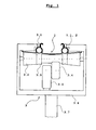
- the mounting device 3 knows each groove 1.1 of theticianleitprofils 1 in which a pipe 2 is clamped, at least three rollers 3.1, 3.2 3.3, whose rolling direction is aligned parallel to the profile direction of the sauitprofils 1.
- the two rollers 3.1, 3.2 are arranged at an axial distance from each other and press with their lateral surfaces with respect to the plane of the opening of the groove 1.1 from different sides to the heat transfer 1.
- the longitudinal section of a groove 1.1 located in the vicinity of this pair of rollers is widened so that its opening area there is at least approximately as wide as the diameter of the tube 2 if this is not deformed.
- the lateral surface of the third roller 3.3 is designed waisted and it protrudes at the opening surface of the groove 1.1.
- the tube 2 extends at the side facing the groove 1.1 side of the lateral surface of the roller 3.3.
- rollers 3.2 and 3.3 are arranged on a common axis, combined to form a common reel body and driven by a motor.
- the drive includes a motor 3.5 and a driven by this friction wheel 3.4 which rests with its peripheral surface on said roller body.
- Drive and rollers are held in an approximately C-shaped housing 3.6, which in turn is held on a stem 3.7, through which passes the power supply for the drive.
- the handle 3.7 the device be held and guided by a human and attached to an already on the ceiling of a room suspended heat conduction 1.
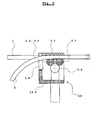
- the device 13 moves from Fig. 2 according to Fig. 2 from right to left.
- the device 13 is opposite to that of Fig. 1 supplemented by additional roles.
- roller 3.7 Just behind the roller 3.3, which introduces the tube 2 in the groove on the heat conduction and which presses with the roller 3.2 from below to the bathleitprofil, runs another roller 3.7, which also has a waisted lateral surface.
- the roller 3.7 presses on such a longitudinal region from the side of the slot opening of the shallleitprofils forth to the there located in the groove tube 2, at which the opening width of the groove on the heat conduction against the maximum expanded state is already slightly narrowed. The roller 3.7 thus ensures that the tube 2 is completely inserted into the groove.
- a set of rollers 3.8 is arranged with respect to the direction of movement of the device 13 on the furnishedleitprofil 1 in front of the roller 3.3, through which the tube 2 is introduced into the groove on the réelleleitprofil.
- the axes of rotation do not have to be parallel to the already discussed roles, a not yet clamped in the groove on the heat conduction longitudinal region of the clamped pipe 2 is directed him optimizing location and direction for further processing.
- the device according to the invention is particularly applicable to plantetprofilen, which are designed so that the serving for receiving in each case a tube grooves are particularly easy elastically expandable to bring the tube.
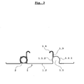
- Fig. 4 shows a section of a primafils 13 which is well produced by extrusion of aluminum. It has two respectively two-layer wall portions 11.3, 11.13, which is determined by the groove 11.1 which is intended for receiving a tube, project, and divide the boundary of the groove 11.1 in three surface areas 11.1.1, 11.1.2, 11.1.3, by the narrow gap between the two layers of a wall portion 11.3, 11.13 opens into the groove 11.1.
- a division of the Nutbegrenzung in only two sub-areas is the division of the Nutbegrenzung in three sub-areas, the opening of the groove 11.1 on and softer elastically expandable.
- the neutron-senor filament 13 has a profile wall 11.23, which protrudes from the wall portion 11.3 and just above the free end of the wall portion 11.13 protrudes.
- the profile wall 11.23 is connected only via a very thin web, so that the profile wall 11.23 against the wall portion 11.13 by plastic deformation of the thin web is pivotable without much effort.
- the profile wall 11.23 is pivoted downwards around the narrow connecting web to the wall region 11.3 so that its free end strikes the free end of the wall region 11.13 , while the wall portion 11.13 bends slightly away from the wall portion 11.3 away and finally locked at an angle range 11.13.1 of the wall portion.
- the process of pivoting the profile wall 11.23 can be achieved by another role of a device according to the invention, which is behind the rollers, which cause the insertion of the tube and presses from above on the profile wall 11.23.
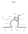
- Fig. 5 shows a section of another rectifierfils 21 which is well produced by extrusion of aluminum and on which devices of the invention are well applicable. Also, this heat conduction profile has two two-layer wall portions 21.3, 21.13 through which the boundary surface of the groove 21.1 in which a pipe is clamped is divided into three sub-areas.
- the skilletleitprofil has two profile walls 21.23, which from the outside of the central boundary surface of the groove 21.1 in the vicinity of each of a two-layered Wall area 21.3, 21.13 protrude.
- the two wall regions 21.23 are bent by mechanical action about their junction with the boundary surface of the groove 21.1 so that they abut with their free end against the respective wall region 21.3, 21.13, deflecting them slightly and thereby engage the wall area 21.3 or 21.13.
- this results in a better contact between the tube and the boundary surfaces of the groove.
- the bending of the wall portions 21.23 can also be done by a device according to the invention.
- the rollers 3.1 would have to be made so narrow that they would fit between the foot points of the profile walls 21.23 on the outside of the boundary surface of the groove 21.1.
- the direction of movement of the device behind the rollers 3.1 is at about the same height and with the axes of the rollers 3.1 parallel axis alignment another role to install.
- the profile walls 21.23 must be bent in the manner discussed.
- this additional role must be so long that it rests against one of the foot points of the profile walls 21.23 remote wall portion of this profile walls and pushes down there.
- a roller which causes the widening of the opening of the groove relative to that role with waisted lateral surface, through which a tube is inserted into a groove of the varnishleitprofils, with respect to the direction of travel of the device at the bathleitprofil be slightly further forward , This facilitates the introduction of the tube into the groove.
- an additional set of rollers may be provided, which is arranged on the device behind the previously discussed sets of rollers and serves to any unwanted plastic deformation of the shallleitprofils and / or of the tube through the front Roll set were caused to undo again.
Landscapes
- Engineering & Computer Science (AREA)
- Mechanical Engineering (AREA)
- General Engineering & Computer Science (AREA)
- Thermal Sciences (AREA)
- Chemical & Material Sciences (AREA)
- Combustion & Propulsion (AREA)
- Physics & Mathematics (AREA)
- Steam Or Hot-Water Central Heating Systems (AREA)
- Supports For Pipes And Cables (AREA)
- Resistance Heating (AREA)
- Conveying And Assembling Of Building Elements In Situ (AREA)
- Thermotherapy And Cooling Therapy Devices (AREA)
- Orthopedics, Nursing, And Contraception (AREA)
- Heat Treatment Of Articles (AREA)
Priority Applications (4)
| Application Number | Priority Date | Filing Date | Title |
|---|---|---|---|
| SI201331175T SI2653790T1 (sl) | 2012-04-19 | 2013-04-16 | Naprava za montažo cevi v utor toplotno prevodnega profila |
| PL13001976T PL2653790T3 (pl) | 2012-04-19 | 2013-04-16 | Urządzenie do montażu rury we wpuście profilu przewodzącego ciepło |
| RS20181125A RS57832B1 (sr) | 2012-04-19 | 2013-04-16 | Uređaj za montiranje cevi u žleb profila za prenos toplote |
| HRP20181522TT HRP20181522T1 (hr) | 2012-04-19 | 2018-09-26 | Uređaj za montažu cijevi u žlijeb profila za toplinsku vodljivost |
Applications Claiming Priority (1)
| Application Number | Priority Date | Filing Date | Title |
|---|---|---|---|
| ATA481/2012A AT511960B1 (de) | 2012-04-19 | 2012-04-19 | Vorrichtung für die Montage eines Rohres in einer Nut eines Wärmeleitprofils |
Publications (3)
| Publication Number | Publication Date |
|---|---|
| EP2653790A2 true EP2653790A2 (fr) | 2013-10-23 |
| EP2653790A3 EP2653790A3 (fr) | 2016-02-10 |
| EP2653790B1 EP2653790B1 (fr) | 2018-06-27 |
Family
ID=48190009
Family Applications (1)
| Application Number | Title | Priority Date | Filing Date |
|---|---|---|---|
| EP13001976.3A Active EP2653790B1 (fr) | 2012-04-19 | 2013-04-16 | Dispositif destiné au montage d'un tube dans une rainure d'un profil conducteur de chaleur |
Country Status (9)
| Country | Link |
|---|---|
| EP (1) | EP2653790B1 (fr) |
| AT (1) | AT511960B1 (fr) |
| DK (1) | DK2653790T3 (fr) |
| ES (1) | ES2687441T3 (fr) |
| HR (1) | HRP20181522T1 (fr) |
| HU (1) | HUE040633T2 (fr) |
| PL (1) | PL2653790T3 (fr) |
| RS (1) | RS57832B1 (fr) |
| SI (1) | SI2653790T1 (fr) |
Cited By (2)
| Publication number | Priority date | Publication date | Assignee | Title |
|---|---|---|---|---|
| CN105922186A (zh) * | 2016-05-30 | 2016-09-07 | 中国铁建大桥工程局集团有限公司 | 一种密封胶条安装器及安装方法 |
| AT527060B1 (de) * | 2024-01-18 | 2024-10-15 | Ke Kelit Gmbh | Halteschiene zur Befestigung an Trockenbauprofilen |
Citations (5)
| Publication number | Priority date | Publication date | Assignee | Title |
|---|---|---|---|---|
| EP0733866A2 (fr) | 1995-03-21 | 1996-09-25 | GIACOMINI Services and Engineering SA | Plafond pour chauffage ou pour refroidissement |
| DE20106884U1 (de) | 2001-04-20 | 2001-06-21 | Lindner AG, 94424 Arnstorf | Deckenaufbau |
| DE19803114C2 (de) | 1998-01-28 | 2002-08-08 | Emcal Waermesysteme Gmbh | Wärmetauscherdecke mit Wärmeleitelementen |
| DE102004057384B4 (de) | 2004-11-26 | 2008-06-26 | Peuckert Gmbh | Wärmeleitprofil sowie Verwendung davon |
| WO2010121283A2 (fr) | 2009-04-23 | 2010-10-28 | Lindner Gmbh | Profilé thermoconducteur |
Family Cites Families (4)
| Publication number | Priority date | Publication date | Assignee | Title |
|---|---|---|---|---|
| US6340271B1 (en) * | 1999-02-26 | 2002-01-22 | Wireline Technologies, Inc. | Conduit cable feeding sheave |
| US6915549B2 (en) * | 2002-07-20 | 2005-07-12 | Bellsouth Intellectual Property Corporation | Tool for installing communication cable in a cleft |
| JP3723188B2 (ja) * | 2003-05-20 | 2005-12-07 | 株式会社プラ技研 | 暖房用マットにおける温水流通用チューブ構造 |
| US20040258480A1 (en) * | 2003-06-19 | 2004-12-23 | Prisby James V. | Conduit installation tool and method of use thereof |
-
2012
- 2012-04-19 AT ATA481/2012A patent/AT511960B1/de not_active IP Right Cessation
-
2013
- 2013-04-16 ES ES13001976.3T patent/ES2687441T3/es active Active
- 2013-04-16 SI SI201331175T patent/SI2653790T1/sl unknown
- 2013-04-16 EP EP13001976.3A patent/EP2653790B1/fr active Active
- 2013-04-16 PL PL13001976T patent/PL2653790T3/pl unknown
- 2013-04-16 RS RS20181125A patent/RS57832B1/sr unknown
- 2013-04-16 DK DK13001976.3T patent/DK2653790T3/en active
- 2013-04-16 HU HUE13001976A patent/HUE040633T2/hu unknown
-
2018
- 2018-09-26 HR HRP20181522TT patent/HRP20181522T1/hr unknown
Patent Citations (5)
| Publication number | Priority date | Publication date | Assignee | Title |
|---|---|---|---|---|
| EP0733866A2 (fr) | 1995-03-21 | 1996-09-25 | GIACOMINI Services and Engineering SA | Plafond pour chauffage ou pour refroidissement |
| DE19803114C2 (de) | 1998-01-28 | 2002-08-08 | Emcal Waermesysteme Gmbh | Wärmetauscherdecke mit Wärmeleitelementen |
| DE20106884U1 (de) | 2001-04-20 | 2001-06-21 | Lindner AG, 94424 Arnstorf | Deckenaufbau |
| DE102004057384B4 (de) | 2004-11-26 | 2008-06-26 | Peuckert Gmbh | Wärmeleitprofil sowie Verwendung davon |
| WO2010121283A2 (fr) | 2009-04-23 | 2010-10-28 | Lindner Gmbh | Profilé thermoconducteur |
Cited By (4)
| Publication number | Priority date | Publication date | Assignee | Title |
|---|---|---|---|---|
| CN105922186A (zh) * | 2016-05-30 | 2016-09-07 | 中国铁建大桥工程局集团有限公司 | 一种密封胶条安装器及安装方法 |
| CN105922186B (zh) * | 2016-05-30 | 2018-03-06 | 中国铁建大桥工程局集团有限公司 | 一种密封胶条安装器及安装方法 |
| AT527060B1 (de) * | 2024-01-18 | 2024-10-15 | Ke Kelit Gmbh | Halteschiene zur Befestigung an Trockenbauprofilen |
| AT527060A4 (de) * | 2024-01-18 | 2024-10-15 | Ke Kelit Gmbh | Halteschiene zur Befestigung an Trockenbauprofilen |
Also Published As
| Publication number | Publication date |
|---|---|
| ES2687441T3 (es) | 2018-10-25 |
| RS57832B1 (sr) | 2018-12-31 |
| DK2653790T3 (en) | 2018-10-15 |
| HUE040633T2 (hu) | 2019-03-28 |
| AT511960B1 (de) | 2013-04-15 |
| SI2653790T1 (sl) | 2018-10-30 |
| EP2653790B1 (fr) | 2018-06-27 |
| EP2653790A3 (fr) | 2016-02-10 |
| AT511960A4 (de) | 2013-04-15 |
| PL2653790T3 (pl) | 2018-11-30 |
| HRP20181522T1 (hr) | 2018-11-16 |
Similar Documents
| Publication | Publication Date | Title |
|---|---|---|
| DE69318556T2 (de) | Klemmbacke | |
| DE3432073A1 (de) | Waermetauscher, insbesondere fuer kraftfahrzeuge, und vorrichtung und verfahren zum verbinden von dessen rohren und lamellen | |
| DE2755695C3 (de) | Wärmegedämmtes Verbundprofil für Fenster, Türen u.dgl. | |
| DE202011051396U1 (de) | Profilummantelungsmaschine | |
| CH669130A5 (de) | Verfahren und vorrichtung zum runden von blechen, insbesondere fuer dosenkoerper. | |
| DE102007062104B4 (de) | Vorrichtung für einen Rollformer zum Profilieren eines Blechbandes und dazugehöriges Verfahren | |
| DE2221179A1 (de) | Mehrteiliger rahmen, insbesondere fenster- oder tuerrahmen | |
| EP2435195B1 (fr) | Procédé et dispositif de profilage en continu | |
| EP2653790B1 (fr) | Dispositif destiné au montage d'un tube dans une rainure d'un profil conducteur de chaleur | |
| EP0537594A2 (fr) | Procédé de formation d'un profilé à raccord à brides; profilé à raccord à brides en particulier pour des installations de canalisations d'air | |
| EP2653792B1 (fr) | Profil conducteur de chaleur | |
| EP3786532B1 (fr) | Échangeur de chaleur de surface, système et procédé | |
| DE102013018189A1 (de) | Entwässerungsvorrichtung für Förderbänder | |
| DE19912915C1 (de) | Lüftungsgitterprofil aus Metall und Verfahren zu dessen Herstellung | |
| CH652188A5 (en) | Composite profile | |
| DE9202767U1 (de) | Endliches Bewehrungselement zur Bewehrung von Betonteilen, sowie Vorrichtung zu dessen Herstellung | |
| DE102006040519B4 (de) | Verfahren zur Herstellung einer Stromschiene | |
| DE3427369C2 (fr) | ||
| DE3926472C1 (fr) | ||
| DE3515256A1 (de) | Einschub- und kabelziehgeraet fuer zwischenboden und kunststoffstab mit gliedbandfuehrung | |
| DE10331812B4 (de) | Stabförmiges Betätigungselement zum Übertragen von Druckkräften | |
| DE1602522C3 (de) | Vorrichtung zum Walzen von mit Querrippen versehenen Blechen | |
| EP4650064A1 (fr) | Boitier de cage avec surfaces de support pour baguettes coulissantes | |
| DE2008277A1 (en) | Spiral grooved flexible tube mfe | |
| EP3323955A1 (fr) | Support profilé en acier |
Legal Events
| Date | Code | Title | Description |
|---|---|---|---|
| PUAI | Public reference made under article 153(3) epc to a published international application that has entered the european phase |
Free format text: ORIGINAL CODE: 0009012 |
|
| AK | Designated contracting states |
Kind code of ref document: A2 Designated state(s): AL AT BE BG CH CY CZ DE DK EE ES FI FR GB GR HR HU IE IS IT LI LT LU LV MC MK MT NL NO PL PT RO RS SE SI SK SM TR |
|
| AX | Request for extension of the european patent |
Extension state: BA ME |
|
| PUAL | Search report despatched |
Free format text: ORIGINAL CODE: 0009013 |
|
| AK | Designated contracting states |
Kind code of ref document: A3 Designated state(s): AL AT BE BG CH CY CZ DE DK EE ES FI FR GB GR HR HU IE IS IT LI LT LU LV MC MK MT NL NO PL PT RO RS SE SI SK SM TR |
|
| AX | Request for extension of the european patent |
Extension state: BA ME |
|
| RIC1 | Information provided on ipc code assigned before grant |
Ipc: F24D 3/14 20060101AFI20160105BHEP Ipc: B65H 49/32 20060101ALI20160105BHEP Ipc: B25B 27/00 20060101ALI20160105BHEP |
|
| RBV | Designated contracting states (corrected) |
Designated state(s): AL AT BE BG CH CY CZ DE DK EE ES FI FR GB GR HR HU IE IS IT LI LT LU LV MC MK MT NL NO PL PT RO RS SE SI SK SM TR |
|
| 17P | Request for examination filed |
Effective date: 20160801 |
|
| RBV | Designated contracting states (corrected) |
Designated state(s): AL AT BE BG CH CY CZ DE DK EE ES FI FR GB GR HR HU IE IS IT LI LT LU LV MC MK MT NL NO PL PT RO RS SE SI SK SM TR |
|
| RIC1 | Information provided on ipc code assigned before grant |
Ipc: F24D 3/14 20060101AFI20171221BHEP Ipc: B25B 27/00 20060101ALI20171221BHEP Ipc: B65H 49/32 20060101ALI20171221BHEP |
|
| GRAP | Despatch of communication of intention to grant a patent |
Free format text: ORIGINAL CODE: EPIDOSNIGR1 |
|
| STAA | Information on the status of an ep patent application or granted ep patent |
Free format text: STATUS: GRANT OF PATENT IS INTENDED |
|
| INTG | Intention to grant announced |
Effective date: 20180214 |
|
| GRAS | Grant fee paid |
Free format text: ORIGINAL CODE: EPIDOSNIGR3 |
|
| GRAA | (expected) grant |
Free format text: ORIGINAL CODE: 0009210 |
|
| STAA | Information on the status of an ep patent application or granted ep patent |
Free format text: STATUS: THE PATENT HAS BEEN GRANTED |
|
| AK | Designated contracting states |
Kind code of ref document: B1 Designated state(s): AL AT BE BG CH CY CZ DE DK EE ES FI FR GB GR HR HU IE IS IT LI LT LU LV MC MK MT NL NO PL PT RO RS SE SI SK SM TR |
|
| REG | Reference to a national code |
Ref country code: GB Ref legal event code: FG4D Free format text: NOT ENGLISH |
|
| REG | Reference to a national code |
Ref country code: AT Ref legal event code: REF Ref document number: 1012672 Country of ref document: AT Kind code of ref document: T Effective date: 20180715 |
|
| REG | Reference to a national code |
Ref country code: IE Ref legal event code: FG4D Free format text: LANGUAGE OF EP DOCUMENT: GERMAN |
|
| REG | Reference to a national code |
Ref country code: DE Ref legal event code: R096 Ref document number: 502013010447 Country of ref document: DE |
|
| REG | Reference to a national code |
Ref country code: RO Ref legal event code: EPE |
|
| REG | Reference to a national code |
Ref country code: HR Ref legal event code: TUEP Ref document number: P20181522 Country of ref document: HR |
|
| REG | Reference to a national code |
Ref country code: NL Ref legal event code: FP |
|
| REG | Reference to a national code |
Ref country code: DK Ref legal event code: T3 Effective date: 20181008 |
|
| REG | Reference to a national code |
Ref country code: ES Ref legal event code: FG2A Ref document number: 2687441 Country of ref document: ES Kind code of ref document: T3 Effective date: 20181025 |
|
| PG25 | Lapsed in a contracting state [announced via postgrant information from national office to epo] |
Ref country code: SE Free format text: LAPSE BECAUSE OF FAILURE TO SUBMIT A TRANSLATION OF THE DESCRIPTION OR TO PAY THE FEE WITHIN THE PRESCRIBED TIME-LIMIT Effective date: 20180627 Ref country code: FI Free format text: LAPSE BECAUSE OF FAILURE TO SUBMIT A TRANSLATION OF THE DESCRIPTION OR TO PAY THE FEE WITHIN THE PRESCRIBED TIME-LIMIT Effective date: 20180627 Ref country code: NO Free format text: LAPSE BECAUSE OF FAILURE TO SUBMIT A TRANSLATION OF THE DESCRIPTION OR TO PAY THE FEE WITHIN THE PRESCRIBED TIME-LIMIT Effective date: 20180927 Ref country code: LT Free format text: LAPSE BECAUSE OF FAILURE TO SUBMIT A TRANSLATION OF THE DESCRIPTION OR TO PAY THE FEE WITHIN THE PRESCRIBED TIME-LIMIT Effective date: 20180627 Ref country code: BG Free format text: LAPSE BECAUSE OF FAILURE TO SUBMIT A TRANSLATION OF THE DESCRIPTION OR TO PAY THE FEE WITHIN THE PRESCRIBED TIME-LIMIT Effective date: 20180927 |
|
| REG | Reference to a national code |
Ref country code: LT Ref legal event code: MG4D |
|
| REG | Reference to a national code |
Ref country code: HR Ref legal event code: T1PR Ref document number: P20181522 Country of ref document: HR |
|
| PG25 | Lapsed in a contracting state [announced via postgrant information from national office to epo] |
Ref country code: GR Free format text: LAPSE BECAUSE OF FAILURE TO SUBMIT A TRANSLATION OF THE DESCRIPTION OR TO PAY THE FEE WITHIN THE PRESCRIBED TIME-LIMIT Effective date: 20180928 Ref country code: LV Free format text: LAPSE BECAUSE OF FAILURE TO SUBMIT A TRANSLATION OF THE DESCRIPTION OR TO PAY THE FEE WITHIN THE PRESCRIBED TIME-LIMIT Effective date: 20180627 |
|
| REG | Reference to a national code |
Ref country code: SK Ref legal event code: T3 Ref document number: E 28522 Country of ref document: SK |
|
| PG25 | Lapsed in a contracting state [announced via postgrant information from national office to epo] |
Ref country code: IS Free format text: LAPSE BECAUSE OF FAILURE TO SUBMIT A TRANSLATION OF THE DESCRIPTION OR TO PAY THE FEE WITHIN THE PRESCRIBED TIME-LIMIT Effective date: 20181027 Ref country code: EE Free format text: LAPSE BECAUSE OF FAILURE TO SUBMIT A TRANSLATION OF THE DESCRIPTION OR TO PAY THE FEE WITHIN THE PRESCRIBED TIME-LIMIT Effective date: 20180627 |
|
| PG25 | Lapsed in a contracting state [announced via postgrant information from national office to epo] |
Ref country code: SM Free format text: LAPSE BECAUSE OF FAILURE TO SUBMIT A TRANSLATION OF THE DESCRIPTION OR TO PAY THE FEE WITHIN THE PRESCRIBED TIME-LIMIT Effective date: 20180627 |
|
| REG | Reference to a national code |
Ref country code: HU Ref legal event code: AG4A Ref document number: E040633 Country of ref document: HU Ref country code: DE Ref legal event code: R097 Ref document number: 502013010447 Country of ref document: DE |
|
| PLBE | No opposition filed within time limit |
Free format text: ORIGINAL CODE: 0009261 |
|
| REG | Reference to a national code |
Ref country code: HR Ref legal event code: ODRP Ref document number: P20181522 Country of ref document: HR Payment date: 20190411 Year of fee payment: 7 |
|
| STAA | Information on the status of an ep patent application or granted ep patent |
Free format text: STATUS: NO OPPOSITION FILED WITHIN TIME LIMIT |
|
| 26N | No opposition filed |
Effective date: 20190328 |
|
| PG25 | Lapsed in a contracting state [announced via postgrant information from national office to epo] |
Ref country code: AL Free format text: LAPSE BECAUSE OF FAILURE TO SUBMIT A TRANSLATION OF THE DESCRIPTION OR TO PAY THE FEE WITHIN THE PRESCRIBED TIME-LIMIT Effective date: 20180627 |
|
| PG25 | Lapsed in a contracting state [announced via postgrant information from national office to epo] |
Ref country code: MC Free format text: LAPSE BECAUSE OF FAILURE TO SUBMIT A TRANSLATION OF THE DESCRIPTION OR TO PAY THE FEE WITHIN THE PRESCRIBED TIME-LIMIT Effective date: 20180627 |
|
| PG25 | Lapsed in a contracting state [announced via postgrant information from national office to epo] |
Ref country code: TR Free format text: LAPSE BECAUSE OF FAILURE TO SUBMIT A TRANSLATION OF THE DESCRIPTION OR TO PAY THE FEE WITHIN THE PRESCRIBED TIME-LIMIT Effective date: 20180627 |
|
| PG25 | Lapsed in a contracting state [announced via postgrant information from national office to epo] |
Ref country code: IE Free format text: LAPSE BECAUSE OF NON-PAYMENT OF DUE FEES Effective date: 20190416 |
|
| REG | Reference to a national code |
Ref country code: HR Ref legal event code: ODRP Ref document number: P20181522 Country of ref document: HR Payment date: 20200406 Year of fee payment: 8 |
|
| PG25 | Lapsed in a contracting state [announced via postgrant information from national office to epo] |
Ref country code: PT Free format text: LAPSE BECAUSE OF FAILURE TO SUBMIT A TRANSLATION OF THE DESCRIPTION OR TO PAY THE FEE WITHIN THE PRESCRIBED TIME-LIMIT Effective date: 20181029 |
|
| PG25 | Lapsed in a contracting state [announced via postgrant information from national office to epo] |
Ref country code: RO Free format text: LAPSE BECAUSE OF NON-PAYMENT OF DUE FEES Effective date: 20200416 |
|
| PG25 | Lapsed in a contracting state [announced via postgrant information from national office to epo] |
Ref country code: RS Free format text: LAPSE BECAUSE OF NON-PAYMENT OF DUE FEES Effective date: 20200416 |
|
| REG | Reference to a national code |
Ref country code: HR Ref legal event code: ODRP Ref document number: P20181522 Country of ref document: HR Payment date: 20210413 Year of fee payment: 9 |
|
| PG25 | Lapsed in a contracting state [announced via postgrant information from national office to epo] |
Ref country code: CY Free format text: LAPSE BECAUSE OF FAILURE TO SUBMIT A TRANSLATION OF THE DESCRIPTION OR TO PAY THE FEE WITHIN THE PRESCRIBED TIME-LIMIT Effective date: 20180627 |
|
| PG25 | Lapsed in a contracting state [announced via postgrant information from national office to epo] |
Ref country code: MT Free format text: LAPSE BECAUSE OF FAILURE TO SUBMIT A TRANSLATION OF THE DESCRIPTION OR TO PAY THE FEE WITHIN THE PRESCRIBED TIME-LIMIT Effective date: 20180627 |
|
| REG | Reference to a national code |
Ref country code: HR Ref legal event code: ODRP Ref document number: P20181522 Country of ref document: HR Payment date: 20220412 Year of fee payment: 10 |
|
| PG25 | Lapsed in a contracting state [announced via postgrant information from national office to epo] |
Ref country code: MK Free format text: LAPSE BECAUSE OF FAILURE TO SUBMIT A TRANSLATION OF THE DESCRIPTION OR TO PAY THE FEE WITHIN THE PRESCRIBED TIME-LIMIT Effective date: 20180627 |
|
| REG | Reference to a national code |
Ref country code: HR Ref legal event code: ODRP Ref document number: P20181522 Country of ref document: HR Payment date: 20230411 Year of fee payment: 11 |
|
| P01 | Opt-out of the competence of the unified patent court (upc) registered |
Effective date: 20230620 |
|
| PGFP | Annual fee paid to national office [announced via postgrant information from national office to epo] |
Ref country code: GB Payment date: 20230419 Year of fee payment: 11 |
|
| REG | Reference to a national code |
Ref country code: HR Ref legal event code: ODRP Ref document number: P20181522 Country of ref document: HR Payment date: 20240404 Year of fee payment: 12 |
|
| PGFP | Annual fee paid to national office [announced via postgrant information from national office to epo] |
Ref country code: DK Payment date: 20240423 Year of fee payment: 12 |
|
| PGFP | Annual fee paid to national office [announced via postgrant information from national office to epo] |
Ref country code: HR Payment date: 20240404 Year of fee payment: 12 |
|
| GBPC | Gb: european patent ceased through non-payment of renewal fee |
Effective date: 20240416 |
|
| PG25 | Lapsed in a contracting state [announced via postgrant information from national office to epo] |
Ref country code: GB Free format text: LAPSE BECAUSE OF NON-PAYMENT OF DUE FEES Effective date: 20240416 |
|
| PG25 | Lapsed in a contracting state [announced via postgrant information from national office to epo] |
Ref country code: GB Free format text: LAPSE BECAUSE OF NON-PAYMENT OF DUE FEES Effective date: 20240416 |
|
| PGFP | Annual fee paid to national office [announced via postgrant information from national office to epo] |
Ref country code: SI Payment date: 20250403 Year of fee payment: 13 |
|
| PGFP | Annual fee paid to national office [announced via postgrant information from national office to epo] |
Ref country code: NL Payment date: 20250418 Year of fee payment: 13 |
|
| PGFP | Annual fee paid to national office [announced via postgrant information from national office to epo] |
Ref country code: LU Payment date: 20250418 Year of fee payment: 13 |
|
| PGFP | Annual fee paid to national office [announced via postgrant information from national office to epo] |
Ref country code: PL Payment date: 20250403 Year of fee payment: 13 Ref country code: DE Payment date: 20250422 Year of fee payment: 13 |
|
| PGFP | Annual fee paid to national office [announced via postgrant information from national office to epo] |
Ref country code: ES Payment date: 20250529 Year of fee payment: 13 |
|
| PGFP | Annual fee paid to national office [announced via postgrant information from national office to epo] |
Ref country code: IT Payment date: 20250424 Year of fee payment: 13 Ref country code: BE Payment date: 20250418 Year of fee payment: 13 |
|
| PGFP | Annual fee paid to national office [announced via postgrant information from national office to epo] |
Ref country code: FR Payment date: 20250425 Year of fee payment: 13 |
|
| PGFP | Annual fee paid to national office [announced via postgrant information from national office to epo] |
Ref country code: CH Payment date: 20250501 Year of fee payment: 13 |
|
| PGFP | Annual fee paid to national office [announced via postgrant information from national office to epo] |
Ref country code: AT Payment date: 20250423 Year of fee payment: 13 |
|
| PGFP | Annual fee paid to national office [announced via postgrant information from national office to epo] |
Ref country code: SK Payment date: 20250407 Year of fee payment: 13 |
|
| PGFP | Annual fee paid to national office [announced via postgrant information from national office to epo] |
Ref country code: CZ Payment date: 20250407 Year of fee payment: 13 |
|
| REG | Reference to a national code |
Ref country code: HR Ref legal event code: PBON Ref document number: P20181522 Country of ref document: HR Effective date: 20250416 |
|
| PGFP | Annual fee paid to national office [announced via postgrant information from national office to epo] |
Ref country code: HU Payment date: 20251008 Year of fee payment: 13 |
|
| REG | Reference to a national code |
Ref country code: DK Ref legal event code: EBP Effective date: 20250430 |
|
| PG25 | Lapsed in a contracting state [announced via postgrant information from national office to epo] |
Ref country code: HR Free format text: LAPSE BECAUSE OF NON-PAYMENT OF DUE FEES Effective date: 20250416 |