EP2651804B1 - Energy efficient elevator installation - Google Patents
Energy efficient elevator installation Download PDFInfo
- Publication number
- EP2651804B1 EP2651804B1 EP20110788799 EP11788799A EP2651804B1 EP 2651804 B1 EP2651804 B1 EP 2651804B1 EP 20110788799 EP20110788799 EP 20110788799 EP 11788799 A EP11788799 A EP 11788799A EP 2651804 B1 EP2651804 B1 EP 2651804B1
- Authority
- EP
- European Patent Office
- Prior art keywords
- control unit
- energy consumption
- lift
- storey
- elevator
- Prior art date
- Legal status (The legal status is an assumption and is not a legal conclusion. Google has not performed a legal analysis and makes no representation as to the accuracy of the status listed.)
- Active
Links
- 238000009434 installation Methods 0.000 title claims description 38
- 238000005265 energy consumption Methods 0.000 claims description 50
- 238000000034 method Methods 0.000 claims description 20
- 230000008859 change Effects 0.000 claims description 8
- 230000006870 function Effects 0.000 description 7
- 238000004891 communication Methods 0.000 description 3
- 230000008901 benefit Effects 0.000 description 2
- 230000007613 environmental effect Effects 0.000 description 2
- 238000012545 processing Methods 0.000 description 2
- 238000011160 research Methods 0.000 description 2
- 238000013459 approach Methods 0.000 description 1
- 230000001276 controlling effect Effects 0.000 description 1
- 230000001419 dependent effect Effects 0.000 description 1
- 238000001514 detection method Methods 0.000 description 1
- 238000005259 measurement Methods 0.000 description 1
- 230000008569 process Effects 0.000 description 1
- 230000009467 reduction Effects 0.000 description 1
- 230000001105 regulatory effect Effects 0.000 description 1
Images


Classifications
-
- B—PERFORMING OPERATIONS; TRANSPORTING
- B66—HOISTING; LIFTING; HAULING
- B66B—ELEVATORS; ESCALATORS OR MOVING WALKWAYS
- B66B1/00—Control systems of elevators in general
- B66B1/24—Control systems with regulation, i.e. with retroactive action, for influencing travelling speed, acceleration, or deceleration
- B66B1/2408—Control systems with regulation, i.e. with retroactive action, for influencing travelling speed, acceleration, or deceleration where the allocation of a call to an elevator car is of importance, i.e. by means of a supervisory or group controller
- B66B1/2433—For elevator systems with a single shaft and multiple cars
-
- Y—GENERAL TAGGING OF NEW TECHNOLOGICAL DEVELOPMENTS; GENERAL TAGGING OF CROSS-SECTIONAL TECHNOLOGIES SPANNING OVER SEVERAL SECTIONS OF THE IPC; TECHNICAL SUBJECTS COVERED BY FORMER USPC CROSS-REFERENCE ART COLLECTIONS [XRACs] AND DIGESTS
- Y02—TECHNOLOGIES OR APPLICATIONS FOR MITIGATION OR ADAPTATION AGAINST CLIMATE CHANGE
- Y02B—CLIMATE CHANGE MITIGATION TECHNOLOGIES RELATED TO BUILDINGS, e.g. HOUSING, HOUSE APPLIANCES OR RELATED END-USER APPLICATIONS
- Y02B50/00—Energy efficient technologies in elevators, escalators and moving walkways, e.g. energy saving or recuperation technologies
Definitions
- the invention relates to a method for operating a lift system comprising a control unit and at least one elevator car in a building with at least three storeys.
- EP1876129A1 describes a method for reducing the energy consumption of an elevator installation.
- the elevator system is alternatively brought into an operation mode or in a stand-by mode.
- the highest energy consumption occurs in the operation mode, while the power consumption is lower in the stand-by mode.
- detection means a user criterion of the elevator installation, such as a presence of a passenger in an elevator car is detected.
- Stand-by criteria such as periods of low traffic are also defined. As long as the stand-by criteria are not met, the elevator installation will be left in operation mode. As soon as the stand-by criteria are met and the usage criterion is not met, the elevator system is put into stand-by mode.
- the WO 2010/086290 A1 describes a method for energy-saving operation of an elevator installation, wherein energy consumption of at least one energy consumer of the elevator system is detected, at least one traffic situation of the elevator system is detected, for the detected energy consumption and the detected traffic situation at least one energy value is determined and the determined energy consumption value on at least one output means is issued.
- EP 1 553 038 A1 discloses a method according to the preamble of claim 1 and an elevator installation according to the preamble of claim 6.
- Another possibility for reducing the energy consumption of elevator systems is that the elevator system is brought into a standby mode when not in use. This means that, for example, superfluous lighting, displays, control units or other elevator components are temporarily switched off. If a drive request, the elevator system wakes up and performs the elevator ride, but without taking into account the energy consumption of the elevator ride.
- the waiting mode in elevator systems may have the disadvantage that the time interval between the waiting mode and operational readiness of the elevator installation can be relatively long.
- An object of the invention is to propose a further possibility for a cost-effective and efficient reduction of the energy consumption of an elevator installation.
- a core of the invention is that of a control unit of an elevator installation in a building with at least three floors each an energy consumption value of the elevator system for the arrival of a current holding floor of an elevator car elevator system to at least one input destination and each at least one entered trip request floor is determined. In this case, the destination or travel request floor is approached by the elevator car, in which the at least one energy consumption value of the elevator installation is minimal.
- the elevator car is moved between the at least three floors. On at least two floors is ever arranged an elevator control unit for entering a travel request. Of course, an elevator operating unit could also be arranged on each floor.
- the method provides that the control unit receives a travel request from an elevator operating unit arranged on the at least two storeys. Either by the input to the elevator control unit or by an input to a control unit in the elevator car which transmits the input to the control unit, a destination floor is defined and the input is executed by the control unit. The control unit thus receives an indication a destination floor. The at least one input travel request is executed by the control unit by means of a collection mode.
- the direction of travel of the elevator car is changed by the control unit as a function of the determined energy consumption values.
- the elevator car could be moved one floor lower before continuing upwards.
- the elevator car is thus not only moved upwards or downwards during a collective journey in the collective mode of operation, but is moved both downwards and upwards as a function of ascertained energy consumption values.
- the travel scheme or the travel curve therefore has a zig-zag course in the collective mode of operation, ie the elevator car does not travel continuously upwards or downwards.
- the energy consumption values of the elevator installation can be determined or determined, for example, as a function of the payload in the elevator car, the direction of travel of the elevator car, etc.
- the sequence can be determined in such a way that the total energy consumption of the elevator installation in the approaching destination and destination request floors, ie the collective journey to be carried out in the collective mode, becomes minimal. It is also conceivable, moreover, that the energy consumption values are determined by a central unit in a service center and transmitted to the control unit of the elevator installation for further processing, eg, by a control unit. B. for determining the order of the hold to be performed on the entered destinations and travel requests forwarded.
- a driving scheme for the groupage to be performed is defined and executed by the control unit.
- This travel scheme may be stored, for example, in a memory unit which is connected to the control unit.
- the order of the destination and trip request floors to be approached may change during a collective journey. This is the case when, for example, in addition to the already registered destinations and travel requests another drive request is entered at a lift control unit on a floor.
- a floor to be approached can be determined as a function of a rule.
- a rule a wide variety of parameters, conditions, procedures, intervals, etc. are conceivable.
- several rules can be defined and z. B. be combined with each other.
- a rule for. B. a maximum time for an elevator ride from a start floor to a destination floor of a passenger are determined, the so-called. Service time. But also the waiting time of a passenger at a starting or driving request stick can be determined.
- the number of changes of direction, the times at which no change of direction to be performed, the maximum load of the elevator car, a number of maximum approached floors, the time, a number of already approached floors, etc. can be used as a rule.
- One advantage is the fact that the energy consumption of an elevator installation can only be reduced by controlling or coordinating the elevator trips to be carried out.
- Another advantage is that the method can also be used in existing elevator systems, since no structural measures have to be made in the components of an elevator installation. Only the control unit could need to be modified.
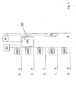
- FIG. 1 shows an inventive example of an elevator installation for carrying out the method as described in the Figures 3 and 4 ,
- a lift used with counterweight G there will be a lift used with counterweight G.
- a hydraulic elevator, a lift without counterweight, etc. can be used.
- the elevator car AK has an operating unit BE for entering a destination floor Z.
- each floor F has an elevator operating unit ABE, which are connected to a control unit SE via a suitable communication network, wired or non-wired.
- the operating unit BE in the elevator car AK is also connected to the control unit SE via a communication network, be it via its own or the same communication network as the elevator operating unit ABE.
- FIG. 12 shows an example of a known cruise scheme in a group trip in a collective mode.
- the approached floors F are plotted as a function of time t.
- the elevator journey or collection journey begins on the ground floor F, the 0th floor at time t, due to a travel request R1 entered into an elevator operating unit ABE and forwarded to a control unit SE, and is to end at the fifth floor, the destination floor Z1.
- the control unit SE initiates a stopover of the elevator car AK on this travel request floor F.
- the trip requested on the 3rd floor is likewise to end in the 5th floor.
- the elevator car AK moves empty to the driving request floor, the second floor, so that they can bring the passengers requesting the journey to the 6th floor, the destination floor Z2 this trip request R3.
- a destination floor Z can be done either via the elevator control unit ABE or via a control unit BE in the elevator car AK
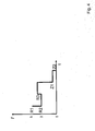
- FIG. 3 shows an example of a novel driving scheme.
- the collection journey starts at time t on the ground floor, the 0th floor, with a travel request R1, which was entered into an elevator operating unit ABE and transmitted to the control unit SE.
- the elevator car AK makes a stopover on the 3rd floor due to another trip request R2.
- another drive request R3 entered in an elevator operating unit ABE on the 2nd floor is registered by the control unit SE.
- control unit SE now determines at least one energy consumption value of the elevator installation for the approach from the current retaining floor, for example the third floor, the elevator car AK to the respective landing floor R3, in this example the second floor, and respectively to the destination floors Z1, Z2, in this example the 5th and the 6th floor.
- the destination or travel inquiry floor Z1, Z2, R3 is now approached, in which the at least one energy consumption value of the elevator installation is minimal.
- the energy consumption value of the elevator installation is minimal when approaching the 2nd floor.
- a change of direction takes place before the collection journey continues up to the destination floors Z1, Z2, to the 5th and 6th floor.
- the energy consumption values can be determined as a function of the payload in the elevator car AK, the direction of travel of the elevator car AK, etc.
- load both the current load existing in the elevator car AK and the estimated additional load due to the boarding of passengers on a travel request floor R1, R2, R3 can be used.
- the determination of the energy consumption values can be carried out using various methods, such as described in the lift report article "Assessment of the environmental impact of lifts during their service life" 03/2010. For example, the Energy consumption for a representative trip to be determined. In this case, individual energy consumption values, such as for an upward drive to the highest stop, a downward drive to the lower stop and the respective door operation (open and close), calculated. Based on the individual energy consumption values, the energy consumption of other journeys can then be determined. Taking into account a traffic pattern of an elevator installation, the total energy consumption of an elevator installation can be determined. Also, the energy consumption of an elevator installation can be determined from consumption measurements for each possible journey or based on simplified energy models.
- control unit SE determines an order of the destination and travel request floors Z1, Z2, R1, R2, R3 to be approached on the basis of the determined energy consumption values.
- the order of the destination and travel request floors Z1, Z2, R1, R2, R3 to be approached can be determined such that the total energy consumption of the elevator installation is minimized or reduced.
- the order may be stored in the form of a list, table etc. in a memory unit which is not shown in the figures.
- the storage unit is connected to the control unit SE and either integrated in the control unit or separated from it (SE).
- SE integrated in the control unit or separated from it
- a central unit determines the energy consumption values of the elevator installation and transmits it to the control unit SE for further processing or execution.
- the target and / or travel request blocks Z1, Z2, R1, R2, R3 to be approached can be determined by the control unit SE as a function of a rule.
- a rule basically all parameters, conditions, intervals, etc. can be used, which can provide an efficient elevator operation.
- a value or an interval for a service time can be determined.
- service time is meant the execution time of a requested elevator ride, from travel request floor R1, R2, R3 to the destination floor Z1, Z2. This generally increases when additional travel request floors are approached by the elevator car AK.
- the minimum and / or maximum waiting time of a passenger on a journey request floor could be defined according to a rule.
- a condition could indicate the times, for example the rush hours in a building, in which no change of direction is to be performed by the elevator installation.
- Another condition could be, for example, priority driving.
- Even minimum and / or maximum load values in the elevator car AK could be used as a rule.
- the payload in the elevator car AK could be regulated such that the energy consumption of the elevator installation can be reduced due to the payload management.
- a further example of a rule may be that the minimum and / or maximum number of destination and / or journey request floors Z1, Z2, R1, R2, R3 to be approached is determined within a collective journey.
- FIG. 4 shows a further example of a novel driving scheme.
- the elevator car AK changes the direction of travel from the 3rd floor to the 4th floor due to lower energy consumption values so that it (AK) can execute a travel request R3.
- the passengers in the elevator car AK are then taken to their destination floors Z1, Z2 on the first floor and the ground floor. Otherwise the procedure is used as it is in FIG. 3 is described.
Description
Die Erfindung betrifft ein Verfahren zum Betreiben einer eine Steuereinheit und mindestens eine Aufzugskabine umfassende Aufzugsanlage in einem Gebäude mit mindestens drei Stockwerken.The invention relates to a method for operating a lift system comprising a control unit and at least one elevator car in a building with at least three storeys.
In der Ausgabe 3/2010 des Lift Reports diskutieren Jose Alberto Roig, Ana Lorente, Agustin Chiminelli und José Luis Núñez in dem Artikel "Bewertung der Umweltverträglichkeit von Aufzügen im Laufe ihrer Nutzungsdauer" über Möglichkeiten zur Senkung des Energieverbrauchs von Aufzugsanlagen. Dabei werden u. a. Verfahren zur Messung bzw. Ermittlung des Energieverbrauchs bzw. von Energieverbrauchswerten von Aufzugsanlagen beschrieben.In
In der Zusammenfassung des Schlussberichts "Energieverbrauch und Einsparpotenziale bei Aufzügen" von Jürg Nipkow der Schweizerischen Agentur für Energieeffizienz S.A.F.E (herunterladbar unter www.electricity-research.ch) mit der Publikationsnummer 250057 beschreibt der Autor die Ergebnisse aus einem Ende 2005 abgeschlossenen Forschungsprojektes. Dabei werden verschiedene Energiesparmöglichkeiten bei Aufzügen diskutiert.In the summary of the final report "Energy consumption and potential savings in lifts" by Jürg Nipkow of the Swiss Agency for Energy Efficiency SAFE (downloadable from www.electricity-research.ch) with the publication number 250057, the author describes the results of a research project completed at the end of 2005. Various energy-saving options for elevators are discussed.
Die
Bislang wird versucht, den Energieverbrauch einer Aufzugsanlage durch neue bzw. verbesserte Komponenten einer Aufzugsanlage zu senken, was zu höheren Kosten für die Betreiber einer Aufzugsanlage führt. Eine weitere Möglichkeit zur Senkung des Energieverbrauchs von Aufzugsanlagen besteht darin, dass die Aufzugsanlage bei Nicht-Benutzung in einem Warte-Modus (Stand-by-Modus) gebracht wird. Dies bedeutet, dass zum Beispiel überflüssige Beleuchtung, Anzeigen, Bedieneinheiten oder andere Aufzugskomponenten vorübergehend abgeschaltet werden. Erfolgt eine Fahrtanfrage, erwacht die Aufzugsanlage und führt die Aufzugsfahrt aus, jedoch ohne den Energieverbrauch der Aufzugsfahrt zu berücksichtigen. Der Warte-Modus bei Aufzugsanlagen kann den Nachteil haben, dass die Zeitspanne zwischen Warte-Modus und Betriebsbereitschaft der Aufzugsanlage verhältnismässig lange sein kann.So far, an attempt is made to reduce the energy consumption of an elevator installation through new or improved components of an elevator installation, which leads to higher costs for the operators of an elevator installation. Another possibility for reducing the energy consumption of elevator systems is that the elevator system is brought into a standby mode when not in use. This means that, for example, superfluous lighting, displays, control units or other elevator components are temporarily switched off. If a drive request, the elevator system wakes up and performs the elevator ride, but without taking into account the energy consumption of the elevator ride. The waiting mode in elevator systems may have the disadvantage that the time interval between the waiting mode and operational readiness of the elevator installation can be relatively long.
Eine Aufgabe der Erfindung ist es, eine weitere Möglichkeit für eine kosteneffektive und effiziente Senkung des Energieverbrauchs einer Aufzugsanlage vorzuschlagen.An object of the invention is to propose a further possibility for a cost-effective and efficient reduction of the energy consumption of an elevator installation.
Die Erfindung wird anhand der Merkmale der unabhängigen Patentansprüche gelöst. Weiterführungen sind in den abhängigen Ansprüchen angegeben.The invention is solved by the features of the independent claims. Continuations are given in the dependent claims.
Ein Kern der Erfindung besteht darin, dass von einer Steuereinheit einer Aufzugsanlage in einem Gebäude mit mindestens drei Stockwerken jeweils ein Energieverbrauchswert der Aufzugsanlage für die Anfahrt von einem derzeitigen Haltestockwerk einer Aufzugskabine der Aufzugsanlage zu jeweils mindestens einem eingegebenen Ziel- und jeweils zu mindestens einem eingegebenen Fahrtanfragestockwerk ermittelt wird. Dabei wird dasjenige Ziel- oder Fahrtanfragestockwerk von der Aufzugskabine angefahren, bei welchem der mindestens eine Energieverbrauchswert der Aufzugsanlage minimal ist.A core of the invention is that of a control unit of an elevator installation in a building with at least three floors each an energy consumption value of the elevator system for the arrival of a current holding floor of an elevator car elevator system to at least one input destination and each at least one entered trip request floor is determined. In this case, the destination or travel request floor is approached by the elevator car, in which the at least one energy consumption value of the elevator installation is minimal.
Die Aufzugskabine wird zwischen den mindestens drei Stockwerken verfahren. Auf zumindest zwei Stockwerken ist je eine Aufzugsbedieneinheit für die Eingabe einer Fahrtanfrage angeordnet. Selbstverständlich könnte auch auf jedem Stockwerk eine Aufzugsbedieneinheit angeordnet sein.The elevator car is moved between the at least three floors. On at least two floors is ever arranged an elevator control unit for entering a travel request. Of course, an elevator operating unit could also be arranged on each floor.
Das Verfahren sieht vor, dass die Steuereinheit eine Fahrtanfrage von einer auf den mindestens zwei Stockwerken angeordnete Aufzugsbedieneinheit empfängt. Entweder durch die Eingabe in die Aufzugsbedieneinheit oder durch eine Eingabe in eine die Eingabe zur Steuereinheit übermittelnde Bedieneinheit in der Aufzugskabine wird ein Zielstockwerk definiert und von der Steuereinheit wird die Eingabe ausgeführt. Die Steuereinheit empfängt somit eine Angabe zu einem Zielstockwerk. Die mindestens eine eingegebene Fahrtanfrage wird mittels eines Sammelbetrieb-Modus von der Steuereinheit ausgeführt.The method provides that the control unit receives a travel request from an elevator operating unit arranged on the at least two storeys. Either by the input to the elevator control unit or by an input to a control unit in the elevator car which transmits the input to the control unit, a destination floor is defined and the input is executed by the control unit. The control unit thus receives an indication a destination floor. The at least one input travel request is executed by the control unit by means of a collection mode.
Unter Sammelbetrieb-Modus wird allgemein verstanden, dass der Aufzug bzw. die Aufzugskabine während einer Aufzugsfahrt von einem Startstockwerk zu einem Zielstockwerk Zwischenhalte einlegt, damit weitere Passagiere zu- oder aussteigen können. Dieser Modus steht im Gegensatz zum so genannten Taxibetrieb bei Aufzugsanlagen, bei dem der Aufzug bzw. die Aufzugskabine vom Startstockwerk zum Zielstockwerk ohne Zwischenstopp verfahren wird.Under collective mode is generally understood that the elevator or the elevator car during an elevator ride from a start floor to a destination floor inserts intermediate stops, so that more passengers can get on or off. This mode is in contrast to the so-called taxi operation in elevator systems, in which the elevator or the elevator car is moved from the start floor to the destination floor without a stop.
Erfindungsgemäss wird von der Steuereinheit in Abhängigkeit der ermittelten Energieverbrauchswerte die Fahrtrichtung der Aufzugskabine gewechselt. So könnte beispielsweise die Aufzugskabine einen Stock tiefer verfahren werden, bevor sie ihre Fahrt nach oben fortsetzt. Die Aufzugskabine wird somit während einer Sammelfahrt im Sammelbetrieb-Modus nicht nur nach oben oder nur nach unten verfahren, sondern wird in Abhängigkeit von ermittelten Energieverbrauchswerten sowohl nach unten als auch nach oben verfahren. Das Fahrtschema bzw. die Fahrtkurve weist somit im Sammelbetrieb-Modus einen Zick-Zack-Kurs auf, die Aufzugkabine fährt also nicht kontinuierlich nach oben oder nach unten.According to the invention, the direction of travel of the elevator car is changed by the control unit as a function of the determined energy consumption values. For example, the elevator car could be moved one floor lower before continuing upwards. The elevator car is thus not only moved upwards or downwards during a collective journey in the collective mode of operation, but is moved both downwards and upwards as a function of ascertained energy consumption values. The travel scheme or the travel curve therefore has a zig-zag course in the collective mode of operation, ie the elevator car does not travel continuously upwards or downwards.
Die Energieverbrauchswerte der Aufzugsanlage können beispielsweise in Abhängigkeit der Zuladung in der Aufzugskabine, der Fahrtrichtung der Aufzugskabine etc. bestimmt bzw. ermittelt werden.The energy consumption values of the elevator installation can be determined or determined, for example, as a function of the payload in the elevator car, the direction of travel of the elevator car, etc.
Gemäß einem nicht beanspruchen Ausführungsbeispiel, kann es anhand der von der Steuereinheit ermittelten Energieverbrauchswerte eine Reihenfolge der anzufahrenden Ziel- und Fahrtanfragestockwerke ermittelt werden. Dabei kann die Reihenfolge derart bestimmt werden, sodass der Gesamtenergieverbrauch der Aufzugsanlage bei den anzufahrenden Ziel- und Fahrtanfragestockwerken, also der durchzuführenden Sammelfahrt im Sammelbetrieb-Modus, minimal wird. Vorstellbar im Übrigen ist auch, dass die Energieverbrauchswerte von einer zentralen Einheit in einer Servicezentrale ermittelt und an die Steuereinheit der Aufzugsanlage zur weiteren Verarbeitung, z. B. zur Bestimmung der Reihenfolge der durchzuführenden Halte betreffend die eingegebenen Ziele und Fahrtanfragen, weitergeleitet werden. Damit wird also ein Fahrtschema für die durchzuführende Sammelfahrt definiert und von der Steuereinheit ausgeführt. Dieses Fahrtschema kann beispielsweise in einer Speichereinheit, welche mit der Steuereinheit verbunden ist, gespeichert sein. Die Reihenfolge der anzufahrenden Ziel- und Fahrtanfragestockwerke kann sich selbstverständlich während einer durchgeführten Sammelfahrt ändern. Dies ist dann der Fall, wenn beispielsweise neben den bereits registrierten Zielen und Fahrtanfragen eine weitere Fahrtanfrage bei einer Aufzugsbedieneinheit auf einem Stockwerk eingegeben wird.According to a non-claimed embodiment, it can be determined based on the determined by the control unit energy consumption values, an order of approaching destination and journey request floors. In this case, the sequence can be determined in such a way that the total energy consumption of the elevator installation in the approaching destination and destination request floors, ie the collective journey to be carried out in the collective mode, becomes minimal. It is also conceivable, moreover, that the energy consumption values are determined by a central unit in a service center and transmitted to the control unit of the elevator installation for further processing, eg, by a control unit. B. for determining the order of the hold to be performed on the entered destinations and travel requests forwarded. Thus, a driving scheme for the groupage to be performed is defined and executed by the control unit. This travel scheme may be stored, for example, in a memory unit which is connected to the control unit. Of course, the order of the destination and trip request floors to be approached may change during a collective journey. This is the case when, for example, in addition to the already registered destinations and travel requests another drive request is entered at a lift control unit on a floor.
Erfindungsgemäss kann zusätzlich zu den Energieverbrauchswerten ein anzufahrendes Stockwerk in Abhängigkeit einer Regel ermittelt werden. Als Regel sind verschiedenste Parameter, Bedingungen, Vorgehensweisen, Intervalle etc. vorstellbar. Selbstverständlich können auch mehrere Regeln definiert und z. B. miteinander kombiniert werden. Als Regel kann z. B. eine maximale Zeit für eine Aufzugsfahrt von einem Startstockwerk zu einem Zielstockwerk eines Passagiers bestimmt werden, der sog. Servicezeit. Aber auch die Wartezeit eines Passagiers an einem Start- bzw. Fahrtanfragestock kann festgelegt werden. Auch beispielsweise die Anzahl der Fahrtrichtungswechsel, die Zeiten, bei denen keine Fahrtrichtungswechsel durchgeführt werden sollen, die maximale Zuladung der Aufzugskabine, eine Anzahl der maximal angefahrenen Stockwerke, die Uhrzeit, eine Anzahl bereits angefahrener Stockwerke etc. können als Regel verwendet werden.According to the invention, in addition to the energy consumption values, a floor to be approached can be determined as a function of a rule. As a rule, a wide variety of parameters, conditions, procedures, intervals, etc. are conceivable. Of course, several rules can be defined and z. B. be combined with each other. As a rule, for. B. a maximum time for an elevator ride from a start floor to a destination floor of a passenger are determined, the so-called. Service time. But also the waiting time of a passenger at a starting or driving request stick can be determined. Also, for example, the number of changes of direction, the times at which no change of direction to be performed, the maximum load of the elevator car, a number of maximum approached floors, the time, a number of already approached floors, etc. can be used as a rule.
Ein Vorteil ist darin zu sehen, dass der Energieverbrauch einer Aufzugsanlage nur durch Steuerung bzw. Koordinierung der auszuführenden Aufzugsfahrten gesenkt werden kann.One advantage is the fact that the energy consumption of an elevator installation can only be reduced by controlling or coordinating the elevator trips to be carried out.
Ein weiterer Vorteil besteht darin, dass das Verfahren auch bei bestehenden Aufzugsanlagen angewendet werden kann, da keine baulichen Massnahmen bei den Komponenten einer Aufzugsanlage vorgenommen werden müssen. Lediglich die Steuereinheit könnte modifiziert werden müssen.Another advantage is that the method can also be used in existing elevator systems, since no structural measures have to be made in the components of an elevator installation. Only the control unit could need to be modified.
Die Erfindung wird anhand eines in den Figuren dargestellten Ausführungsbeispiels näher erläutert. Dabei zeigen
- Fig. 1
- eine beispielhafte Aufzugsanlage, die gemäss des Verfahrens betrieben werden kann,
- Fig. 2
- ein Beispiel eines bekannten Fahrtschemas,
- Fig. 3
- ein Beispiel eines Fahrtschemas gemäss des hier beschriebenen Verfahrens und
- Fig. 4
- ein weiteres Beispiel eines Fahrtschemas gemäss des hier beschriebenen Verfahrens.
- Fig. 1
- an exemplary elevator installation that can be operated according to the method,
- Fig. 2
- an example of a known driving scheme,
- Fig. 3
- an example of a driving scheme according to the method described here and
- Fig. 4
- another example of a driving scheme according to the method described here.
Die bis jetzt von der Steuereinheit SE ignorierte Fahrtanfrage R3 wird nun verarbeitet. Dazu verfährt die Aufzugskabine AK leer zum Fahrtanfragestockwerk, dem 2. Stockwerk, damit sie die die Fahrt anfordernden Passagiere zum 6. Stockwerk, dem Zielstockwerk Z2 dieser Fahrtanfrage R3, bringen kann.The drive request R3, which until now has been ignored by the control unit SE, is now processed. For this purpose, the elevator car AK moves empty to the driving request floor, the second floor, so that they can bring the passengers requesting the journey to the 6th floor, the destination floor Z2 this trip request R3.
Es sei bemerkt, dass die Eingabe eines Zielstockwerks Z entweder über die Aufzugsbedieneinheit ABE oder über einer Bedieneinheit BE in der Aufzugskabine AK geschehen kannIt should be noted that the entry of a destination floor Z can be done either via the elevator control unit ABE or via a control unit BE in the elevator car AK
Die in die Aufzugsbedieneinheit ABE eingegebene Fahrtanfrage R1, R2, R3 und das eingegebene Zielstockwerk Z1, Z2, wobei diese Eingabe des Zielstockwerks Z1, Z2 entweder in die Aufzugsbedieneinheit ABE oder in eine Bedieneinheit BE in einer Aufzugskabine AK erfolgt, werden an die Steuereinheit SE der Aufzugsanlage übermittelt, damit die Steuereinheit SE die Anfrage und die Eingabe des Zielstockwerks verarbeiten und ausführen kann.The travel request R1, R2, R3 entered in the elevator operating unit ABE and the input destination floor Z1, Z2, wherein this input of the destination floor Z1, Z2 either in the Elevator control unit ABE or in an operating unit BE in an elevator car AK is transmitted to the control unit SE of the elevator system so that the control unit SE can process the request and the input of the destination floor and run.
Diesmal bestimmt die Steuereinheit SE jedoch nun jeweils mindestens einen Energieverbrauchswert der Aufzugsanlage für die Anfahrt vom derzeitigen Haltestockwerk, beispielsweise dem 3. Stockwerk, der Aufzugskabine AK zu jeweils dem Fahrtanfragestockwerk R3, in diesem Beispiel das 2. Stockwerk, und jeweils zu den Zielstockwerken Z1, Z2, in diesem Beispiel das 5. und das 6. Stockwerk.This time, however, the control unit SE now determines at least one energy consumption value of the elevator installation for the approach from the current retaining floor, for example the third floor, the elevator car AK to the respective landing floor R3, in this example the second floor, and respectively to the destination floors Z1, Z2, in this example the 5th and the 6th floor.
Dasjenige Ziel- oder Fahrtanfragestockwerk Z1, Z2, R3 wird nun angefahren, bei welchem der mindestens eine Energieverbrauchswert der Aufzugsanlage minimal ist. In diesem Beispiel ist der Energieverbrauchswert der Aufzugsanlage bei einer Anfahrt zum 2. Stockwerk minimal. Es findet also ein Fahrtrichtungswechsel statt, bevor die Sammelfahrt nach oben zu den Zielstockwerken Z1, Z2, zum 5. und 6. Stockwerk, fortgesetzt wird. Durch die Ausführung der Fahrtanfrage R3 auf dem 2. Stockwerk und des damit verbundenen Fahrtrichtungswechsels kann auf einfache und effiziente Weise der Energieverbrauch der Aufzugsanlage minimiert werden.The destination or travel inquiry floor Z1, Z2, R3 is now approached, in which the at least one energy consumption value of the elevator installation is minimal. In this example, the energy consumption value of the elevator installation is minimal when approaching the 2nd floor. Thus, a change of direction takes place before the collection journey continues up to the destination floors Z1, Z2, to the 5th and 6th floor. By executing the travel request R3 on the 2nd floor and the associated change of direction, the energy consumption of the elevator installation can be minimized in a simple and efficient manner.
Die Energieverbrauchswerte können dabei in Abhängigkeit der Zuladung in der Aufzugskabine AK, der Fahrtrichtung der Aufzugskabine AK etc. bestimmt werden. Als Zuladung kann sowohl die derzeitige in der Aufzugskabine AK existierende Last als auch die geschätzte zusätzliche Zuladung aufgrund des Zustiegs von Passagieren auf einem Fahrtanfragestockwerk R1, R2, R3 verwendet werden.The energy consumption values can be determined as a function of the payload in the elevator car AK, the direction of travel of the elevator car AK, etc. As load, both the current load existing in the elevator car AK and the estimated additional load due to the boarding of passengers on a travel request floor R1, R2, R3 can be used.
Die Bestimmung der Energieverbrauchswerte kann mit verschiedenen Verfahren, wie zum Beispiel im Liftreport-Artikel "Bewertung der Umweltverträglichkeit von Aufzügen im Laufe ihrer Nutzungsdauer" 03/2010 beschrieben ist, erfolgen. So kann zum Beispiel der Energieverbrauch für eine repräsentative Fahrt bestimmt werden. Dabei werden Einzelenergieverbrauchswerte, wie zum Beispiel für eine Aufwärtsfahrt zur höchsten Haltestelle, eine Abwärtsfahrt zur unteren Haltestelle und der jeweilige Türbetrieb (öffnen und schliessen), berechnet. Anhand der Einzelenergieverbrauchswerte kann dann der Energieverbrauch anderer Fahrten bestimmt werden. Unter Einbeziehung eines Verkehrsmusters einer Aufzugsanlage kann der Gesamtenergieverbrauch einer Aufzugsanlage bestimmt werden. Auch kann der Energieverbrauch einer Aufzugsanlage anhand von Verbrauchsmessungen für jede mögliche Fahrt oder auf Grundlage von vereinfachten Energie-Modellen bestimmt werden.The determination of the energy consumption values can be carried out using various methods, such as described in the lift report article "Assessment of the environmental impact of lifts during their service life" 03/2010. For example, the Energy consumption for a representative trip to be determined. In this case, individual energy consumption values, such as for an upward drive to the highest stop, a downward drive to the lower stop and the respective door operation (open and close), calculated. Based on the individual energy consumption values, the energy consumption of other journeys can then be determined. Taking into account a traffic pattern of an elevator installation, the total energy consumption of an elevator installation can be determined. Also, the energy consumption of an elevator installation can be determined from consumption measurements for each possible journey or based on simplified energy models.
Es ist vorstellbar, dass von der Steuereinheit SE aufgrund der ermittelten Energieverbrauchswerte eine Reihenfolge der anzufahrenden Ziel- und Fahrtanfragestockwerke Z1, Z2, R1, R2, R3 ermittelt wird. Dabei kann die Reihenfolge der anzufahrenden Ziel- und Fahrtanfragestockwerke Z1, Z2, R1, R2, R3 derart bestimmt werden, sodass der Gesamtenergieverbrauch der Aufzugsanlage minimal bzw. gesenkt wird. Die Reihenfolge kann in Form einer Liste, Tabelle etc. in einer Speichereinheit gespeichert werden, welche in den Figuren nicht gezeigt ist. Die Speichereinheit ist dabei mit der Steuereinheit SE verbunden und dabei entweder in der Steuereinheit integriert oder separiert von ihr (SE). Die bestimmte Reihenfolge kann entweder statisch einmal vor der Sammelfahrt bestimmt und von der Steuereinheit SE entsprechend ausgeführt werden oder sie kann während des Betriebes der Aufzugsanlage dynamisch verändert werden.It is conceivable that the control unit SE determines an order of the destination and travel request floors Z1, Z2, R1, R2, R3 to be approached on the basis of the determined energy consumption values. In this case, the order of the destination and travel request floors Z1, Z2, R1, R2, R3 to be approached can be determined such that the total energy consumption of the elevator installation is minimized or reduced. The order may be stored in the form of a list, table etc. in a memory unit which is not shown in the figures. The storage unit is connected to the control unit SE and either integrated in the control unit or separated from it (SE). The particular sequence can either be determined statically once before the collecting journey and executed accordingly by the control unit SE or it can be changed dynamically during the operation of the elevator installation.
Es ist auch vorstellbar, dass eine zentrale Einheit, zum Beispiel in einer Service-Zentrale, die Energieverbrauchswerte der Aufzugsanlage bestimmt und der Steuereinheit SE zur weiteren Verarbeitung bzw. zur Ausführung übermittelt.It is also conceivable that a central unit, for example in a service center, determines the energy consumption values of the elevator installation and transmits it to the control unit SE for further processing or execution.
Zusätzlich zu den Energieverbrauchswerten können die anzufahrenden Ziel- und/oder Fahrtanfragestocke Z1, Z2, R1, R2, R3 in Abhängigkeit einer Regel von der Steuereinheit SE ermittelt werden. Als Regel können grundsätzliche sämtliche Parameter, Bedingungen, Intervalle etc. verwendet werden, die einen effizienten Aufzugsbetrieb gewähren können. So kann zum Beispiel ein Wert bzw. ein Intervall für eine Servicezeit bestimmt werden. Unter Servicezeit ist die Ausführungszeit einer angefragten Aufzugsfahrt, von Fahrtanfragestockwerk R1, R2, R3 zum Zielstockwerk Z1, Z2, gemeint. Diese erhöht sich im Allgemeinen, wenn zusätzliche Fahrtanfragestockwerke von der Aufzugskabine AK angefahren werden. Auch die minimale und/oder maximale Wartezeit eines Passagiers auf einem Fahrtanfragestockwerk könnte gemäss einer Regel definiert werden. Als Regeln in Bezug auf den Fahrtrichtungswechsel könnten zum Beispiel die Anzahl der maximalen Fahrtrichtungswechsel, Bedingungen wann keine Fahrtrichtungswechsel ausgeführt werden etc. angeben werden. So könnte eine Bedingung die Uhrzeiten, zum Beispiel die Hauptverkehrszeiten in einem Gebäude, angeben, bei denen kein Fahrtrichtungswechsel von der Aufzugsanlage durchgeführt werden soll. Eine weitere Bedingung könnte zum Beispiel Prioritätsfahrten regeln. Auch minimale und/oder maximale Zuladungswerte in die Aufzugskabine AK könnten als Regel verwendet werden. So könnten zum Beispiel die Zuladung in die Aufzugskabine AK derart geregelt werden, dass der Energieverbrauch der Aufzugsanlage aufgrund der Zuladungsverwaltung gesenkt werden kann. Ein weiteres Beispiel für eine Regel kann sein, dass die minimale und/oder maximale Anzahl der anzufahrenden Ziel- und/oder Fahrtanfragestockwerke Z1, Z2, R1, R2, R3 innerhalb einer Sammelfahrt bestimmt wird.In addition to the energy consumption values, the target and / or travel request blocks Z1, Z2, R1, R2, R3 to be approached can be determined by the control unit SE as a function of a rule. As a rule, basically all parameters, conditions, intervals, etc. can be used, which can provide an efficient elevator operation. For example, a value or an interval for a service time can be determined. By service time is meant the execution time of a requested elevator ride, from travel request floor R1, R2, R3 to the destination floor Z1, Z2. This generally increases when additional travel request floors are approached by the elevator car AK. Also, the minimum and / or maximum waiting time of a passenger on a journey request floor could be defined according to a rule. As rules with respect to the direction of change could Example the number of maximum direction changes, conditions when no change of direction will be executed, etc. will be specified. Thus, a condition could indicate the times, for example the rush hours in a building, in which no change of direction is to be performed by the elevator installation. Another condition could be, for example, priority driving. Even minimum and / or maximum load values in the elevator car AK could be used as a rule. Thus, for example, the payload in the elevator car AK could be regulated such that the energy consumption of the elevator installation can be reduced due to the payload management. A further example of a rule may be that the minimum and / or maximum number of destination and / or journey request floors Z1, Z2, R1, R2, R3 to be approached is determined within a collective journey.
Claims (6)
- Method of operating a lift installation, which comprises at least one control unit (SE), in a building with at least three storeys in a collect operating mode, wherein at least one travel request (R1, R2, R3) and at least one statement with respect to a destination storey (Z1, Z2) are received by the control unit (SE), characterised in that a respective energy consumption value of the lift installation for a journey from a current stopping storey (F, Z1, Z2, R1, R2, R3) of a lift cage (AK) of the lift installation to the respective at least one input destination storey (Z1, Z2) and to the respective at least one input travel request storey (R1, R2, R3) is ascertained by the control unit (SE), that a minimal energy consumption value for a lift journey is determined from the ascertained energy consumption values and that a journey is undertaken to that destination storey (Z1, Z2) or travel request storey (R1, R2, R3) with the minimal energy consumption value.
- Method according to claim 1, characterised in that a travel direction of the lift cage (AK) is changed by the control unit (SE) in dependence on the ascertained energy consumption values.
- Method according to one of the preceding claims, characterised in that the energy consumption values are determined in dependence on a load in the lift cage (AK) and/or a travel direction of the lift cage (AK).
- Method according to any one of the preceding claims, characterised in that a destination storey (Z1, Z2) or travel request storey (R1, R2, R3) to which a journey is to be undertaken is ascertained by the control unit (SE) in dependence on, additionally to the energy consumption values, a rule.
- Method according to claim 4, characterised in that a statement with respect to a service time, a waiting time, a travel direction change, a load value for the lift cage (AK), a number of destination storeys (Z1, Z2) or travel request storeys (R1, R2, R3) to which journeys have already been undertaken and/or a time of day is or are used as the rule.
- Lift installation with a control unit (SE) and at least one lift cage (AK) in a building with at least three storeys (F), wherein the lift cage (AK) is vertically movable between the at least three storeys (F), wherein a lift control unit (ABE) is arranged on at least two storeys (F), wherein the control unit (SE) receives a travel request (R1, R2, R3), which is input into the lift control unit (ABE), from at least one lift control unit (ABE), wherein a destination storey (Z1, Z2) is defined either by an input into the lift control unit (ABE) or by an input into a control unit (BE), which communicates the input to the control unit (SE), in the lift cage (AK) and wherein the control unit (SE) executes the at least one input travel destination (Z1, Z2) and the at least one input travel request (R1, R2, R3) by means of a collect operating mode, characterised in that the control unit (SE) ascertains on each occasion at least one energy consumption value of the lift installation for the journey from a current stopping storey (F, Z1, Z2, R1, R2, R3) of the lift cage (AK) to the respective at least one input destination storey (Z1, Z2) and respective at least one input travel request storey (R1, R2, R3) and that the control unit (SE) selects that destination storey (Z1, Z2) or travel request storey (R1, R2, R3) - for the undertaking of a journey thereto - for which the at least one energy consumption value of the lift installation is minimal.
Priority Applications (1)
| Application Number | Priority Date | Filing Date | Title |
|---|---|---|---|
| EP20110788799 EP2651804B1 (en) | 2010-12-15 | 2011-11-23 | Energy efficient elevator installation |
Applications Claiming Priority (3)
| Application Number | Priority Date | Filing Date | Title |
|---|---|---|---|
| EP10195173A EP2465803A1 (en) | 2010-12-15 | 2010-12-15 | Energy-efficient lift assembly |
| EP20110788799 EP2651804B1 (en) | 2010-12-15 | 2011-11-23 | Energy efficient elevator installation |
| PCT/EP2011/070740 WO2012079929A1 (en) | 2010-12-15 | 2011-11-23 | Energy efficient elevator installation |
Publications (2)
| Publication Number | Publication Date |
|---|---|
| EP2651804A1 EP2651804A1 (en) | 2013-10-23 |
| EP2651804B1 true EP2651804B1 (en) | 2015-05-06 |
Family
ID=43971201
Family Applications (2)
| Application Number | Title | Priority Date | Filing Date |
|---|---|---|---|
| EP10195173A Withdrawn EP2465803A1 (en) | 2010-12-15 | 2010-12-15 | Energy-efficient lift assembly |
| EP20110788799 Active EP2651804B1 (en) | 2010-12-15 | 2011-11-23 | Energy efficient elevator installation |
Family Applications Before (1)
| Application Number | Title | Priority Date | Filing Date |
|---|---|---|---|
| EP10195173A Withdrawn EP2465803A1 (en) | 2010-12-15 | 2010-12-15 | Energy-efficient lift assembly |
Country Status (11)
| Country | Link |
|---|---|
| US (1) | US8997940B2 (en) |
| EP (2) | EP2465803A1 (en) |
| CN (1) | CN103261070B (en) |
| AU (1) | AU2011344606B2 (en) |
| BR (1) | BR112013014733B1 (en) |
| CA (1) | CA2819201C (en) |
| ES (1) | ES2544531T3 (en) |
| HK (1) | HK1185857A1 (en) |
| RU (1) | RU2581283C2 (en) |
| SG (1) | SG190906A1 (en) |
| WO (1) | WO2012079929A1 (en) |
Families Citing this family (5)
| Publication number | Priority date | Publication date | Assignee | Title |
|---|---|---|---|---|
| KR101476084B1 (en) * | 2011-02-03 | 2014-12-23 | 미쓰비시덴키 가부시키가이샤 | Elevator group management and control apparatus |
| CN103231946B (en) * | 2013-04-12 | 2015-08-19 | 快意电梯股份有限公司 | A kind of lift cage illumination, fan, air conditioner energy saving control method and system |
| CN106662450B (en) * | 2014-07-04 | 2022-05-13 | 通力股份公司 | On-route facility distribution |
| US10604378B2 (en) | 2017-06-14 | 2020-03-31 | Otis Elevator Company | Emergency elevator power management |
| CN114834981B (en) * | 2022-04-25 | 2023-09-22 | 浙江镭蒙科技有限公司 | Elevator shaft lifting machine and lifting method |
Family Cites Families (18)
| Publication number | Priority date | Publication date | Assignee | Title |
|---|---|---|---|---|
| US4039049A (en) * | 1973-12-12 | 1977-08-02 | Hitachi, Ltd. | Elevator car call selection apparatus |
| FI102268B1 (en) * | 1995-04-21 | 1998-11-13 | Kone Corp | A method for allocating external calls to an elevator group |
| FI107379B (en) * | 1997-12-23 | 2001-07-31 | Kone Corp | A genetic method for allocating external calls to an elevator group |
| FI112065B (en) * | 2001-02-23 | 2003-10-31 | Kone Corp | Procedure for controlling an elevator group |
| US6935467B1 (en) * | 2001-02-23 | 2005-08-30 | Kone Corporation | Method for controlling an elevator group |
| US6672431B2 (en) * | 2002-06-03 | 2004-01-06 | Mitsubishi Electric Research Laboratories, Inc. | Method and system for controlling an elevator system |
| US7032715B2 (en) * | 2003-07-07 | 2006-04-25 | Thyssen Elevator Capital Corp. | Methods and apparatus for assigning elevator hall calls to minimize energy use |
| FI115130B (en) * | 2003-11-03 | 2005-03-15 | Kone Corp | Control method of lift system, involves defining set of solutions for alternate route at low energy consumption and selecting solutions satisfying desired service time from defined set so as to allocate calls to lift |
| JP5138864B2 (en) * | 2004-01-06 | 2013-02-06 | インベンテイオ・アクテイエンゲゼルシヤフト | Energy-saving elevator control method and elevator equipment |
| EP1553038A1 (en) * | 2004-01-06 | 2005-07-13 | Inventio Ag | Method for energy-efficient controlling an elevator group and elevator group |
| FI117282B (en) * | 2005-05-12 | 2006-08-31 | Kone Corp | Elevator group controlling method for elevator system, involves giving start permission to elevator allocated to call before departure of elevator if taking elevator into use will not result in exceeding set maximum power limit |
| FI118260B (en) * | 2006-03-03 | 2007-09-14 | Kone Corp | Lift system |
| TWI376348B (en) | 2006-06-12 | 2012-11-11 | Inventio Ag | Method and device for reducing the energy consumption of a lift installation |
| US7743890B2 (en) * | 2007-06-12 | 2010-06-29 | Mitsubishi Electric Research Laboratories, Inc. | Method and system for determining instantaneous peak power consumption in elevator banks |
| JP2009143687A (en) * | 2007-12-14 | 2009-07-02 | Mitsubishi Electric Building Techno Service Co Ltd | Elevator operating device and operating method |
| US8602172B2 (en) * | 2008-10-20 | 2013-12-10 | Mitsubishi Electric Corporation | Elevator group management system |
| CA2949243C (en) | 2009-01-27 | 2018-09-11 | Inventio Ag | Method for operating an elevator system |
| JP5535836B2 (en) * | 2010-09-06 | 2014-07-02 | 東芝エレベータ株式会社 | Elevator group management control device |
-
2010
- 2010-12-15 EP EP10195173A patent/EP2465803A1/en not_active Withdrawn
-
2011
- 2011-11-23 CN CN201180060376.6A patent/CN103261070B/en active Active
- 2011-11-23 RU RU2013129572/11A patent/RU2581283C2/en active
- 2011-11-23 EP EP20110788799 patent/EP2651804B1/en active Active
- 2011-11-23 SG SG2013040951A patent/SG190906A1/en unknown
- 2011-11-23 WO PCT/EP2011/070740 patent/WO2012079929A1/en active Application Filing
- 2011-11-23 ES ES11788799.2T patent/ES2544531T3/en active Active
- 2011-11-23 BR BR112013014733-4A patent/BR112013014733B1/en active IP Right Grant
- 2011-11-23 AU AU2011344606A patent/AU2011344606B2/en active Active
- 2011-11-23 CA CA2819201A patent/CA2819201C/en active Active
- 2011-12-01 US US13/309,126 patent/US8997940B2/en active Active
-
2013
- 2013-11-27 HK HK13113264.7A patent/HK1185857A1/en unknown
Also Published As
| Publication number | Publication date |
|---|---|
| RU2581283C2 (en) | 2016-04-20 |
| EP2465803A1 (en) | 2012-06-20 |
| ES2544531T3 (en) | 2015-09-01 |
| US20120152655A1 (en) | 2012-06-21 |
| EP2651804A1 (en) | 2013-10-23 |
| CA2819201A1 (en) | 2012-06-21 |
| US8997940B2 (en) | 2015-04-07 |
| RU2013129572A (en) | 2015-01-27 |
| CN103261070B (en) | 2015-07-01 |
| CN103261070A (en) | 2013-08-21 |
| SG190906A1 (en) | 2013-07-31 |
| AU2011344606B2 (en) | 2017-05-11 |
| BR112013014733A2 (en) | 2016-10-04 |
| CA2819201C (en) | 2019-02-12 |
| AU2011344606A1 (en) | 2013-06-06 |
| BR112013014733B1 (en) | 2021-01-26 |
| WO2012079929A1 (en) | 2012-06-21 |
| HK1185857A1 (en) | 2014-02-28 |
Similar Documents
| Publication | Publication Date | Title |
|---|---|---|
| EP3206982B1 (en) | Method for operating a transport system and corresponding transport system | |
| EP2651804B1 (en) | Energy efficient elevator installation | |
| EP3224172B1 (en) | Method for operating an elevator system | |
| EP2391567B1 (en) | Method for operating a lift assembly | |
| EP3099616B1 (en) | Method for operating a lift system | |
| EP1276691B1 (en) | Targeted call control for lifts | |
| WO2016135090A1 (en) | Method for operating a lift system having a number of shafts and a number of cars | |
| DE112007001577T5 (en) | Elevator group control apparatus | |
| WO2015003899A1 (en) | Device and method for assisting a driver in driving his vehicle into and out of a parking space in a parking facility | |
| EP3325390B1 (en) | Method for operating a lift system, and lift system | |
| DE112015006614B4 (en) | Group control elevator device and method for assigning boarding car numbers using group control | |
| EP0312730A1 (en) | Group control for lifts with load dependant control of the cabins | |
| EP1935824A1 (en) | Method and system for modernising a lift system | |
| EP2341027B1 (en) | Method for control of a lift assembly and lift assembly for executing the method | |
| DE102013209368A1 (en) | Method for controlling an elevator and elevator | |
| WO2020058352A1 (en) | System for conveying passengers, method for optimising the operation of a system for conveying passengers | |
| EP3419879A1 (en) | Method and apparatus for determining a safe braking value of a rail vehicle | |
| DE112012006080B4 (en) | Elevator control device | |
| EP1270486B1 (en) | Methode for selecting the most efficient way, including change of cabs, by a plurality of elevators groups | |
| DE2055851A1 (en) | Elevator system with a plurality of stops divided into zones | |
| EP1553038A1 (en) | Method for energy-efficient controlling an elevator group and elevator group | |
| WO2019120899A1 (en) | Method and elevator controller for controlling an elevator group having a plurality of elevators on the basis of destination calls | |
| EP3853161A1 (en) | System for conveying passengers, method for optimising the operation of a system for conveying passengers | |
| EP0508094A1 (en) | Method for preventing local bunching of cars in an elevator group under variable traffic flow | |
| EP1522518B1 (en) | Elevator system and method for controlling an elevator system |
Legal Events
| Date | Code | Title | Description |
|---|---|---|---|
| PUAI | Public reference made under article 153(3) epc to a published international application that has entered the european phase |
Free format text: ORIGINAL CODE: 0009012 |
|
| 17P | Request for examination filed |
Effective date: 20130621 |
|
| AK | Designated contracting states |
Kind code of ref document: A1 Designated state(s): AL AT BE BG CH CY CZ DE DK EE ES FI FR GB GR HR HU IE IS IT LI LT LU LV MC MK MT NL NO PL PT RO RS SE SI SK SM TR |
|
| DAX | Request for extension of the european patent (deleted) | ||
| GRAP | Despatch of communication of intention to grant a patent |
Free format text: ORIGINAL CODE: EPIDOSNIGR1 |
|
| INTG | Intention to grant announced |
Effective date: 20150129 |
|
| GRAS | Grant fee paid |
Free format text: ORIGINAL CODE: EPIDOSNIGR3 |
|
| GRAA | (expected) grant |
Free format text: ORIGINAL CODE: 0009210 |
|
| AK | Designated contracting states |
Kind code of ref document: B1 Designated state(s): AL AT BE BG CH CY CZ DE DK EE ES FI FR GB GR HR HU IE IS IT LI LT LU LV MC MK MT NL NO PL PT RO RS SE SI SK SM TR |
|
| REG | Reference to a national code |
Ref country code: GB Ref legal event code: FG4D Free format text: NOT ENGLISH |
|
| REG | Reference to a national code |
Ref country code: CH Ref legal event code: EP |
|
| REG | Reference to a national code |
Ref country code: IE Ref legal event code: FG4D Free format text: LANGUAGE OF EP DOCUMENT: GERMAN |
|
| REG | Reference to a national code |
Ref country code: AT Ref legal event code: REF Ref document number: 725539 Country of ref document: AT Kind code of ref document: T Effective date: 20150615 |
|
| REG | Reference to a national code |
Ref country code: DE Ref legal event code: R096 Ref document number: 502011006816 Country of ref document: DE Effective date: 20150618 |
|
| REG | Reference to a national code |
Ref country code: NL Ref legal event code: T3 |
|
| REG | Reference to a national code |
Ref country code: ES Ref legal event code: FG2A Ref document number: 2544531 Country of ref document: ES Kind code of ref document: T3 Effective date: 20150901 |
|
| REG | Reference to a national code |
Ref country code: LT Ref legal event code: MG4D |
|
| PG25 | Lapsed in a contracting state [announced via postgrant information from national office to epo] |
Ref country code: NO Free format text: LAPSE BECAUSE OF FAILURE TO SUBMIT A TRANSLATION OF THE DESCRIPTION OR TO PAY THE FEE WITHIN THE PRESCRIBED TIME-LIMIT Effective date: 20150806 Ref country code: PT Free format text: LAPSE BECAUSE OF FAILURE TO SUBMIT A TRANSLATION OF THE DESCRIPTION OR TO PAY THE FEE WITHIN THE PRESCRIBED TIME-LIMIT Effective date: 20150907 Ref country code: HR Free format text: LAPSE BECAUSE OF FAILURE TO SUBMIT A TRANSLATION OF THE DESCRIPTION OR TO PAY THE FEE WITHIN THE PRESCRIBED TIME-LIMIT Effective date: 20150506 Ref country code: LT Free format text: LAPSE BECAUSE OF FAILURE TO SUBMIT A TRANSLATION OF THE DESCRIPTION OR TO PAY THE FEE WITHIN THE PRESCRIBED TIME-LIMIT Effective date: 20150506 |
|
| REG | Reference to a national code |
Ref country code: FR Ref legal event code: PLFP Year of fee payment: 5 |
|
| PG25 | Lapsed in a contracting state [announced via postgrant information from national office to epo] |
Ref country code: RS Free format text: LAPSE BECAUSE OF FAILURE TO SUBMIT A TRANSLATION OF THE DESCRIPTION OR TO PAY THE FEE WITHIN THE PRESCRIBED TIME-LIMIT Effective date: 20150506 Ref country code: BG Free format text: LAPSE BECAUSE OF FAILURE TO SUBMIT A TRANSLATION OF THE DESCRIPTION OR TO PAY THE FEE WITHIN THE PRESCRIBED TIME-LIMIT Effective date: 20150806 Ref country code: GR Free format text: LAPSE BECAUSE OF FAILURE TO SUBMIT A TRANSLATION OF THE DESCRIPTION OR TO PAY THE FEE WITHIN THE PRESCRIBED TIME-LIMIT Effective date: 20150807 Ref country code: LV Free format text: LAPSE BECAUSE OF FAILURE TO SUBMIT A TRANSLATION OF THE DESCRIPTION OR TO PAY THE FEE WITHIN THE PRESCRIBED TIME-LIMIT Effective date: 20150506 Ref country code: IS Free format text: LAPSE BECAUSE OF FAILURE TO SUBMIT A TRANSLATION OF THE DESCRIPTION OR TO PAY THE FEE WITHIN THE PRESCRIBED TIME-LIMIT Effective date: 20150906 |
|
| PG25 | Lapsed in a contracting state [announced via postgrant information from national office to epo] |
Ref country code: EE Free format text: LAPSE BECAUSE OF FAILURE TO SUBMIT A TRANSLATION OF THE DESCRIPTION OR TO PAY THE FEE WITHIN THE PRESCRIBED TIME-LIMIT Effective date: 20150506 Ref country code: DK Free format text: LAPSE BECAUSE OF FAILURE TO SUBMIT A TRANSLATION OF THE DESCRIPTION OR TO PAY THE FEE WITHIN THE PRESCRIBED TIME-LIMIT Effective date: 20150506 |
|
| REG | Reference to a national code |
Ref country code: DE Ref legal event code: R097 Ref document number: 502011006816 Country of ref document: DE |
|
| PG25 | Lapsed in a contracting state [announced via postgrant information from national office to epo] |
Ref country code: SK Free format text: LAPSE BECAUSE OF FAILURE TO SUBMIT A TRANSLATION OF THE DESCRIPTION OR TO PAY THE FEE WITHIN THE PRESCRIBED TIME-LIMIT Effective date: 20150506 Ref country code: CZ Free format text: LAPSE BECAUSE OF FAILURE TO SUBMIT A TRANSLATION OF THE DESCRIPTION OR TO PAY THE FEE WITHIN THE PRESCRIBED TIME-LIMIT Effective date: 20150506 Ref country code: PL Free format text: LAPSE BECAUSE OF FAILURE TO SUBMIT A TRANSLATION OF THE DESCRIPTION OR TO PAY THE FEE WITHIN THE PRESCRIBED TIME-LIMIT Effective date: 20150506 Ref country code: RO Free format text: LAPSE BECAUSE OF NON-PAYMENT OF DUE FEES Effective date: 20150506 |
|
| PLBE | No opposition filed within time limit |
Free format text: ORIGINAL CODE: 0009261 |
|
| STAA | Information on the status of an ep patent application or granted ep patent |
Free format text: STATUS: NO OPPOSITION FILED WITHIN TIME LIMIT |
|
| 26N | No opposition filed |
Effective date: 20160209 |
|
| PG25 | Lapsed in a contracting state [announced via postgrant information from national office to epo] |
Ref country code: SI Free format text: LAPSE BECAUSE OF FAILURE TO SUBMIT A TRANSLATION OF THE DESCRIPTION OR TO PAY THE FEE WITHIN THE PRESCRIBED TIME-LIMIT Effective date: 20150506 |
|
| PG25 | Lapsed in a contracting state [announced via postgrant information from national office to epo] |
Ref country code: MC Free format text: LAPSE BECAUSE OF FAILURE TO SUBMIT A TRANSLATION OF THE DESCRIPTION OR TO PAY THE FEE WITHIN THE PRESCRIBED TIME-LIMIT Effective date: 20150506 Ref country code: LU Free format text: LAPSE BECAUSE OF FAILURE TO SUBMIT A TRANSLATION OF THE DESCRIPTION OR TO PAY THE FEE WITHIN THE PRESCRIBED TIME-LIMIT Effective date: 20151123 |
|
| REG | Reference to a national code |
Ref country code: IE Ref legal event code: MM4A |
|
| PG25 | Lapsed in a contracting state [announced via postgrant information from national office to epo] |
Ref country code: IE Free format text: LAPSE BECAUSE OF NON-PAYMENT OF DUE FEES Effective date: 20151123 |
|
| REG | Reference to a national code |
Ref country code: FR Ref legal event code: PLFP Year of fee payment: 6 |
|
| PG25 | Lapsed in a contracting state [announced via postgrant information from national office to epo] |
Ref country code: HU Free format text: LAPSE BECAUSE OF FAILURE TO SUBMIT A TRANSLATION OF THE DESCRIPTION OR TO PAY THE FEE WITHIN THE PRESCRIBED TIME-LIMIT; INVALID AB INITIO Effective date: 20111123 Ref country code: SM Free format text: LAPSE BECAUSE OF FAILURE TO SUBMIT A TRANSLATION OF THE DESCRIPTION OR TO PAY THE FEE WITHIN THE PRESCRIBED TIME-LIMIT Effective date: 20150506 |
|
| PG25 | Lapsed in a contracting state [announced via postgrant information from national office to epo] |
Ref country code: SE Free format text: LAPSE BECAUSE OF FAILURE TO SUBMIT A TRANSLATION OF THE DESCRIPTION OR TO PAY THE FEE WITHIN THE PRESCRIBED TIME-LIMIT Effective date: 20150506 Ref country code: CY Free format text: LAPSE BECAUSE OF FAILURE TO SUBMIT A TRANSLATION OF THE DESCRIPTION OR TO PAY THE FEE WITHIN THE PRESCRIBED TIME-LIMIT Effective date: 20150506 |
|
| PG25 | Lapsed in a contracting state [announced via postgrant information from national office to epo] |
Ref country code: BE Free format text: LAPSE BECAUSE OF NON-PAYMENT OF DUE FEES Effective date: 20151130 |
|
| PG25 | Lapsed in a contracting state [announced via postgrant information from national office to epo] |
Ref country code: MT Free format text: LAPSE BECAUSE OF FAILURE TO SUBMIT A TRANSLATION OF THE DESCRIPTION OR TO PAY THE FEE WITHIN THE PRESCRIBED TIME-LIMIT Effective date: 20150506 |
|
| REG | Reference to a national code |
Ref country code: FR Ref legal event code: PLFP Year of fee payment: 7 |
|
| PG25 | Lapsed in a contracting state [announced via postgrant information from national office to epo] |
Ref country code: MK Free format text: LAPSE BECAUSE OF FAILURE TO SUBMIT A TRANSLATION OF THE DESCRIPTION OR TO PAY THE FEE WITHIN THE PRESCRIBED TIME-LIMIT Effective date: 20150506 Ref country code: TR Free format text: LAPSE BECAUSE OF FAILURE TO SUBMIT A TRANSLATION OF THE DESCRIPTION OR TO PAY THE FEE WITHIN THE PRESCRIBED TIME-LIMIT Effective date: 20150506 |
|
| PG25 | Lapsed in a contracting state [announced via postgrant information from national office to epo] |
Ref country code: AL Free format text: LAPSE BECAUSE OF FAILURE TO SUBMIT A TRANSLATION OF THE DESCRIPTION OR TO PAY THE FEE WITHIN THE PRESCRIBED TIME-LIMIT Effective date: 20150506 |
|
| PGFP | Annual fee paid to national office [announced via postgrant information from national office to epo] |
Ref country code: NL Payment date: 20191120 Year of fee payment: 9 Ref country code: FI Payment date: 20191121 Year of fee payment: 9 |
|
| PGFP | Annual fee paid to national office [announced via postgrant information from national office to epo] |
Ref country code: AT Payment date: 20191121 Year of fee payment: 9 |
|
| REG | Reference to a national code |
Ref country code: FI Ref legal event code: MAE |
|
| REG | Reference to a national code |
Ref country code: NL Ref legal event code: MM Effective date: 20201201 |
|
| REG | Reference to a national code |
Ref country code: AT Ref legal event code: MM01 Ref document number: 725539 Country of ref document: AT Kind code of ref document: T Effective date: 20201123 |
|
| PG25 | Lapsed in a contracting state [announced via postgrant information from national office to epo] |
Ref country code: FI Free format text: LAPSE BECAUSE OF NON-PAYMENT OF DUE FEES Effective date: 20201123 |
|
| PG25 | Lapsed in a contracting state [announced via postgrant information from national office to epo] |
Ref country code: AT Free format text: LAPSE BECAUSE OF NON-PAYMENT OF DUE FEES Effective date: 20201123 Ref country code: NL Free format text: LAPSE BECAUSE OF NON-PAYMENT OF DUE FEES Effective date: 20201201 |
|
| PGFP | Annual fee paid to national office [announced via postgrant information from national office to epo] |
Ref country code: ES Payment date: 20211214 Year of fee payment: 11 |
|
| PGFP | Annual fee paid to national office [announced via postgrant information from national office to epo] |
Ref country code: IT Payment date: 20211119 Year of fee payment: 11 Ref country code: CH Payment date: 20211122 Year of fee payment: 11 |
|
| REG | Reference to a national code |
Ref country code: CH Ref legal event code: PL |
|
| PG25 | Lapsed in a contracting state [announced via postgrant information from national office to epo] |
Ref country code: LI Free format text: LAPSE BECAUSE OF NON-PAYMENT OF DUE FEES Effective date: 20221130 Ref country code: CH Free format text: LAPSE BECAUSE OF NON-PAYMENT OF DUE FEES Effective date: 20221130 |
|
| PG25 | Lapsed in a contracting state [announced via postgrant information from national office to epo] |
Ref country code: IT Free format text: LAPSE BECAUSE OF NON-PAYMENT OF DUE FEES Effective date: 20221123 |
|
| REG | Reference to a national code |
Ref country code: ES Ref legal event code: FD2A Effective date: 20240102 |
|
| PGFP | Annual fee paid to national office [announced via postgrant information from national office to epo] |
Ref country code: GB Payment date: 20231121 Year of fee payment: 13 |
|
| PG25 | Lapsed in a contracting state [announced via postgrant information from national office to epo] |
Ref country code: ES Free format text: LAPSE BECAUSE OF NON-PAYMENT OF DUE FEES Effective date: 20221124 |
|
| PG25 | Lapsed in a contracting state [announced via postgrant information from national office to epo] |
Ref country code: ES Free format text: LAPSE BECAUSE OF NON-PAYMENT OF DUE FEES Effective date: 20221124 |
|
| PGFP | Annual fee paid to national office [announced via postgrant information from national office to epo] |
Ref country code: FR Payment date: 20231123 Year of fee payment: 13 Ref country code: DE Payment date: 20231127 Year of fee payment: 13 |