EP2651769B1 - Etikettiervorrichtung - Google Patents
Etikettiervorrichtung Download PDFInfo
- Publication number
- EP2651769B1 EP2651769B1 EP11801976.9A EP11801976A EP2651769B1 EP 2651769 B1 EP2651769 B1 EP 2651769B1 EP 11801976 A EP11801976 A EP 11801976A EP 2651769 B1 EP2651769 B1 EP 2651769B1
- Authority
- EP
- European Patent Office
- Prior art keywords
- speed
- current
- acceleration
- applicator
- control unit
- Prior art date
- Legal status (The legal status is an assumption and is not a legal conclusion. Google has not performed a legal analysis and makes no representation as to the accuracy of the status listed.)
- Active
Links
Images


Classifications
-
- B—PERFORMING OPERATIONS; TRANSPORTING
- B65—CONVEYING; PACKING; STORING; HANDLING THIN OR FILAMENTARY MATERIAL
- B65C—LABELLING OR TAGGING MACHINES, APPARATUS, OR PROCESSES
- B65C9/00—Details of labelling machines or apparatus
- B65C9/40—Controls; Safety devices
Definitions
- the invention relates to a labeling device according to the preamble of claim 1 with an at least one stepper motor driven applicator and a corresponding method, as from the WO 97/42086 known.
- Such labeling devices are known in practice and are used for example for automatic application of self-adhesive labels on packages in the food processing industry or in logistics.
- a method for driving a stepping motor is known from DE 199 28 366 C1 known. There is described to apply a stepper motor with constant current to reduce unwanted resonances.
- the invention has for its object to provide a labeling and a method for operating a labeling, in which despite a high labeling power consumption is minimized.
- At least one stepper motor of the labeling device driving an applicator for applying labels is acted upon by a control device with a defined current consumption, the value of current consumption being determined from the required speed and / or the required acceleration of the applicator.
- the control unit controls the at least one stepper motor according to a required movement profile with corresponding step pulses.
- the number of stepper motors can be adapted to the required axes of movement of the applicator. In a one-dimensionally movable applicator, a stepper motor is sufficient. If the applicator can be moved in a multidimensional manner, several stepper motors can be driven accordingly.
- the current consumption of the stepping motor can be controlled by the drive of the stepping motor is influenced by pulse width modulation at a constant voltage by the controller adjusts the width of the individual pulses according to the current consumption.
- the current consumption controlled by limiting the maximum current of a pulse via a current limit.
- the applicator can be a linearly movable applicator of a stamp labeling device or a two-dimensionally or multi-dimensionally movable applicator of a 2D labeler.
- the required speed or acceleration is in particular measured as instantaneous speed or instantaneous acceleration, which results from a required movement profile of the applicator.
- a required movement profile varies with the corresponding labeling process and, in addition to the absolute labeling speed, depends on the mechanical dimensions of the labeling device or of the package to be labeled.
- a high speed results in a high power consumption.
- the stepper motor must therefore be driven with a correspondingly high power consumption. In continuous operation, however, this leads to a rather high overall power consumption, since the maximum power is rarely retrieved.
- control unit the required speed and / or the required acceleration according to the travel of the Applicator and the time available for a labeling process.
- the time is determined by the given labeling speed by setting the labeling speed in labels per minute and calculating the time per labeling process.
- the controller can then determine the required speed and / or the required acceleration.
- control unit measures the required speed and / or the required acceleration via an acceleration sensor. This gives the exact values of the speed and / or acceleration of the applicator at any time.
- the acceleration sensor can be used to determine the acceleration as well as the path and the speed of the applicator.
- a test run or a reference run can be performed. In the reference run, a package of the desired dimensions is labeled, recording the path of the applicator. The number of labels per minute sets the required speed.
- a velocity profile consisting of a velocity profile over time
- Several references at different speeds can be recorded and saved. This gives a database from which the control unit interim values of required speeds can be determined by approximation of individual stored values. This allows different labeling processes to be controlled without having to start a reference run each time.
- a speed profile has different speeds in sections.
- the path of travel of the applicator with label may be at lower speed than the travel of the applicator without label. Or can vertical traversing paths take place at a higher speed than lateral travels.
- the size of labels can also be taken into account. So smaller labels can be applied at higher speeds than larger labels.
- a corresponding velocity profile is created by preferably considering such boundary conditions depending on the path. A speed profile therefore has at least two different speeds.
- control unit has a microprocessor which carries out the calculations and has a plurality of output stages for driving one stepper motor each.
- a plurality of stepping motors can be controlled with one control unit without the need for time-consuming data communication or synchronization between different control units or processors.
- An application of the invention is provided for example in the labeling of general cargo in logistics or in the food processing industry.
- a labeling device 1 is shown. It is used to label packages 61 which are placed on a platform and labeled there.
- the labeling device 1 has two label printers 53 and 55 which print self-adhesive labels and provide them on a dispensing device 59.
- An applicator 9 brings the labels alternately to the Printers 53 and 55 and then transports the label to the package 61 to apply it there to the surface.
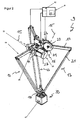
- FIG. 2 Applicator 9 shown in more detail has a punch 33 with which it can receive and transport the labels.
- the applicator is connected at its upper side via a stationary base 11 with the labeling device 1.
- a stationary base 11 with the labeling device 1.
- three articulated arms 13 are each pivotally mounted with their first end about an axis of rotation 15.
- the second ends of the articulated arms 13 are pivotally connected to a support platform 17.
- the carrier platform 17 carries the stamp 33, which serves to receive labels.
- stepper motors 23 are each connected via a gear 25 with an upper portion 19 of the articulated arms 13.
- the stepper motors each pivot the upper portion 19 of the articulated arms 13, whereupon they move accordingly.
- the punch 33 has a cup-shaped housing with a bottom-side perforated plate. Inside the cup-shaped housing, a fan is arranged, which holds with its air flow labels on the bottom plate. On the side of the cup-shaped housing of the punch 33, an acceleration sensor 41 is arranged. About the accelerometer, the acceleration and thus indirectly the way and the speed of the punch 33 are measured.
- the acceleration sensor 41 is connected to a control unit 8, which controls the stepper motors 23.
- the control unit 8 has a microprocessor 81 for calculating the stepper motor drive and three motor output stages 82, which are each connected via cables to one of the stepper motors 23.
- the control unit 8 calculates the energization of the stepping motors 23 associated with a particular labeling operation in accordance with the required speed or acceleration.
- An exemplary driving profile with the associated current profile for different speeds is in the FIG. 3 shown.
- On the ordinate speed v of the applicator or energization i of the stepping motor are shown.
- the time t is shown on the abscissa.
- the speed profile is composed of chronologically consecutive individual travel sections with different speeds v i and accelerations a i .
- the speed shown here encompasses all directions in the xyz coordinate system.
- stepper motors in the prior art are designed for a maximum load or maximum speed and then subjected to a constant voltage or current.
- a relatively high current to the stepper motors is necessary, which increased to an Power consumption and thus can lead to unwanted heating of the stepping motor.
- the respective rated current i i is calculated by multiplying the maximum rated current i max by the quotient of the required speed v i and acceleration a i to maximum speed v max and acceleration a max .
- the quotient will usually be less than 1, since the required speed or acceleration are usually below the maximum speed or acceleration.
- a short time high acceleration can be realized by the quotient is made greater than 1, for example, to achieve a high braking effect.
- the control unit 8 therefore limits the duration of the excessive current i brake to prevent overloading of the stepping motor 23.
- the control unit 8 the duration of the excessive current is set as an adjustable period.
- the controller 8 the period Calculate the time and current yourself from the product, so that the permissible time is shorter when the current i i is high. This short-term overload is made possible by the fact that in the subsequent driving cycles the power consumption is reduced according to the invention and thus the stepping motor can cool down again.
- FIG. 4 a further refinement of the control is shown. It has been shown that in order to maintain the speed of the applicator 9 v i, the operating current i i can be reduced compared to the acceleration phases. This leads to a further refinement of the control with the result that the power consumption and thus the unwanted heating of the stepping motor 23 is further reduced.
Landscapes
- Labeling Devices (AREA)
- Control Of Stepping Motors (AREA)
Description
- Die Erfindung betrifft eine Etikettiervorrichtung gemäß dem Oberbegriff des Anspruchs 1 mit einem über wenigstens einen Schrittmotor angetriebenen Applikator und ein entsprechendes Verfahren, als aus der
WO 97/42086 - Solche Etikettiervorrichtungen sind aus der Praxis bekannt und werden beispielsweise zum automatischen Applizieren von selbstklebenden Etiketten auf Pakete in der Lebensmittel verarbeitenden Industrie oder in der Logistik eingesetzt.
- Ein Verfahren zum Ansteuern eines Schrittmotors ist aus der
DE 199 28 366 C1 bekannt. Dort wird beschrieben, einen Schrittmotor mit Konstantstrom zu beaufschlagen um unerwünschte Resonanzen zu verringen. - In der
DE 43 39 553 C1 ist eine Treiberschaltung für einen Schrittmotor gezeigt, mit der es möglich ist über einen Stromfühlwiderstand den Gesamtstrom einzustellen. - Der Erfindung liegt die Aufgabe zugrunde, eine Etikettiervorrichtung sowie ein Verfahren zum Betrieb einer Etikettiervorrichtung zu schaffen, bei der trotz einer hohen Etikettierleistung der Stromverbrauch möglichst gering gehalten wird.
- Diese Aufgabe wird erfindungsgemäß durch eine Etikettiervorrichtung mit den Merkmalen gemäß dem Anspruch 1, sowie durch ein Verfahren nach den Merkmalen gemäß dem Anspruch 8 gelöst.
- Wenigstens ein einen Applikator zum Applizieren von Etiketten antreibender Schrittmotor der Etikettiervorrichtung wird über ein Steuergerät mit einer festgelegte Stromaufnahme beaufschlagt, wobei der Wert Stromaufnahme aus der erforderlichen Geschwindigkeit und/oder der erforderlichen Beschleunigung des Applikators bestimmt wird.
- Das Steuergerät steuert den wenigstens einen Schrittmotor entsprechend einem geforderten Bewegungsprofil mit entsprechenden Schrittimpulsen an. Die Anzahl der Schrittmotoren kann dabei an die erforderlichen Bewegungsachsen des Applikators angepasst werden. Bei einem eindimensional bewegbaren Applikator genügt ein Schrittmotor. Wenn der Applikator mehrdimensional bewegt werden kann, können dementsprechend mehrere Schrittmotoren angesteuert werden.
- Die Stromaufnahme des Schrittmotors kann gesteuert werden, indem bei konstanter Spannung die Ansteuerung des Schrittmotors durch Pulsweitenmodulation beeinflusst wird, indem das Steuergerät die Breite der einzelnen Pulse entsprechend der Stromaufnahme anpasst. Erfindungsgemäß und die Stromaufnahme gesteuert, indem über eine Strombegrenzung der maximale Strom eines Pulses begrenzt wird. Von Vorteil ist die Strombegrenzung bei einem Schrittmotor vor allem um die Verlustleistung zu begrenzen. Im Gegensatz zu üblichen Elektromotoren, bei denen über die Stromaufnahme auch die Gesschwindigkeit gesteuert wird, wird beim Schrittmotor die Geschwindigkeit über die Ansteuerung bzw. die Schrittfolge gesteuert. Die Begrenzung der Stromaufnahme reduziert bei einem Schrittmotor die Verlustleistung.
- Bei dem Applikator kann es sich um einen linear beweglichen Applikator einer Stempel-Etikettiervorrichtung oder um einen zwei- oder mehrdimensional beweglichen Applikator eines 2D-Etikettierers handeln.
- Die erforderliche Geschwindigkeit oder Beschleunigung bemisst sich insbesondere als Momentangeschwindigkeit oder Momentanbeschleunigung, die sich aus einem erforderlichen Bewegungsprofil des Applikators ergibt. So ein Bewegungsprofil variiert mit dem entsprechenden Etikettiervorgang und hängt neben der absoluten Etikettiergeschwindigkeit von den mechanischen Abmessungen der Etikettiervorrichtung bzw. des zu etikettierenden Paketes ab.
- Je höher die Etikettiergeschwindigkeit ist, desto höher muss die momentane Geschwindigkeit oder Beschleunigung bemessen sein. Eine hohe Geschwindigkeit resultiert in einer hohen Stromaufnahme. Um eine bestimmte maximale Etikettiergeschwindigkeit zu erreichen, muss der Schrittmotor daher mit einer entsprechend hohen Stromaufnahme angesteuert werden. Im Dauerbetrieb führt dies aber zu einem in Summe recht hohen Stromverbrauch, da die maximale Leistung selten abgerufen wird.
- In einer Ausführung ist daher vorgesehen, dass das Steuergerät die erforderliche Geschwindigkeit und/oder die erforderliche Beschleunigung entsprechend dem Verfahrweg des Applikators und der für einen Etikettiervorgang zur Verfügung stehend Zeit bestimmt. Die Zeit wird anhand der vorgegebenen Etikettiergeschwindigkeit bestimmt, indem die Etikettiergeschwindigkeit in Etiketten pro Minute vorgegeben wird und daraus die Zeit pro Etikettiervorgang berechnet wird. Über den Verfahrweg des Applikators kann das Steuergerät dann die erforderliche Geschwindigkeit und/oder die erforderliche Beschleunigung bestimmen.
- Ebenso kann vorgesehen sein, dass das Steuergerät die erforderliche Geschwindigkeit und/oder die erforderliche Beschleunigung über einen Beschleunigungssensor misst. Dadurch erhält man Jederzeit die exakten Werte der Geschwindigkeit und/oder Beschleunigung des Applikators.
- Über den Beschleunigungssensor kann sowohl die Beschleunigung, als auch der Weg und die Geschwindigkeit des Applikators ermittelt werden. Es kann ein Testlauf oder ein Referenzlauf durchgeführt werden. Bei dem Referenzlauf wird ein Paket mit den gewünschten Abmessungen etikettiert, wobei der Weg des Applikators aufgezeichnet wird. Über die Anzahl von Etiketten pro Minute wird die erforderliche Geschwindigkeit eingestellt.
- Von Vorteil ist, wenn bei dem Testlauf ein Geschwindigkeitsprofil, bestehend aus einem Geschwindigkeitsverlauf über die Zeit, aufgenommen und in einem Speicher als Referenz abgelegt wird. Es können mehrere Referenzen bei unterschiedlichen Geschwindigkeiten aufgenommen und abgespeichert werden. Damit erhält man eine Datenbasis, aus der das Steuergerät Zwischenwerte von erforderlichen Geschwindigkeiten durch Approximation einzelner gespeicherter Werte bestimmen kann. Damit können dann unterschiedliche Etikettiervorgänge gesteuert werden, ohne dass jedes Mal zuerst ein Referenzlauf gestartet werden muss.
- Insbesondere kann vorgesehen sein, dass ein Geschwindigkeitsprofil abschnittsweise unterschiedliche Geschwindigkeiten aufweist. Insbesondere kann der Verfahrweg des Applikators mit Etikett bei niedrigerer Geschwindigkeit als der Verfahrweg des Applikators ohne Etikett sein. Oder können senkrecht verlaufende Verfahrwege mit höherer Geschwindigkeit erfolgen als seitliche Verfahrwege. Auch die Größe von Etiketten kann berücksichtigt werden. So können kleinere Etiketten mit größeren Geschwindigkeiten Appliziert werden als größere Etiketten. Ein entsprechendes Geschwindigkeitsprofil wird erstellt, indem vorzugsweise solche Randbedingungen wegeabhängig berücksichtigt werden. Ein Geschwindigkeitsprofil weist demzufolge wenigstens zwei unterschiedliche Geschwindigkeiten auf.
- In einer Ausführung ist vorgesehen, dass das Steuergerät einen Mikroprozessor aufweist, der die Berechnungen durchführt und mehrere Endstufen zum Ansteuern von jeweils einem Schrittmotor aufweist. Dadurch können mit einem Steuergerät mehrere Schrittmotoren angesteuert werden, ohne dass eine aufwändige Datenkommunikation bzw. Synchronisation zwischen verschiedenen Steuergeräten oder Prozessoren stattfinden muss.
- Eine Anwendung der Erfindung ist beispielsweise bei der Etikettierung von Stückgut in der Logistik oder in der Lebensmittel verarbeitenden Industrie vorgesehen.
- Weitere Ausführungsbeispiele der Erfindung sind in den Figuren dargestellt und der dazugehörenden Beschreibung beschrieben.
- Es zeigen,
- Figur 1:
- Eine erfindungsgemäße Etikettiervorrichtung mit einem mehrdimensionalen Applikator;
- Figur 2:
- Eine perspektivische Ansicht des Applikators;
- Figur 3:
- Ein beispielhaftes Diagramm der Stromaufnahme eines Geschwindigkeitsprofils;
- Figur 4:
- Ein Ausschnitt eines Geschwindigkeitsprofils;
- Figur 5:
- Eine Darstellung des Stromverlaufs eines Bremsvorganges.
- In der
Figur 1 ist eine Etikettiervorrichtung 1 dargestellt. Sie dient zum Auszeichnen von Paketen 61, die auf eine Plattform gestellt und dort mit einem Etikett versehen werden. Die Etikettiervorrichtung 1 weist dazu zwei Etikettendrucker 53 und 55 auf, die selbstklebende Etiketten bedrucken und auf einer Spendeeinrichtung 59 bereitstellen. Ein Applikator 9 holt die Etiketten abwechselnd an den Druckern 53 und 55 ab und transportiert das Etikett dann zu dem Paket 61 um es dort auf die Oberfläche zu applizieren. - Der in
Figur 2 näher dargestellte Applikator 9 weist ein Stempel 33 auf, mit dem er die Etiketten aufnehmen und transportieren kann. Der Applikator ist an seiner Oberseite über eine ortsfeste Basis 11 mit der Etikettiervorrichtung 1 verbunden. An der Basis 11 sind drei Gelenkarme 13 mit ihrem ersten Ende jeweils um eine Rotationsachse 15 schwenkbar gelagert. Die zweiten Enden der Gelenkarme 13 sind mit einer Trägerplattform 17 gelenkig verbunden. Die Trägerplattform 17 trägt den Stempel 33, der zur Aufnahme von Etiketten dient. - Drei an der Basis 11 angeordnete Schrittmotoren 23 sind jeweils über ein Getriebe 25 mit einem oberen Abschnitt 19 der Gelenkarme 13 verbunden. Die Schrittmotoren schwenken jeweils den oberen Abschnitt 19 der Gelenkarme 13, worauf diese sich entsprechend bewegen. Durch die Verbindung des zweiten Endes der Gelenkarme 13 über die Trägerplatte 17 ist es möglich, diese bzw. den Stempel 33 dreidimensional,im Raum bzw. im xyz-Koordinatensystem zu bewegen.
- Der Stempel 33 weist ein becherförmiges Gehäuse mit einer bodenseitigen Lochplatte aus. Im Inneren des becherförmigen Gehäuses ist ein Lüfter angeordnet, der mit seinem Luftstrom Etiketten an der Bodenplatte festhält. An der Seite des becherförmigen Gehäuses des Stempels 33 ist ein Beschleunigungssensor 41 angeordnet. Über den Beschleunigungssensor kann die Beschleunigung und damit auch indirekt der Weg und die Geschwindigkeit des Stempels 33 gemessen werden.
- Der Beschleunigungssensor 41 ist mit einem Steuergerät 8 verbunden, welches die Schrittmotoren 23 ansteuert. Dazu weist das Steuergerät 8 einen Mikroprozessor 81 zur Berechnung der Schrittmotoransteuerung und drei Motorendstufen 82 auf, die jeweils über Kabel mit einem der Schrittmotoren 23 verbunden sind.
- Das Steuergerät 8 berechnet die zu einem bestimmten Etikettiervorgang gehörende Bestromung der Schrittmotoren 23 entsprechend der erforderlichen Geschwindigkeit bzw. Beschleunigung. Ein beispielhaftes Fahrprofil mit dem zugehörigen Stromverlauf für verschiedene Geschwindigkeiten ist in der
Figur 3 dargestellt. Auf der Ordinate sind Geschwindigkeit v des Applikators bzw. Bestromung i des Schrittmotors dargestellt. Auf der Abszisse ist der Zeitablauf t dargestellt. Das Geschwindigkeitsprofil setzt sich aus zeitlich aufeinanderfolgenden einzelnen Fahrabschnitten mit jeweils unterschiedlichen Geschwindigkeiten vi und Beschleunigungen ai zusammen. Die dargestellte Geschwindigkeit umfasst dabei alle Richtungen im xyz-Koordinatensystem. - Normalerweise werden Schrittmotoren im Stand der Technik auf eine Maximallast bzw. Maximalgeschwindigkeit hin ausgelegt und dann mit konstanter Spannung bzw. Strom beaufschlagt. Dadurch wird aber eine relativ hohe Bestromung der Schrittmotoren notwendig, die zu einem erhöhten Stromverbrauch und damit zu einer unerwünschten Erwärmung des Schrittmotors führen kann.
- emäß der vorliegenden Erfindung berechnet das Steuergerät 8 die Bestromung nun selektiv anhand der Zielgeschwindigkeit nach der Formel:

- Dabei wird der jeweilige Nennstrom ii berechnet, indem der maximale Nennstrom imax mit dem Quotienten aus erforderlicher Geschwindigkeit vi und Beschleunigung ai zu maximaler Geschwindigkeit vmax und Beschleunigung amax multipliziert wird. Der Quotient wird dabei üblicherweise kleiner als 1 sein, da die erforderlicher Geschwindigkeit bzw. Beschleunigung in der Regel unterhalb der maximalen Geschwindigkeit bzw. Beschleunigung liegen.
- Jedoch kann, wie in
Figur 5 dargestellt, kurzzeitig eine hohe Beschleunigung realisiert werden, indem der Quotient größer 1 gemacht wird um beispielsweise eine hohe Bremswirkung zu erreichen. Dies resultiert in einem hohen erforderlichen Strom ibrems für den Schrittmotor, dessen Stromstärke über der des maximalen Nennstroms des Schrittmotors 23 liegt. Ein solch hoher Strom ist nur zulässig, wenn dieser nur für eine kurze Zeit anliegt. Das Steuergerät 8 begrenzt daher die Zeitdauer des überhöhten Stromes ibrems um eine Überlastung des Schrittmotors 23 zu verhindern. Es ist vorgesehen, dass dem Steuergerät 8 die Zeitdauer des überhöhten Stromes als einstellbare Zeitspanne vorgegeben wird. Zudem kann das Steuergerät 8 die Zeitdauer aus dem Produkt aus Zeit und Strom selbst berechnen, so dass bei hohem Strom ii die zulässige Zeitdauer kürzer wird. Möglich wird diese kurzzeitige Überlastung dadurch, dass in den darauffolgenden Fahrzyklen der Stromverbrauch erfindungsgemäß reduziert wird und so der Schrittmotor wieder abkühlen kann. - In der
Figur 4 ist eine weitere Verfeinerung der Steuerung dargestellt. Es hat sich gezeigt, dass zum Erhalt der Geschwindigkeit des Applikators 9 vi der Betriebsstrom ii gegenüber den Beschleunigungsphasen verringert werden kann. Dies führt zu einer nochmaligen Verfeinerung der Steuerung mit dem Ergebnis, dass der Stromverbrauch und damit die unerwünschte Erwärmung des Schrittmotors 23 weiter reduziert wird.
Claims (11)
- Etikettiervorrichtung (1) mit einem über wenigstens einen Schrittmotor (23) angetriebenen Applikator (9) zum Applizieren von Etiketten und einem Steuergerät (8) zum Ansteuern des Applikators (9), wobei das Steuergerät (8) den Betriebsstrom des Schrittmotors (23) bestimmt, wobei
das Steuergerät (8) den Betriebsstrom des Schrittmotors (23) entsprechend der erforderlichen Geschwindigkeit und/oder der erforderlichen Beschleunigung des Applikators (9) festlegt, dadurch gekennzeichnet, dass das Steuergerät die Stromaufnahme des Schrittmotors (23) steuert, indem es bei konstanter Spannung über eine Strombegrenzung den maximalen Strom eines Pulses begrenzt, und dass das Steuergerät (8) den Betriebsstrom berechnet, indem der maximale Nennstrom des Schrittmotors (23) mit dem Quotient aus momentaner Geschwindigkeit zu maximaler Geschwindigkeit und/oder mit dem Quotient aus momentaner Beschleunigung zu maximaler Beschleunigung multipliziert wird. - Etikettiervorrichtung nach Anspruch 1,
dadurch gekennzeichnet,
dass das Steuergerät (8) die erforderliche Geschwindigkeit und/oder die erforderliche Beschleunigung entsprechend dem Verfahrweg des Applikators (9) und der für einen Etikettiervorgang zur Verfügung stehenden Zeit bestimmt. - Etikettiervorrichtung nach Anspruch 1,
dadurch gekennzeichnet,
dass das Steuergerät (8) die erforderliche Geschwindigkeit und/oder die erforderliche Beschleunigung über einen an dem Applikator (9) angebrachten Beschleunigungssensor (41) während des Betriebs oder während eines Testlaufs bestimmt. - Etikettiervorrichtung nach Anspruch 2 oder 3,
dadurch gekennzeichnet,
dass das Geschwindigkeitsprofil wenigstens zwei unterschiedliche Geschwindigkeiten des Applikators (9) aufweist. - Etikettiervorrichtung nach einem der Ansprüche 1 bis 4,
dadurch gekennzeichnet,
dass das Steuergerät (8) einen Speicher aufweist, der zum Speichern verschiedener Geschwindigkeitsprofile, vorzugsweise verschiedener Geschwindigkeitswerte und/oder Beschleunigungswerte bei jeweils unterschiedlichen Etikettiervorgängen und/oder Etikettiergeschwindigkeiten ausgebildet ist. - Etikettiervorrichtung nach Anspruch 5,
dadurch gekennzeichnet,
dass der Quotient aus momentaner Geschwindigkeit zu maximaler Geschwindigkeit und/oder der Quotient aus momentaner Beschleunigung zu maximaler Beschleunigung grösser als eins sein kann, wobei das Steuergerät (8) das Produkt aus Betriebsstrom und Zeit auf einen vorzugsweise einstellbaren Maximalwert begrenzt. - Etikettiervorrichtung nach einem der vorhergehenden Ansprüche,
dadurch gekennzeichnet,
dass das Steuergerät (8) mehrere Schrittmotoren (23) ansteuert, wobei das Steuergerät (8) einen Mikroprozessor zur Bestimmung des Betriebsstromes und mehrere Motorendstufen zur Ansteuerung jeweils eines Schrittmotors (23) aufweist. - Verfahren zum Ansteuern eines Schrittmotors (23) einer Etikettiervorrichtung (1), wobei die Stromaufnahme des Schrittmotors (23) entsprechend der erforderlichen Geschwindigkeit und/oder der erforderlichen Beschleunigung eines von dem Schrittmotor (23) bewegten Applikators (9) festgelegt wird, indem bei konstanter Spannung über eine Strombegrenzung der maximale Strom eines Pulses begrenzt wird, wobei ein Nennstrom berechnet wird, indem der maximale Nennstrom mit dem Quotienten aus erforderlicher Geschwindigkeit und Beschleunigung zu maximaler Geschwindigkeit und maximaler Beschleunigung multipliziert wird..
- Verfahren nach Anspruch 8,
dadurch gekennzeichnet,
dass die erforderliche Geschwindigkeit und/oder die erforderliche Beschleunigung anhand einer gewünschten Etikettiergeschwindigkeit und einem Bewegungsprofil des Applikators (9) bestimmt wird. - Verfahren nach Anspruch 8 oder 9,
dadurch gekennzeichnet,
dass das Bewegungsprofil anhand eines Referenzlaufs des Applikators (9) erstellt und in einem Speicher abgespeichert wird. - Verfahren nach einem der Ansprüche 8 bis 10,
dadurch gekennzeichnet,
dass dem Bewegungsprofil bei einer senkrecht verlaufenden Bewegung des Applikators (9) eine andere Geschwindigkeit zugeordnet wird als bei einer horizontal verlaufenden Bewegung.
Applications Claiming Priority (2)
| Application Number | Priority Date | Filing Date | Title |
|---|---|---|---|
| DE102010055157A DE102010055157A1 (de) | 2010-12-18 | 2010-12-18 | Etikettiervorrichtung |
| PCT/EP2011/006182 WO2012079725A1 (de) | 2010-12-18 | 2011-12-08 | Etikettiervorrichtung |
Publications (2)
| Publication Number | Publication Date |
|---|---|
| EP2651769A1 EP2651769A1 (de) | 2013-10-23 |
| EP2651769B1 true EP2651769B1 (de) | 2015-08-19 |
Family
ID=45418602
Family Applications (1)
| Application Number | Title | Priority Date | Filing Date |
|---|---|---|---|
| EP11801976.9A Active EP2651769B1 (de) | 2010-12-18 | 2011-12-08 | Etikettiervorrichtung |
Country Status (3)
| Country | Link |
|---|---|
| EP (1) | EP2651769B1 (de) |
| DE (1) | DE102010055157A1 (de) |
| WO (1) | WO2012079725A1 (de) |
Cited By (1)
| Publication number | Priority date | Publication date | Assignee | Title |
|---|---|---|---|---|
| EP4005742A1 (de) | 2020-11-27 | 2022-06-01 | Bizerba SE & Co. KG | Etikettenapplikator |
Families Citing this family (4)
| Publication number | Priority date | Publication date | Assignee | Title |
|---|---|---|---|---|
| CN103607147A (zh) * | 2013-10-17 | 2014-02-26 | 苏建中 | 一种自动盖章机的压力控制装置 |
| EP3152034B1 (de) | 2014-06-09 | 2024-07-17 | Hybrid Manufacturing Technologies Limited | Materialbearbeitungsverfahren und zugehörige vorrichtung |
| GB2581123B (en) | 2018-11-30 | 2023-08-02 | Dover Europe Sarl | Applicator apparatus and method |
| EP3854706A1 (de) | 2020-01-27 | 2021-07-28 | Dover Europe Sàrl | Etikettenapplikationssystem |
Family Cites Families (14)
| Publication number | Priority date | Publication date | Assignee | Title |
|---|---|---|---|---|
| SE439145B (sv) * | 1979-10-01 | 1985-06-03 | Toennesen Ulf | Forfaringssett och anordning for att repetitivt astadkomma ett kontakttryck av forutbestemd storlek |
| GB9002646D0 (en) * | 1990-02-06 | 1990-04-04 | Harland Mach Syst | A control system for labelling apparatus |
| US5232539A (en) * | 1991-02-22 | 1993-08-03 | Grand Rapids Label Company | Object labeling machine |
| DE4339553C1 (de) | 1993-11-19 | 1995-06-22 | Sgs Thomson Microelectronics | Treiberschaltung für einen Schrittmotor |
| GB9609379D0 (en) * | 1996-05-03 | 1996-07-10 | Willett Int Ltd | Mechanism and method |
| US6230779B1 (en) * | 1998-03-23 | 2001-05-15 | Fmc Corporation | Labeling apparatus with enhanced bellows and associated method |
| GB9808415D0 (en) * | 1998-04-22 | 1998-06-17 | Snape Neil | Transfer apparatus |
| DE19928366C1 (de) | 1999-06-21 | 2001-01-25 | Sig Positec Bergerlahr Gmbh & | Verfahren zum Betreiben eines Antriebssystems mit einem Schrittmotor |
| US6563280B2 (en) * | 2000-03-06 | 2003-05-13 | Whedco, Inc. | Pulse based servo motor controlled labeler |
| US6550517B1 (en) * | 2000-03-07 | 2003-04-22 | Kimberly-Clark Worldwide, Inc. | Apparatus for transferring a discrete portion of a first web onto a second web |
| DE10253843B3 (de) * | 2002-11-14 | 2004-05-06 | Bizerba Gmbh & Co. Kg | Etikettiervorrichtung für bewegte Gegenstände und Verfahren zur Etikettierung von bewegten Gegenständen |
| US7886795B2 (en) * | 2006-03-09 | 2011-02-15 | Illinois Tool Works Inc. | High speed decorating system |
| DE102006043537B4 (de) * | 2006-09-12 | 2016-09-29 | 3Py GmbH & Co. KG | Applikator für Etikettiermaschine und Verfahren zum Etikettieren |
| DE102009041470A1 (de) * | 2009-09-14 | 2011-03-24 | Bizerba Gmbh & Co Kg | Roboter mit Delta-Kinematik |
-
2010
- 2010-12-18 DE DE102010055157A patent/DE102010055157A1/de not_active Withdrawn
-
2011
- 2011-12-08 EP EP11801976.9A patent/EP2651769B1/de active Active
- 2011-12-08 WO PCT/EP2011/006182 patent/WO2012079725A1/de not_active Ceased
Cited By (5)
| Publication number | Priority date | Publication date | Assignee | Title |
|---|---|---|---|---|
| EP4005742A1 (de) | 2020-11-27 | 2022-06-01 | Bizerba SE & Co. KG | Etikettenapplikator |
| US11535414B2 (en) | 2020-11-27 | 2022-12-27 | Bizerba SE & Co. KG | Label applicator |
| US11760527B2 (en) | 2020-11-27 | 2023-09-19 | Bizerba SE & Co. KG | Label applicator |
| US11760526B2 (en) | 2020-11-27 | 2023-09-19 | Bizerba SE & Co. KG | Label applicator |
| US11794937B2 (en) | 2020-11-27 | 2023-10-24 | Bizerba SE & Co. KG | Label applicator |
Also Published As
| Publication number | Publication date |
|---|---|
| WO2012079725A1 (de) | 2012-06-21 |
| DE102010055157A1 (de) | 2012-06-21 |
| EP2651769A1 (de) | 2013-10-23 |
Similar Documents
| Publication | Publication Date | Title |
|---|---|---|
| EP2651769B1 (de) | Etikettiervorrichtung | |
| EP2666728B1 (de) | Etikettierer und Verfahren zum Etikettieren | |
| AT516875B1 (de) | Verfahren zum Einlagern von Stückgütern in ein Lagerregal und Lagersystem | |
| EP0850709B1 (de) | Transfereinrichtung und Mehrstationenpresse | |
| DE19548533C2 (de) | Verfahren zur Überwachung der Qualität von Crimpverbindungen | |
| EP2113482B1 (de) | Hebevorrichtung | |
| DE2912164A1 (de) | Transporteinrichtung fuer serviertablette u.dgl. | |
| WO2001030488A2 (de) | Misvorrichtung und -verfahren | |
| DE3339924A1 (de) | Verpackungsmaschine | |
| DE19548534A1 (de) | Vorrichtung zum Zusammenquetschen von Kontaktelement und Elektrodraht | |
| EP1902792A2 (de) | Verfahren zum Betrieb einer Biegepresse, insbesondere Abkantpresse | |
| EP3095533A1 (de) | Verfahren und anlage für das richten von metallischen teilen | |
| DE19721272B4 (de) | Elektrische Preßvorrichtung | |
| CH708823B1 (de) | Vorrichtung und Verfahren zum Wenden von Werkstücken. | |
| EP2772445B1 (de) | Verstellportal, Schrumpfvorrichtung mit einstellbaren Schachtwänden und Verfahren zur Einstellung von Schachtwänden | |
| DE19925343A1 (de) | Transfereinrichtung | |
| DE102010060308A1 (de) | Vorrichtung und Verfahren zur Mehrfachabfüllung hochviskoser Materialien | |
| EP3877140B1 (de) | Verfahren und vorrichtung für die kontrolle eines dickenprofils einer folienbahn | |
| EP1769572A1 (de) | Fahrzeug zum einlegen wenigstens einer elektrischen leitung in die nuten eines langstators | |
| EP2379411B1 (de) | Vorrichtung zum abfüllen und verdichten rieselfähiger produkte | |
| EP4454475B1 (de) | Vorrichtung zum ausgeben von erwärmter süsswarenmasse auf ein förderband oder auf darauf geförderte objekte | |
| DE2707624A1 (de) | Leitervorschubeinrichtung | |
| EP1872098A1 (de) | Verpackungsmaschine | |
| DE2751605A1 (de) | Verfahren und vorrichtung zum stapeln von brettern o.dgl. | |
| EP3295800A1 (de) | Sandwichkeksvorrichtung |
Legal Events
| Date | Code | Title | Description |
|---|---|---|---|
| PUAI | Public reference made under article 153(3) epc to a published international application that has entered the european phase |
Free format text: ORIGINAL CODE: 0009012 |
|
| 17P | Request for examination filed |
Effective date: 20130704 |
|
| AK | Designated contracting states |
Kind code of ref document: A1 Designated state(s): AL AT BE BG CH CY CZ DE DK EE ES FI FR GB GR HR HU IE IS IT LI LT LU LV MC MK MT NL NO PL PT RO RS SE SI SK SM TR |
|
| DAX | Request for extension of the european patent (deleted) | ||
| 17Q | First examination report despatched |
Effective date: 20140721 |
|
| GRAP | Despatch of communication of intention to grant a patent |
Free format text: ORIGINAL CODE: EPIDOSNIGR1 |
|
| INTG | Intention to grant announced |
Effective date: 20150417 |
|
| GRAS | Grant fee paid |
Free format text: ORIGINAL CODE: EPIDOSNIGR3 |
|
| GRAA | (expected) grant |
Free format text: ORIGINAL CODE: 0009210 |
|
| AK | Designated contracting states |
Kind code of ref document: B1 Designated state(s): AL AT BE BG CH CY CZ DE DK EE ES FI FR GB GR HR HU IE IS IT LI LT LU LV MC MK MT NL NO PL PT RO RS SE SI SK SM TR |
|
| REG | Reference to a national code |
Ref country code: GB Ref legal event code: FG4D Free format text: NOT ENGLISH |
|
| REG | Reference to a national code |
Ref country code: CH Ref legal event code: EP |
|
| REG | Reference to a national code |
Ref country code: IE Ref legal event code: FG4D Free format text: LANGUAGE OF EP DOCUMENT: GERMAN |
|
| REG | Reference to a national code |
Ref country code: AT Ref legal event code: REF Ref document number: 743606 Country of ref document: AT Kind code of ref document: T Effective date: 20150915 |
|
| REG | Reference to a national code |
Ref country code: DE Ref legal event code: R096 Ref document number: 502011007657 Country of ref document: DE |
|
| REG | Reference to a national code |
Ref country code: FR Ref legal event code: PLFP Year of fee payment: 5 |
|
| REG | Reference to a national code |
Ref country code: LT Ref legal event code: MG4D |
|
| REG | Reference to a national code |
Ref country code: NL Ref legal event code: MP Effective date: 20150819 |
|
| PG25 | Lapsed in a contracting state [announced via postgrant information from national office to epo] |
Ref country code: FI Free format text: LAPSE BECAUSE OF FAILURE TO SUBMIT A TRANSLATION OF THE DESCRIPTION OR TO PAY THE FEE WITHIN THE PRESCRIBED TIME-LIMIT Effective date: 20150819 Ref country code: LT Free format text: LAPSE BECAUSE OF FAILURE TO SUBMIT A TRANSLATION OF THE DESCRIPTION OR TO PAY THE FEE WITHIN THE PRESCRIBED TIME-LIMIT Effective date: 20150819 Ref country code: NO Free format text: LAPSE BECAUSE OF FAILURE TO SUBMIT A TRANSLATION OF THE DESCRIPTION OR TO PAY THE FEE WITHIN THE PRESCRIBED TIME-LIMIT Effective date: 20151119 Ref country code: LV Free format text: LAPSE BECAUSE OF FAILURE TO SUBMIT A TRANSLATION OF THE DESCRIPTION OR TO PAY THE FEE WITHIN THE PRESCRIBED TIME-LIMIT Effective date: 20150819 Ref country code: GR Free format text: LAPSE BECAUSE OF FAILURE TO SUBMIT A TRANSLATION OF THE DESCRIPTION OR TO PAY THE FEE WITHIN THE PRESCRIBED TIME-LIMIT Effective date: 20151120 |
|
| PG25 | Lapsed in a contracting state [announced via postgrant information from national office to epo] |
Ref country code: PT Free format text: LAPSE BECAUSE OF FAILURE TO SUBMIT A TRANSLATION OF THE DESCRIPTION OR TO PAY THE FEE WITHIN THE PRESCRIBED TIME-LIMIT Effective date: 20151221 Ref country code: IS Free format text: LAPSE BECAUSE OF FAILURE TO SUBMIT A TRANSLATION OF THE DESCRIPTION OR TO PAY THE FEE WITHIN THE PRESCRIBED TIME-LIMIT Effective date: 20151219 Ref country code: RS Free format text: LAPSE BECAUSE OF FAILURE TO SUBMIT A TRANSLATION OF THE DESCRIPTION OR TO PAY THE FEE WITHIN THE PRESCRIBED TIME-LIMIT Effective date: 20150819 Ref country code: ES Free format text: LAPSE BECAUSE OF FAILURE TO SUBMIT A TRANSLATION OF THE DESCRIPTION OR TO PAY THE FEE WITHIN THE PRESCRIBED TIME-LIMIT Effective date: 20150819 Ref country code: SE Free format text: LAPSE BECAUSE OF FAILURE TO SUBMIT A TRANSLATION OF THE DESCRIPTION OR TO PAY THE FEE WITHIN THE PRESCRIBED TIME-LIMIT Effective date: 20150819 Ref country code: PL Free format text: LAPSE BECAUSE OF FAILURE TO SUBMIT A TRANSLATION OF THE DESCRIPTION OR TO PAY THE FEE WITHIN THE PRESCRIBED TIME-LIMIT Effective date: 20150819 |
|
| PG25 | Lapsed in a contracting state [announced via postgrant information from national office to epo] |
Ref country code: NL Free format text: LAPSE BECAUSE OF FAILURE TO SUBMIT A TRANSLATION OF THE DESCRIPTION OR TO PAY THE FEE WITHIN THE PRESCRIBED TIME-LIMIT Effective date: 20150819 |
|
| PG25 | Lapsed in a contracting state [announced via postgrant information from national office to epo] |
Ref country code: CZ Free format text: LAPSE BECAUSE OF FAILURE TO SUBMIT A TRANSLATION OF THE DESCRIPTION OR TO PAY THE FEE WITHIN THE PRESCRIBED TIME-LIMIT Effective date: 20150819 Ref country code: EE Free format text: LAPSE BECAUSE OF FAILURE TO SUBMIT A TRANSLATION OF THE DESCRIPTION OR TO PAY THE FEE WITHIN THE PRESCRIBED TIME-LIMIT Effective date: 20150819 Ref country code: SK Free format text: LAPSE BECAUSE OF FAILURE TO SUBMIT A TRANSLATION OF THE DESCRIPTION OR TO PAY THE FEE WITHIN THE PRESCRIBED TIME-LIMIT Effective date: 20150819 Ref country code: DK Free format text: LAPSE BECAUSE OF FAILURE TO SUBMIT A TRANSLATION OF THE DESCRIPTION OR TO PAY THE FEE WITHIN THE PRESCRIBED TIME-LIMIT Effective date: 20150819 |
|
| REG | Reference to a national code |
Ref country code: DE Ref legal event code: R097 Ref document number: 502011007657 Country of ref document: DE |
|
| PG25 | Lapsed in a contracting state [announced via postgrant information from national office to epo] |
Ref country code: BE Free format text: LAPSE BECAUSE OF NON-PAYMENT OF DUE FEES Effective date: 20151231 Ref country code: RO Free format text: LAPSE BECAUSE OF FAILURE TO SUBMIT A TRANSLATION OF THE DESCRIPTION OR TO PAY THE FEE WITHIN THE PRESCRIBED TIME-LIMIT Effective date: 20150819 |
|
| PLBE | No opposition filed within time limit |
Free format text: ORIGINAL CODE: 0009261 |
|
| STAA | Information on the status of an ep patent application or granted ep patent |
Free format text: STATUS: NO OPPOSITION FILED WITHIN TIME LIMIT |
|
| 26N | No opposition filed |
Effective date: 20160520 |
|
| PG25 | Lapsed in a contracting state [announced via postgrant information from national office to epo] |
Ref country code: LU Free format text: LAPSE BECAUSE OF FAILURE TO SUBMIT A TRANSLATION OF THE DESCRIPTION OR TO PAY THE FEE WITHIN THE PRESCRIBED TIME-LIMIT Effective date: 20151208 Ref country code: MC Free format text: LAPSE BECAUSE OF FAILURE TO SUBMIT A TRANSLATION OF THE DESCRIPTION OR TO PAY THE FEE WITHIN THE PRESCRIBED TIME-LIMIT Effective date: 20150819 |
|
| REG | Reference to a national code |
Ref country code: CH Ref legal event code: PL |
|
| PG25 | Lapsed in a contracting state [announced via postgrant information from national office to epo] |
Ref country code: SI Free format text: LAPSE BECAUSE OF FAILURE TO SUBMIT A TRANSLATION OF THE DESCRIPTION OR TO PAY THE FEE WITHIN THE PRESCRIBED TIME-LIMIT Effective date: 20150819 |
|
| REG | Reference to a national code |
Ref country code: IE Ref legal event code: MM4A |
|
| PG25 | Lapsed in a contracting state [announced via postgrant information from national office to epo] |
Ref country code: CH Free format text: LAPSE BECAUSE OF NON-PAYMENT OF DUE FEES Effective date: 20151231 Ref country code: IE Free format text: LAPSE BECAUSE OF NON-PAYMENT OF DUE FEES Effective date: 20151208 Ref country code: LI Free format text: LAPSE BECAUSE OF NON-PAYMENT OF DUE FEES Effective date: 20151231 |
|
| REG | Reference to a national code |
Ref country code: FR Ref legal event code: PLFP Year of fee payment: 6 |
|
| REG | Reference to a national code |
Ref country code: DE Ref legal event code: R082 Ref document number: 502011007657 Country of ref document: DE Representative=s name: KANZLEI LOUIS POEHLAU LOHRENTZ, DE Ref country code: DE Ref legal event code: R081 Ref document number: 502011007657 Country of ref document: DE Owner name: BIZERBA SE & CO. KG, DE Free format text: FORMER OWNER: BIZERBA GMBH & CO KG, 72336 BALINGEN, DE |
|
| PG25 | Lapsed in a contracting state [announced via postgrant information from national office to epo] |
Ref country code: HU Free format text: LAPSE BECAUSE OF FAILURE TO SUBMIT A TRANSLATION OF THE DESCRIPTION OR TO PAY THE FEE WITHIN THE PRESCRIBED TIME-LIMIT; INVALID AB INITIO Effective date: 20111208 Ref country code: BG Free format text: LAPSE BECAUSE OF FAILURE TO SUBMIT A TRANSLATION OF THE DESCRIPTION OR TO PAY THE FEE WITHIN THE PRESCRIBED TIME-LIMIT Effective date: 20150819 Ref country code: SM Free format text: LAPSE BECAUSE OF FAILURE TO SUBMIT A TRANSLATION OF THE DESCRIPTION OR TO PAY THE FEE WITHIN THE PRESCRIBED TIME-LIMIT Effective date: 20150819 |
|
| PG25 | Lapsed in a contracting state [announced via postgrant information from national office to epo] |
Ref country code: CY Free format text: LAPSE BECAUSE OF FAILURE TO SUBMIT A TRANSLATION OF THE DESCRIPTION OR TO PAY THE FEE WITHIN THE PRESCRIBED TIME-LIMIT Effective date: 20150819 |
|
| PG25 | Lapsed in a contracting state [announced via postgrant information from national office to epo] |
Ref country code: HR Free format text: LAPSE BECAUSE OF FAILURE TO SUBMIT A TRANSLATION OF THE DESCRIPTION OR TO PAY THE FEE WITHIN THE PRESCRIBED TIME-LIMIT Effective date: 20150819 |
|
| PG25 | Lapsed in a contracting state [announced via postgrant information from national office to epo] |
Ref country code: MT Free format text: LAPSE BECAUSE OF FAILURE TO SUBMIT A TRANSLATION OF THE DESCRIPTION OR TO PAY THE FEE WITHIN THE PRESCRIBED TIME-LIMIT Effective date: 20150819 |
|
| REG | Reference to a national code |
Ref country code: FR Ref legal event code: PLFP Year of fee payment: 7 |
|
| REG | Reference to a national code |
Ref country code: AT Ref legal event code: MM01 Ref document number: 743606 Country of ref document: AT Kind code of ref document: T Effective date: 20161208 |
|
| PG25 | Lapsed in a contracting state [announced via postgrant information from national office to epo] |
Ref country code: AT Free format text: LAPSE BECAUSE OF NON-PAYMENT OF DUE FEES Effective date: 20161208 |
|
| PG25 | Lapsed in a contracting state [announced via postgrant information from national office to epo] |
Ref country code: MK Free format text: LAPSE BECAUSE OF FAILURE TO SUBMIT A TRANSLATION OF THE DESCRIPTION OR TO PAY THE FEE WITHIN THE PRESCRIBED TIME-LIMIT Effective date: 20150819 Ref country code: TR Free format text: LAPSE BECAUSE OF FAILURE TO SUBMIT A TRANSLATION OF THE DESCRIPTION OR TO PAY THE FEE WITHIN THE PRESCRIBED TIME-LIMIT Effective date: 20150819 |
|
| PG25 | Lapsed in a contracting state [announced via postgrant information from national office to epo] |
Ref country code: AL Free format text: LAPSE BECAUSE OF FAILURE TO SUBMIT A TRANSLATION OF THE DESCRIPTION OR TO PAY THE FEE WITHIN THE PRESCRIBED TIME-LIMIT Effective date: 20150819 |
|
| PGFP | Annual fee paid to national office [announced via postgrant information from national office to epo] |
Ref country code: GB Payment date: 20251218 Year of fee payment: 15 |
|
| PGFP | Annual fee paid to national office [announced via postgrant information from national office to epo] |
Ref country code: FR Payment date: 20251218 Year of fee payment: 15 |
|
| PGFP | Annual fee paid to national office [announced via postgrant information from national office to epo] |
Ref country code: DE Payment date: 20251222 Year of fee payment: 15 |
|
| PGFP | Annual fee paid to national office [announced via postgrant information from national office to epo] |
Ref country code: IT Payment date: 20251231 Year of fee payment: 15 |