EP2651008A1 - Wireless power-transfer equipment and method for controlling vehicle and wireless power-transfer system - Google Patents
Wireless power-transfer equipment and method for controlling vehicle and wireless power-transfer system Download PDFInfo
- Publication number
- EP2651008A1 EP2651008A1 EP10859617.2A EP10859617A EP2651008A1 EP 2651008 A1 EP2651008 A1 EP 2651008A1 EP 10859617 A EP10859617 A EP 10859617A EP 2651008 A1 EP2651008 A1 EP 2651008A1
- Authority
- EP
- European Patent Office
- Prior art keywords
- power
- receiving
- impedance
- feeding apparatus
- mismatch amount
- Prior art date
- Legal status (The legal status is an assumption and is not a legal conclusion. Google has not performed a legal analysis and makes no representation as to the accuracy of the status listed.)
- Granted
Links
Images


Classifications
-
- B—PERFORMING OPERATIONS; TRANSPORTING
- B60—VEHICLES IN GENERAL
- B60L—PROPULSION OF ELECTRICALLY-PROPELLED VEHICLES; SUPPLYING ELECTRIC POWER FOR AUXILIARY EQUIPMENT OF ELECTRICALLY-PROPELLED VEHICLES; ELECTRODYNAMIC BRAKE SYSTEMS FOR VEHICLES IN GENERAL; MAGNETIC SUSPENSION OR LEVITATION FOR VEHICLES; MONITORING OPERATING VARIABLES OF ELECTRICALLY-PROPELLED VEHICLES; ELECTRIC SAFETY DEVICES FOR ELECTRICALLY-PROPELLED VEHICLES
- B60L53/00—Methods of charging batteries, specially adapted for electric vehicles; Charging stations or on-board charging equipment therefor; Exchange of energy storage elements in electric vehicles
- B60L53/10—Methods of charging batteries, specially adapted for electric vehicles; Charging stations or on-board charging equipment therefor; Exchange of energy storage elements in electric vehicles characterised by the energy transfer between the charging station and the vehicle
- B60L53/12—Inductive energy transfer
-
- B—PERFORMING OPERATIONS; TRANSPORTING
- B60—VEHICLES IN GENERAL
- B60L—PROPULSION OF ELECTRICALLY-PROPELLED VEHICLES; SUPPLYING ELECTRIC POWER FOR AUXILIARY EQUIPMENT OF ELECTRICALLY-PROPELLED VEHICLES; ELECTRODYNAMIC BRAKE SYSTEMS FOR VEHICLES IN GENERAL; MAGNETIC SUSPENSION OR LEVITATION FOR VEHICLES; MONITORING OPERATING VARIABLES OF ELECTRICALLY-PROPELLED VEHICLES; ELECTRIC SAFETY DEVICES FOR ELECTRICALLY-PROPELLED VEHICLES
- B60L50/00—Electric propulsion with power supplied within the vehicle
- B60L50/50—Electric propulsion with power supplied within the vehicle using propulsion power supplied by batteries or fuel cells
- B60L50/60—Electric propulsion with power supplied within the vehicle using propulsion power supplied by batteries or fuel cells using power supplied by batteries
- B60L50/61—Electric propulsion with power supplied within the vehicle using propulsion power supplied by batteries or fuel cells using power supplied by batteries by batteries charged by engine-driven generators, e.g. series hybrid electric vehicles
- B60L50/62—Electric propulsion with power supplied within the vehicle using propulsion power supplied by batteries or fuel cells using power supplied by batteries by batteries charged by engine-driven generators, e.g. series hybrid electric vehicles charged by low-power generators primarily intended to support the batteries, e.g. range extenders
-
- B—PERFORMING OPERATIONS; TRANSPORTING
- B60—VEHICLES IN GENERAL
- B60L—PROPULSION OF ELECTRICALLY-PROPELLED VEHICLES; SUPPLYING ELECTRIC POWER FOR AUXILIARY EQUIPMENT OF ELECTRICALLY-PROPELLED VEHICLES; ELECTRODYNAMIC BRAKE SYSTEMS FOR VEHICLES IN GENERAL; MAGNETIC SUSPENSION OR LEVITATION FOR VEHICLES; MONITORING OPERATING VARIABLES OF ELECTRICALLY-PROPELLED VEHICLES; ELECTRIC SAFETY DEVICES FOR ELECTRICALLY-PROPELLED VEHICLES
- B60L53/00—Methods of charging batteries, specially adapted for electric vehicles; Charging stations or on-board charging equipment therefor; Exchange of energy storage elements in electric vehicles
- B60L53/10—Methods of charging batteries, specially adapted for electric vehicles; Charging stations or on-board charging equipment therefor; Exchange of energy storage elements in electric vehicles characterised by the energy transfer between the charging station and the vehicle
- B60L53/12—Inductive energy transfer
- B60L53/126—Methods for pairing a vehicle and a charging station, e.g. establishing a one-to-one relation between a wireless power transmitter and a wireless power receiver
-
- B—PERFORMING OPERATIONS; TRANSPORTING
- B60—VEHICLES IN GENERAL
- B60L—PROPULSION OF ELECTRICALLY-PROPELLED VEHICLES; SUPPLYING ELECTRIC POWER FOR AUXILIARY EQUIPMENT OF ELECTRICALLY-PROPELLED VEHICLES; ELECTRODYNAMIC BRAKE SYSTEMS FOR VEHICLES IN GENERAL; MAGNETIC SUSPENSION OR LEVITATION FOR VEHICLES; MONITORING OPERATING VARIABLES OF ELECTRICALLY-PROPELLED VEHICLES; ELECTRIC SAFETY DEVICES FOR ELECTRICALLY-PROPELLED VEHICLES
- B60L53/00—Methods of charging batteries, specially adapted for electric vehicles; Charging stations or on-board charging equipment therefor; Exchange of energy storage elements in electric vehicles
- B60L53/30—Constructional details of charging stations
- B60L53/35—Means for automatic or assisted adjustment of the relative position of charging devices and vehicles
- B60L53/36—Means for automatic or assisted adjustment of the relative position of charging devices and vehicles by positioning the vehicle
-
- B—PERFORMING OPERATIONS; TRANSPORTING
- B60—VEHICLES IN GENERAL
- B60L—PROPULSION OF ELECTRICALLY-PROPELLED VEHICLES; SUPPLYING ELECTRIC POWER FOR AUXILIARY EQUIPMENT OF ELECTRICALLY-PROPELLED VEHICLES; ELECTRODYNAMIC BRAKE SYSTEMS FOR VEHICLES IN GENERAL; MAGNETIC SUSPENSION OR LEVITATION FOR VEHICLES; MONITORING OPERATING VARIABLES OF ELECTRICALLY-PROPELLED VEHICLES; ELECTRIC SAFETY DEVICES FOR ELECTRICALLY-PROPELLED VEHICLES
- B60L58/00—Methods or circuit arrangements for monitoring or controlling batteries or fuel cells, specially adapted for electric vehicles
- B60L58/10—Methods or circuit arrangements for monitoring or controlling batteries or fuel cells, specially adapted for electric vehicles for monitoring or controlling batteries
- B60L58/12—Methods or circuit arrangements for monitoring or controlling batteries or fuel cells, specially adapted for electric vehicles for monitoring or controlling batteries responding to state of charge [SoC]
-
- H—ELECTRICITY
- H01—ELECTRIC ELEMENTS
- H01F—MAGNETS; INDUCTANCES; TRANSFORMERS; SELECTION OF MATERIALS FOR THEIR MAGNETIC PROPERTIES
- H01F38/00—Adaptations of transformers or inductances for specific applications or functions
- H01F38/14—Inductive couplings
-
- H—ELECTRICITY
- H02—GENERATION; CONVERSION OR DISTRIBUTION OF ELECTRIC POWER
- H02J—CIRCUIT ARRANGEMENTS OR SYSTEMS FOR SUPPLYING OR DISTRIBUTING ELECTRIC POWER; SYSTEMS FOR STORING ELECTRIC ENERGY
- H02J50/00—Circuit arrangements or systems for wireless supply or distribution of electric power
- H02J50/10—Circuit arrangements or systems for wireless supply or distribution of electric power using inductive coupling
- H02J50/12—Circuit arrangements or systems for wireless supply or distribution of electric power using inductive coupling of the resonant type
-
- H—ELECTRICITY
- H02—GENERATION; CONVERSION OR DISTRIBUTION OF ELECTRIC POWER
- H02J—CIRCUIT ARRANGEMENTS OR SYSTEMS FOR SUPPLYING OR DISTRIBUTING ELECTRIC POWER; SYSTEMS FOR STORING ELECTRIC ENERGY
- H02J50/00—Circuit arrangements or systems for wireless supply or distribution of electric power
- H02J50/80—Circuit arrangements or systems for wireless supply or distribution of electric power involving the exchange of data, concerning supply or distribution of electric power, between transmitting devices and receiving devices
-
- H—ELECTRICITY
- H02—GENERATION; CONVERSION OR DISTRIBUTION OF ELECTRIC POWER
- H02J—CIRCUIT ARRANGEMENTS OR SYSTEMS FOR SUPPLYING OR DISTRIBUTING ELECTRIC POWER; SYSTEMS FOR STORING ELECTRIC ENERGY
- H02J50/00—Circuit arrangements or systems for wireless supply or distribution of electric power
- H02J50/90—Circuit arrangements or systems for wireless supply or distribution of electric power involving detection or optimisation of position, e.g. alignment
-
- H—ELECTRICITY
- H02—GENERATION; CONVERSION OR DISTRIBUTION OF ELECTRIC POWER
- H02J—CIRCUIT ARRANGEMENTS OR SYSTEMS FOR SUPPLYING OR DISTRIBUTING ELECTRIC POWER; SYSTEMS FOR STORING ELECTRIC ENERGY
- H02J7/00—Circuit arrangements for charging or depolarising batteries or for supplying loads from batteries
- H02J7/007—Regulation of charging or discharging current or voltage
- H02J7/00712—Regulation of charging or discharging current or voltage the cycle being controlled or terminated in response to electric parameters
-
- B—PERFORMING OPERATIONS; TRANSPORTING
- B60—VEHICLES IN GENERAL
- B60L—PROPULSION OF ELECTRICALLY-PROPELLED VEHICLES; SUPPLYING ELECTRIC POWER FOR AUXILIARY EQUIPMENT OF ELECTRICALLY-PROPELLED VEHICLES; ELECTRODYNAMIC BRAKE SYSTEMS FOR VEHICLES IN GENERAL; MAGNETIC SUSPENSION OR LEVITATION FOR VEHICLES; MONITORING OPERATING VARIABLES OF ELECTRICALLY-PROPELLED VEHICLES; ELECTRIC SAFETY DEVICES FOR ELECTRICALLY-PROPELLED VEHICLES
- B60L2210/00—Converter types
- B60L2210/30—AC to DC converters
-
- B—PERFORMING OPERATIONS; TRANSPORTING
- B60—VEHICLES IN GENERAL
- B60L—PROPULSION OF ELECTRICALLY-PROPELLED VEHICLES; SUPPLYING ELECTRIC POWER FOR AUXILIARY EQUIPMENT OF ELECTRICALLY-PROPELLED VEHICLES; ELECTRODYNAMIC BRAKE SYSTEMS FOR VEHICLES IN GENERAL; MAGNETIC SUSPENSION OR LEVITATION FOR VEHICLES; MONITORING OPERATING VARIABLES OF ELECTRICALLY-PROPELLED VEHICLES; ELECTRIC SAFETY DEVICES FOR ELECTRICALLY-PROPELLED VEHICLES
- B60L2240/00—Control parameters of input or output; Target parameters
- B60L2240/40—Drive Train control parameters
- B60L2240/54—Drive Train control parameters related to batteries
- B60L2240/547—Voltage
-
- B—PERFORMING OPERATIONS; TRANSPORTING
- B60—VEHICLES IN GENERAL
- B60L—PROPULSION OF ELECTRICALLY-PROPELLED VEHICLES; SUPPLYING ELECTRIC POWER FOR AUXILIARY EQUIPMENT OF ELECTRICALLY-PROPELLED VEHICLES; ELECTRODYNAMIC BRAKE SYSTEMS FOR VEHICLES IN GENERAL; MAGNETIC SUSPENSION OR LEVITATION FOR VEHICLES; MONITORING OPERATING VARIABLES OF ELECTRICALLY-PROPELLED VEHICLES; ELECTRIC SAFETY DEVICES FOR ELECTRICALLY-PROPELLED VEHICLES
- B60L2240/00—Control parameters of input or output; Target parameters
- B60L2240/40—Drive Train control parameters
- B60L2240/54—Drive Train control parameters related to batteries
- B60L2240/549—Current
-
- Y—GENERAL TAGGING OF NEW TECHNOLOGICAL DEVELOPMENTS; GENERAL TAGGING OF CROSS-SECTIONAL TECHNOLOGIES SPANNING OVER SEVERAL SECTIONS OF THE IPC; TECHNICAL SUBJECTS COVERED BY FORMER USPC CROSS-REFERENCE ART COLLECTIONS [XRACs] AND DIGESTS
- Y02—TECHNOLOGIES OR APPLICATIONS FOR MITIGATION OR ADAPTATION AGAINST CLIMATE CHANGE
- Y02T—CLIMATE CHANGE MITIGATION TECHNOLOGIES RELATED TO TRANSPORTATION
- Y02T10/00—Road transport of goods or passengers
- Y02T10/60—Other road transportation technologies with climate change mitigation effect
- Y02T10/62—Hybrid vehicles
-
- Y—GENERAL TAGGING OF NEW TECHNOLOGICAL DEVELOPMENTS; GENERAL TAGGING OF CROSS-SECTIONAL TECHNOLOGIES SPANNING OVER SEVERAL SECTIONS OF THE IPC; TECHNICAL SUBJECTS COVERED BY FORMER USPC CROSS-REFERENCE ART COLLECTIONS [XRACs] AND DIGESTS
- Y02—TECHNOLOGIES OR APPLICATIONS FOR MITIGATION OR ADAPTATION AGAINST CLIMATE CHANGE
- Y02T—CLIMATE CHANGE MITIGATION TECHNOLOGIES RELATED TO TRANSPORTATION
- Y02T10/00—Road transport of goods or passengers
- Y02T10/60—Other road transportation technologies with climate change mitigation effect
- Y02T10/70—Energy storage systems for electromobility, e.g. batteries
-
- Y—GENERAL TAGGING OF NEW TECHNOLOGICAL DEVELOPMENTS; GENERAL TAGGING OF CROSS-SECTIONAL TECHNOLOGIES SPANNING OVER SEVERAL SECTIONS OF THE IPC; TECHNICAL SUBJECTS COVERED BY FORMER USPC CROSS-REFERENCE ART COLLECTIONS [XRACs] AND DIGESTS
- Y02—TECHNOLOGIES OR APPLICATIONS FOR MITIGATION OR ADAPTATION AGAINST CLIMATE CHANGE
- Y02T—CLIMATE CHANGE MITIGATION TECHNOLOGIES RELATED TO TRANSPORTATION
- Y02T10/00—Road transport of goods or passengers
- Y02T10/60—Other road transportation technologies with climate change mitigation effect
- Y02T10/7072—Electromobility specific charging systems or methods for batteries, ultracapacitors, supercapacitors or double-layer capacitors
-
- Y—GENERAL TAGGING OF NEW TECHNOLOGICAL DEVELOPMENTS; GENERAL TAGGING OF CROSS-SECTIONAL TECHNOLOGIES SPANNING OVER SEVERAL SECTIONS OF THE IPC; TECHNICAL SUBJECTS COVERED BY FORMER USPC CROSS-REFERENCE ART COLLECTIONS [XRACs] AND DIGESTS
- Y02—TECHNOLOGIES OR APPLICATIONS FOR MITIGATION OR ADAPTATION AGAINST CLIMATE CHANGE
- Y02T—CLIMATE CHANGE MITIGATION TECHNOLOGIES RELATED TO TRANSPORTATION
- Y02T10/00—Road transport of goods or passengers
- Y02T10/60—Other road transportation technologies with climate change mitigation effect
- Y02T10/72—Electric energy management in electromobility
-
- Y—GENERAL TAGGING OF NEW TECHNOLOGICAL DEVELOPMENTS; GENERAL TAGGING OF CROSS-SECTIONAL TECHNOLOGIES SPANNING OVER SEVERAL SECTIONS OF THE IPC; TECHNICAL SUBJECTS COVERED BY FORMER USPC CROSS-REFERENCE ART COLLECTIONS [XRACs] AND DIGESTS
- Y02—TECHNOLOGIES OR APPLICATIONS FOR MITIGATION OR ADAPTATION AGAINST CLIMATE CHANGE
- Y02T—CLIMATE CHANGE MITIGATION TECHNOLOGIES RELATED TO TRANSPORTATION
- Y02T90/00—Enabling technologies or technologies with a potential or indirect contribution to GHG emissions mitigation
- Y02T90/10—Technologies relating to charging of electric vehicles
- Y02T90/12—Electric charging stations
-
- Y—GENERAL TAGGING OF NEW TECHNOLOGICAL DEVELOPMENTS; GENERAL TAGGING OF CROSS-SECTIONAL TECHNOLOGIES SPANNING OVER SEVERAL SECTIONS OF THE IPC; TECHNICAL SUBJECTS COVERED BY FORMER USPC CROSS-REFERENCE ART COLLECTIONS [XRACs] AND DIGESTS
- Y02—TECHNOLOGIES OR APPLICATIONS FOR MITIGATION OR ADAPTATION AGAINST CLIMATE CHANGE
- Y02T—CLIMATE CHANGE MITIGATION TECHNOLOGIES RELATED TO TRANSPORTATION
- Y02T90/00—Enabling technologies or technologies with a potential or indirect contribution to GHG emissions mitigation
- Y02T90/10—Technologies relating to charging of electric vehicles
- Y02T90/14—Plug-in electric vehicles
-
- Y—GENERAL TAGGING OF NEW TECHNOLOGICAL DEVELOPMENTS; GENERAL TAGGING OF CROSS-SECTIONAL TECHNOLOGIES SPANNING OVER SEVERAL SECTIONS OF THE IPC; TECHNICAL SUBJECTS COVERED BY FORMER USPC CROSS-REFERENCE ART COLLECTIONS [XRACs] AND DIGESTS
- Y02—TECHNOLOGIES OR APPLICATIONS FOR MITIGATION OR ADAPTATION AGAINST CLIMATE CHANGE
- Y02T—CLIMATE CHANGE MITIGATION TECHNOLOGIES RELATED TO TRANSPORTATION
- Y02T90/00—Enabling technologies or technologies with a potential or indirect contribution to GHG emissions mitigation
- Y02T90/10—Technologies relating to charging of electric vehicles
- Y02T90/16—Information or communication technologies improving the operation of electric vehicles
Definitions
- the present invention relates to a wireless power feeding apparatus, a vehicle, and a method of controlling a wireless power feeding system, and more particularly to a wireless power feeding apparatus for feeding power in a contactless manner by resonance between a power transmission unit and a power reception unit through an electromagnetic field, a vehicle receiving the power from the apparatus, and a method of controlling a wireless power feeding system.
- a hybrid vehicle is a vehicle incorporating a motor as well as an internal combustion engine as a driving source, a vehicle incorporating a power storage device as well as a fuel cell as a direct current power supply for driving the vehicle, or the like.
- a hybrid vehicle having a vehicle-mounted power storage device that can be charged from a power supply outside of the vehicle is known.
- a so-called “plug-in hybrid vehicle” is known in which a power storage device can be charged from a power supply at an ordinary household by connecting a power supply outlet provided at the house to a charging inlet provided on the vehicle by a charging cable.
- Wireless power transmission without using a power cord or a power transmission cable has been receiving attention in recent years as a power transmission method.
- Power transmission using electromagnetic induction, power transmission using a microwave, and power transmission by resonance are three dominant techniques for wireless power transmission.
- the resonance is a wireless power transmission technique for causing a pair of resonators (e.g., a pair of coils) to resonate with each other in an electromagnetic field (near field) to transmit power through the electromagnetic field, and can transmit a large amount of power of several kW across a relatively long distance (e.g., several meters).
- a pair of resonators e.g., a pair of coils
- Japanese Patent Laying-Open No. 2010-141976 discloses a wireless power transmission apparatus for transmitting power in a contactless manner to a vehicle by resonance.
- This wireless power transmission apparatus includes an alternating current power source, a primary coil connected to the alternating current power source, a primary-side resonant coil, a secondary-side resonant coil, and a secondary coil connected to a load (secondary battery), and further includes an impedance varying circuit arranged between the alternating current power source and the primary coil.
- the primary coil, primary-side resonant coil, secondary-side resonant coil, secondary coil and load form a resonant system.
- An impedance of the impedance varying circuit is adjusted in such a manner that an input impedance of the resonant system at a resonant frequency matches with an impedance of the alternating current power source side excluding the primary coil.
- a distance sensor measures the distance between the primary-side resonant coil and the secondary-side resonant coil, and the impedance varying circuit adjusts the impedance based on the measurement result.
- An object of the present invention is to eliminate the need for a distance sensor for measuring a distance between a power transmission unit and a power reception unit in a wireless power feeding system for feeding power in a contactless manner by resonance between the power transmission unit and the power reception unit through an electromagnetic field.
- the power supply device generates power having a prescribed frequency.
- the power transmission unit receives the power from the power supply device, and transmits the power in a contactless manner to the power reception unit by resonating with the power reception unit through an electromagnetic field.
- the detection device detects reflected power to the power supply device.
- the communication device receives a power receiving state of the power reception device.
- the estimation unit estimates a positional mismatch amount of the power reception unit relative to the power transmission unit based on the power receiving state and the reflected power, by using relation obtained in advance between the power receiving state and the reflected power, and the positional mismatch amount.
- the wireless power feeding apparatus further includes an impedance varying device and an impedance adjustment unit.
- the impedance varying device is provided between the power supply device and the power transmission unit.
- the impedance adjustment unit adjusts an impedance of the impedance varying device based on the positional mismatch amount, by using relation obtained in advance between the positional mismatch amount and the impedance.
- the power receiving state is indicated by a receiving voltage of the power reception device.
- the power receiving state is indicated by receiving power of the power reception device.
- the power reception device is configured to be able to fix an impedance during power reception to a prescribed value in accordance with a given instruction.
- the communication device further transmits the instruction for fixing the impedance to the prescribed value to the power reception device while the estimation unit estimates the positional mismatch amount.
- the power transmission unit includes a primary coil and a primary self-resonant coil
- the power reception unit includes a secondary self-resonant coil and a secondary coil.
- the primary coil receives the power from the power supply device.
- the primary self-resonant coil to which power is fed from the primary coil by electromagnetic induction, generates the electromagnetic field.
- the secondary self-resonant coil receives power from the primary self-resonant coil by resonating with the primary self-resonant coil through the electromagnetic field.
- the secondary coil extracts the power received by the secondary self-resonant coil by electromagnetic induction for output.
- the power reception device is mounted on a vehicle.
- a vehicle capable of receiving power in a contactless manner from a power feeding apparatus including a power transmission unit includes a power reception unit, a detection device, a communication device, and an estimation unit.
- the power reception unit receives power in a contactless manner from the power transmission unit by resonating with the power transmission unit through an electromagnetic field.
- the detection device detects a power receiving state of the power reception unit.
- the communication device receives a detected value of reflected power in the power feeding apparatus.
- the estimation unit estimates a positional mismatch amount of the power reception unit relative to the power transmission unit based on the power receiving state and the reflected power, by using relation obtained in advance between the power receiving state and the reflected power, and the positional mismatch amount.
- a method of controlling a wireless power feeding system for feeding power in a contactless manner from a power feeding apparatus to a power reception device includes a power supply device and a power transmission unit.
- the power supply device generates power having a prescribed frequency.
- the power transmission unit receives the power from the power supply device, and transmits the power in a contactless manner to a power reception unit in the power reception device by resonating with the power reception unit through an electromagnetic field.
- the method includes the steps of detecting reflected power to the power supply device, detecting a power receiving state of the power reception device, and estimating a positional mismatch amount of the power reception unit relative to the power transmission unit based on the power receiving state and the reflected power, by using relation obtained in advance between the power receiving state and the reflected power, and the positional mismatch amount.
- the power feeding apparatus further includes an impedance varying device provided between the power supply device and the power transmission unit.
- the control method further includes the step of adjusting an impedance of the impedance varying device based on the positional mismatch amount, by using relation obtained in advance between the positional mismatch amount and the impedance.
- the positional mismatch amount of the power reception unit relative to the power transmission unit is estimated based on the power receiving state of the power reception device and the reflected power to the power supply device, thereby eliminating the need for a distance sensor for measuring the distance between the power transmission unit and the power reception unit.
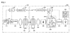
- Fig. 1 is a general structural diagram of a wireless power feeding system according to an embodiment of the present invention.
- this wireless power feeding system includes a power feeding apparatus 100 and a vehicle 200.
- Power feeding apparatus 100 includes a power supply device 110, a power sensor 115, an impedance matching box 120, a primary coil 130, a primary self-resonant coil 140, a capacitor 150, an electronic control unit (hereinafter referred to as "ECU") 160, and a communication device 170.
- ECU electronice control unit
- Power supply device 110 generates power having a prescribed frequency.
- power supply device 110 receives power from a not-shown system power supply, and generates power having a prescribed frequency of between 1 MHz and a little more than 10 MHz.
- Power supply device 110 controls the generation and interruption of power and output power in accordance with an instruction received from ECU 160.
- Power sensor 115 detects traveling wave power and reflected power in power supply device 110, and outputs the detected values to ECU 160.
- the traveling wave power is power output from power supply device 110.
- the reflected power is power output from power supply device 110 and reflected back to power supply device 110.
- a variety of known sensors capable of detecting the traveling wave power and the reflected power in the power supply device can be used as power sensor 115.
- Impedance matching box 120 is provided between power supply device 110 and primary coil 130, and configured to be able to vary the inner impedance. Impedance matching box 120 varies the impedance in accordance with an instruction received from ECU 160, to match an input impedance of a resonant system including primary coil 130, primary self-resonant coil 140 and capacitor 150, and a secondary self-resonant coil 210, a capacitor 220 and a secondary coil 230 of vehicle 200 (described later) to an output impedance of power supply device 110.
- Fig. 2 is a circuit diagram illustrating an example of a circuit configuration of impedance matching box 120 shown in Fig. 1 .
- impedance matching box 120 includes variable capacitors 122, 124, and a coil 126.
- Variable capacitor 122 is connected in parallel to power supply device 110 ( Fig. 1 ).
- Variable capacitor 124 is connected in parallel to primary coil 130 ( Fig. 1 ).
- Coil 126 is connected on one of a pair of power lines provided between power supply device 110 and primary coil 130, between connection nodes of variable capacitors 122 and 124.
- impedance matching box 120 the impedance varies due to a change in capacity of at least one of variable capacitors 122 and 124 in accordance with an instruction received from ECU 160 ( Fig. 1 ). In this manner, impedance matching box 120 matches the input impedance of the resonant system to the output impedance of power supply device 110 in accordance with the instruction received from ECU 160.
- coil 126 may be formed of a variable coil, and the impedance may be varied by varying the inductance of the variable coil.
- primary coil 130 is provided substantially coaxially with primary self-resonant coil 140 at a prescribed distance from primary self-resonant coil 140.
- Primary coil 130 is magnetically coupled to primary self-resonant coil 140 by electromagnetic induction, and supplies high-frequency power supplied from power supply device 110 to primary self-resonant coil 140 by electromagnetic induction.
- Primary self-resonant coil 140 receives the power from primary coil 130 by electromagnetic induction, and transmits the power to secondary self-resonant coil 210 (described later) mounted on vehicle 200 by resonating with secondary self-resonant coil 210 through an electromagnetic field.
- Primary self-resonant coil 140 is provided with capacitor 150.
- Capacitor 150 is connected between opposing ends of primary self-resonant coil 140, for example.
- the coil diameter and turns of primary self-resonant coil 140 and the capacity of capacitor 150 are designed as appropriate to attain a high Q value (e.g., Q > 100), a high coupling factor ⁇ and the like.
- Primary coil 130 is provided to facilitate power feeding from power supply device 110 to primary self-resonant coil 140, and power supply device 110 may be directly connected to primary self-resonant coil 140 without providing primary coil 130.
- capacitor 150 may not be provided by utilizing a stray capacitance of primary self-resonant coil 140.
- ECU 160 receives the detected values of the reflected power and the traveling wave power from power sensor 115, and receives a power receiving state of vehicle 200 received by communication device 170 from communication device 170.
- the power receiving state of vehicle 200 includes information such as a receiving voltage, a receiving current and receiving power of vehicle 200.
- ECU 160 also receives information about a state of charge (hereinafter referred to as "SOC") of a power storage device 280 (described later) mounted on vehicle 200, instructions for the start/completion of power feeding and the like from communication device 170.
- SOC state of charge
- ECU 160 then executes a prescribed process by software processing of executing a prestored program with a CPU (Central Processing Unit) and/or by hardware processing with a dedicated electronic circuit.
- a CPU Central Processing Unit
- ECU 160 controls the operation of power supply device 110.
- ECU 160 estimates a positional mismatch amount of secondary self-resonant coil 210 relative to primary self-resonant coil 140 (hereinafter simply referred to as "positional mismatch amount"), based on the power receiving state of vehicle 200 and the reflected power to power supply device 110.
- Primary self-resonant coil 140 and secondary self-resonant coil 210 are provided such that their central axes are parallel with each other, and an offset amount of the central axis of secondary self-resonant coil 210 relative to the central axis of primary self-resonant coil 140 is referred to as "positional mismatch amount.”
- ECU 160 adjusts the impedance of impedance matching box 120 based on the estimated positional mismatch amount.
- Communication device 170 is a communication interface for conducting communications with vehicle 200.
- Communication device 170 receives the power receiving state of vehicle 200 and the information such as the SOC of power storage device 280 from vehicle 200, for output to ECU 160.
- communication device 170 receives an instruction for the start of a series of process steps including the estimation of the positional mismatch amount and impedance adjustment (hereinafter simply referred to as "adjustment process"), and an instruction for the start of substantial power feeding for charging power storage device 280 from ECU 160, for transmission to vehicle 200.
- Vehicle 200 includes secondary self-resonant coil 210, capacitor 220, secondary coil 230, a rectifier 240, a switching device 250, a charger 270, power storage device 280, and a motive power output device 285.
- Vehicle 200 further includes a voltage sensor 262, a current sensor 264, an ECU 290, and a communication device 300.
- Secondary self-resonant coil 210 receives power from primary self-resonant coil 140 in power feeding apparatus 100 by resonating with primary self-resonant coil 140 through an electromagnetic field. Secondary self-resonant coil 210 is provided with capacitor 220. Capacitor 220 is connected between opposing ends of secondary self-resonant coil 210, for example. The coil diameter and turns of secondary self-resonant coil 210 and the capacity of capacitor 220 are designed as appropriate to attain a high Q value (e.g., Q > 100), a high coupling factor ⁇ and the like.
- a high Q value e.g., Q > 100
- Secondary coil 230 is provided substantially coaxially with secondary self-resonant coil 210 at a prescribed distance from secondary self-resonant coil 210. Secondary coil 230 can be magnetically coupled to secondary self-resonant coil 210 by electromagnetic induction, and extracts the power received by secondary self-resonant coil 210 by electromagnetic induction, for output to rectifier 240.
- Secondary coil 230 is provided to facilitate the extraction of power from secondary self-resonant coil 210, and rectifier 240 may be directly connected to secondary self-resonant coil 210 without providing secondary coil 230.
- capacitor 220 may not be provided by utilizing a stray capacitance of secondary self-resonant coil 210.
- Rectifier 240 rectifies the power (alternating current) output from secondary coil 230.
- Charger 270 converts the voltage of direct current power output from rectifier 240 to a charging voltage of power storage device 280, for output to power storage device 280.
- Power storage device 280 is a rechargeable direct current power supply, and formed of a secondary battery such as a lithium-ion battery or a nickel-metal hydride battery.
- Power storage device 280 stores the power received from charger 270, and also stores regenerative power generated by motive power output device 285.
- Power storage device 280 then supplies the stored power to motive power output device 285.
- a capacitor having a large capacity can be employed as power storage device 280.
- Motive power output device 285 generates a driving force for running of vehicle 200 by using the power stored in power storage device 280.
- motive power output device 285 includes an inverter for receiving power from power storage device 280, a motor driven by the inverter, drive wheels driven by the motor and the like, for example.
- Motive power output device 285 may include a power generator for charging power storage device 280, and an engine capable of driving the power generator.
- Switching device 250 is provided between rectifier 240 and charger 270.
- Switching device 250 includes relays 252, 254, and a resistor element 256.
- Relay 252 is provided on a power line between rectifier 240 and charger 270.
- Relay 254 and resistor element 256 are connected in series between a pair of power lines between rectifier 240 and charger 270, closer to rectifier 240 relative to relay 252.
- relays 252 and 254 are turned on and off, respectively.
- relays 252 and 254 are turned off and on, respectively.
- Switching device 250 is to disconnect power storage device 280 whose impedance varies with the SOC and to connect resistor element 256 having a prescribed impedance, in order to estimate the positional mismatch amount and adjust the impedance with stability.
- Voltage sensor 262 detects a receiving voltage V rectified by rectifier 240, and outputs the detected value to ECU 290.
- Current sensor 264 detects a receiving current I output from rectifier 240, and outputs the detected value to ECU 290.
- ECU 290 receives the detected values of receiving voltage V and receiving current I from voltage sensor 262 and current sensor 264, respectively. ECU 290 also receives an instruction for the start of the adjustment process and an instruction for the start of charging of power storage device 280 from communication device 300. ECU 290 then controls the operation of switching device 250 and charger 270 in accordance with the instructions by software processing of executing a prestored program with a CPU and/or by hardware processing with a dedicated electronic circuit.
- Communication device 300 is a communication interface for conducting communications with power feeding apparatus 100.
- Communication device 300 receives the power receiving state of vehicle 200 and the information such as the SOC of power storage device 280 from ECU 290, for transmission to power feeding apparatus 100.
- communication device 300 receives an instruction for the start of the adjustment process, and an instruction for the start of charging of power storage device 280, for output to ECU 290.
- power feeding apparatus 100 feeds power to vehicle 200 by resonance between primary self-resonant coil 140 and secondary self-resonant coil 210 through an electromagnetic field.
- the power receiving state is detected in vehicle 200
- the reflected power to power supply device 110 is detected in power feeding apparatus 100.
- a positional mismatch amount is estimated based on the power receiving state of vehicle 200 and the reflected power.
- the impedance of impedance matching box 120 is adjusted such that the input impedance of the resonant system matches with the output impedance of power supply device 110.
- Fig. 3 is a diagram for explaining the principles of power transmission by resonance. Referring to Fig. 3 , this resonance is such that, when two LC resonant coils having the same natural frequency resonate with each other in an electromagnetic field (near field) in the same way that two tuning forks resonate with each other, power is transmitted from one of the coils to the other coil through the electromagnetic field.
- primary coil 130 is connected to power supply device 110, and high-frequency power of between 1 MHz and a little more than 10 MHz is fed to primary self-resonant coil 140 magnetically coupled to primary coil 130 by electromagnetic induction.
- Primary self-resonant coil 140 forms an LC resonator together with capacitor 150, and resonates with secondary self-resonant coil 210 having a resonant frequency the same as that of primary self-resonant coil 140 through an electromagnetic field (near field). Consequently, energy (power) is transferred from primary self-resonant coil 140 to secondary self-resonant coil 210 through the electromagnetic field.
- the energy (power) transferred to secondary self-resonant coil 210 is extracted by secondary coil 230 magnetically coupled to secondary self-resonant coil 210 by electromagnetic induction, and supplied to a load 350 subsequent to rectifier 240 ( Fig. 1 ).
- the power transmission by resonance is implemented when a Q value indicating the resonance strength of primary self-resonant coil 140 and secondary self-resonant coil 210 is higher than 100, for example.
- Fig. 4 is a functional block diagram of ECU 160 in power feeding apparatus 100 shown in Fig. 1 .
- ECU 160 includes a communication control unit 400, a power control unit 410, a positional mismatch amount estimation unit 420, and a matching box adjustment unit 430.
- Communication control unit 400 controls the communication between communication device 170 ( Fig. 1 ) and vehicle 200. Specifically, communication control unit 400 establishes communication between communication device 170 and communication device 300 in vehicle 200. In addition, communication control unit 400 transmits an instruction for the start of the adjustment process prior to charging of power storage device 280 ( Fig. 1 ) in vehicle 200 by power feeding apparatus 100, and an instruction for the start of substantial power feeding for charging power storage device 280 subsequent to the completion of the adjustment process, to vehicle 200 via communication device 170. Communication control unit 400 also receives the power receiving state of vehicle 200 and information about the SOC of power storage device 280, instructions for the start/completion of power feeding and the like, from vehicle 200 via communication device 170.
- Power control unit 410 controls the power fed to vehicle 200 by controlling power supply device 110. During the adjustment process, power control unit 410 controls power supply device 110 to output power (power for adjustment) lower than that during the substantial power feeding for charging power storage device 280.
- Positional mismatch amount estimation unit 420 estimates a positional mismatch amount ⁇ of secondary self-resonant coil 210 relative to primary self-resonant coil 140, based on the receiving voltage included in the power receiving state received from vehicle 200 and the reflected power detected by power sensor 115 ( Fig. 1 ).
- Fig. 5 is a diagram illustrating relation between the receiving voltage and the reflected power, and the positional mismatch amount ⁇ . Referring to Fig. 5 , when the positional mismatch amount ⁇ is small, the receiving voltage in vehicle 200 is high and the reflected power in power feeding apparatus 100 is low. When the positional mismatch amount ⁇ is great, on the other hand, the receiving voltage is low and the reflected power is high.
- a map or the like is prepared by obtaining in advance the relation between the receiving voltage and the reflected power, and the positional mismatch amount, and the positional mismatch amount ⁇ is estimated based on the receiving voltage and the reflected power detected during power transmission from power feeding apparatus 100 to vehicle 200, by using the map or the like.
- receiving power can be used instead of the receiving voltage. That is, when the positional mismatch amount ⁇ is small, the receiving power in vehicle 200 is high and the reflected power in power feeding apparatus 100 is low. When the positional mismatch amount ⁇ is great, on the other hand, the receiving power is low and the reflected power is high. Accordingly, a map or the like may be prepared by obtaining in advance the relation between the receiving power and the reflected power, and the positional mismatch amount, and the positional mismatch amount ⁇ may be estimated based on the receiving power and the reflected power detected during power transmission from power feeding apparatus 100 to vehicle 200, by using the map or the like.
- matching box adjustment unit 430 adjusts the impedance of impedance matching box 120 ( Figs. 1 and 2 ) to match the input impedance of the resonant system to the output impedance of power supply device 110, based on the positional mismatch amount ⁇ estimated by positional mismatch amount estimation unit 420.
- Fig. 6 is a diagram illustrating an example of relation between the positional mismatch amount ⁇ and an adjustment value of impedance matching box 120.
- C1 and C2 represent adjustment values of variable capacitors 122 and 124 ( Fig. 2 ), respectively. Adjustment values C1 and C2 vary in this manner with the positional mismatch amount ⁇ .
- a map or the like is prepared by obtaining in advance the relation between the positional mismatch amount ⁇ and adjustment values C1, C2, and the impedance of impedance matching box 120 is adjusted based on the positional mismatch amount ⁇ estimated based on the receiving voltage and the reflected power, by using the map or the like.
- power control unit 410 controls power supply device 110 to perform substantial power feeding for charging power storage device 280 in vehicle 200.
- Fig. 7 is a flowchart for explaining the process executed by ECU 160 in power feeding apparatus 100.
- ECU 160 determines whether or not communication with vehicle 200 has been established (step S10). If the communication with vehicle 200 has not been established, the process proceeds to step S120 without execution of a series of subsequent steps.
- step S 10 If it is determined in step S 10 that the communication with vehicle 200 has been established (YES in step S10), ECU 160 transmits an instruction for the start of the adjustment process to vehicle 200 via communication device 170 ( Fig. 1 ) (step S20). In vehicle 200, upon receiving this instruction, relays 252 and 254 ( Fig. 1 ) are turned off and on, respectively. As a result, resistor element 256 is electrically connected, and power storage device 280 is electrically disconnected.
- ECU 160 controls power supply device 110 to output the power for adjustment (step S30).
- This power for adjustment is prescribed power lower than that during the substantial power feeding for charging power storage device 280.
- ECU 160 receives the power receiving state (receiving voltage, receiving current, receiving power and the like) of the secondary side (vehicle) via communication device 170 (step S40). ECU 160 further receives the reflected power to power supply device 110 detected by power sensor 115 ( Fig. 1 ) from power sensor 115 (step S50).
- ECU 160 estimates a positional mismatch amount ⁇ based on the received receiving voltage and the detected reflected power, by using the map prepared in advance for estimating the positional mismatch amount, which indicates the relation between the receiving voltage of vehicle 200 and the reflected power in power feeding apparatus 100, and the positional mismatch amount (step S60). Further, ECU 160 adjusts impedance matching box 120 based on the positional mismatch amount ⁇ estimated in step S60, by using the map prepared in advance for adjusting the matching box, which indicates the relation between the positional mismatch amount of secondary self-resonant coil 210 relative to primary self-resonant coil 140 and the adjustment value of impedance matching box 120 (step S70).
- ECU 160 determines whether or not the reflected power and the receiving power of vehicle 200 are within a prescribed range (step S80). This determination process is to determine whether or not the magnitudes of the reflected power and the receiving power are appropriate relative to the power output from power supply device 110 (traveling wave power).
- ECU 160 transmits an instruction for the start of substantial power feeding for charging power storage device 280 to vehicle 200 via communication device 170 ( Fig. 1 ) (step S90).
- vehicle 200 upon receiving this instruction, relays 252 and 254 are turned on and off, respectively.
- charger 270 is electrically connected to rectifier 240, and resistor element 256 is electrically disconnected.
- ECU 160 controls power supply device 110 to output charging power for charging power storage device 280 (step S100).
- step S80 If it is determined in step S80 that the reflected power and the receiving power are not within the prescribed range (NO in step S80), on the other hand, ECU 160 stops power supply device 110, and interrupts the charging of power storage device 280 by power feeding apparatus 100 (step S110).
- the positional mismatch amount ⁇ of secondary self-resonant coil 210 relative to primary self-resonant coil 140 is estimated based on the power receiving state of vehicle 200 and the reflected power in power feeding apparatus 100. Therefore, this embodiment can eliminate the need for a distance sensor for measuring the distance between primary self-resonant coil 140 and secondary self-resonant coil 210.
- the impedance of impedance matching box 120 is adjusted based on the estimated positional mismatch amount ⁇ . According to this embodiment, therefore, reduction in power transmission efficiency can be suppressed.
- ECU 160 in power feeding apparatus 100 estimates the positional mismatch amount ⁇ in the above embodiment
- ECU 290 in vehicle 200 may estimate the positional mismatch amount ⁇ .
- a detected value of the reflected power is transmitted from power feeding apparatus 100 to vehicle 200, and an estimated result of the positional mismatch amount ⁇ is transmitted from vehicle 200 to power feeding apparatus 100.
- the position of vehicle 200 relative to power feeding apparatus 100 may be adjusted based on the estimated positional mismatch amount ⁇ .
- an impedance matching box may be provided in secondary-side vehicle 200.
- a positional mismatch amount ⁇ can be estimated based on the receiving voltage (or receiving power) and the reflected power, and the impedance matching box in vehicle 200 can be adjusted based on the estimated result, as in the above embodiment.
- the power transmission unit and the power reception unit may be formed of a pair of high dielectric disks.
- the high dielectric disks are made of a high dielectric constant material such as TiO 2 , BaTi 4 O 9 or LiTaO 3 .
- primary coil 130, primary self-resonant coil 140 and capacitor 150 form an example of "power transmission unit” in the present invention
- secondary self-resonant coil 210, capacitor 220 and secondary coil 230 form an example of "power reception unit” in the present invention
- Power sensor 115 corresponds to an example of “detection device for detecting reflected power” in the present invention
- ECU 160 positional mismatch amount estimation unit 420
- impedance matching box 120 corresponds to an example of "impedance varying device” in the present invention
- ECU 160 matching box adjustment unit 430
- voltage sensor 262 and current sensor 264 correspond to an example of "detection device for detecting a power receiving state" in the present invention.
- 100 power feeding apparatus 110 power supply device; 115 power sensor; 120 impedance matching box; 122, 124 variable capacitor; 126 coil; 130 primary coil; 140 primary self-resonant coil; 150, 220 capacitor; 160, 290 ECU; 170, 300 communication device; 200 vehicle; 230 secondary coil; 240 rectifier; 250 switching device; 252, 254 relay; 256 resistor element; 262 voltage sensor; 264 current sensor; 270 charger; 280 power storage device; 285 motive power output device; 350 load; 400 communication control unit; 410 power control unit; 420 positional mismatch amount estimation unit; 430 matching box adjustment unit
Landscapes
- Engineering & Computer Science (AREA)
- Power Engineering (AREA)
- Transportation (AREA)
- Mechanical Engineering (AREA)
- Computer Networks & Wireless Communication (AREA)
- Life Sciences & Earth Sciences (AREA)
- Sustainable Development (AREA)
- Sustainable Energy (AREA)
- Electric Propulsion And Braking For Vehicles (AREA)
- Charge And Discharge Circuits For Batteries Or The Like (AREA)
- Current-Collector Devices For Electrically Propelled Vehicles (AREA)
Abstract
Description
- The present invention relates to a wireless power feeding apparatus, a vehicle, and a method of controlling a wireless power feeding system, and more particularly to a wireless power feeding apparatus for feeding power in a contactless manner by resonance between a power transmission unit and a power reception unit through an electromagnetic field, a vehicle receiving the power from the apparatus, and a method of controlling a wireless power feeding system.
- Electrically powered vehicles such as electric vehicles and hybrid vehicles have attracted a lot of attention as environmentally friendly vehicles. These vehicles incorporate a motor for generating a driving force for running, and a rechargeable power storage device for storing power supplied to the motor. A hybrid vehicle is a vehicle incorporating a motor as well as an internal combustion engine as a driving source, a vehicle incorporating a power storage device as well as a fuel cell as a direct current power supply for driving the vehicle, or the like.
- As with an electric vehicle, a hybrid vehicle having a vehicle-mounted power storage device that can be charged from a power supply outside of the vehicle is known. For example, a so-called "plug-in hybrid vehicle" is known in which a power storage device can be charged from a power supply at an ordinary household by connecting a power supply outlet provided at the house to a charging inlet provided on the vehicle by a charging cable.
- Wireless power transmission without using a power cord or a power transmission cable has been receiving attention in recent years as a power transmission method. Power transmission using electromagnetic induction, power transmission using a microwave, and power transmission by resonance are three dominant techniques for wireless power transmission.
- The resonance is a wireless power transmission technique for causing a pair of resonators (e.g., a pair of coils) to resonate with each other in an electromagnetic field (near field) to transmit power through the electromagnetic field, and can transmit a large amount of power of several kW across a relatively long distance (e.g., several meters).
- Japanese Patent Laying-Open No.
2010-141976 - According to this wireless power transmission apparatus, power can be efficiently supplied from the alternating current power source to the load without changing the frequency of the alternating current power source even if the distance between the resonant coils or the load receiving the power changes (see PTL 1).
-
- PTL 1:
Japanese Patent Laying-Open No. 2010-141976 - PTL 2: Japanese Patent Laying-Open No.
2010-119246 - If a positional mismatch of a secondary-side resonant coil relative to a primary-side resonant coil occurs, the impedance of a resonant system varies dues to the change in distance between the coils, resulting in lower power transmission efficiency from a power feeding apparatus to a vehicle. In the wireless power transmission apparatus disclosed in the above publication, a distance sensor measures the distance between the primary-side resonant coil and the secondary-side resonant coil, and the impedance varying circuit adjusts the impedance based on the measurement result.
- However, because the distance sensor for measuring the distance between the primary-side resonant coil and the secondary-side resonant coil is separately provided, an increase in equipment cost results.
- An object of the present invention, therefore, is to eliminate the need for a distance sensor for measuring a distance between a power transmission unit and a power reception unit in a wireless power feeding system for feeding power in a contactless manner by resonance between the power transmission unit and the power reception unit through an electromagnetic field.
- According to the present invention, a wireless power feeding apparatus for feeding power in a contactless manner to a power reception device including a power reception unit includes a power supply device, a power transmission unit, a detection device, a communication device, and an estimation unit. The power supply device generates power having a prescribed frequency. The power transmission unit receives the power from the power supply device, and transmits the power in a contactless manner to the power reception unit by resonating with the power reception unit through an electromagnetic field. The detection device detects reflected power to the power supply device. The communication device receives a power receiving state of the power reception device. The estimation unit estimates a positional mismatch amount of the power reception unit relative to the power transmission unit based on the power receiving state and the reflected power, by using relation obtained in advance between the power receiving state and the reflected power, and the positional mismatch amount.
- Preferably, the wireless power feeding apparatus further includes an impedance varying device and an impedance adjustment unit. The impedance varying device is provided between the power supply device and the power transmission unit. The impedance adjustment unit adjusts an impedance of the impedance varying device based on the positional mismatch amount, by using relation obtained in advance between the positional mismatch amount and the impedance.
- Preferably, the power receiving state is indicated by a receiving voltage of the power reception device.
- Preferably, the power receiving state is indicated by receiving power of the power reception device.
- Preferably, the power reception device is configured to be able to fix an impedance during power reception to a prescribed value in accordance with a given instruction. The communication device further transmits the instruction for fixing the impedance to the prescribed value to the power reception device while the estimation unit estimates the positional mismatch amount.
- Preferably, the power transmission unit includes a primary coil and a primary self-resonant coil, and the power reception unit includes a secondary self-resonant coil and a secondary coil. The primary coil receives the power from the power supply device. The primary self-resonant coil, to which power is fed from the primary coil by electromagnetic induction, generates the electromagnetic field. The secondary self-resonant coil receives power from the primary self-resonant coil by resonating with the primary self-resonant coil through the electromagnetic field. The secondary coil extracts the power received by the secondary self-resonant coil by electromagnetic induction for output.
- Preferably, the power reception device is mounted on a vehicle.
- According to the present invention, a vehicle capable of receiving power in a contactless manner from a power feeding apparatus including a power transmission unit includes a power reception unit, a detection device, a communication device, and an estimation unit. The power reception unit receives power in a contactless manner from the power transmission unit by resonating with the power transmission unit through an electromagnetic field. The detection device detects a power receiving state of the power reception unit. The communication device receives a detected value of reflected power in the power feeding apparatus. The estimation unit estimates a positional mismatch amount of the power reception unit relative to the power transmission unit based on the power receiving state and the reflected power, by using relation obtained in advance between the power receiving state and the reflected power, and the positional mismatch amount.
- According to the present invention, a method of controlling a wireless power feeding system for feeding power in a contactless manner from a power feeding apparatus to a power reception device is provided. The power feeding apparatus includes a power supply device and a power transmission unit. The power supply device generates power having a prescribed frequency. The power transmission unit receives the power from the power supply device, and transmits the power in a contactless manner to a power reception unit in the power reception device by resonating with the power reception unit through an electromagnetic field. The method includes the steps of detecting reflected power to the power supply device, detecting a power receiving state of the power reception device, and estimating a positional mismatch amount of the power reception unit relative to the power transmission unit based on the power receiving state and the reflected power, by using relation obtained in advance between the power receiving state and the reflected power, and the positional mismatch amount.
- Preferably, the power feeding apparatus further includes an impedance varying device provided between the power supply device and the power transmission unit. The control method further includes the step of adjusting an impedance of the impedance varying device based on the positional mismatch amount, by using relation obtained in advance between the positional mismatch amount and the impedance.
- According to the present invention, the positional mismatch amount of the power reception unit relative to the power transmission unit is estimated based on the power receiving state of the power reception device and the reflected power to the power supply device, thereby eliminating the need for a distance sensor for measuring the distance between the power transmission unit and the power reception unit.
-
-
Fig. 1 is a general structural diagram of a wireless power feeding system according to an embodiment of the present invention. -
Fig. 2 is a circuit diagram illustrating an example of a circuit configuration of an impedance matching box shown inFig. 1 . -
Fig. 3 is a diagram for explaining the principles of power transmission by resonance. -
Fig. 4 is a functional block diagram of an ECU in a power feeding apparatus shown inFig. 1 . -
Fig. 5 is a diagram illustrating relation between a receiving voltage and reflected power, and a positional mismatch amount of a secondary self-resonant coil relative to a primary self-resonant coil. -
Fig. 6 is a diagram illustrating an example of relation between the positional mismatch amount of the secondary self-resonant coil relative to the primary self-resonant coil and an adjustment value of the impedance matching box. -
Fig. 7 is a flowchart for explaining a process executed by the ECU in the power feeding apparatus. - Embodiments of the present invention will now be described in detail with reference to the drawings. It is noted that the same or corresponding parts are designated by the same reference characters in the drawings, and description thereof will not be repeated.
-
Fig. 1 is a general structural diagram of a wireless power feeding system according to an embodiment of the present invention. Referring toFig. 1 , this wireless power feeding system includes apower feeding apparatus 100 and avehicle 200. -
Power feeding apparatus 100 includes apower supply device 110, apower sensor 115, animpedance matching box 120, aprimary coil 130, a primary self-resonant coil 140, acapacitor 150, an electronic control unit (hereinafter referred to as "ECU") 160, and acommunication device 170. -
Power supply device 110 generates power having a prescribed frequency. As an example,power supply device 110 receives power from a not-shown system power supply, and generates power having a prescribed frequency of between 1 MHz and a little more than 10 MHz.Power supply device 110 controls the generation and interruption of power and output power in accordance with an instruction received fromECU 160. -
Power sensor 115 detects traveling wave power and reflected power inpower supply device 110, and outputs the detected values toECU 160. The traveling wave power is power output frompower supply device 110. The reflected power is power output frompower supply device 110 and reflected back topower supply device 110. A variety of known sensors capable of detecting the traveling wave power and the reflected power in the power supply device can be used aspower sensor 115. -
Impedance matching box 120 is provided betweenpower supply device 110 andprimary coil 130, and configured to be able to vary the inner impedance.Impedance matching box 120 varies the impedance in accordance with an instruction received fromECU 160, to match an input impedance of a resonant system includingprimary coil 130, primary self-resonant coil 140 andcapacitor 150, and a secondary self-resonant coil 210, acapacitor 220 and asecondary coil 230 of vehicle 200 (described later) to an output impedance ofpower supply device 110. -
Fig. 2 is a circuit diagram illustrating an example of a circuit configuration ofimpedance matching box 120 shown inFig. 1 . Referring toFig. 2 ,impedance matching box 120 includesvariable capacitors coil 126.Variable capacitor 122 is connected in parallel to power supply device 110 (Fig. 1 ).Variable capacitor 124 is connected in parallel to primary coil 130 (Fig. 1 ).Coil 126 is connected on one of a pair of power lines provided betweenpower supply device 110 andprimary coil 130, between connection nodes ofvariable capacitors - In
impedance matching box 120, the impedance varies due to a change in capacity of at least one ofvariable capacitors Fig. 1 ). In this manner,impedance matching box 120 matches the input impedance of the resonant system to the output impedance ofpower supply device 110 in accordance with the instruction received fromECU 160. - Although not specifically shown,
coil 126 may be formed of a variable coil, and the impedance may be varied by varying the inductance of the variable coil. - Referring again to
Fig. 1 ,primary coil 130 is provided substantially coaxially with primary self-resonant coil 140 at a prescribed distance from primary self-resonant coil 140.Primary coil 130 is magnetically coupled to primary self-resonant coil 140 by electromagnetic induction, and supplies high-frequency power supplied frompower supply device 110 to primary self-resonant coil 140 by electromagnetic induction. - Primary self-
resonant coil 140 receives the power fromprimary coil 130 by electromagnetic induction, and transmits the power to secondary self-resonant coil 210 (described later) mounted onvehicle 200 by resonating with secondary self-resonant coil 210 through an electromagnetic field. Primary self-resonant coil 140 is provided withcapacitor 150.Capacitor 150 is connected between opposing ends of primary self-resonant coil 140, for example. The coil diameter and turns of primary self-resonant coil 140 and the capacity ofcapacitor 150 are designed as appropriate to attain a high Q value (e.g., Q > 100), a high coupling factor κ and the like. -
Primary coil 130 is provided to facilitate power feeding frompower supply device 110 to primary self-resonant coil 140, andpower supply device 110 may be directly connected to primary self-resonant coil 140 without providingprimary coil 130. Alternatively,capacitor 150 may not be provided by utilizing a stray capacitance of primary self-resonant coil 140. - During power feeding from
power feeding apparatus 100 tovehicle 200,ECU 160 receives the detected values of the reflected power and the traveling wave power frompower sensor 115, and receives a power receiving state ofvehicle 200 received bycommunication device 170 fromcommunication device 170. The power receiving state ofvehicle 200 includes information such as a receiving voltage, a receiving current and receiving power ofvehicle 200. In addition to the power receiving state,ECU 160 also receives information about a state of charge (hereinafter referred to as "SOC") of a power storage device 280 (described later) mounted onvehicle 200, instructions for the start/completion of power feeding and the like fromcommunication device 170. -
ECU 160 then executes a prescribed process by software processing of executing a prestored program with a CPU (Central Processing Unit) and/or by hardware processing with a dedicated electronic circuit. - Specifically,
ECU 160 controls the operation ofpower supply device 110. In addition,ECU 160 estimates a positional mismatch amount of secondary self-resonant coil 210 relative to primary self-resonant coil 140 (hereinafter simply referred to as "positional mismatch amount"), based on the power receiving state ofvehicle 200 and the reflected power topower supply device 110. Primary self-resonant coil 140 and secondary self-resonant coil 210 are provided such that their central axes are parallel with each other, and an offset amount of the central axis of secondary self-resonant coil 210 relative to the central axis of primary self-resonant coil 140 is referred to as "positional mismatch amount."ECU 160 adjusts the impedance ofimpedance matching box 120 based on the estimated positional mismatch amount. These process steps will be described later in detail. -
Communication device 170 is a communication interface for conducting communications withvehicle 200.Communication device 170 receives the power receiving state ofvehicle 200 and the information such as the SOC ofpower storage device 280 fromvehicle 200, for output toECU 160. In addition,communication device 170 receives an instruction for the start of a series of process steps including the estimation of the positional mismatch amount and impedance adjustment (hereinafter simply referred to as "adjustment process"), and an instruction for the start of substantial power feeding for chargingpower storage device 280 fromECU 160, for transmission tovehicle 200. -
Vehicle 200 includes secondary self-resonant coil 210,capacitor 220,secondary coil 230, arectifier 240, aswitching device 250, acharger 270,power storage device 280, and a motivepower output device 285.Vehicle 200 further includes avoltage sensor 262, acurrent sensor 264, anECU 290, and acommunication device 300. - Secondary self-
resonant coil 210 receives power from primary self-resonant coil 140 inpower feeding apparatus 100 by resonating with primary self-resonant coil 140 through an electromagnetic field. Secondary self-resonant coil 210 is provided withcapacitor 220.Capacitor 220 is connected between opposing ends of secondary self-resonant coil 210, for example. The coil diameter and turns of secondary self-resonant coil 210 and the capacity ofcapacitor 220 are designed as appropriate to attain a high Q value (e.g., Q > 100), a high coupling factor κ and the like. -
Secondary coil 230 is provided substantially coaxially with secondary self-resonant coil 210 at a prescribed distance from secondary self-resonant coil 210.Secondary coil 230 can be magnetically coupled to secondary self-resonant coil 210 by electromagnetic induction, and extracts the power received by secondary self-resonant coil 210 by electromagnetic induction, for output torectifier 240. -
Secondary coil 230 is provided to facilitate the extraction of power from secondary self-resonant coil 210, andrectifier 240 may be directly connected to secondary self-resonant coil 210 without providingsecondary coil 230. Alternatively,capacitor 220 may not be provided by utilizing a stray capacitance of secondary self-resonant coil 210. -
Rectifier 240 rectifies the power (alternating current) output fromsecondary coil 230.Charger 270 converts the voltage of direct current power output fromrectifier 240 to a charging voltage ofpower storage device 280, for output topower storage device 280.Power storage device 280 is a rechargeable direct current power supply, and formed of a secondary battery such as a lithium-ion battery or a nickel-metal hydride battery.Power storage device 280 stores the power received fromcharger 270, and also stores regenerative power generated by motivepower output device 285.Power storage device 280 then supplies the stored power to motivepower output device 285. A capacitor having a large capacity can be employed aspower storage device 280. - Motive
power output device 285 generates a driving force for running ofvehicle 200 by using the power stored inpower storage device 280. Although not specifically shown, motivepower output device 285 includes an inverter for receiving power frompower storage device 280, a motor driven by the inverter, drive wheels driven by the motor and the like, for example. Motivepower output device 285 may include a power generator for chargingpower storage device 280, and an engine capable of driving the power generator. -
Switching device 250 is provided betweenrectifier 240 andcharger 270.Switching device 250 includesrelays resistor element 256.Relay 252 is provided on a power line betweenrectifier 240 andcharger 270.Relay 254 andresistor element 256 are connected in series between a pair of power lines betweenrectifier 240 andcharger 270, closer torectifier 240 relative to relay 252. - During charging of
power storage device 280 bypower feeding apparatus 100, relays 252 and 254 are turned on and off, respectively. During the adjustment process, on the other hand, relays 252 and 254 are turned off and on, respectively.Switching device 250 is to disconnectpower storage device 280 whose impedance varies with the SOC and to connectresistor element 256 having a prescribed impedance, in order to estimate the positional mismatch amount and adjust the impedance with stability. -
Voltage sensor 262 detects a receiving voltage V rectified byrectifier 240, and outputs the detected value toECU 290.Current sensor 264 detects a receiving current I output fromrectifier 240, and outputs the detected value toECU 290. -
ECU 290 receives the detected values of receiving voltage V and receiving current I fromvoltage sensor 262 andcurrent sensor 264, respectively.ECU 290 also receives an instruction for the start of the adjustment process and an instruction for the start of charging ofpower storage device 280 fromcommunication device 300.ECU 290 then controls the operation of switchingdevice 250 andcharger 270 in accordance with the instructions by software processing of executing a prestored program with a CPU and/or by hardware processing with a dedicated electronic circuit. -
Communication device 300 is a communication interface for conducting communications withpower feeding apparatus 100.Communication device 300 receives the power receiving state ofvehicle 200 and the information such as the SOC ofpower storage device 280 fromECU 290, for transmission topower feeding apparatus 100. In addition,communication device 300 receives an instruction for the start of the adjustment process, and an instruction for the start of charging ofpower storage device 280, for output toECU 290. - In this wireless power feeding system,
power feeding apparatus 100 feeds power tovehicle 200 by resonance between primary self-resonant coil 140 and secondary self-resonant coil 210 through an electromagnetic field. During the power feeding frompower feeding apparatus 100 tovehicle 200, the power receiving state is detected invehicle 200, and the reflected power topower supply device 110 is detected inpower feeding apparatus 100. Then, a positional mismatch amount is estimated based on the power receiving state ofvehicle 200 and the reflected power. Further, based on the estimated positional mismatch amount, the impedance ofimpedance matching box 120 is adjusted such that the input impedance of the resonant system matches with the output impedance ofpower supply device 110. -
Fig. 3 is a diagram for explaining the principles of power transmission by resonance. Referring toFig. 3 , this resonance is such that, when two LC resonant coils having the same natural frequency resonate with each other in an electromagnetic field (near field) in the same way that two tuning forks resonate with each other, power is transmitted from one of the coils to the other coil through the electromagnetic field. - Specifically,
primary coil 130 is connected topower supply device 110, and high-frequency power of between 1 MHz and a little more than 10 MHz is fed to primary self-resonant coil 140 magnetically coupled toprimary coil 130 by electromagnetic induction. Primary self-resonant coil 140 forms an LC resonator together withcapacitor 150, and resonates with secondary self-resonant coil 210 having a resonant frequency the same as that of primary self-resonant coil 140 through an electromagnetic field (near field). Consequently, energy (power) is transferred from primary self-resonant coil 140 to secondary self-resonant coil 210 through the electromagnetic field. The energy (power) transferred to secondary self-resonant coil 210 is extracted bysecondary coil 230 magnetically coupled to secondary self-resonant coil 210 by electromagnetic induction, and supplied to aload 350 subsequent to rectifier 240 (Fig. 1 ). The power transmission by resonance is implemented when a Q value indicating the resonance strength of primary self-resonant coil 140 and secondary self-resonant coil 210 is higher than 100, for example. -
Fig. 4 is a functional block diagram ofECU 160 inpower feeding apparatus 100 shown inFig. 1 . Referring toFig. 4 ,ECU 160 includes acommunication control unit 400, apower control unit 410, a positional mismatchamount estimation unit 420, and a matchingbox adjustment unit 430. -
Communication control unit 400 controls the communication between communication device 170 (Fig. 1 ) andvehicle 200. Specifically,communication control unit 400 establishes communication betweencommunication device 170 andcommunication device 300 invehicle 200. In addition,communication control unit 400 transmits an instruction for the start of the adjustment process prior to charging of power storage device 280 (Fig. 1 ) invehicle 200 bypower feeding apparatus 100, and an instruction for the start of substantial power feeding for chargingpower storage device 280 subsequent to the completion of the adjustment process, tovehicle 200 viacommunication device 170.Communication control unit 400 also receives the power receiving state ofvehicle 200 and information about the SOC ofpower storage device 280, instructions for the start/completion of power feeding and the like, fromvehicle 200 viacommunication device 170. -
Power control unit 410 controls the power fed tovehicle 200 by controllingpower supply device 110. During the adjustment process,power control unit 410 controlspower supply device 110 to output power (power for adjustment) lower than that during the substantial power feeding for chargingpower storage device 280. - Positional mismatch
amount estimation unit 420 estimates a positional mismatch amount δ of secondary self-resonant coil 210 relative to primary self-resonant coil 140, based on the receiving voltage included in the power receiving state received fromvehicle 200 and the reflected power detected by power sensor 115 (Fig. 1 ). -
Fig. 5 is a diagram illustrating relation between the receiving voltage and the reflected power, and the positional mismatch amount δ. Referring toFig. 5 , when the positional mismatch amount δ is small, the receiving voltage invehicle 200 is high and the reflected power inpower feeding apparatus 100 is low. When the positional mismatch amount δ is great, on the other hand, the receiving voltage is low and the reflected power is high. - Accordingly, a map or the like is prepared by obtaining in advance the relation between the receiving voltage and the reflected power, and the positional mismatch amount, and the positional mismatch amount δ is estimated based on the receiving voltage and the reflected power detected during power transmission from
power feeding apparatus 100 tovehicle 200, by using the map or the like. - Although not specifically shown, receiving power can be used instead of the receiving voltage. That is, when the positional mismatch amount δ is small, the receiving power in
vehicle 200 is high and the reflected power inpower feeding apparatus 100 is low. When the positional mismatch amount δ is great, on the other hand, the receiving power is low and the reflected power is high. Accordingly, a map or the like may be prepared by obtaining in advance the relation between the receiving power and the reflected power, and the positional mismatch amount, and the positional mismatch amount δ may be estimated based on the receiving power and the reflected power detected during power transmission frompower feeding apparatus 100 tovehicle 200, by using the map or the like. - Referring again to
Fig. 4 , matchingbox adjustment unit 430 adjusts the impedance of impedance matching box 120 (Figs. 1 and2 ) to match the input impedance of the resonant system to the output impedance ofpower supply device 110, based on the positional mismatch amount δ estimated by positional mismatchamount estimation unit 420. -
Fig. 6 is a diagram illustrating an example of relation between the positional mismatch amount δ and an adjustment value ofimpedance matching box 120. Referring toFig. 6 , C1 and C2 represent adjustment values ofvariable capacitors 122 and 124 (Fig. 2 ), respectively. Adjustment values C1 and C2 vary in this manner with the positional mismatch amount δ. - Accordingly, a map or the like is prepared by obtaining in advance the relation between the positional mismatch amount δ and adjustment values C1, C2, and the impedance of
impedance matching box 120 is adjusted based on the positional mismatch amount δ estimated based on the receiving voltage and the reflected power, by using the map or the like. - Referring again to
Fig. 4 , upon completion of the impedance adjustment,power control unit 410 controlspower supply device 110 to perform substantial power feeding for chargingpower storage device 280 invehicle 200. -
Fig. 7 is a flowchart for explaining the process executed byECU 160 inpower feeding apparatus 100. Referring toFig. 7 ,ECU 160 determines whether or not communication withvehicle 200 has been established (step S10). If the communication withvehicle 200 has not been established, the process proceeds to step S120 without execution of a series of subsequent steps. - If it is determined in step S 10 that the communication with
vehicle 200 has been established (YES in step S10),ECU 160 transmits an instruction for the start of the adjustment process tovehicle 200 via communication device 170 (Fig. 1 ) (step S20). Invehicle 200, upon receiving this instruction, relays 252 and 254 (Fig. 1 ) are turned off and on, respectively. As a result,resistor element 256 is electrically connected, andpower storage device 280 is electrically disconnected. - Then, upon receiving an answerback indicating that
resistor element 256 has been connected,ECU 160 controlspower supply device 110 to output the power for adjustment (step S30). This power for adjustment is prescribed power lower than that during the substantial power feeding for chargingpower storage device 280. - Next,
ECU 160 receives the power receiving state (receiving voltage, receiving current, receiving power and the like) of the secondary side (vehicle) via communication device 170 (step S40).ECU 160 further receives the reflected power topower supply device 110 detected by power sensor 115 (Fig. 1 ) from power sensor 115 (step S50). - Then,
ECU 160 estimates a positional mismatch amount δ based on the received receiving voltage and the detected reflected power, by using the map prepared in advance for estimating the positional mismatch amount, which indicates the relation between the receiving voltage ofvehicle 200 and the reflected power inpower feeding apparatus 100, and the positional mismatch amount (step S60). Further,ECU 160 adjustsimpedance matching box 120 based on the positional mismatch amount δ estimated in step S60, by using the map prepared in advance for adjusting the matching box, which indicates the relation between the positional mismatch amount of secondary self-resonant coil 210 relative to primary self-resonant coil 140 and the adjustment value of impedance matching box 120 (step S70). - Next,
ECU 160 determines whether or not the reflected power and the receiving power ofvehicle 200 are within a prescribed range (step S80). This determination process is to determine whether or not the magnitudes of the reflected power and the receiving power are appropriate relative to the power output from power supply device 110 (traveling wave power). - If it is determined that the reflected power and the receiving power are within the prescribed range (YES in step S80),
ECU 160 transmits an instruction for the start of substantial power feeding for chargingpower storage device 280 tovehicle 200 via communication device 170 (Fig. 1 ) (step S90). Invehicle 200, upon receiving this instruction, relays 252 and 254 are turned on and off, respectively. As a result,charger 270 is electrically connected torectifier 240, andresistor element 256 is electrically disconnected. Then,ECU 160 controlspower supply device 110 to output charging power for charging power storage device 280 (step S100). - If it is determined in step S80 that the reflected power and the receiving power are not within the prescribed range (NO in step S80), on the other hand,
ECU 160 stopspower supply device 110, and interrupts the charging ofpower storage device 280 by power feeding apparatus 100 (step S110). - As described above, in this embodiment, the positional mismatch amount δ of secondary self-
resonant coil 210 relative to primary self-resonant coil 140 is estimated based on the power receiving state ofvehicle 200 and the reflected power inpower feeding apparatus 100. Therefore, this embodiment can eliminate the need for a distance sensor for measuring the distance between primary self-resonant coil 140 and secondary self-resonant coil 210. - In this embodiment, the impedance of
impedance matching box 120 is adjusted based on the estimated positional mismatch amount δ. According to this embodiment, therefore, reduction in power transmission efficiency can be suppressed. - While
ECU 160 inpower feeding apparatus 100 estimates the positional mismatch amount δ in the above embodiment,ECU 290 invehicle 200 may estimate the positional mismatch amount δ. In this case, a detected value of the reflected power is transmitted frompower feeding apparatus 100 tovehicle 200, and an estimated result of the positional mismatch amount δ is transmitted fromvehicle 200 topower feeding apparatus 100. - While the impedance of
impedance matching box 120 is adjusted based on the estimated positional mismatch amount δ in the above description, the position ofvehicle 200 relative topower feeding apparatus 100 may be adjusted based on the estimated positional mismatch amount δ. - While
impedance matching box 120 is provided only in primary-sidepower feeding apparatus 100 in the above description, an impedance matching box may be provided in secondary-side vehicle 200. When an impedance matching box is provided invehicle 200, a positional mismatch amount δ can be estimated based on the receiving voltage (or receiving power) and the reflected power, and the impedance matching box invehicle 200 can be adjusted based on the estimated result, as in the above embodiment. - While power is transmitted by resonance between primary self-
resonant coil 140 inpower feeding apparatus 100 and secondary self-resonant coil 210 invehicle 210 in the above description, the power transmission unit and the power reception unit may be formed of a pair of high dielectric disks. The high dielectric disks are made of a high dielectric constant material such as TiO2, BaTi4O9 or LiTaO3. - In the above description,
primary coil 130, primary self-resonant coil 140 andcapacitor 150 form an example of "power transmission unit" in the present invention, and secondary self-resonant coil 210,capacitor 220 andsecondary coil 230 form an example of "power reception unit" in the present invention.Power sensor 115 corresponds to an example of "detection device for detecting reflected power" in the present invention, and ECU 160 (positional mismatch amount estimation unit 420) corresponds to an example of "estimation unit" in the present invention. - Further,
impedance matching box 120 corresponds to an example of "impedance varying device" in the present invention, and ECU 160 (matching box adjustment unit 430) corresponds to an example of "impedance adjustment unit" in the present invention. Furthermore,voltage sensor 262 andcurrent sensor 264 correspond to an example of "detection device for detecting a power receiving state" in the present invention. - It should be understood that the embodiments disclosed herein are illustrative and non-restrictive in every respect. The scope of the present invention is defined by the terms of the claims, rather than the description above, and is intended to include any modifications within the scope and meaning equivalent to the terms of the claims.
- 100 power feeding apparatus; 110 power supply device; 115 power sensor; 120 impedance matching box; 122, 124 variable capacitor; 126 coil; 130 primary coil; 140 primary self-resonant coil; 150, 220 capacitor; 160, 290 ECU; 170, 300 communication device; 200 vehicle; 230 secondary coil; 240 rectifier; 250 switching device; 252, 254 relay; 256 resistor element; 262 voltage sensor; 264 current sensor; 270 charger; 280 power storage device; 285 motive power output device; 350 load; 400 communication control unit; 410 power control unit; 420 positional mismatch amount estimation unit; 430 matching box adjustment unit
Claims (10)
- A wireless power feeding apparatus for feeding power in a contactless manner to a power reception device (200) including a power reception unit (210, 220, 230), comprising:a power supply device (110) for generating power having a prescribed frequency;a power transmission unit (130, 140, 150) for receiving the power from said power supply device, and transmitting the power in a contactless manner to said power reception unit by resonating with said power reception unit through an electromagnetic field;a detection device (115) for detecting reflected power to said power supply device;a communication device (170) for receiving a power receiving state of said power reception device; andan estimation unit (420) for estimating a positional mismatch amount of said power reception unit relative to said power transmission unit based on said power receiving state and said reflected power, by using relation obtained in advance between said power receiving state and said reflected power, and said positional mismatch amount.
- The wireless power feeding apparatus according to claim 1, further comprising:an impedance varying device (120) provided between said power supply device and said power transmission unit; andan impedance adjustment unit (430) for adjusting an impedance of said impedance varying device based on said positional mismatch amount, by using relation obtained in advance between said positional mismatch amount and said impedance.
- The wireless power feeding apparatus according to claim 1 or 2, wherein
said power receiving state is indicated by a receiving voltage of said power reception device. - The wireless power feeding apparatus according to claim 1 or 2, wherein
said power receiving state is indicated by receiving power of said power reception device. - The wireless power feeding apparatus according to claim 1 or 2, wherein
said power reception device is configured to be able to fix an impedance during power reception to a prescribed value in accordance with a given instruction, and
said communication device further transmits said instruction for fixing said impedance to said prescribed value to said power reception device while said estimation unit estimates said positional mismatch amount. - The wireless power feeding apparatus according to claim 1 or 2, wherein
said power transmission unit includesa primary coil (130) for receiving the power from said power supply device, anda primary self-resonant coil (140) to which power is fed from said primary coil by electromagnetic induction for generating said electromagnetic field, andsaid power reception unit includesa secondary self-resonant coil (210) for receiving power from said primary self-resonant coil by resonating with said primary self-resonant coil through said electromagnetic field, anda secondary coil (230) for extracting the power received by said secondary self-resonant coil by electromagnetic induction for output. - The wireless power feeding apparatus according to claim 1 or 2, wherein
said power reception device is mounted on a vehicle. - A vehicle capable of receiving power in a contactless manner from a power feeding apparatus (100) including a power transmission unit (130, 140, 150), comprising:a power reception unit (210, 220, 230) for receiving power in a contactless manner from said power transmission unit by resonating with said power transmission unit through an electromagnetic field;a detection device (262, 264) for detecting a power receiving state of said power reception unit;a communication device (300) for receiving a detected value of reflected power in said power feeding apparatus; andan estimation unit (290) for estimating a positional mismatch amount of said power reception unit relative to said power transmission unit based on said power receiving state and said reflected power, by using relation obtained in advance between said power receiving state and said reflected power, and said positional mismatch amount.
- A method of controlling a wireless power feeding system for feeding power in a contactless manner from a power feeding apparatus (100) to a power reception device (200),
said power feeding apparatus includinga power supply device (110) for generating power having a prescribed frequency, anda power transmission unit (130, 140, 150) for receiving the power from said power supply device, and transmitting the power in a contactless manner to a power reception unit (210, 220, 230) in said power reception device by resonating with said power reception unit through an electromagnetic field,said method comprising the steps of:detecting reflected power to said power supply device;detecting a power receiving state of said power reception device; andestimating a positional mismatch amount of said power reception unit relative to said power transmission unit based on said power receiving state and said reflected power, by using relation obtained in advance between said power receiving state and said reflected power, and said positional mismatch amount. - The method of controlling a wireless power feeding system according to claim 9, wherein
said power feeding apparatus further includes an impedance varying device (120) provided between said power supply device and said power transmission unit, and
said method further comprises the step of adjusting an impedance of said impedance varying device based on said positional mismatch amount, by using relation obtained in advance between said positional mismatch amount and said impedance.
Applications Claiming Priority (1)
| Application Number | Priority Date | Filing Date | Title |
|---|---|---|---|
| PCT/JP2010/071439 WO2012073349A1 (en) | 2010-12-01 | 2010-12-01 | Wireless power-transfer equipment and method for controlling vehicle and wireless power-transfer system |
Publications (4)
| Publication Number | Publication Date |
|---|---|
| EP2651008A1 true EP2651008A1 (en) | 2013-10-16 |
| EP2651008A8 EP2651008A8 (en) | 2013-12-18 |
| EP2651008A4 EP2651008A4 (en) | 2014-04-16 |
| EP2651008B1 EP2651008B1 (en) | 2016-11-23 |
Family
ID=46171334
Family Applications (1)
| Application Number | Title | Priority Date | Filing Date |
|---|---|---|---|
| EP10859617.2A Not-in-force EP2651008B1 (en) | 2010-12-01 | 2010-12-01 | Wireless power feeding apparatus, vehicle, and method of controlling wireless power feeding system |
Country Status (8)
| Country | Link |
|---|---|
| US (1) | US9536655B2 (en) |
| EP (1) | EP2651008B1 (en) |
| JP (1) | JP5083480B2 (en) |
| KR (1) | KR101318848B1 (en) |
| CN (1) | CN102640395B (en) |
| BR (1) | BR112012013116A2 (en) |
| RU (1) | RU2535951C1 (en) |
| WO (1) | WO2012073349A1 (en) |
Families Citing this family (44)
| Publication number | Priority date | Publication date | Assignee | Title |
|---|---|---|---|---|
| JP5459058B2 (en) * | 2009-11-09 | 2014-04-02 | 株式会社豊田自動織機 | Resonant contactless power transmission device |
| JP5674013B2 (en) * | 2010-10-08 | 2015-02-18 | ソニー株式会社 | Power supply device and power supply system |
| KR101222749B1 (en) * | 2010-12-14 | 2013-01-16 | 삼성전기주식회사 | Wireless power transmission apparatus and transmission method thereof |
| US9634733B2 (en) | 2010-12-24 | 2017-04-25 | Toyota Jidosha Kabushiki Kaisha | Contactless power feeding system, vehicle, power feeding facility and method of controlling contactless power feeding system |
| EP2669131B1 (en) * | 2011-01-24 | 2015-02-25 | Toyota Jidosha Kabushiki Kaisha | Hybrid vehicle |
| US10673287B2 (en) * | 2011-02-01 | 2020-06-02 | Fu Da Tong Technology Co., Ltd. | Method and supplying-end module for detecting receiving-end module |
| US11128180B2 (en) | 2011-02-01 | 2021-09-21 | Fu Da Tong Technology Co., Ltd. | Method and supplying-end module for detecting receiving-end module |
| US10038338B2 (en) | 2011-02-01 | 2018-07-31 | Fu Da Tong Technology Co., Ltd. | Signal modulation method and signal rectification and modulation device |
| US10630116B2 (en) | 2011-02-01 | 2020-04-21 | Fu Da Tong Technology Co., Ltd. | Intruding metal detection method for induction type power supply system and related supplying-end module |
| US10951063B2 (en) | 2011-02-01 | 2021-03-16 | Fu Da Tong Technology Co., Ltd. | Supplying-end module of induction type power supply system and signal detection method thereof |
| JP5793963B2 (en) | 2011-05-27 | 2015-10-14 | 日産自動車株式会社 | Non-contact power feeding device |
| JP5879748B2 (en) * | 2011-05-27 | 2016-03-08 | 日産自動車株式会社 | Non-contact power supply device, vehicle and non-contact power supply system |
| JP2013013274A (en) * | 2011-06-30 | 2013-01-17 | Yazaki Corp | Power supply system |
| WO2014002190A1 (en) * | 2012-06-26 | 2014-01-03 | 株式会社日立製作所 | Wireless power transmission apparatus and wireless power transmission system |
| JP2014011845A (en) * | 2012-06-28 | 2014-01-20 | Toyota Industries Corp | Noncontact power transmission device and power receiving apparatus |
| JP2014017894A (en) * | 2012-07-05 | 2014-01-30 | Toyota Industries Corp | Transmitting apparatus and contactless power transmission system |
| CN104521106B (en) | 2012-07-10 | 2017-06-06 | 三星电子株式会社 | Wireless power transmitter, wireless power receiver and its control method |
| US20160197494A1 (en) | 2012-09-05 | 2016-07-07 | Samsung Electronics Co., Ltd. | Wireless power transmitter for excluding cross-connected wireless power receiver and method for controlling the same |
| KR20140031780A (en) | 2012-09-05 | 2014-03-13 | 삼성전자주식회사 | Wireless power transmitter for excluding cross connected wireless power receiver and method for controlling thereof |
| US20140084688A1 (en) * | 2012-09-21 | 2014-03-27 | Samsung Electronics Co. Ltd | Method and apparatus for wireless power transmission |
| JP6094204B2 (en) * | 2012-12-20 | 2017-03-15 | Tdk株式会社 | Wireless power transmission system |
| KR102123829B1 (en) | 2013-01-22 | 2020-06-18 | 삼성전자주식회사 | Wireless power transmission apparatus and wireless power transmission method |
| JP6167395B2 (en) * | 2013-03-22 | 2017-07-26 | パナソニックIpマネジメント株式会社 | Power supply device |
| WO2014173262A1 (en) * | 2013-04-22 | 2014-10-30 | Mediatek Inc. | Method for communicating electronic apparatus with adaptor via specific communication interface to adjust operation behavior of adaptor, electronic apparatus, and corresponding adaptor |
| JP6217211B2 (en) * | 2013-07-23 | 2017-10-25 | 株式会社Ihi | Non-contact power supply apparatus and system |
| JP6276532B2 (en) * | 2013-07-29 | 2018-02-07 | キヤノン株式会社 | Power receiving device, power transmitting device, control method thereof, and program |
| WO2015029221A1 (en) * | 2013-08-30 | 2015-03-05 | パイオニア株式会社 | Non-contact power reception system, non-contact power transmission system, control method, computer program, and recording medium |
| MX346611B (en) * | 2013-09-26 | 2017-03-27 | Nissan Motor | Wireless charging system and power transmission device. |
| JP6217388B2 (en) * | 2013-12-27 | 2017-10-25 | トヨタ自動車株式会社 | Power receiving device and vehicle including the same |
| KR101943082B1 (en) * | 2014-01-23 | 2019-04-18 | 한국전자통신연구원 | Wireless power transmission device, wireless power receiving device and wireless power transmission system |
| CN103812201A (en) * | 2014-03-13 | 2014-05-21 | 宿迁学院 | Battery car wireless intelligent charger and charging method |
| CN104648177B (en) * | 2015-02-11 | 2016-09-21 | 吴宗群 | A kind of automobile wireless charging telescopic device |
| TWI580150B (en) * | 2015-05-15 | 2017-04-21 | 立錡科技股份有限公司 | Resonant Wireless Power Receiver Circuit and Control Circuit and Wireless Power Conversion Method thereof |
| KR102048652B1 (en) | 2016-05-23 | 2019-11-25 | 닛산 지도우샤 가부시키가이샤 | Coil position detection method and non-contact feeding system of non-contact feeding system |
| JP6610583B2 (en) * | 2017-03-09 | 2019-11-27 | Tdk株式会社 | Wireless power transmission system |
| JP6503398B2 (en) * | 2017-03-31 | 2019-04-17 | 本田技研工業株式会社 | Contactless power transmission system |
| CN110546853A (en) * | 2017-04-24 | 2019-12-06 | 三菱电机工程技术株式会社 | Resonance type power receiving device |
| DE112017007760T5 (en) * | 2017-07-20 | 2020-04-09 | Tdk Corporation | Primary assembly for use in a wireless power transmission system, positioning system, and method for determining a distance between a primary assembly and a secondary assembly |
| US10391875B2 (en) | 2017-07-21 | 2019-08-27 | Witricity Corporation | Vehicle alignment for wireless charging |
| JP6820905B2 (en) * | 2017-12-29 | 2021-01-27 | ゴゴロ インク | Systems and methods for managing exchangeable energy storage stations |
| CN108556644B (en) * | 2018-03-20 | 2019-11-05 | 广州汽车集团股份有限公司 | A kind of hybrid vehicle distance increasing unit power follow-up control method and system |
| US20190386513A1 (en) * | 2018-06-14 | 2019-12-19 | Integrated Device Technology, Inc. | Bi-directional communication in wireless power transmission |
| CN109552086B (en) * | 2018-12-18 | 2024-03-19 | 深圳市信维通信股份有限公司 | Wireless charging system of electric automobile and control method thereof |
| CN117652075A (en) * | 2021-09-29 | 2024-03-05 | 三星电子株式会社 | Wireless power transmitter including reduced-size inverter for reducing harmonics |
Citations (2)
| Publication number | Priority date | Publication date | Assignee | Title |
|---|---|---|---|---|
| US20100045114A1 (en) * | 2008-08-20 | 2010-02-25 | Sample Alanson P | Adaptive wireless power transfer apparatus and method thereof |
| US20100187913A1 (en) * | 2008-08-20 | 2010-07-29 | Smith Joshua R | Wireless power transfer apparatus and method thereof |
Family Cites Families (77)
| Publication number | Priority date | Publication date | Assignee | Title |
|---|---|---|---|---|
| US4800328A (en) * | 1986-07-18 | 1989-01-24 | Inductran Inc. | Inductive power coupling with constant voltage output |
| DE4236286A1 (en) | 1992-10-28 | 1994-05-05 | Daimler Benz Ag | Method and arrangement for automatic contactless charging |
| US5461298A (en) | 1993-01-15 | 1995-10-24 | Hughes Aircraft Company | Automatic electric vehicle charging system |
| US5617003A (en) | 1995-03-24 | 1997-04-01 | Kabushiki Kaisha Toyoda Jidoshokki Seisakusho | Method and apparatus for charging a battery of an electric vehicle |
| US5703461A (en) | 1995-06-28 | 1997-12-30 | Kabushiki Kaisha Toyoda Jidoshokki Seisakusho | Inductive coupler for electric vehicle charger |
| JP3772997B2 (en) | 1995-07-31 | 2006-05-10 | 住友電装株式会社 | Electric vehicle charging system and electromagnetic coupling device for electric vehicle charging |
| EP0788211B1 (en) | 1996-01-30 | 2002-08-28 | Sumitomo Wiring Systems, Ltd. | A connection system and a connection method |
| JPH09213378A (en) | 1996-01-30 | 1997-08-15 | Sumitomo Wiring Syst Ltd | Charge system for electric vehicle |
| JP3586955B2 (en) | 1996-02-02 | 2004-11-10 | 住友電装株式会社 | Electric vehicle charging system |
| EP0788212B1 (en) | 1996-01-30 | 2002-04-17 | Sumitomo Wiring Systems, Ltd. | Connection system and connection method for an electric automotive vehicle |
| DE19621668A1 (en) | 1996-05-30 | 1997-12-04 | Uwe Kochanneck | Multi=block robot system e.g. for logistics and power supply to electric vehicles |
| JP3683091B2 (en) | 1997-04-15 | 2005-08-17 | 本田技研工業株式会社 | Automatic vehicle steering system |
| JPH1173600A (en) | 1997-08-28 | 1999-03-16 | Nippon Soken Inc | Width direction position detection device for traveling body |
| DE19820110A1 (en) | 1998-05-06 | 1999-02-11 | Uwe Kochanneck | Multiblock robot system of multiaxle and system cell type |
| JP2000090348A (en) | 1998-09-09 | 2000-03-31 | Honda Motor Co Ltd | Battery charging device and battery returning device |
| JP2002359839A (en) | 2001-03-29 | 2002-12-13 | Matsushita Electric Ind Co Ltd | Method and device for displaying image of rearview camera |
| US6683539B2 (en) | 2001-12-27 | 2004-01-27 | Koninklijke Philips Electronics N.V. | Computer vision based parking assistant |
| JP2004229425A (en) | 2003-01-23 | 2004-08-12 | Toyota Motor Corp | Charging apparatus for vehicle, vehicle bumper, and vehicle parking system |
| JP3949073B2 (en) | 2003-03-27 | 2007-07-25 | トヨタ自動車株式会社 | Parking assistance device |
| JP2005051863A (en) | 2003-07-30 | 2005-02-24 | Toyota Motor Corp | Control unit and control method of vehicle |
| JP3851299B2 (en) | 2003-08-29 | 2006-11-29 | トヨタ自動車株式会社 | Control device for hybrid vehicle |
| JP2005313710A (en) | 2004-04-27 | 2005-11-10 | Toyota Motor Corp | Parking assist device |
| JP2006288034A (en) | 2005-03-31 | 2006-10-19 | Matsushita Electric Ind Co Ltd | Transmitter-receiver |
| US7451839B2 (en) * | 2005-05-24 | 2008-11-18 | Rearden, Llc | System and method for powering a vehicle using radio frequency generators |
| US7825543B2 (en) | 2005-07-12 | 2010-11-02 | Massachusetts Institute Of Technology | Wireless energy transfer |
| JP4921466B2 (en) | 2005-07-12 | 2012-04-25 | マサチューセッツ インスティテュート オブ テクノロジー | Wireless non-radiative energy transfer |
| US20070131505A1 (en) | 2005-07-16 | 2007-06-14 | Kim Bryan H J | Magnetic Induction Charging System for Vehicles |
| US20070042729A1 (en) * | 2005-08-16 | 2007-02-22 | Baaman David W | Inductive power supply, remote device powered by inductive power supply and method for operating same |
| JP4222355B2 (en) | 2005-09-29 | 2009-02-12 | トヨタ自動車株式会社 | PARKING ASSISTANCE DEVICE AND POWER TRANSFER METHOD BETWEEN VEHICLE AND GROUND EQUIPMENT |
| RU2297928C1 (en) | 2005-10-13 | 2007-04-27 | Государственное научное учреждение Всероссийский научно-исследовательский институт электрификации сельского хозяйства (ГНУ ВИЭСХ) | Method of and device to supply electric vehicles |
| US7602143B2 (en) | 2005-11-04 | 2009-10-13 | Peter David Capizzo | System for replenishing energy sources onboard different types of automotive vehicles |
| JP2007159359A (en) | 2005-12-08 | 2007-06-21 | Sumitomo Electric Ind Ltd | Power transfer system, power transfer device, and power transfer device mounted on vehicle |
| US8169185B2 (en) * | 2006-01-31 | 2012-05-01 | Mojo Mobility, Inc. | System and method for inductive charging of portable devices |
| US7989986B2 (en) * | 2006-03-23 | 2011-08-02 | Access Business Group International Llc | Inductive power supply with device identification |
| EP2078330A2 (en) | 2006-10-25 | 2009-07-15 | Laszlo Farkas | High power wireless resonant energy transfer system transfers energy across an airgap |
| JP2008174102A (en) | 2007-01-18 | 2008-07-31 | Toyota Motor Corp | Parking support system |
| EP2130287A1 (en) | 2007-03-27 | 2009-12-09 | Massachusetts Institute of Technology | Wireless energy transfer |
| US8030888B2 (en) | 2007-08-13 | 2011-10-04 | Pandya Ravi A | Wireless charging system for vehicles |
| RU2342761C1 (en) * | 2007-09-07 | 2008-12-27 | Российская Академия сельскохозяйственных наук Государственное научное учреждение Всероссийский научно-исследовательский институт электрификации сельского хозяйства (ГНУ ВИЭСХ РОССЕЛЬХОЗАКАДЕМИИ) | Method and device for electric energy transmission (versions) |
| JP4453741B2 (en) * | 2007-10-25 | 2010-04-21 | トヨタ自動車株式会社 | Electric vehicle and vehicle power supply device |
| KR101094253B1 (en) | 2008-04-28 | 2011-12-19 | 정춘길 | Non-contact power receier, non-contact power trasmitter related to the same and non-contact power transmitting and receiving system |
| US20090299918A1 (en) | 2008-05-28 | 2009-12-03 | Nigelpower, Llc | Wireless delivery of power to a mobile powered device |
| US20090313174A1 (en) | 2008-06-16 | 2009-12-17 | International Business Machines Corporation | Approving Energy Transaction Plans Associated with Electric Vehicles |
| US8466654B2 (en) | 2008-07-08 | 2013-06-18 | Qualcomm Incorporated | Wireless high power transfer under regulatory constraints |
| JP4911148B2 (en) * | 2008-09-02 | 2012-04-04 | ソニー株式会社 | Contactless power supply |
| DE102008046215A1 (en) | 2008-09-08 | 2009-09-17 | Daimler Ag | Vehicle e.g. electric vehicle, coupling method for charging battery of vehicle in charging station, involves superimposing shunting-auxiliary lines for assistance of coupling process after marking coupling device detected by camera |
| US9601261B2 (en) * | 2008-09-27 | 2017-03-21 | Witricity Corporation | Wireless energy transfer using repeater resonators |
| JP5258521B2 (en) | 2008-11-14 | 2013-08-07 | トヨタ自動車株式会社 | Power supply system |
| JP5308127B2 (en) | 2008-11-17 | 2013-10-09 | 株式会社豊田中央研究所 | Power supply system |
| EP2357717A1 (en) * | 2008-12-09 | 2011-08-17 | Kabushiki Kaisha Toyota Jidoshokki | Non-contact power transmission apparatus and power transmission method using a non-contact power transmission apparatus |
| JP5114371B2 (en) | 2008-12-09 | 2013-01-09 | 株式会社豊田自動織機 | Non-contact power transmission device |
| CN101764434B (en) | 2008-12-22 | 2014-05-14 | 爱信艾达株式会社 | Power reception guidance device |
| JP4835697B2 (en) | 2009-01-08 | 2011-12-14 | パナソニック電工株式会社 | Non-contact power transmission circuit |
| JP2010183813A (en) * | 2009-02-09 | 2010-08-19 | Toyota Industries Corp | Resonance type non-contact charging system |
| JP2010206866A (en) * | 2009-02-27 | 2010-09-16 | Panasonic Corp | Electronic equipment and charger |
| JP2010206966A (en) * | 2009-03-04 | 2010-09-16 | Institute Of National Colleges Of Technology Japan | Power conversion switching device and power conversion system |
| US8033349B2 (en) | 2009-03-12 | 2011-10-11 | Ford Global Technologies, Inc. | Auto-seek electrical connection for a plug-in hybrid electric vehicle |
| US9873347B2 (en) | 2009-03-12 | 2018-01-23 | Wendell Brown | Method and apparatus for automatic charging of an electrically powered vehicle |
| EP2416470B1 (en) * | 2009-03-30 | 2019-11-13 | Fujitsu Limited | Wireless power supply system, wireless power transmission device, and wireless power receiving device |
| JP4865001B2 (en) * | 2009-04-13 | 2012-02-01 | 株式会社日本自動車部品総合研究所 | Non-contact power supply equipment, non-contact power receiving device and non-contact power supply system |
| JP5554937B2 (en) * | 2009-04-22 | 2014-07-23 | パナソニック株式会社 | Contactless power supply system |
| WO2010131346A1 (en) | 2009-05-14 | 2010-11-18 | トヨタ自動車株式会社 | Non-contact power reception device and vehicle equipped with same |
| US8729735B2 (en) | 2009-11-30 | 2014-05-20 | Tdk Corporation | Wireless power feeder, wireless power receiver, and wireless power transmission system |
| JP5504009B2 (en) | 2010-03-03 | 2014-05-28 | 本田技研工業株式会社 | Electric car |
| JP5051257B2 (en) | 2010-03-16 | 2012-10-17 | トヨタ自動車株式会社 | vehicle |
| US10343535B2 (en) | 2010-04-08 | 2019-07-09 | Witricity Corporation | Wireless power antenna alignment adjustment system for vehicles |
| JP5408343B2 (en) | 2010-04-21 | 2014-02-05 | トヨタ自動車株式会社 | Vehicle parking assist device and electric vehicle including the same |
| US20110302078A1 (en) | 2010-06-02 | 2011-12-08 | Bryan Marc Failing | Managing an energy transfer between a vehicle and an energy transfer system |
| JP2012019666A (en) * | 2010-07-09 | 2012-01-26 | Sony Corp | Wireless charging device and wireless charging system |
| WO2012042902A1 (en) | 2010-10-01 | 2012-04-05 | パナソニック株式会社 | Electricity supply system for electric automobile, and electric automobile and power supply device used in said system |
| US8513915B2 (en) | 2010-10-21 | 2013-08-20 | GM Global Technology Operations LLC | Vehicle alignment for inductive charging |
| US20120217819A1 (en) | 2010-10-27 | 2012-08-30 | Equos Research Co., Ltd. | Electric power transmission system and antenna |
| EP2698899A4 (en) * | 2011-04-15 | 2014-10-15 | Nec Casio Mobile Comm Ltd | Transmitter, receiver, non-contact power transmission control method, and computer-readable recording medium |
| US20120326523A1 (en) | 2011-06-22 | 2012-12-27 | Noriyuki Fukushima | Wireless power feeder, wireless power receiver, and wireless power transmission system |
| WO2013012480A1 (en) | 2011-07-21 | 2013-01-24 | Ut-Battelle, Llc | Regulation control and energy management scheme for wireless power transfer |
| US8816637B2 (en) | 2011-10-06 | 2014-08-26 | Ford Global Technologies, Llc | Vehicle guidance system with interface |
| US8483899B2 (en) | 2011-10-06 | 2013-07-09 | Ford Global Technologies, Llc | Vehicle guidance system |
-
2010
- 2010-12-01 US US13/504,806 patent/US9536655B2/en active Active
- 2010-12-01 EP EP10859617.2A patent/EP2651008B1/en not_active Not-in-force
- 2010-12-01 BR BR112012013116A patent/BR112012013116A2/en not_active Application Discontinuation
- 2010-12-01 JP JP2012515043A patent/JP5083480B2/en not_active Expired - Fee Related
- 2010-12-01 RU RU2012122447/07A patent/RU2535951C1/en active
- 2010-12-01 KR KR1020127013995A patent/KR101318848B1/en active IP Right Grant
- 2010-12-01 WO PCT/JP2010/071439 patent/WO2012073349A1/en active Application Filing
- 2010-12-01 CN CN201080054083.2A patent/CN102640395B/en not_active Expired - Fee Related
Patent Citations (2)
| Publication number | Priority date | Publication date | Assignee | Title |
|---|---|---|---|---|
| US20100045114A1 (en) * | 2008-08-20 | 2010-02-25 | Sample Alanson P | Adaptive wireless power transfer apparatus and method thereof |
| US20100187913A1 (en) * | 2008-08-20 | 2010-07-29 | Smith Joshua R | Wireless power transfer apparatus and method thereof |
Non-Patent Citations (1)
| Title |
|---|
| See also references of WO2012073349A1 * |
Also Published As
| Publication number | Publication date |
|---|---|
| JP5083480B2 (en) | 2012-11-28 |
| EP2651008B1 (en) | 2016-11-23 |
| WO2012073349A1 (en) | 2012-06-07 |
| RU2535951C1 (en) | 2014-12-20 |
| CN102640395B (en) | 2015-05-06 |
| EP2651008A4 (en) | 2014-04-16 |
| KR20120102670A (en) | 2012-09-18 |
| US20130234503A1 (en) | 2013-09-12 |
| US9536655B2 (en) | 2017-01-03 |
| KR101318848B1 (en) | 2013-10-17 |
| JPWO2012073349A1 (en) | 2014-05-19 |
| CN102640395A (en) | 2012-08-15 |
| BR112012013116A2 (en) | 2017-03-14 |
| EP2651008A8 (en) | 2013-12-18 |
Similar Documents
| Publication | Publication Date | Title |
|---|---|---|
| US9536655B2 (en) | Wireless power feeding apparatus, vehicle, and method of controlling wireless power feeding system | |
| US9634733B2 (en) | Contactless power feeding system, vehicle, power feeding facility and method of controlling contactless power feeding system | |
| EP2677627B1 (en) | Non-contact power receiving apparatus, vehicle having the non-contact power receiving apparatus mounted therein and non-contact power supply equipment | |
| JP5211088B2 (en) | Power feeding device and vehicle power feeding system | |
| EP2330716B1 (en) | Noncontact power receiving apparatus and vehicle including the same | |
| KR101168970B1 (en) | Power supply system and electric vehicle | |
| US9283859B2 (en) | Power receiving device, power transmitting device, vehicle, and contactless power supply system | |
| KR101634889B1 (en) | Power receiving device for vehicle, vehicle provided with same, power supply apparatus, and electric-power transmission system | |
| US20140103711A1 (en) | Contactless power receiving device, vehicle equipped with the same, contactless power transmitting device, and contactless power transfer system | |
| US20140125144A1 (en) | Power transmitting device, power receiving device, vehicle, and contactless power supply system and control method for contactless power supply system | |
| JP5678852B2 (en) | Power transmission device, power transmission system, and method for controlling power transmission system | |
| KR20130096321A (en) | Contactless power supply equipment, contactless power receiver and contactless power supply system | |
| RU2461946C1 (en) | Device for non-contact power generation and transport means containing such device | |
| JP2011166931A (en) | Power receiving device and vehicle with the same |
Legal Events
| Date | Code | Title | Description |
|---|---|---|---|
| PUAI | Public reference made under article 153(3) epc to a published international application that has entered the european phase |
Free format text: ORIGINAL CODE: 0009012 |
|
| 17P | Request for examination filed |
Effective date: 20120524 |
|
| AK | Designated contracting states |
Kind code of ref document: A1 Designated state(s): AL AT BE BG CH CY CZ DE DK EE ES FI FR GB GR HR HU IE IS IT LI LT LU LV MC MK MT NL NO PL PT RO RS SE SI SK SM TR |
|
| RIN1 | Information on inventor provided before grant (corrected) |
Inventor name: ICHIKAWA, SHINJI |
|
| DAX | Request for extension of the european patent (deleted) | ||
| A4 | Supplementary search report drawn up and despatched |
Effective date: 20140314 |
|
| RIC1 | Information provided on ipc code assigned before grant |
Ipc: H02J 5/00 20060101ALI20140310BHEP Ipc: H02J 17/00 20060101AFI20140310BHEP Ipc: H02J 7/02 20060101ALI20140310BHEP |
|
| 17Q | First examination report despatched |
Effective date: 20150205 |
|
| REG | Reference to a national code |
Ref country code: DE Ref legal event code: R079 Ref document number: 602010038353 Country of ref document: DE Free format text: PREVIOUS MAIN CLASS: H02J0017000000 Ipc: H02J0007020000 |
|
| GRAP | Despatch of communication of intention to grant a patent |
Free format text: ORIGINAL CODE: EPIDOSNIGR1 |
|
| RIC1 | Information provided on ipc code assigned before grant |
Ipc: H02J 7/02 20060101AFI20160524BHEP Ipc: H02J 50/90 20160101ALI20160524BHEP Ipc: H02J 50/10 20160101ALI20160524BHEP Ipc: H02J 5/00 20160101ALI20160524BHEP |
|
| INTG | Intention to grant announced |
Effective date: 20160610 |
|
| RIN1 | Information on inventor provided before grant (corrected) |
Inventor name: ICHIKAWA, SHINJI |
|
| GRAS | Grant fee paid |
Free format text: ORIGINAL CODE: EPIDOSNIGR3 |
|
| GRAA | (expected) grant |
Free format text: ORIGINAL CODE: 0009210 |
|
| AK | Designated contracting states |
Kind code of ref document: B1 Designated state(s): AL AT BE BG CH CY CZ DE DK EE ES FI FR GB GR HR HU IE IS IT LI LT LU LV MC MK MT NL NO PL PT RO RS SE SI SK SM TR |
|
| REG | Reference to a national code |
Ref country code: GB Ref legal event code: FG4D |
|
| REG | Reference to a national code |
Ref country code: CH Ref legal event code: EP |
|
| REG | Reference to a national code |
Ref country code: IE Ref legal event code: FG4D |
|
| REG | Reference to a national code |
Ref country code: AT Ref legal event code: REF Ref document number: 848690 Country of ref document: AT Kind code of ref document: T Effective date: 20161215 |
|
| REG | Reference to a national code |
Ref country code: DE Ref legal event code: R096 Ref document number: 602010038353 Country of ref document: DE |
|
| PG25 | Lapsed in a contracting state [announced via postgrant information from national office to epo] |
Ref country code: LV Free format text: LAPSE BECAUSE OF FAILURE TO SUBMIT A TRANSLATION OF THE DESCRIPTION OR TO PAY THE FEE WITHIN THE PRESCRIBED TIME-LIMIT Effective date: 20161123 |
|
| REG | Reference to a national code |
Ref country code: LT Ref legal event code: MG4D |
|
| REG | Reference to a national code |
Ref country code: NL Ref legal event code: MP Effective date: 20161123 |
|
| REG | Reference to a national code |
Ref country code: AT Ref legal event code: MK05 Ref document number: 848690 Country of ref document: AT Kind code of ref document: T Effective date: 20161123 |
|
| PG25 | Lapsed in a contracting state [announced via postgrant information from national office to epo] |
Ref country code: NL Free format text: LAPSE BECAUSE OF FAILURE TO SUBMIT A TRANSLATION OF THE DESCRIPTION OR TO PAY THE FEE WITHIN THE PRESCRIBED TIME-LIMIT Effective date: 20161123 Ref country code: LT Free format text: LAPSE BECAUSE OF FAILURE TO SUBMIT A TRANSLATION OF THE DESCRIPTION OR TO PAY THE FEE WITHIN THE PRESCRIBED TIME-LIMIT Effective date: 20161123 Ref country code: SE Free format text: LAPSE BECAUSE OF FAILURE TO SUBMIT A TRANSLATION OF THE DESCRIPTION OR TO PAY THE FEE WITHIN THE PRESCRIBED TIME-LIMIT Effective date: 20161123 Ref country code: NO Free format text: LAPSE BECAUSE OF FAILURE TO SUBMIT A TRANSLATION OF THE DESCRIPTION OR TO PAY THE FEE WITHIN THE PRESCRIBED TIME-LIMIT Effective date: 20170223 Ref country code: GR Free format text: LAPSE BECAUSE OF FAILURE TO SUBMIT A TRANSLATION OF THE DESCRIPTION OR TO PAY THE FEE WITHIN THE PRESCRIBED TIME-LIMIT Effective date: 20170224 |
|
| PG25 | Lapsed in a contracting state [announced via postgrant information from national office to epo] |
Ref country code: HR Free format text: LAPSE BECAUSE OF FAILURE TO SUBMIT A TRANSLATION OF THE DESCRIPTION OR TO PAY THE FEE WITHIN THE PRESCRIBED TIME-LIMIT Effective date: 20161123 Ref country code: AT Free format text: LAPSE BECAUSE OF FAILURE TO SUBMIT A TRANSLATION OF THE DESCRIPTION OR TO PAY THE FEE WITHIN THE PRESCRIBED TIME-LIMIT Effective date: 20161123 Ref country code: PL Free format text: LAPSE BECAUSE OF FAILURE TO SUBMIT A TRANSLATION OF THE DESCRIPTION OR TO PAY THE FEE WITHIN THE PRESCRIBED TIME-LIMIT Effective date: 20161123 Ref country code: BE Free format text: LAPSE BECAUSE OF NON-PAYMENT OF DUE FEES Effective date: 20161231 Ref country code: ES Free format text: LAPSE BECAUSE OF FAILURE TO SUBMIT A TRANSLATION OF THE DESCRIPTION OR TO PAY THE FEE WITHIN THE PRESCRIBED TIME-LIMIT Effective date: 20161123 Ref country code: FI Free format text: LAPSE BECAUSE OF FAILURE TO SUBMIT A TRANSLATION OF THE DESCRIPTION OR TO PAY THE FEE WITHIN THE PRESCRIBED TIME-LIMIT Effective date: 20161123 Ref country code: PT Free format text: LAPSE BECAUSE OF FAILURE TO SUBMIT A TRANSLATION OF THE DESCRIPTION OR TO PAY THE FEE WITHIN THE PRESCRIBED TIME-LIMIT Effective date: 20170323 Ref country code: RS Free format text: LAPSE BECAUSE OF FAILURE TO SUBMIT A TRANSLATION OF THE DESCRIPTION OR TO PAY THE FEE WITHIN THE PRESCRIBED TIME-LIMIT Effective date: 20161123 |
|
| PG25 | Lapsed in a contracting state [announced via postgrant information from national office to epo] |
Ref country code: RO Free format text: LAPSE BECAUSE OF FAILURE TO SUBMIT A TRANSLATION OF THE DESCRIPTION OR TO PAY THE FEE WITHIN THE PRESCRIBED TIME-LIMIT Effective date: 20161123 Ref country code: SK Free format text: LAPSE BECAUSE OF FAILURE TO SUBMIT A TRANSLATION OF THE DESCRIPTION OR TO PAY THE FEE WITHIN THE PRESCRIBED TIME-LIMIT Effective date: 20161123 Ref country code: DK Free format text: LAPSE BECAUSE OF FAILURE TO SUBMIT A TRANSLATION OF THE DESCRIPTION OR TO PAY THE FEE WITHIN THE PRESCRIBED TIME-LIMIT Effective date: 20161123 Ref country code: EE Free format text: LAPSE BECAUSE OF FAILURE TO SUBMIT A TRANSLATION OF THE DESCRIPTION OR TO PAY THE FEE WITHIN THE PRESCRIBED TIME-LIMIT Effective date: 20161123 Ref country code: CZ Free format text: LAPSE BECAUSE OF FAILURE TO SUBMIT A TRANSLATION OF THE DESCRIPTION OR TO PAY THE FEE WITHIN THE PRESCRIBED TIME-LIMIT Effective date: 20161123 |
|
| REG | Reference to a national code |
Ref country code: CH Ref legal event code: PL |
|
| REG | Reference to a national code |
Ref country code: DE Ref legal event code: R097 Ref document number: 602010038353 Country of ref document: DE |
|
| PG25 | Lapsed in a contracting state [announced via postgrant information from national office to epo] |
Ref country code: SM Free format text: LAPSE BECAUSE OF FAILURE TO SUBMIT A TRANSLATION OF THE DESCRIPTION OR TO PAY THE FEE WITHIN THE PRESCRIBED TIME-LIMIT Effective date: 20161123 Ref country code: IT Free format text: LAPSE BECAUSE OF FAILURE TO SUBMIT A TRANSLATION OF THE DESCRIPTION OR TO PAY THE FEE WITHIN THE PRESCRIBED TIME-LIMIT Effective date: 20161123 Ref country code: BE Free format text: LAPSE BECAUSE OF FAILURE TO SUBMIT A TRANSLATION OF THE DESCRIPTION OR TO PAY THE FEE WITHIN THE PRESCRIBED TIME-LIMIT Effective date: 20161123 Ref country code: BG Free format text: LAPSE BECAUSE OF FAILURE TO SUBMIT A TRANSLATION OF THE DESCRIPTION OR TO PAY THE FEE WITHIN THE PRESCRIBED TIME-LIMIT Effective date: 20170223 |
|
| REG | Reference to a national code |
Ref country code: DE Ref legal event code: R084 Ref document number: 602010038353 Country of ref document: DE |
|
| PG25 | Lapsed in a contracting state [announced via postgrant information from national office to epo] |
Ref country code: MC Free format text: LAPSE BECAUSE OF FAILURE TO SUBMIT A TRANSLATION OF THE DESCRIPTION OR TO PAY THE FEE WITHIN THE PRESCRIBED TIME-LIMIT Effective date: 20161123 |
|
| PLBE | No opposition filed within time limit |
Free format text: ORIGINAL CODE: 0009261 |
|
| REG | Reference to a national code |
Ref country code: FR Ref legal event code: ST Effective date: 20170831 |
|
| STAA | Information on the status of an ep patent application or granted ep patent |
Free format text: STATUS: NO OPPOSITION FILED WITHIN TIME LIMIT |
|
| REG | Reference to a national code |
Ref country code: IE Ref legal event code: MM4A |
|
| GBPC | Gb: european patent ceased through non-payment of renewal fee |
Effective date: 20170223 |
|
| PG25 | Lapsed in a contracting state [announced via postgrant information from national office to epo] |
Ref country code: FR Free format text: LAPSE BECAUSE OF NON-PAYMENT OF DUE FEES Effective date: 20170123 Ref country code: CH Free format text: LAPSE BECAUSE OF NON-PAYMENT OF DUE FEES Effective date: 20161231 Ref country code: LI Free format text: LAPSE BECAUSE OF NON-PAYMENT OF DUE FEES Effective date: 20161231 Ref country code: LU Free format text: LAPSE BECAUSE OF NON-PAYMENT OF DUE FEES Effective date: 20161201 |
|
| 26N | No opposition filed |
Effective date: 20170824 |
|
| PG25 | Lapsed in a contracting state [announced via postgrant information from national office to epo] |
Ref country code: IE Free format text: LAPSE BECAUSE OF NON-PAYMENT OF DUE FEES Effective date: 20161201 Ref country code: SI Free format text: LAPSE BECAUSE OF FAILURE TO SUBMIT A TRANSLATION OF THE DESCRIPTION OR TO PAY THE FEE WITHIN THE PRESCRIBED TIME-LIMIT Effective date: 20161123 |
|
| PG25 | Lapsed in a contracting state [announced via postgrant information from national office to epo] |
Ref country code: GB Free format text: LAPSE BECAUSE OF NON-PAYMENT OF DUE FEES Effective date: 20170223 |
|
| PG25 | Lapsed in a contracting state [announced via postgrant information from national office to epo] |
Ref country code: HU Free format text: LAPSE BECAUSE OF FAILURE TO SUBMIT A TRANSLATION OF THE DESCRIPTION OR TO PAY THE FEE WITHIN THE PRESCRIBED TIME-LIMIT; INVALID AB INITIO Effective date: 20101201 Ref country code: CY Free format text: LAPSE BECAUSE OF FAILURE TO SUBMIT A TRANSLATION OF THE DESCRIPTION OR TO PAY THE FEE WITHIN THE PRESCRIBED TIME-LIMIT Effective date: 20161123 |
|
| PG25 | Lapsed in a contracting state [announced via postgrant information from national office to epo] |
Ref country code: IS Free format text: LAPSE BECAUSE OF FAILURE TO SUBMIT A TRANSLATION OF THE DESCRIPTION OR TO PAY THE FEE WITHIN THE PRESCRIBED TIME-LIMIT Effective date: 20161123 Ref country code: MK Free format text: LAPSE BECAUSE OF FAILURE TO SUBMIT A TRANSLATION OF THE DESCRIPTION OR TO PAY THE FEE WITHIN THE PRESCRIBED TIME-LIMIT Effective date: 20161123 |
|
| PG25 | Lapsed in a contracting state [announced via postgrant information from national office to epo] |
Ref country code: MT Free format text: LAPSE BECAUSE OF NON-PAYMENT OF DUE FEES Effective date: 20161201 |
|
| PG25 | Lapsed in a contracting state [announced via postgrant information from national office to epo] |
Ref country code: TR Free format text: LAPSE BECAUSE OF FAILURE TO SUBMIT A TRANSLATION OF THE DESCRIPTION OR TO PAY THE FEE WITHIN THE PRESCRIBED TIME-LIMIT Effective date: 20161123 |
|
| PG25 | Lapsed in a contracting state [announced via postgrant information from national office to epo] |
Ref country code: AL Free format text: LAPSE BECAUSE OF FAILURE TO SUBMIT A TRANSLATION OF THE DESCRIPTION OR TO PAY THE FEE WITHIN THE PRESCRIBED TIME-LIMIT Effective date: 20161123 |
|
| PGFP | Annual fee paid to national office [announced via postgrant information from national office to epo] |
Ref country code: DE Payment date: 20211102 Year of fee payment: 12 |
|
| REG | Reference to a national code |
Ref country code: DE Ref legal event code: R119 Ref document number: 602010038353 Country of ref document: DE |
|
| PG25 | Lapsed in a contracting state [announced via postgrant information from national office to epo] |
Ref country code: DE Free format text: LAPSE BECAUSE OF NON-PAYMENT OF DUE FEES Effective date: 20230701 |