EP2650642A2 - Micro-electro-mechanical-system (MEMS) driver - Google Patents
Micro-electro-mechanical-system (MEMS) driver Download PDFInfo
- Publication number
- EP2650642A2 EP2650642A2 EP20130001917 EP13001917A EP2650642A2 EP 2650642 A2 EP2650642 A2 EP 2650642A2 EP 20130001917 EP20130001917 EP 20130001917 EP 13001917 A EP13001917 A EP 13001917A EP 2650642 A2 EP2650642 A2 EP 2650642A2
- Authority
- EP
- European Patent Office
- Prior art keywords
- command signal
- signal
- driver
- differential
- state
- Prior art date
- Legal status (The legal status is an assumption and is not a legal conclusion. Google has not performed a legal analysis and makes no representation as to the accuracy of the status listed.)
- Granted
Links
Images


Classifications
-
- B—PERFORMING OPERATIONS; TRANSPORTING
- B81—MICROSTRUCTURAL TECHNOLOGY
- B81B—MICROSTRUCTURAL DEVICES OR SYSTEMS, e.g. MICROMECHANICAL DEVICES
- B81B7/00—Microstructural systems ; Auxiliary parts of microstructural devices or systems
- B81B7/02—Microstructural systems ; Auxiliary parts of microstructural devices or systems containing distinct electrical or optical devices of particular relevance for their function, e.g. microelectro-mechanical systems [MEMS]
-
- H—ELECTRICITY
- H03—ELECTRONIC CIRCUITRY
- H03L—AUTOMATIC CONTROL, STARTING, SYNCHRONISATION OR STABILISATION OF GENERATORS OF ELECTRONIC OSCILLATIONS OR PULSES
- H03L7/00—Automatic control of frequency or phase; Synchronisation
- H03L7/06—Automatic control of frequency or phase; Synchronisation using a reference signal applied to a frequency- or phase-locked loop
- H03L7/16—Indirect frequency synthesis, i.e. generating a desired one of a number of predetermined frequencies using a frequency- or phase-locked loop
- H03L7/18—Indirect frequency synthesis, i.e. generating a desired one of a number of predetermined frequencies using a frequency- or phase-locked loop using a frequency divider or counter in the loop
- H03L7/183—Indirect frequency synthesis, i.e. generating a desired one of a number of predetermined frequencies using a frequency- or phase-locked loop using a frequency divider or counter in the loop a time difference being used for locking the loop, the counter counting between fixed numbers or the frequency divider dividing by a fixed number
-
- G—PHYSICS
- G01—MEASURING; TESTING
- G01C—MEASURING DISTANCES, LEVELS OR BEARINGS; SURVEYING; NAVIGATION; GYROSCOPIC INSTRUMENTS; PHOTOGRAMMETRY OR VIDEOGRAMMETRY
- G01C19/00—Gyroscopes; Turn-sensitive devices using vibrating masses; Turn-sensitive devices without moving masses; Measuring angular rate using gyroscopic effects
- G01C19/56—Turn-sensitive devices using vibrating masses, e.g. vibratory angular rate sensors based on Coriolis forces
- G01C19/5642—Turn-sensitive devices using vibrating masses, e.g. vibratory angular rate sensors based on Coriolis forces using vibrating bars or beams
- G01C19/5656—Turn-sensitive devices using vibrating masses, e.g. vibratory angular rate sensors based on Coriolis forces using vibrating bars or beams the devices involving a micromechanical structure
-
- G—PHYSICS
- G01—MEASURING; TESTING
- G01C—MEASURING DISTANCES, LEVELS OR BEARINGS; SURVEYING; NAVIGATION; GYROSCOPIC INSTRUMENTS; PHOTOGRAMMETRY OR VIDEOGRAMMETRY
- G01C19/00—Gyroscopes; Turn-sensitive devices using vibrating masses; Turn-sensitive devices without moving masses; Measuring angular rate using gyroscopic effects
- G01C19/56—Turn-sensitive devices using vibrating masses, e.g. vibratory angular rate sensors based on Coriolis forces
- G01C19/5776—Signal processing not specific to any of the devices covered by groups G01C19/5607 - G01C19/5719
-
- H—ELECTRICITY
- H03—ELECTRONIC CIRCUITRY
- H03B—GENERATION OF OSCILLATIONS, DIRECTLY OR BY FREQUENCY-CHANGING, BY CIRCUITS EMPLOYING ACTIVE ELEMENTS WHICH OPERATE IN A NON-SWITCHING MANNER; GENERATION OF NOISE BY SUCH CIRCUITS
- H03B5/00—Generation of oscillations using amplifier with regenerative feedback from output to input
- H03B5/30—Generation of oscillations using amplifier with regenerative feedback from output to input with frequency-determining element being electromechanical resonator
-
- H—ELECTRICITY
- H03—ELECTRONIC CIRCUITRY
- H03H—IMPEDANCE NETWORKS, e.g. RESONANT CIRCUITS; RESONATORS
- H03H9/00—Networks comprising electromechanical or electro-acoustic elements; Electromechanical resonators
- H03H9/02—Details
- H03H9/02244—Details of microelectro-mechanical resonators
- H03H2009/02283—Vibrating means
Definitions
- Example 3 the amplifier of any one or more of Examples 1-2 optionally is configured to provide a closed-loop output signal that is modulated by the first command signal and the second command signal when the start-up signal is in a non-start-up state.
- a system can include a MEMS device and a driver configured to provide an output signal to the MEMS device.
- the driver can include a first input configured to receive a first command signal including an oscillatory command signal, a second input configured to receive a second command signal including a bias command signal, and an amplifier configured to receive a high voltage supply, the amplifier configured to provide, to the MEMS device, a closed-loop output signal responsive to both the first command signal and the second command signal in a first state, and to provide an open loop output signal configured to substantially span a voltage range of the high voltage supply in a second state.
- Example 27 can include, or can optionally be combined with any portion or combination of any portions of any one or more of Examples 1 through 26 to include, subject matter that can include means for performing any one or more of the functions of Examples 1 through 26, or a machine-readable medium including instructions that, when performed by a machine, cause the machine to perform any one or more of the functions of Examples 1 through 26.
Landscapes
- Engineering & Computer Science (AREA)
- Physics & Mathematics (AREA)
- General Physics & Mathematics (AREA)
- Radar, Positioning & Navigation (AREA)
- Remote Sensing (AREA)
- Signal Processing (AREA)
- Computer Hardware Design (AREA)
- Microelectronics & Electronic Packaging (AREA)
- Micromachines (AREA)
- Gyroscopes (AREA)
Abstract
Description
- This application claims the benefit of priority to Tao et al.,
U.S. Provisional Patent Application Serial Number 61/623,407, filed on April 12, 2012 - This application discusses, among other things, micro-electro-mechanical systems (MEMS, and more particularly drivers for MEMS devices. In an example, a driver for a micro-electro-mechanical-system (MEMS) device can include a first input configured to receive a first command signal including an oscillatory command signal, a second input configured to receive a second command signal including a bias command signal, and an amplifier configured to receive a high voltage supply, to provide, to the MEMS device, a closed-loop output signal responsive to both the first command signal and the second command signal in a first state, and to provide an open loop output signal configured to substantially span a voltage range of the high voltage supply in a second state.
- This summary is intended to provide a general overview of subject matter of the present patent application. It is not intended to provide an exclusive or exhaustive explanation of the invention. The detailed description is included to provide further information about the present patent application.
- Micro-electro-mechanical-systems (MEMS) include small mechanical devices performing electrical and mechanical functions that are fabricated using photolithography techniques similar to techniques used to fabricate integrated circuits. Some MEMS devices are sensors that can detect motion such as an accelerometer or detect angular rate such as a gyroscope. Some MEMS gyroscopes include a driver to oscillate a proof mass of the MEMS gyroscope to allow the gyroscope to sense rotation motion.
- In the drawings, which are not necessarily drawn to scale, like numerals may describe similar components in different views. Like numerals having different letter suffixes may represent different instances of similar components. The drawings illustrate generally, by way of example, but not by way of limitation, various embodiments discussed in the present document.
-
FIG. 1 illustrates generally a block diagram of an example MEMS driver integrated with a MEMS sensor system. -
FIG. 2 illustrates generally an example MEMS driver. -
FIG. 3 illustrates generally an example MEMS driver. -
FIG. 4 illustrates generally an example high-voltage amplifier. - MEMS sensors, such as MEMS gyroscopes, can provide motion detection and measurement signals using deflections of a vibrating proof mass. The proof mass deflections can be caused by a combination of movement of the vibrating proof mass and Coriolis forces resulting from rotational motion of the gyroscope. MEMS sensors can be used in a variety of small mobile electronic devices including, but not limited to, cell phones, personal digital assistants, recreational tools, such as for hiking and camping, and game controllers. The present inventors have recognized a high voltage driver for driving a MEMS proof mass that can provide improved performance, can cost less, and can use less power.
-
FIG. 1 illustrates generally a block diagram of anexample MEMS driver 107 integrated with aMEMS sensor system 100. The MEMSsensor system 100, such as aMEMS gyroscope system 100 can include aMEMS gyroscope 102 including aproof mass 103, andMEMS sensor electronics 104. In certain examples, theMEMS sensor electronics 104 can include thedriver 107, a drive sense current-to-voltage (C2V)converter 105, asense C2V converter 106 and acontroller 101. In some examples, thecontroller 101 can provide a command signal to thedriver 107. Thedrive 107 can oscillate the proof mass of theMEMS gyroscope 102 using drive electrodes (ED). Oscillations of the proof mass can affect charge on drive sense electrodes (EDS) and the charge can be converted to voltage using the drivesense C2V converter 105. The voltage received from the drivesense C2V converter 105 can provide information about the actual oscillation of thegyroscope proof mass 103. The proof mass oscillation information can be used by the receiver to control the oscillation phase and amplitude of the proof mass including providing stable oscillation amplitude. The sense electrodes can provide an indication of deflection of one or more portions of the proof mass in response to rotational movement of the gyroscope. One or moresense C2V converters 106 can convert charge of the sense electrodes (ES) to voltage. The controller can process the voltage received from the one or moresense C2V converters 106 to provide anoutput 108 indicative of rotational motion of the gyroscope. -
FIG. 2 illustrates generally anexample MEMS driver 207 that can include a first input for receiving a DC command signal (Vincm), a second input for receiving an AC command signal (Vinac), a first and second gain blocks (al, a2), a summing junction (Summer), ahigh voltage amplifier 209, and afeedback path 210. In certain examples, theMEMS driver 207 can include avoltage multiplier 211. Thevoltage multiplier 211 1 can convert a supply voltage (Vsupply) to provide the high voltage (Vhs) to thehigh voltage amplifier 209. In certain examples, theMEMS driver 207 can respond to the received command signals (Vincm, Vinac) to modulate a drive signal (Vout) to startup and maintain controlled oscillation of a MEMS sensor proof mass. In some examples, the drive signal (Vout) can include a DC component and an AC component. In certain examples, at least one gain of the first and second gain blocks (al, a2) can be programmable to provide flexibility in adjusting the performance of theMEMS driver 207, for example, to adjust theMEMS driver 207 to the particular MEMS sensor to be driven. In certain examples, thefeedback path 210 can include a third gain block (β) to provide additional adjustment flexibility. In some examples, a gain of the third gain block (β) can be programmable. - In certain examples, the
MEMS driver 207 can include a feedback switch (s1) that can be opened, in response to a state of a start-up signal (start_up), to place thedrive 207 in a start-up mode. The start-up mode, for example, can allow thehigh voltage amplifier 209 to provide an output signal that spans the rail to rail supply voltage of thehigh voltage amplifier 209 without thefeedback path 211 loading the amplifier output. In some examples, thehigh voltage amplifier 209 can provide a high, controlled, open-loop gain for providing the startup drive signal. - In certain examples, the
MEMS driver 207 does not require an external component to store high-voltage supply power. In certain examples, individually adjusting the gain of the AC and DC components of the input command signals (Vincm, Vinac) can improve control of the oscillation amplitude of a MEMS proof mass and thus increase the performance of the sensor, including increasing sensor accuracy. -
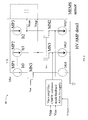
FIG. 3 illustrates generally anexample MEMS driver 307 that can include a first input for receiving a DC command signal (Vincm), a second differential input for receiving an AC command signal (Vinp, Vinn), first andsecond gain blocks differential amplifier 309, and first andsecond feedback paths first gain block 321, thesecond gain block 322 and the feedback loop gain can be set using a resistor network including Rdf, Rcml, Rcm2, and Rfb. In some examples, the DC command signal, AC command signal and the feedback signal can be summed using the resistor network and the virtual ground of the differential, high-voltage amplifier 309. In certain examples, thefeedback paths feedback paths MEMS driver 307. - In certain examples, in response to a first state of the start-up signal (start_up), the feedback switches (s1, s2) can open and the
high voltage amplifier 309 can generate a predetermined startup drive signal at an output (Voun, Voup). In certain examples, the predetermined start-up drive signal can include a waveform wherein the shape and phase of the waveform can be received from a component external to theMEMS driver 307. For example, the shape and phase information of the startup drive signal can be included in the signal received at the AC inputs (Vinp, Vinn) of theMEMS driver 307. In certain examples, the start-up drive signal can include a sinusoidal, square, or some other shaped waveform. -
FIG. 4 illustrates generally an example high-voltage amplifier 409 including three high side current sources MP1, MP2, MP3, and three low-side current sources MQ1, MQ2, MQ3. In an example, in addition to providing cascode bias to the current to voltage portion of thehigh voltage amplifier 409, three transistors MN1, MN2, MN3 can provide a voltage shield, such that the low-side current sources MQ1, MQ2, MQ3 can use low voltage components. In certain examples, the three high-side current sources MP1, MP2, MP3 can be implemented using three high voltage transistors arranged in a current mirror such thatMP 1 can be a sense transistor and MP2 and MP3 can provide a mirrored current of the current sensed by MP1. In some examples, MP2 and MP3 can amplify the sensed current ItO. In some examples, the high voltage transistors can be fabricated such that the source to drain structure can sustain high voltage and the gate can be of a regular voltage rating. Such construction can be less costly than transistor rated for high voltage. - In certain examples, the
high voltage amplifier 409 does not include common-mode sense circuitry, thus simplifying the amplifier design and saving silicon real estate. In some examples, the three high-side current sources MP1, MP2, MP3 are fixed current sources and can be the only loads pulling power from the high voltage rail in both start-up mode and regular operation. Such an example can reduce power consumption from the high voltage supply and can simplify the voltage multiplier design, including minimizing silicon area because the upper power draw from the high voltage rail is limited to the level of the three fixed current sources. In certain examples, the high-voltage amplifier 409 can minimize power consumption from the high-voltage supply rail and can minimize overall power consumption of a MEMS sensor, such as a MEMS gyroscope. In certain examples, the open loop drive of the MEMS driver can provide fast and controlled oscillation start-up without using additional power from the high voltage supply for sophisticated start-up control functions. For example, the open loop start-up control can simplify the design of the voltage multiplier which can save silicon area and can eliminate the need for an external high voltage storage component. - In Example 1, a driver for a micro-electro-mechanical-system (MEMS) device can include a first input configured to receive a first command signal including an oscillatory command signal, a second input configured to receive a second command signal including a bias command signal, and an amplifier configured to receive a high voltage supply, the amplifier configured to provide, to the MEMS device, a closed-loop output signal responsive to both the first command signal and the second command signal in a first state, and to provide an open loop output signal configured to substantially span a voltage range of the high voltage supply in a second state.
- In Example 2, the driver of Example 1 optionally includes a first feedback path electrically connected to an output of the amplifier, wherein the feedback path includes a feedback switch responsive to state of a start-up signal, wherein the amplifier provides the open loop output signal when the start-up signal is in a start-up state.
- In Example 3, the amplifier of any one or more of Examples 1-2 optionally is configured to provide a closed-loop output signal that is modulated by the first command signal and the second command signal when the start-up signal is in a non-start-up state.
- In Example 4, the driver of any one or more of Examples 1-3 optionally includes a first gain block electrically connected to the first input and a second gain block electrically connected to the second input, wherein gain provided to the first command signal by the first gain block is independent of gain provided to the second command signal by the second gain block.
- In Example 5, the driver of any one or more of Examples 1-4 optionally includes a first feedback path electrically connected to a first output of the amplifier and a second feedback path electrically connected to a second output of the amplifier, wherein the amplifier is configured to provide, to the MEMS device, a differential closed-loop output signal responsive to both the first command signal and the second command signal in the first state, and to provide a differential open loop output signal that substantially spans the voltage range of the high voltage supply in the second state.
- In Example 6, the first input of any one or more of Examples 1-5 optionally is a differential first input configured to receive a first differential command signal including a differential oscillatory command signal.
- In Example 7, the driver of any one or more of Examples 1-6 optionally includes a first gain block electrically connected to the differential first input and a second gain block electrically connected to the second input, wherein gain provided to the first differential command signal by the first gain block is independent of gain provided to the second command signal by the second gain block.
- In Example 8, the driver of any one or more of Examples 1-7 optionally includes a first summing junction and a second summing junction electrically connected to the first differential input and configured to sum the first differential command signal and the second command signal.
- In Example 9, the amplifier of any one or more of Examples 1-8 optionally includes a plurality of high side current sources and a plurality of low side current sources, wherein the high side current sources are fabricated to sustain a higher voltage than the low side current sources.
- In Example 10, a method can include generating a first command signal that includes an oscillatory command signal, generating a second command signal that includes a bias command signal, providing, at an output of the driver when the driver is in a first state, a closed-loop output signal responsive to both the first command signal and the second command signal, and providing, at the output of the driver when the driver is in a second state, an open loop output signal configured to substantially span a voltage range of a high voltage supply of the driver.
- In Example 11, the method of any one or more of Examples 1-10 optionally includes feeding back an output of the driver via a feedback switch, wherein the feedback switch is responsive to a state of a start-up signal, wherein the driver provides the open loop output signal when the start-up signal is in a start-up state.
- In Example 12, the driver of any one or more of Examples 1-11 optionally provides a closed-loop output signal that is modulated by the first command signal and the second command signal when the start-up signal is in a non-start-up state.
- In Example 13, the method of any one or more of Examples 1-12 optionally includes providing gain to the first command signal that is independent of gain provided to the second command signal.
- In Example 14, the method of any one or more of Examples 1-13 optionally includes feeding back a first output of the driver via a first feedback switch and feeding back a second output of the driver via a second feedback switch, wherein the first and second feedback switches are responsive to a state of a start-up signal, providing, to the MEMS device, a differential closed-loop output signal responsive to the both the first command signal and the second command signal in the first state, and providing a differential open loop output signal that substantially spans the voltage range of the high voltage supply in the second state.
- In Example 15, the generating a first command signal of any one or more of Examples 1-14 optionally includes applying, to a differential first input of the driver, a differential first command signal that includes a differential oscillatory command signal, and wherein the method further includes summing the differential first command signal and the second command signal.
- In Example 16, the method of any one or more of Examples 1-15 optionally includes providing gain to the differential first command signal that is independent of gain provided to the second command signal.
- In Example 17, the method of any one or more of Examples 1-16 optionally includes electrically connecting the driver to the MEMS device.
- In Example 18, a system can include a MEMS device and a driver configured to provide an output signal to the MEMS device. The driver can include a first input configured to receive a first command signal including an oscillatory command signal, a second input configured to receive a second command signal including a bias command signal, and an amplifier configured to receive a high voltage supply, the amplifier configured to provide, to the MEMS device, a closed-loop output signal responsive to both the first command signal and the second command signal in a first state, and to provide an open loop output signal configured to substantially span a voltage range of the high voltage supply in a second state.
- In Example 19, the MEMS device of any ne or more of Examples 1-18 optionally includes a MEMS gyroscope sensor.
- In Example 20, the system of any one or more of Examples 1-19 optionally includes a first feedback path electrically connected to an output of the amplifier, wherein the feedback path includes a feedback switch responsive to state of a start-up signal, wherein the amplifier provides the open loop output signal when the start-up signal is in a start-up state.
- In Example 21, the amplifier of any one or more of examples 1-20 optionally provides a closed-loop output signal that is modulated by the first command signal and the second command signal when the start-up signal is in a non-start-up state.
- In Example 22, the system of any one or more of Examples 1-21 optionally includes a first gain block electrically connected to the first input and a second gain block electrically connected to the second input, wherein gain provided to the first command signal by the first gain block is independent of gain provided to the second command signal by the second gain block.
- In Example 23, the system of any one or more of Examples 1-22 optionally includes a first feedback path electrically connected to a first output of the amplifier and a second feedback path electrically connected to a second output of the amplifier, wherein the amplifier is configured to provide, to the MEMS device, a differential closed-loop output signal responsive to the both the first command signal and the second command signal in the first state, and to provide a differential open loop output signal that substantially spans the voltage range of the high voltage supply in the second state.
- In Example 24, the first input of any one or more of Examples 1-23 optionally is a differential first input configured to receive a first differential command signal including a differential oscillatory command signal.
- In Example 25, the system of any one or more of Examples 1-24 optionally includes a first gain block electrically connected to the differential first input and a second gain block electrically connected to the second input, wherein gain provided to the first differential command signal by the first gain block is independent of gain provided to the second command signal by the second gain block.
- In Example 26, the system of any one or more of Examples 1-25 optionally includes a component separate from the MEMS device and the driver, wherein the separate component is configured to provide a startup signal waveform to the first input of the driver.
- Example 27can include, or can optionally be combined with any portion or combination of any portions of any one or more of Examples 1 through 26 to include, subject matter that can include means for performing any one or more of the functions of Examples 1 through 26, or a machine-readable medium including instructions that, when performed by a machine, cause the machine to perform any one or more of the functions of Examples 1 through 26.
- The above detailed description includes references to the accompanying drawings, which form a part of the detailed description. The drawings show, by way of illustration, specific embodiments in which the invention can be practiced. These embodiments are also referred to herein as "examples." Such examples can include elements in addition to those shown or described. However, the present inventors also contemplate examples in which only those elements shown or described are provided. Moreover, the present inventors also contemplate examples using any combination or permutation of those elements shown or described (or one or more aspects thereof), either with respect to a particular example (or one or more aspects thereof), or with respect to other examples (or one or more aspects thereof) shown or described herein.
- All publications, patents, and patent documents referred to in this document are incorporated by reference herein in their entirety, as though individually incorporated by reference. In the event of inconsistent usages between this document and those documents so incorporated by reference, the usage in the incorporated reference(s) should be considered supplementary to that of this document; for irreconcilable inconsistencies, the usage in this document controls.
- In this document, the terms "a" or "an" are used, as is common in patent documents, to include one or more than one, independent of any other instances or usages of "at least one" or "one or more." In this document, the term "or" is used to refer to a nonexclusive or, such that "A or B" includes "A but not B," "B but not A," and "A and B," unless otherwise indicated. In this document, the terms "including" and "in which" are used as the plain-English equivalents of the respective terms "comprising" and "wherein." Also, in the following claims, the terms "including" and "comprising" are open-ended, that is, a system, device, article, or process that includes elements in addition to those listed after such a term in a claim are still deemed to fall within the scope of that claim. Moreover, in the following claims, the terms "first," "second," and "third," etc. are used merely as labels, and are not intended to impose numerical requirements on their objects.
- Method examples described herein can be machine or computer-implemented at least in part. Some examples can include a computer-readable medium or machine-readable medium encoded with instructions operable to configure an electronic device to perform methods as described in the above examples. An implementation of such methods can include code, such as microcode, assembly language code, a higher-level language code, or the like. Such code can include computer readable instructions for performing various methods. The code may form portions of computer program products. Further, in an example, the code can be tangibly stored on one or more volatile, non-transitory, or non-volatile tangible computer-readable media, such as during execution or at other times. Examples of these tangible computer-readable media can include, but are not limited to, hard disks, removable magnetic disks, removable optical disks (e.g., compact disks and digital video disks), magnetic cassettes, memory cards or sticks, random access memories (RAMs), read only memories (ROMs), and the like.
- The above description is intended to be illustrative, and not restrictive. For example, the above-described examples (or one or more aspects thereof) may be used in combination with each other. Other embodiments can be used, such as by one of ordinary skill in the art upon reviewing the above description. The Abstract is provided to comply with 37 C.F.R. §1.72(b), to allow the reader to quickly ascertain the nature of the technical disclosure. It is submitted with the understanding that it will not be used to interpret or limit the scope or meaning of the claims. Also, in the above Detailed Description, various features may be grouped together to streamline the disclosure. This should not be interpreted as intending that an unclaimed disclosed feature is essential to any claim. Rather, inventive subject matter may lie in less than all features of a particular disclosed embodiment. Thus, the following claims are hereby incorporated into the Detailed Description, with each claim standing on its own as a separate embodiment, and it is contemplated that such embodiments can be combined with each other in various combinations or permutations. The scope of the invention should be determined with reference to the appended claims, along with the full scope of equivalents to which such claims are entitled.
Claims (14)
- A driver for a micro-electro-mechanical-system (MEMS) device, the driver comprising:a first input configured to receive a first command signal including an oscillatory command signal;a second input configured to receive a second command signal including a bias command signal; andan amplifier configured to receive a high voltage supply, the amplifier configured to provide, to the MEMS device, a closed-loop output signal responsive to both the first command signal and the second command signal in a first state, and to provide an open loop output signal configured to substantially span a voltage range of the high voltage supply in a second state.
- The driver of claim 1, including a first feedback path electrically connected to an output of the amplifier, wherein the feedback path includes a feedback switch responsive to state of a start-up signal, wherein the amplifier provides the open loop output signal when the start-up signal is in a start-up state; and
wherein the amplifier provides a closed-loop output signal that is modulated by the first command signal and the second command signal when the start-up signal is in a non-start-up state. - The driver of claim 1, including a first gain block electrically connected to the first input and a second gain block electrically connected to the second input, wherein gain provided to the first command signal by the first gain block is independent of gain provided to the second command signal by the second gain block.
- The driver of claim 1, including a first feedback path electrically connected to a first output of the amplifier and a second feedback path electrically connected to a second output of the amplifier, wherein the amplifier is configured to provide, to the MEMS device, a differential closed-loop output signal responsive to both the first command signal and the second command signal in the first state, and to provide a differential open loop output signal that substantially spans the voltage range of the high voltage supply in the second state;
wherein the first input is a differential first input configured to receive a first differential command signal including a differential oscillatory command signal. - The driver of claim 4, including a first gain block electrically connected to the differential first input and a second gain block electrically connected to the second input, wherein gain provided to the first differential command signal by the first gain block is independent of gain provided to the second command signal by the second gain block.
- The driver of claim 5, including a first summing junction and a second summing junction electrically connected to the first differential input and configured to sum the first differential command signal and the second command signal.
- The driver of claim 1, wherein the amplifier includes a plurality of high side current sources and a plurality of low side current sources, wherein the high side current sources are fabricated to sustain a higher voltage than the low side current sources.
- A method comprising:generating a first command signal that includes an oscillatory command signal;generating a second command signal that includes a bias command signal;providing, at an output of the driver when the driver is in a first state, a closed-loop output signal responsive to both the first command signal and the second command signal; andproviding, at the output of the driver when the driver is in a second state, an open loop output signal configured to substantially span a voltage range of a high voltage supply of the driver.
- The method of claim 8, including feeding back an output of the driver via a feedback switch, wherein the feedback switch is responsive to a state of a start-up signal, wherein the driver provides the open loop output signal when the start-up signal is in a start-up state; and
wherein the driver provides a closed-loop output signal that is modulated by the first command signal and the second command signal when the start-up signal is in a non-start-up state. - The method of claim 8, including:providing gain to the first command signal that is independent of gain provided to the second command signal;feeding back a first output of the driver via a first feedback switch and feeding back a second output of the driver via a second feedback switch, wherein the first and second feedback switches are responsive to a state of a start-up signal;providing, to the MEMS device, a differential closed-loop output signal responsive to the both the first command signal and the second command signal in the first state;providing a differential open loop output signal that substantially spans the voltage range of the high voltage supply in the second state; andwherein generating a first command signal includes applying, to a differential first input of the driver, a differential first command signal that includes a differential oscillatory command signal, and wherein the method further includes summing the differential first command signal and the second command signal.
- The method of claim 10, including providing gain to the differential first command signal that is independent of gain provided to the second command signal.
- A system comprising:a MEMS device; anda driver configured to provide an output signal to the MEMS device, wherein the driver includes:a first input configured to receive a first command signal including an oscillatory command signal;a second input configured to receive a second command signal including a bias command signal; andan amplifier configured to receive a high voltage supply, the amplifier configured to provide, to the MEMS device, a closed-loop output signal responsive to both the first command signal and the second command signal in a first state, and to provide an open loop output signal configured to substantially span a voltage range of the high voltage supply in a second state.
- The system of claim 12, including a first feedback path electrically connected to a first output of the amplifier and a second feedback path electrically connected to a second output of the amplifier;
wherein the amplifier is configured to provide, to the MEMS device, a differential closed-loop output signal responsive to the both the first command signal and the second command signal in the first state, and to provide a differential open loop output signal that substantially spans the voltage range of the high voltage supply in the second state;
wherein the first input is a differential first input configured to receive a first differential command signal including a differential oscillatory command signal;
wherein the system includes a first gain block electrically connected to the differential first input and a second gain block electrically connected to the second input; and
wherein gain provided to the first differential command signal by the first gain block is independent of gain provided to the second command signal by the second gain block. - The system of claim 12, wherein the MEMS device includes a MEMS gyroscope sensor.
Priority Applications (1)
| Application Number | Priority Date | Filing Date | Title |
|---|---|---|---|
| EP17001176.1A EP3260814B1 (en) | 2012-04-12 | 2013-04-12 | Micro-electro-mechanical-system (mems) driver |
Applications Claiming Priority (1)
| Application Number | Priority Date | Filing Date | Title |
|---|---|---|---|
| US201261623407P | 2012-04-12 | 2012-04-12 |
Related Child Applications (1)
| Application Number | Title | Priority Date | Filing Date |
|---|---|---|---|
| EP17001176.1A Division EP3260814B1 (en) | 2012-04-12 | 2013-04-12 | Micro-electro-mechanical-system (mems) driver |
Publications (3)
| Publication Number | Publication Date |
|---|---|
| EP2650642A2 true EP2650642A2 (en) | 2013-10-16 |
| EP2650642A3 EP2650642A3 (en) | 2016-05-11 |
| EP2650642B1 EP2650642B1 (en) | 2017-07-12 |
Family
ID=48182693
Family Applications (2)
| Application Number | Title | Priority Date | Filing Date |
|---|---|---|---|
| EP17001176.1A Active EP3260814B1 (en) | 2012-04-12 | 2013-04-12 | Micro-electro-mechanical-system (mems) driver |
| EP13001917.7A Active EP2650642B1 (en) | 2012-04-12 | 2013-04-12 | Micro-electro-mechanical-system (MEMS) driver |
Family Applications Before (1)
| Application Number | Title | Priority Date | Filing Date |
|---|---|---|---|
| EP17001176.1A Active EP3260814B1 (en) | 2012-04-12 | 2013-04-12 | Micro-electro-mechanical-system (mems) driver |
Country Status (4)
| Country | Link |
|---|---|
| US (1) | US9094027B2 (en) |
| EP (2) | EP3260814B1 (en) |
| KR (1) | KR101999745B1 (en) |
| CN (2) | CN203349832U (en) |
Cited By (1)
| Publication number | Priority date | Publication date | Assignee | Title |
|---|---|---|---|---|
| US10323957B2 (en) | 2015-11-23 | 2019-06-18 | Murata Manufacturing Co., Ltd. | Circuitry and method for generating a discrete-time high voltage |
Families Citing this family (34)
| Publication number | Priority date | Publication date | Assignee | Title |
|---|---|---|---|---|
| US8739626B2 (en) | 2009-08-04 | 2014-06-03 | Fairchild Semiconductor Corporation | Micromachined inertial sensor devices |
| CN103221331B (en) | 2010-09-18 | 2016-02-03 | 快捷半导体公司 | Hermetic Packages for MEMS |
| US9278845B2 (en) | 2010-09-18 | 2016-03-08 | Fairchild Semiconductor Corporation | MEMS multi-axis gyroscope Z-axis electrode structure |
| EP2616771B8 (en) | 2010-09-18 | 2018-12-19 | Fairchild Semiconductor Corporation | Micromachined monolithic 6-axis inertial sensor |
| WO2012037492A2 (en) * | 2010-09-18 | 2012-03-22 | Janusz Bryzek | Multi-die mems package |
| WO2012037501A2 (en) | 2010-09-18 | 2012-03-22 | Cenk Acar | Flexure bearing to reduce quadrature for resonating micromachined devices |
| US9455354B2 (en) | 2010-09-18 | 2016-09-27 | Fairchild Semiconductor Corporation | Micromachined 3-axis accelerometer with a single proof-mass |
| CN103209922B (en) | 2010-09-20 | 2014-09-17 | 快捷半导体公司 | Through silicon via with reduced shunt capacitance |
| WO2012040211A2 (en) | 2010-09-20 | 2012-03-29 | Fairchild Semiconductor Corporation | Microelectromechanical pressure sensor including reference capacitor |
| US9398103B2 (en) * | 2011-04-15 | 2016-07-19 | Qualcomm Incorporated | Methods and apparatus for enhancing device performance through flow control |
| US9062972B2 (en) | 2012-01-31 | 2015-06-23 | Fairchild Semiconductor Corporation | MEMS multi-axis accelerometer electrode structure |
| US8978475B2 (en) | 2012-02-01 | 2015-03-17 | Fairchild Semiconductor Corporation | MEMS proof mass with split z-axis portions |
| US9488693B2 (en) | 2012-04-04 | 2016-11-08 | Fairchild Semiconductor Corporation | Self test of MEMS accelerometer with ASICS integrated capacitors |
| US9069006B2 (en) | 2012-04-05 | 2015-06-30 | Fairchild Semiconductor Corporation | Self test of MEMS gyroscope with ASICs integrated capacitors |
| EP2647955B8 (en) | 2012-04-05 | 2018-12-19 | Fairchild Semiconductor Corporation | MEMS device quadrature phase shift cancellation |
| KR102058489B1 (en) | 2012-04-05 | 2019-12-23 | 페어차일드 세미컨덕터 코포레이션 | Mems device front-end charge amplifier |
| EP2647952B1 (en) | 2012-04-05 | 2017-11-15 | Fairchild Semiconductor Corporation | Mems device automatic-gain control loop for mechanical amplitude drive |
| US9625272B2 (en) | 2012-04-12 | 2017-04-18 | Fairchild Semiconductor Corporation | MEMS quadrature cancellation and signal demodulation |
| KR101999745B1 (en) | 2012-04-12 | 2019-10-01 | 페어차일드 세미컨덕터 코포레이션 | Micro-electro-mechanical-system(mems) driver |
| DE102013014881B4 (en) | 2012-09-12 | 2023-05-04 | Fairchild Semiconductor Corporation | Enhanced silicon via with multi-material fill |
| US9644963B2 (en) | 2013-03-15 | 2017-05-09 | Fairchild Semiconductor Corporation | Apparatus and methods for PLL-based gyroscope gain control, quadrature cancellation and demodulation |
| US9835647B2 (en) | 2014-03-18 | 2017-12-05 | Fairchild Semiconductor Corporation | Apparatus and method for extending analog front end sense range of a high-Q MEMS sensor |
| US9342085B2 (en) * | 2014-10-13 | 2016-05-17 | Stmicroelectronics International N.V. | Circuit for regulating startup and operation voltage of an electronic device |
| JP7410935B2 (en) | 2018-05-24 | 2024-01-10 | ザ リサーチ ファウンデーション フォー ザ ステイト ユニバーシティー オブ ニューヨーク | capacitive sensor |
| US10730744B2 (en) | 2018-12-28 | 2020-08-04 | Industrial Technology Research Institute | MEMS device with movable stage |
| US11320452B2 (en) | 2019-06-26 | 2022-05-03 | Stmicroelectronics, Inc. | MEMS accelerometer self-test using an active mobile mass deflection technique |
| US11255670B2 (en) | 2019-06-26 | 2022-02-22 | Stmicroelectronics, Inc. | MEMS gyroscope self-test using a technique for deflection of the sensing mobile mass |
| US11175138B2 (en) | 2019-06-26 | 2021-11-16 | Stmicroelectronics, Inc. | MEMS gyroscope control circuit |
| US11162790B2 (en) * | 2019-06-26 | 2021-11-02 | Stmicroelectronics, Inc. | MEMS gyroscope start-up process and circuit |
| CN112886957B (en) * | 2021-01-08 | 2024-03-29 | 中国科学院微电子研究所 | High-voltage amplifier and high-voltage generation circuit thereof |
| DE102022213104A1 (en) * | 2022-12-06 | 2024-06-06 | Robert Bosch Gesellschaft mit beschränkter Haftung | Micromechanical sensor system with a rotation rate sensor and method for operating a micromechanical sensor system with a rotation rate sensor |
| CN117073654B (en) * | 2023-08-31 | 2025-11-18 | 美新半导体(天津)有限公司 | MEMS sensor |
| US20250377376A1 (en) * | 2024-06-11 | 2025-12-11 | Honeywell International Inc. | Accelerometer with proof mass displacement reduction feature |
| CN121433085A (en) * | 2026-01-04 | 2026-01-30 | 中国电子科技集团公司第五十四研究所 | A MEMS switch high-voltage drive control circuit based on RS485 communication |
Family Cites Families (204)
| Publication number | Priority date | Publication date | Assignee | Title |
|---|---|---|---|---|
| US5354695A (en) | 1992-04-08 | 1994-10-11 | Leedy Glenn J | Membrane dielectric isolation IC fabrication |
| US4896156A (en) | 1988-10-03 | 1990-01-23 | General Electric Company | Switched-capacitance coupling networks for differential-input amplifiers, not requiring balanced input signals |
| EP0547742B1 (en) | 1991-12-19 | 1995-12-13 | Motorola, Inc. | Triaxial accelerometer |
| US5491604A (en) * | 1992-12-11 | 1996-02-13 | The Regents Of The University Of California | Q-controlled microresonators and tunable electronic filters using such resonators |
| US5481914A (en) | 1994-03-28 | 1996-01-09 | The Charles Stark Draper Laboratory, Inc. | Electronics for coriolis force and other sensors |
| US5765046A (en) | 1994-08-31 | 1998-06-09 | Nikon Corporation | Piezoelectric vibration angular velocity meter and camera using the same |
| JPH0989927A (en) | 1995-09-28 | 1997-04-04 | Zexel Corp | Multi-axial acceleration sensor |
| SE9500729L (en) | 1995-02-27 | 1996-08-28 | Gert Andersson | Apparatus for measuring angular velocity in single crystalline material and method for making such |
| US5760465A (en) | 1996-02-01 | 1998-06-02 | International Business Machines Corporation | Electronic package with strain relief means |
| JP3125675B2 (en) | 1996-03-29 | 2001-01-22 | 三菱電機株式会社 | Capacitive sensor interface circuit |
| JPH10239347A (en) | 1997-02-28 | 1998-09-11 | Japan Aviation Electron Ind Ltd | Motion sensor |
| JPH11352143A (en) | 1998-04-06 | 1999-12-24 | Matsushita Electric Ind Co Ltd | Acceleration sensor |
| US6351996B1 (en) | 1998-11-12 | 2002-03-05 | Maxim Integrated Products, Inc. | Hermetic packaging for semiconductor pressure sensors |
| EP1055910B1 (en) * | 1999-05-28 | 2009-01-28 | Alps Electric Co., Ltd. | Driving apparatus of piezoelectric vibrator |
| US7051590B1 (en) | 1999-06-15 | 2006-05-30 | Analog Devices Imi, Inc. | Structure for attenuation or cancellation of quadrature error |
| US6522762B1 (en) | 1999-09-07 | 2003-02-18 | Microtronic A/S | Silicon-based sensor system |
| US6301965B1 (en) | 1999-12-14 | 2001-10-16 | Sandia Corporation | Microelectromechanical accelerometer with resonance-cancelling control circuit including an idle state |
| IT1314296B1 (en) | 1999-12-21 | 2002-12-09 | St Microelectronics Srl | RESISTIVE STRUCTURE INTEGRATED ON A SEMICONDUCTIVE SUBSTRATE |
| JP4729801B2 (en) * | 2000-03-17 | 2011-07-20 | アイシン精機株式会社 | Vibrator driving device and angular velocity sensor provided with the vibrator driving device |
| US6390905B1 (en) | 2000-03-31 | 2002-05-21 | Speedfam-Ipec Corporation | Workpiece carrier with adjustable pressure zones and barriers |
| AU2001253093A1 (en) | 2000-04-04 | 2001-10-15 | Rosemount Aerospace Inc. | Three axis accelerometer |
| US6366468B1 (en) | 2000-04-28 | 2002-04-02 | Hewlett-Packard Company | Self-aligned common carrier |
| US6214644B1 (en) | 2000-06-30 | 2001-04-10 | Amkor Technology, Inc. | Flip-chip micromachine package fabrication method |
| US7523537B1 (en) | 2000-07-13 | 2009-04-28 | Custom Sensors & Technologies, Inc. | Method of manufacturing a tuning fork with reduced quadrature errror and symmetrical mass balancing |
| US6988408B2 (en) | 2000-07-13 | 2006-01-24 | Dong-Il Cho | Surface/bulk micromachined single-crystalline silicon micro-gyroscope |
| WO2002012116A2 (en) | 2000-08-03 | 2002-02-14 | Analog Devices, Inc. | Bonded wafer optical mems process |
| US6553835B1 (en) | 2000-09-15 | 2003-04-29 | Bei Technologies, Inc. | Inertial rate sensor and method with improved clocking |
| US6501282B1 (en) | 2000-09-29 | 2002-12-31 | Rockwell Automation Technologies, Inc. | Highly sensitive capacitance comparison circuit |
| US7166910B2 (en) | 2000-11-28 | 2007-01-23 | Knowles Electronics Llc | Miniature silicon condenser microphone |
| DE10059775C2 (en) | 2000-12-01 | 2003-11-27 | Hahn Schickard Ges | Method and device for processing analog output signals from capacitive sensors |
| SG106612A1 (en) | 2001-05-29 | 2004-10-29 | Sony Electronics Singapore Pte | A force sensing device |
| US6504385B2 (en) | 2001-05-31 | 2003-01-07 | Hewlett-Pakcard Company | Three-axis motion sensor |
| US6513380B2 (en) | 2001-06-19 | 2003-02-04 | Microsensors, Inc. | MEMS sensor with single central anchor and motion-limiting connection geometry |
| US6683692B2 (en) * | 2001-06-21 | 2004-01-27 | Honeywell International | Dither system for motion sensors |
| US6937479B2 (en) | 2001-08-21 | 2005-08-30 | The Charles Stark Draper Laboratory, Inc. | Sensor isolation system |
| US6598475B2 (en) | 2001-09-20 | 2003-07-29 | Honeywell International Inc. | Micromechanical inertial sensor having increased pickoff resonance damping |
| DE03707756T1 (en) | 2002-02-06 | 2005-05-04 | Analog Devices Inc | MICRO-MADE CIRCLES |
| US6785117B2 (en) | 2002-03-15 | 2004-08-31 | Denso Corporation | Capacitive device |
| US6725719B2 (en) | 2002-04-17 | 2004-04-27 | Milli Sensor Systems And Actuators, Inc. | MEMS-integrated inertial measurement units on a common substrate |
| US7217588B2 (en) | 2005-01-05 | 2007-05-15 | Sharp Laboratories Of America, Inc. | Integrated MEMS packaging |
| US6701786B2 (en) | 2002-04-29 | 2004-03-09 | L-3 Communications Corporation | Closed loop analog gyro rate sensor |
| US6992399B2 (en) | 2002-05-24 | 2006-01-31 | Northrop Grumman Corporation | Die connected with integrated circuit component for electrical signal passing therebetween |
| US6781231B2 (en) | 2002-09-10 | 2004-08-24 | Knowles Electronics Llc | Microelectromechanical system package with environmental and interference shield |
| US7477529B2 (en) * | 2002-11-01 | 2009-01-13 | Honeywell International Inc. | High-voltage power supply |
| US6906502B2 (en) * | 2002-11-14 | 2005-06-14 | Fyre Storm, Inc. | Method for regulating an output voltage of a power coverter |
| WO2004077073A1 (en) | 2003-02-24 | 2004-09-10 | University Of Florida | Integrated monolithic tri-axial micromachined accelerometer |
| JP4336946B2 (en) | 2003-03-20 | 2009-09-30 | セイコーエプソン株式会社 | Method and apparatus for measuring rotational angular velocity |
| US6848304B2 (en) | 2003-04-28 | 2005-02-01 | Analog Devices, Inc. | Six degree-of-freedom micro-machined multi-sensor |
| US7005193B2 (en) | 2003-04-29 | 2006-02-28 | Motorola, Inc. | Method of adding mass to MEMS structures |
| JP4123044B2 (en) | 2003-05-13 | 2008-07-23 | ソニー株式会社 | Micromachine and manufacturing method thereof |
| JP2005024310A (en) | 2003-06-30 | 2005-01-27 | Kyocera Kinseki Corp | Inertial sensor |
| US6845670B1 (en) | 2003-07-08 | 2005-01-25 | Freescale Semiconductor, Inc. | Single proof mass, 3 axis MEMS transducer |
| JP4433747B2 (en) | 2003-09-29 | 2010-03-17 | 株式会社村田製作所 | Angular velocity detector |
| JP4645013B2 (en) | 2003-10-03 | 2011-03-09 | パナソニック株式会社 | Acceleration sensor and composite sensor using the same |
| JP2007516746A (en) | 2003-12-11 | 2007-06-28 | プロテウス バイオメディカル インコーポレイテッド | Implantable pressure sensor |
| WO2005086532A2 (en) | 2004-03-01 | 2005-09-15 | Tessera, Inc. | Packaged acoustic and electromagnetic transducer chips |
| US6912082B1 (en) * | 2004-03-11 | 2005-06-28 | Palo Alto Research Center Incorporated | Integrated driver electronics for MEMS device using high voltage thin film transistors |
| JP3875240B2 (en) | 2004-03-31 | 2007-01-31 | 株式会社東芝 | Manufacturing method of electronic parts |
| TWI255341B (en) | 2004-06-10 | 2006-05-21 | Chung Shan Inst Of Science | Miniature accelerator |
| JP4412477B2 (en) | 2004-06-11 | 2010-02-10 | 株式会社デンソー | Vibration type angular velocity sensor |
| US7301212B1 (en) | 2004-07-30 | 2007-11-27 | National Semiconductor Corporation | MEMS microphone |
| EP1624285B1 (en) * | 2004-08-03 | 2014-07-23 | STMicroelectronics Srl | Resonant micro-electro-mechanical system and gyroscope |
| US7266349B2 (en) * | 2004-08-06 | 2007-09-04 | Broadcom Corporation | Multi-mode crystal oscillator |
| US7929714B2 (en) | 2004-08-11 | 2011-04-19 | Qualcomm Incorporated | Integrated audio codec with silicon audio transducer |
| US7421898B2 (en) | 2004-08-16 | 2008-09-09 | The Regents Of The University Of California | Torsional nonresonant z-axis micromachined gyroscope with non-resonant actuation to measure the angular rotation of an object |
| US7170187B2 (en) | 2004-08-31 | 2007-01-30 | International Business Machines Corporation | Low stress conductive polymer bump |
| JP4969822B2 (en) | 2004-12-06 | 2012-07-04 | 株式会社デンソー | Sensor device |
| US7358151B2 (en) | 2004-12-21 | 2008-04-15 | Sony Corporation | Microelectromechanical system microphone fabrication including signal processing circuitry on common substrate |
| US20060169041A1 (en) | 2005-02-02 | 2006-08-03 | Madni Asad M | Combined gyroscope and 2-axis accelerometer |
| DE102005008512B4 (en) | 2005-02-24 | 2016-06-23 | Epcos Ag | Electrical module with a MEMS microphone |
| US20060207327A1 (en) | 2005-03-16 | 2006-09-21 | Zarabadi Seyed R | Linear accelerometer |
| US7231824B2 (en) | 2005-03-22 | 2007-06-19 | Honeywell International Inc. | Use of electrodes to cancel lift effects in inertial sensors |
| US7213458B2 (en) | 2005-03-22 | 2007-05-08 | Honeywell International Inc. | Quadrature reduction in MEMS gyro devices using quad steering voltages |
| JP4453587B2 (en) | 2005-03-24 | 2010-04-21 | 株式会社デンソー | Acceleration sensor |
| EP1715580B1 (en) * | 2005-03-31 | 2018-11-28 | STMicroelectronics Srl | Device for controlling the resonance frequency of a MEMS resonator |
| US7885423B2 (en) | 2005-04-25 | 2011-02-08 | Analog Devices, Inc. | Support apparatus for microphone diaphragm |
| US20070071268A1 (en) | 2005-08-16 | 2007-03-29 | Analog Devices, Inc. | Packaged microphone with electrically coupled lid |
| US7449355B2 (en) | 2005-04-27 | 2008-11-11 | Robert Bosch Gmbh | Anti-stiction technique for electromechanical systems and electromechanical device employing same |
| CA2607918A1 (en) | 2005-05-18 | 2006-11-23 | Kolo Technologies, Inc. | Micro-electro-mechanical transducers |
| WO2006126253A1 (en) | 2005-05-24 | 2006-11-30 | Japan Aerospace Exploration Agency | Gyroscope |
| US7240552B2 (en) | 2005-06-06 | 2007-07-10 | Bei Technologies, Inc. | Torsional rate sensor with momentum balance and mode decoupling |
| JP2007024864A (en) | 2005-06-16 | 2007-02-01 | Mitsubishi Electric Corp | Vibrating gyro |
| EP1907133A4 (en) | 2005-06-17 | 2012-05-09 | Kolo Technologies Inc | MICROELECTROMECHANICAL TRANSDUCER HAVING AN ISOLATION EXTENSION |
| US7202552B2 (en) | 2005-07-15 | 2007-04-10 | Silicon Matrix Pte. Ltd. | MEMS package using flexible substrates, and method thereof |
| JP4740678B2 (en) | 2005-07-27 | 2011-08-03 | Okiセミコンダクタ株式会社 | Semiconductor device |
| US20100155863A1 (en) | 2005-08-11 | 2010-06-24 | Koninklijke Philips Electronics, N.V. | Method for manufacturing a microelectronic package comprising a silicon mems microphone |
| US20070220973A1 (en) | 2005-08-12 | 2007-09-27 | Cenk Acar | Multi-axis micromachined accelerometer and rate sensor |
| US7284430B2 (en) | 2005-08-15 | 2007-10-23 | The Regents Of The University Of California | Robust micromachined gyroscopes with two degrees of freedom sense-mode oscillator |
| US20070040231A1 (en) | 2005-08-16 | 2007-02-22 | Harney Kieran P | Partially etched leadframe packages having different top and bottom topologies |
| US7932182B2 (en) | 2005-08-19 | 2011-04-26 | Honeywell International Inc. | Creating novel structures using deep trenching of oriented silicon substrates |
| JP4561528B2 (en) * | 2005-08-22 | 2010-10-13 | 株式会社デンソー | Sensor circuit |
| US8130979B2 (en) | 2005-08-23 | 2012-03-06 | Analog Devices, Inc. | Noise mitigating microphone system and method |
| US7622782B2 (en) | 2005-08-24 | 2009-11-24 | General Electric Company | Pressure sensors and methods of making the same |
| US7714577B2 (en) | 2005-10-18 | 2010-05-11 | Tursiop Technologies Llc | Method and apparatus for high-gain magnetic resonance imaging |
| US7679364B2 (en) | 2005-10-18 | 2010-03-16 | Tursiop Technologies Llc | Method and apparatus for high-gain magnetic resonance imaging |
| JP2007114078A (en) | 2005-10-21 | 2007-05-10 | Sony Corp | MEMS sensor driving apparatus and driving method thereof, and active sensor using MEMS |
| US7258011B2 (en) | 2005-11-21 | 2007-08-21 | Invensense Inc. | Multiple axis accelerometer |
| US20070114643A1 (en) | 2005-11-22 | 2007-05-24 | Honeywell International Inc. | Mems flip-chip packaging |
| US7539003B2 (en) | 2005-12-01 | 2009-05-26 | Lv Sensors, Inc. | Capacitive micro-electro-mechanical sensors with single crystal silicon electrodes |
| US7518493B2 (en) | 2005-12-01 | 2009-04-14 | Lv Sensors, Inc. | Integrated tire pressure sensor system |
| DE602005027713D1 (en) | 2005-12-02 | 2011-06-09 | St Microelectronics Srl | Device and method for reading a capacitive sensor, in particular a micro-electro-mechanical sensor |
| US8113050B2 (en) | 2006-01-25 | 2012-02-14 | The Regents Of The University Of California | Robust six degree-of-freedom micromachined gyroscope with anti-phase drive scheme and method of operation of the same |
| GB2443756B (en) | 2006-02-24 | 2010-03-17 | Wolfson Microelectronics Plc | MEMS device |
| US7436054B2 (en) | 2006-03-03 | 2008-10-14 | Silicon Matrix, Pte. Ltd. | MEMS microphone with a stacked PCB package and method of producing the same |
| EP1832841B1 (en) | 2006-03-10 | 2015-12-30 | STMicroelectronics Srl | Microelectromechanical integrated sensor structure with rotary driving motion |
| US7589390B2 (en) | 2006-03-10 | 2009-09-15 | Teledyne Technologies, Incorporated | Shielded through-via |
| FR2898683B1 (en) | 2006-03-14 | 2008-05-23 | Commissariat Energie Atomique | TRIAXIAL MEMBRANE ACCELEROMETER |
| GB0605576D0 (en) | 2006-03-20 | 2006-04-26 | Oligon Ltd | MEMS device |
| US7726188B2 (en) | 2006-04-24 | 2010-06-01 | Millisensor Systems + Actuators | Scale factor measurement for mems gyroscopes and accelerometers |
| US7561277B2 (en) | 2006-05-19 | 2009-07-14 | New Jersey Institute Of Technology | MEMS fiber optic microphone |
| JP4310325B2 (en) | 2006-05-24 | 2009-08-05 | 日立金属株式会社 | Angular velocity sensor |
| US7454967B2 (en) | 2006-07-10 | 2008-11-25 | Lv Sensors, Inc. | Signal conditioning methods and circuits for a capacitive sensing integrated tire pressure sensor |
| TWI301823B (en) | 2006-08-29 | 2008-10-11 | Ind Tech Res Inst | Package structure and packaging method of mems microphone |
| JP5294228B2 (en) * | 2006-09-27 | 2013-09-18 | シチズンホールディングス株式会社 | Physical quantity sensor |
| KR100831405B1 (en) | 2006-10-02 | 2008-05-21 | (주) 파이오닉스 | Wafer Bonding Packaging Method |
| US20080083958A1 (en) | 2006-10-05 | 2008-04-10 | Wen-Chieh Wei | Micro-electromechanical system package |
| DE102006048381A1 (en) | 2006-10-12 | 2008-04-17 | Fraunhofer-Gesellschaft zur Förderung der angewandten Forschung e.V. | Sensor for detecting accelerations |
| US7461552B2 (en) | 2006-10-23 | 2008-12-09 | Custom Sensors & Technologies, Inc. | Dual axis rate sensor |
| US7895894B2 (en) * | 2006-11-06 | 2011-03-01 | Seiko Epson Corporation | Driver device, physical quantity measuring device, and electronic instrument |
| US7982570B2 (en) | 2006-11-07 | 2011-07-19 | General Electric Company | High performance low volume inductor and method of making same |
| CN1948906B (en) | 2006-11-10 | 2011-03-23 | 北京大学 | Capacitive type complete decoupling horizontal axis miniature mechanical gyro |
| WO2008059757A1 (en) | 2006-11-14 | 2008-05-22 | Panasonic Corporation | Sensor |
| TWI315295B (en) | 2006-12-29 | 2009-10-01 | Advanced Semiconductor Eng | Mems microphone module and method thereof |
| US7550828B2 (en) | 2007-01-03 | 2009-06-23 | Stats Chippac, Inc. | Leadframe package for MEMS microphone assembly |
| US8250921B2 (en) | 2007-07-06 | 2012-08-28 | Invensense, Inc. | Integrated motion processing unit (MPU) with MEMS inertial sensing and embedded digital electronics |
| US8047075B2 (en) | 2007-06-21 | 2011-11-01 | Invensense, Inc. | Vertically integrated 3-axis MEMS accelerometer with electronics |
| CN101589468A (en) | 2007-01-17 | 2009-11-25 | Nxp股份有限公司 | System-in-package with through-substrate via |
| CN101239697B (en) | 2007-02-06 | 2013-02-13 | 万长风 | Vertical integration microelectron mechanical structure, implementing method and system thereof |
| US7950281B2 (en) | 2007-02-28 | 2011-05-31 | Infineon Technologies Ag | Sensor and method for sensing linear acceleration and angular velocity |
| US7544531B1 (en) | 2007-03-13 | 2009-06-09 | Sitime Inc. | Ground strap for suppressing stiction during MEMS fabrication |
| JP2008256438A (en) | 2007-04-03 | 2008-10-23 | Sony Corp | Inertial sensors and electrical / electronic equipment |
| US20080251866A1 (en) | 2007-04-10 | 2008-10-16 | Honeywell International Inc. | Low-stress hermetic die attach |
| CN101038299A (en) | 2007-04-21 | 2007-09-19 | 中北大学 | Uniaxle integrated inertia measurement device based on single mass-block |
| US8006557B2 (en) | 2007-05-16 | 2011-08-30 | Intellisense Software Corporation | Multi-axis sensor |
| US7817331B2 (en) * | 2007-06-21 | 2010-10-19 | Jds Uniphase Corporation | MEMS device with an angular vertical comb actuator |
| TWI333933B (en) | 2007-08-17 | 2010-12-01 | Advanced Semiconductor Eng | Microelectromechanical-system package and method for manufacturing the same |
| US20090175477A1 (en) | 2007-08-20 | 2009-07-09 | Yamaha Corporation | Vibration transducer |
| JP5045616B2 (en) | 2007-08-30 | 2012-10-10 | 株式会社デンソー | Capacitive physical quantity detector |
| US8042394B2 (en) | 2007-09-11 | 2011-10-25 | Stmicroelectronics S.R.L. | High sensitivity microelectromechanical sensor with rotary driving motion |
| WO2009038736A2 (en) * | 2007-09-19 | 2009-03-26 | Georgia Tech Research Corporation | Single-resonator dual-frequency lateral-extension mode piezoelectric oscillators, and operating methods thereof |
| GB0720412D0 (en) | 2007-10-18 | 2007-11-28 | Melexis Nv | Combined mems accelerometer and gyroscope |
| JP4508230B2 (en) | 2007-11-21 | 2010-07-21 | ソニー株式会社 | Inertial sensor and its detection device |
| US7830003B2 (en) | 2007-12-27 | 2010-11-09 | Honeywell International, Inc. | Mechanical isolation for MEMS devices |
| US20090183570A1 (en) | 2008-01-18 | 2009-07-23 | Custom Sensors & Technologies, Inc. | Micromachined cross-differential dual-axis accelerometer |
| US20090194829A1 (en) | 2008-01-31 | 2009-08-06 | Shine Chung | MEMS Packaging Including Integrated Circuit Dies |
| JP2009186213A (en) | 2008-02-04 | 2009-08-20 | Denso Corp | Gyro sensor unit |
| CN101270988B (en) | 2008-03-14 | 2011-11-30 | 江苏英特神斯科技有限公司 | Multi-shaft inertial sensor and method for measuring multi-shaft translation and rotation acceleration |
| DE102008002748A1 (en) | 2008-06-27 | 2009-12-31 | Sensordynamics Ag | Microgyroscope |
| TW201004857A (en) | 2008-07-23 | 2010-02-01 | Ind Tech Res Inst | A packaging structure and method for integration of microelectronics and MEMS devices by 3D stacking |
| JP2010025898A (en) | 2008-07-24 | 2010-02-04 | Yamaha Corp | Mems sensor |
| US8450817B2 (en) | 2008-08-14 | 2013-05-28 | Knowles Electronics Llc | Microelectromechanical system package with strain relief bridge |
| US8193596B2 (en) | 2008-09-03 | 2012-06-05 | Solid State System Co., Ltd. | Micro-electro-mechanical systems (MEMS) package |
| TWI374268B (en) | 2008-09-05 | 2012-10-11 | Ind Tech Res Inst | Multi-axis capacitive accelerometer |
| US7851925B2 (en) | 2008-09-19 | 2010-12-14 | Infineon Technologies Ag | Wafer level packaged MEMS integrated circuit |
| US8499629B2 (en) | 2008-10-10 | 2013-08-06 | Honeywell International Inc. | Mounting system for torsional suspension of a MEMS device |
| US7859352B2 (en) * | 2008-10-15 | 2010-12-28 | Honeywell International Inc. | Systems and methods to overcome DC offsets in amplifiers used to start resonant micro-electro mechanical systems |
| US8205498B2 (en) | 2008-11-18 | 2012-06-26 | Industrial Technology Research Institute | Multi-axis capacitive accelerometer |
| JP2010190766A (en) | 2009-02-19 | 2010-09-02 | Seiko Epson Corp | Oscillation drive device, physical quantity measurement device and electronic apparatus |
| TWI391663B (en) | 2009-02-25 | 2013-04-01 | Nat Univ Tsing Hua | Accelerometer |
| US7775119B1 (en) | 2009-03-03 | 2010-08-17 | S3C, Inc. | Media-compatible electrically isolated pressure sensor for high temperature applications |
| US8256290B2 (en) | 2009-03-17 | 2012-09-04 | Minyao Mao | Tri-axis angular rate sensor |
| CN101858928B (en) | 2009-04-10 | 2012-09-05 | 利顺精密科技股份有限公司 | MEMS capacitive three-axis accelerometer |
| IT1394898B1 (en) | 2009-06-03 | 2012-07-20 | St Microelectronics Rousset | MICROELETTROMECHANICAL GYROSCOPE WITH POSITION CONTROL AND METHOD FOR THE CONTROL OF A MICROELECTRANOMANICAL GYROSCOPE |
| US8266961B2 (en) | 2009-08-04 | 2012-09-18 | Analog Devices, Inc. | Inertial sensors with reduced sensitivity to quadrature errors and micromachining inaccuracies |
| US8739626B2 (en) | 2009-08-04 | 2014-06-03 | Fairchild Semiconductor Corporation | Micromachined inertial sensor devices |
| WO2011016859A2 (en) | 2009-08-04 | 2011-02-10 | Cenk Acar | Micromachined inertial sensor devices |
| US8549915B2 (en) | 2009-10-23 | 2013-10-08 | The Regents Of The University Of California | Micromachined gyroscopes with 2-DOF sense modes allowing interchangeable robust and precision operation |
| US8421168B2 (en) | 2009-11-17 | 2013-04-16 | Fairchild Semiconductor Corporation | Microelectromechanical systems microphone packaging systems |
| JP2011112455A (en) * | 2009-11-25 | 2011-06-09 | Seiko Epson Corp | Mems sensor, method of manufacturing thereof, and electronic apparatus |
| EP2336717B1 (en) * | 2009-12-21 | 2012-09-19 | STMicroelectronics Srl | Microelectromechanical device having an oscillating mass, and method for controlling a microelectromechanical device having an oscillating mass |
| US8004354B1 (en) * | 2010-02-12 | 2011-08-23 | Taiwan Semiconductor Manufacturing Company, Ltd. | Automatic level control |
| GB201003539D0 (en) * | 2010-03-03 | 2010-04-21 | Silicon Sensing Systems Ltd | Sensor |
| CN101813480B (en) | 2010-04-20 | 2012-02-15 | 浙江大学 | Micro-mechanics comb-typed gate capacitance top having electric tuning function |
| US8584522B2 (en) | 2010-04-30 | 2013-11-19 | Qualcomm Mems Technologies, Inc. | Micromachined piezoelectric x-axis gyroscope |
| US8378756B2 (en) * | 2010-05-18 | 2013-02-19 | Taiwan Semiconductor Manufacturing Company, Ltd. | Drive loop for MEMS oscillator |
| US9013233B2 (en) | 2010-09-14 | 2015-04-21 | Si-Ware Systems | Interface for MEMS inertial sensors |
| WO2012037492A2 (en) | 2010-09-18 | 2012-03-22 | Janusz Bryzek | Multi-die mems package |
| US9455354B2 (en) | 2010-09-18 | 2016-09-27 | Fairchild Semiconductor Corporation | Micromachined 3-axis accelerometer with a single proof-mass |
| WO2012037501A2 (en) | 2010-09-18 | 2012-03-22 | Cenk Acar | Flexure bearing to reduce quadrature for resonating micromachined devices |
| US9278845B2 (en) | 2010-09-18 | 2016-03-08 | Fairchild Semiconductor Corporation | MEMS multi-axis gyroscope Z-axis electrode structure |
| CN103221331B (en) | 2010-09-18 | 2016-02-03 | 快捷半导体公司 | Hermetic Packages for MEMS |
| EP2616771B8 (en) | 2010-09-18 | 2018-12-19 | Fairchild Semiconductor Corporation | Micromachined monolithic 6-axis inertial sensor |
| KR101318810B1 (en) | 2010-09-20 | 2013-10-17 | 페어차일드 세미컨덕터 코포레이션 | Inertial sensor mode tuning circuit |
| CN103209922B (en) | 2010-09-20 | 2014-09-17 | 快捷半导体公司 | Through silicon via with reduced shunt capacitance |
| WO2012040211A2 (en) | 2010-09-20 | 2012-03-29 | Fairchild Semiconductor Corporation | Microelectromechanical pressure sensor including reference capacitor |
| KR20130037462A (en) | 2011-10-06 | 2013-04-16 | 주식회사 포스코 | Unit for protecting mould of continuous casting machine and apparatus for continuous casting comprising it |
| US8884710B2 (en) | 2011-10-25 | 2014-11-11 | Invensense, Inc. | Gyroscope with phase and duty-cycle locked loop |
| US9062972B2 (en) | 2012-01-31 | 2015-06-23 | Fairchild Semiconductor Corporation | MEMS multi-axis accelerometer electrode structure |
| US8978475B2 (en) | 2012-02-01 | 2015-03-17 | Fairchild Semiconductor Corporation | MEMS proof mass with split z-axis portions |
| CN104220840B (en) | 2012-02-01 | 2016-06-01 | 快捷半导体公司 | MEMS Multi-Axis Gyroscope with Central Suspension and Ring Frame Structure |
| US8754694B2 (en) | 2012-04-03 | 2014-06-17 | Fairchild Semiconductor Corporation | Accurate ninety-degree phase shifter |
| CN203301454U (en) | 2012-04-03 | 2013-11-20 | 快捷半导体(苏州)有限公司 | Electronic circuit |
| KR102034604B1 (en) | 2012-04-04 | 2019-10-21 | 페어차일드 세미컨덕터 코포레이션 | Self test of mems accelerometer with asics integrated capacitors |
| US9488693B2 (en) | 2012-04-04 | 2016-11-08 | Fairchild Semiconductor Corporation | Self test of MEMS accelerometer with ASICS integrated capacitors |
| US8742964B2 (en) | 2012-04-04 | 2014-06-03 | Fairchild Semiconductor Corporation | Noise reduction method with chopping for a merged MEMS accelerometer sensor |
| KR102045784B1 (en) | 2012-04-04 | 2019-11-18 | 페어차일드 세미컨덕터 코포레이션 | Noise reduction method with chopping for a merged mems accelerometer sensor |
| US9069006B2 (en) | 2012-04-05 | 2015-06-30 | Fairchild Semiconductor Corporation | Self test of MEMS gyroscope with ASICs integrated capacitors |
| EP2647955B8 (en) | 2012-04-05 | 2018-12-19 | Fairchild Semiconductor Corporation | MEMS device quadrature phase shift cancellation |
| KR102058489B1 (en) | 2012-04-05 | 2019-12-23 | 페어차일드 세미컨덕터 코포레이션 | Mems device front-end charge amplifier |
| KR20130113386A (en) | 2012-04-05 | 2013-10-15 | 페어차일드 세미컨덕터 코포레이션 | Self test of mems gyroscope with asics integrated capacitors |
| EP2647952B1 (en) | 2012-04-05 | 2017-11-15 | Fairchild Semiconductor Corporation | Mems device automatic-gain control loop for mechanical amplitude drive |
| KR101999745B1 (en) | 2012-04-12 | 2019-10-01 | 페어차일드 세미컨덕터 코포레이션 | Micro-electro-mechanical-system(mems) driver |
| US9625272B2 (en) | 2012-04-12 | 2017-04-18 | Fairchild Semiconductor Corporation | MEMS quadrature cancellation and signal demodulation |
| DE102013014881B4 (en) | 2012-09-12 | 2023-05-04 | Fairchild Semiconductor Corporation | Enhanced silicon via with multi-material fill |
-
2013
- 2013-04-11 KR KR1020130039794A patent/KR101999745B1/en active Active
- 2013-04-11 US US13/860,761 patent/US9094027B2/en active Active
- 2013-04-12 CN CN2013201854611U patent/CN203349832U/en not_active Expired - Fee Related
- 2013-04-12 EP EP17001176.1A patent/EP3260814B1/en active Active
- 2013-04-12 CN CN201310127961.4A patent/CN103376099B/en active Active
- 2013-04-12 EP EP13001917.7A patent/EP2650642B1/en active Active
Non-Patent Citations (1)
| Title |
|---|
| None |
Cited By (1)
| Publication number | Priority date | Publication date | Assignee | Title |
|---|---|---|---|---|
| US10323957B2 (en) | 2015-11-23 | 2019-06-18 | Murata Manufacturing Co., Ltd. | Circuitry and method for generating a discrete-time high voltage |
Also Published As
| Publication number | Publication date |
|---|---|
| CN203349832U (en) | 2013-12-18 |
| EP3260814A1 (en) | 2017-12-27 |
| CN103376099A (en) | 2013-10-30 |
| EP2650642A3 (en) | 2016-05-11 |
| KR20130116189A (en) | 2013-10-23 |
| US20130271228A1 (en) | 2013-10-17 |
| KR101999745B1 (en) | 2019-10-01 |
| CN103376099B (en) | 2016-02-03 |
| EP3260814B1 (en) | 2020-03-11 |
| US9094027B2 (en) | 2015-07-28 |
| EP2650642B1 (en) | 2017-07-12 |
Similar Documents
| Publication | Publication Date | Title |
|---|---|---|
| EP2650642B1 (en) | Micro-electro-mechanical-system (MEMS) driver | |
| US9146109B2 (en) | Microelectromechanical gyroscope with improved start-up phase, system including the microelectromechanical gyroscope, and method for speeding-up the start up phase | |
| EP1790988B1 (en) | Detection circuit using a differential capacitive sensor with input-common-mode control in a sense interface | |
| US20130257487A1 (en) | Accurate ninety-degree phase shifter | |
| US20080122457A1 (en) | Capacitance difference detecting circuit | |
| US20130170091A1 (en) | Variable capacitance electronic device and microelectromechanical device incorporating such electronic device | |
| JP2006170620A (en) | Gyro sensor | |
| US10809063B2 (en) | Yaw rate sensor and method for operating a yaw rate sensor | |
| Aaltonen et al. | An analog drive loop for a capacitive MEMS gyroscope | |
| CN108844531B (en) | Quick oscillation starting control method and device for high-Q-value micro-electromechanical gyroscope | |
| JP2017523396A (en) | Accelerometer | |
| JP2014020827A (en) | Detection circuit of capacitance type sensor | |
| Aaltonen et al. | A 2.2 mA 4.3 mm $^{2} $ ASIC for a 1000$^{\circ} $/s 2-Axis Capacitive Micro-Gyroscope | |
| ES2688827T3 (en) | Drive and compensation circuit for capacitive MEMS structures | |
| CN105043435B (en) | For high voltage bridge biasing generation and the system and method for low-voltage reading circuit | |
| KR101996505B1 (en) | Sensor signal processing device and readout integrated circuit comprising the sensor signal processing device | |
| JP2008157917A (en) | Capacitance difference detection circuit | |
| JP4966265B2 (en) | Current driver circuit | |
| Thompson et al. | Parametrically amplified MEMS magnetometer | |
| CN110470861A (en) | A kind of MEMS capacitive accelerometer interface circuit | |
| JP4779692B2 (en) | Oscillation circuit and physical quantity transducer | |
| JPWO2015079678A1 (en) | Angular velocity sensor driving circuit, angular velocity sensor, excitation method thereof, and driving IC chip | |
| Saleem et al. | Design and robustness analysis of structurally decoupled 3-DoF MEMS gyroscope in the presence of worst-case process tolerances | |
| JP4828558B2 (en) | Power storage circuit | |
| JP6206113B2 (en) | Vibrator drive circuit |
Legal Events
| Date | Code | Title | Description |
|---|---|---|---|
| PUAI | Public reference made under article 153(3) epc to a published international application that has entered the european phase |
Free format text: ORIGINAL CODE: 0009012 |
|
| AK | Designated contracting states |
Kind code of ref document: A2 Designated state(s): AL AT BE BG CH CY CZ DE DK EE ES FI FR GB GR HR HU IE IS IT LI LT LU LV MC MK MT NL NO PL PT RO RS SE SI SK SM TR |
|
| AX | Request for extension of the european patent |
Extension state: BA ME |
|
| PUAL | Search report despatched |
Free format text: ORIGINAL CODE: 0009013 |
|
| AK | Designated contracting states |
Kind code of ref document: A3 Designated state(s): AL AT BE BG CH CY CZ DE DK EE ES FI FR GB GR HR HU IE IS IT LI LT LU LV MC MK MT NL NO PL PT RO RS SE SI SK SM TR |
|
| AX | Request for extension of the european patent |
Extension state: BA ME |
|
| RIC1 | Information provided on ipc code assigned before grant |
Ipc: H03L 7/183 20060101ALI20160405BHEP Ipc: G01C 19/5776 20120101AFI20160405BHEP Ipc: H03H 9/02 20060101ALI20160405BHEP Ipc: H03B 5/30 20060101ALI20160405BHEP Ipc: G01C 19/5656 20120101ALI20160405BHEP |
|
| STAA | Information on the status of an ep patent application or granted ep patent |
Free format text: STATUS: REQUEST FOR EXAMINATION WAS MADE |
|
| 17P | Request for examination filed |
Effective date: 20161108 |
|
| RBV | Designated contracting states (corrected) |
Designated state(s): AL AT BE BG CH CY CZ DE DK EE ES FI FR GB GR HR HU IE IS IT LI LT LU LV MC MK MT NL NO PL PT RO RS SE SI SK SM TR |
|
| GRAP | Despatch of communication of intention to grant a patent |
Free format text: ORIGINAL CODE: EPIDOSNIGR1 |
|
| STAA | Information on the status of an ep patent application or granted ep patent |
Free format text: STATUS: GRANT OF PATENT IS INTENDED |
|
| INTG | Intention to grant announced |
Effective date: 20170125 |
|
| GRAS | Grant fee paid |
Free format text: ORIGINAL CODE: EPIDOSNIGR3 |
|
| GRAA | (expected) grant |
Free format text: ORIGINAL CODE: 0009210 |
|
| STAA | Information on the status of an ep patent application or granted ep patent |
Free format text: STATUS: THE PATENT HAS BEEN GRANTED |
|
| AK | Designated contracting states |
Kind code of ref document: B1 Designated state(s): AL AT BE BG CH CY CZ DE DK EE ES FI FR GB GR HR HU IE IS IT LI LT LU LV MC MK MT NL NO PL PT RO RS SE SI SK SM TR |
|
| REG | Reference to a national code |
Ref country code: GB Ref legal event code: FG4D |
|
| REG | Reference to a national code |
Ref country code: CH Ref legal event code: EP |
|
| REG | Reference to a national code |
Ref country code: AT Ref legal event code: REF Ref document number: 908775 Country of ref document: AT Kind code of ref document: T Effective date: 20170715 |
|
| REG | Reference to a national code |
Ref country code: IE Ref legal event code: FG4D |
|
| REG | Reference to a national code |
Ref country code: DE Ref legal event code: R096 Ref document number: 602013023268 Country of ref document: DE |
|
| REG | Reference to a national code |
Ref country code: NL Ref legal event code: MP Effective date: 20170712 |
|
| REG | Reference to a national code |
Ref country code: LT Ref legal event code: MG4D |
|
| REG | Reference to a national code |
Ref country code: AT Ref legal event code: MK05 Ref document number: 908775 Country of ref document: AT Kind code of ref document: T Effective date: 20170712 |
|
| PG25 | Lapsed in a contracting state [announced via postgrant information from national office to epo] |
Ref country code: HR Free format text: LAPSE BECAUSE OF FAILURE TO SUBMIT A TRANSLATION OF THE DESCRIPTION OR TO PAY THE FEE WITHIN THE PRESCRIBED TIME-LIMIT Effective date: 20170712 Ref country code: FI Free format text: LAPSE BECAUSE OF FAILURE TO SUBMIT A TRANSLATION OF THE DESCRIPTION OR TO PAY THE FEE WITHIN THE PRESCRIBED TIME-LIMIT Effective date: 20170712 Ref country code: SE Free format text: LAPSE BECAUSE OF FAILURE TO SUBMIT A TRANSLATION OF THE DESCRIPTION OR TO PAY THE FEE WITHIN THE PRESCRIBED TIME-LIMIT Effective date: 20170712 Ref country code: NL Free format text: LAPSE BECAUSE OF FAILURE TO SUBMIT A TRANSLATION OF THE DESCRIPTION OR TO PAY THE FEE WITHIN THE PRESCRIBED TIME-LIMIT Effective date: 20170712 Ref country code: NO Free format text: LAPSE BECAUSE OF FAILURE TO SUBMIT A TRANSLATION OF THE DESCRIPTION OR TO PAY THE FEE WITHIN THE PRESCRIBED TIME-LIMIT Effective date: 20171012 Ref country code: AT Free format text: LAPSE BECAUSE OF FAILURE TO SUBMIT A TRANSLATION OF THE DESCRIPTION OR TO PAY THE FEE WITHIN THE PRESCRIBED TIME-LIMIT Effective date: 20170712 Ref country code: LT Free format text: LAPSE BECAUSE OF FAILURE TO SUBMIT A TRANSLATION OF THE DESCRIPTION OR TO PAY THE FEE WITHIN THE PRESCRIBED TIME-LIMIT Effective date: 20170712 |
|
| PG25 | Lapsed in a contracting state [announced via postgrant information from national office to epo] |
Ref country code: BG Free format text: LAPSE BECAUSE OF FAILURE TO SUBMIT A TRANSLATION OF THE DESCRIPTION OR TO PAY THE FEE WITHIN THE PRESCRIBED TIME-LIMIT Effective date: 20171012 Ref country code: IS Free format text: LAPSE BECAUSE OF FAILURE TO SUBMIT A TRANSLATION OF THE DESCRIPTION OR TO PAY THE FEE WITHIN THE PRESCRIBED TIME-LIMIT Effective date: 20171112 Ref country code: LV Free format text: LAPSE BECAUSE OF FAILURE TO SUBMIT A TRANSLATION OF THE DESCRIPTION OR TO PAY THE FEE WITHIN THE PRESCRIBED TIME-LIMIT Effective date: 20170712 Ref country code: GR Free format text: LAPSE BECAUSE OF FAILURE TO SUBMIT A TRANSLATION OF THE DESCRIPTION OR TO PAY THE FEE WITHIN THE PRESCRIBED TIME-LIMIT Effective date: 20171013 Ref country code: PL Free format text: LAPSE BECAUSE OF FAILURE TO SUBMIT A TRANSLATION OF THE DESCRIPTION OR TO PAY THE FEE WITHIN THE PRESCRIBED TIME-LIMIT Effective date: 20170712 Ref country code: ES Free format text: LAPSE BECAUSE OF FAILURE TO SUBMIT A TRANSLATION OF THE DESCRIPTION OR TO PAY THE FEE WITHIN THE PRESCRIBED TIME-LIMIT Effective date: 20170712 Ref country code: RS Free format text: LAPSE BECAUSE OF FAILURE TO SUBMIT A TRANSLATION OF THE DESCRIPTION OR TO PAY THE FEE WITHIN THE PRESCRIBED TIME-LIMIT Effective date: 20170712 |
|
| REG | Reference to a national code |
Ref country code: DE Ref legal event code: R097 Ref document number: 602013023268 Country of ref document: DE |
|
| PG25 | Lapsed in a contracting state [announced via postgrant information from national office to epo] |
Ref country code: CZ Free format text: LAPSE BECAUSE OF FAILURE TO SUBMIT A TRANSLATION OF THE DESCRIPTION OR TO PAY THE FEE WITHIN THE PRESCRIBED TIME-LIMIT Effective date: 20170712 Ref country code: RO Free format text: LAPSE BECAUSE OF FAILURE TO SUBMIT A TRANSLATION OF THE DESCRIPTION OR TO PAY THE FEE WITHIN THE PRESCRIBED TIME-LIMIT Effective date: 20170712 Ref country code: DK Free format text: LAPSE BECAUSE OF FAILURE TO SUBMIT A TRANSLATION OF THE DESCRIPTION OR TO PAY THE FEE WITHIN THE PRESCRIBED TIME-LIMIT Effective date: 20170712 |
|
| PLBE | No opposition filed within time limit |
Free format text: ORIGINAL CODE: 0009261 |
|
| STAA | Information on the status of an ep patent application or granted ep patent |
Free format text: STATUS: NO OPPOSITION FILED WITHIN TIME LIMIT |
|
| PG25 | Lapsed in a contracting state [announced via postgrant information from national office to epo] |
Ref country code: EE Free format text: LAPSE BECAUSE OF FAILURE TO SUBMIT A TRANSLATION OF THE DESCRIPTION OR TO PAY THE FEE WITHIN THE PRESCRIBED TIME-LIMIT Effective date: 20170712 Ref country code: SK Free format text: LAPSE BECAUSE OF FAILURE TO SUBMIT A TRANSLATION OF THE DESCRIPTION OR TO PAY THE FEE WITHIN THE PRESCRIBED TIME-LIMIT Effective date: 20170712 Ref country code: SM Free format text: LAPSE BECAUSE OF FAILURE TO SUBMIT A TRANSLATION OF THE DESCRIPTION OR TO PAY THE FEE WITHIN THE PRESCRIBED TIME-LIMIT Effective date: 20170712 Ref country code: IT Free format text: LAPSE BECAUSE OF FAILURE TO SUBMIT A TRANSLATION OF THE DESCRIPTION OR TO PAY THE FEE WITHIN THE PRESCRIBED TIME-LIMIT Effective date: 20170712 |
|
| 26N | No opposition filed |
Effective date: 20180413 |
|
| PG25 | Lapsed in a contracting state [announced via postgrant information from national office to epo] |
Ref country code: SI Free format text: LAPSE BECAUSE OF FAILURE TO SUBMIT A TRANSLATION OF THE DESCRIPTION OR TO PAY THE FEE WITHIN THE PRESCRIBED TIME-LIMIT Effective date: 20170712 |
|
| PG25 | Lapsed in a contracting state [announced via postgrant information from national office to epo] |
Ref country code: MC Free format text: LAPSE BECAUSE OF FAILURE TO SUBMIT A TRANSLATION OF THE DESCRIPTION OR TO PAY THE FEE WITHIN THE PRESCRIBED TIME-LIMIT Effective date: 20170712 |
|
| REG | Reference to a national code |
Ref country code: CH Ref legal event code: PL |
|
| REG | Reference to a national code |
Ref country code: BE Ref legal event code: MM Effective date: 20180430 |
|
| REG | Reference to a national code |
Ref country code: IE Ref legal event code: MM4A |
|
| PG25 | Lapsed in a contracting state [announced via postgrant information from national office to epo] |
Ref country code: LU Free format text: LAPSE BECAUSE OF NON-PAYMENT OF DUE FEES Effective date: 20180412 |
|
| PG25 | Lapsed in a contracting state [announced via postgrant information from national office to epo] |
Ref country code: LI Free format text: LAPSE BECAUSE OF NON-PAYMENT OF DUE FEES Effective date: 20180430 Ref country code: BE Free format text: LAPSE BECAUSE OF NON-PAYMENT OF DUE FEES Effective date: 20180430 Ref country code: CH Free format text: LAPSE BECAUSE OF NON-PAYMENT OF DUE FEES Effective date: 20180430 |
|
| PG25 | Lapsed in a contracting state [announced via postgrant information from national office to epo] |
Ref country code: IE Free format text: LAPSE BECAUSE OF NON-PAYMENT OF DUE FEES Effective date: 20180412 Ref country code: FR Free format text: LAPSE BECAUSE OF NON-PAYMENT OF DUE FEES Effective date: 20180430 |
|
| PG25 | Lapsed in a contracting state [announced via postgrant information from national office to epo] |
Ref country code: MT Free format text: LAPSE BECAUSE OF NON-PAYMENT OF DUE FEES Effective date: 20180412 |
|
| PG25 | Lapsed in a contracting state [announced via postgrant information from national office to epo] |
Ref country code: TR Free format text: LAPSE BECAUSE OF FAILURE TO SUBMIT A TRANSLATION OF THE DESCRIPTION OR TO PAY THE FEE WITHIN THE PRESCRIBED TIME-LIMIT Effective date: 20170712 |
|
| PG25 | Lapsed in a contracting state [announced via postgrant information from national office to epo] |
Ref country code: PT Free format text: LAPSE BECAUSE OF FAILURE TO SUBMIT A TRANSLATION OF THE DESCRIPTION OR TO PAY THE FEE WITHIN THE PRESCRIBED TIME-LIMIT Effective date: 20170712 Ref country code: HU Free format text: LAPSE BECAUSE OF FAILURE TO SUBMIT A TRANSLATION OF THE DESCRIPTION OR TO PAY THE FEE WITHIN THE PRESCRIBED TIME-LIMIT; INVALID AB INITIO Effective date: 20130412 |
|
| PG25 | Lapsed in a contracting state [announced via postgrant information from national office to epo] |
Ref country code: MK Free format text: LAPSE BECAUSE OF NON-PAYMENT OF DUE FEES Effective date: 20170712 Ref country code: CY Free format text: LAPSE BECAUSE OF FAILURE TO SUBMIT A TRANSLATION OF THE DESCRIPTION OR TO PAY THE FEE WITHIN THE PRESCRIBED TIME-LIMIT Effective date: 20170712 |
|
| PG25 | Lapsed in a contracting state [announced via postgrant information from national office to epo] |
Ref country code: AL Free format text: LAPSE BECAUSE OF FAILURE TO SUBMIT A TRANSLATION OF THE DESCRIPTION OR TO PAY THE FEE WITHIN THE PRESCRIBED TIME-LIMIT Effective date: 20170712 |
|
| PGFP | Annual fee paid to national office [announced via postgrant information from national office to epo] |
Ref country code: GB Payment date: 20250319 Year of fee payment: 13 |
|
| PGFP | Annual fee paid to national office [announced via postgrant information from national office to epo] |
Ref country code: DE Payment date: 20250319 Year of fee payment: 13 |