EP2650086A2 - Eintreibgerät - Google Patents
Eintreibgerät Download PDFInfo
- Publication number
- EP2650086A2 EP2650086A2 EP13162838.0A EP13162838A EP2650086A2 EP 2650086 A2 EP2650086 A2 EP 2650086A2 EP 13162838 A EP13162838 A EP 13162838A EP 2650086 A2 EP2650086 A2 EP 2650086A2
- Authority
- EP
- European Patent Office
- Prior art keywords
- blade
- fan
- blades
- tacker
- tacker according
- Prior art date
- Legal status (The legal status is an assumption and is not a legal conclusion. Google has not performed a legal analysis and makes no representation as to the accuracy of the status listed.)
- Granted
Links
Images


Classifications
-
- B—PERFORMING OPERATIONS; TRANSPORTING
- B25—HAND TOOLS; PORTABLE POWER-DRIVEN TOOLS; MANIPULATORS
- B25C—HAND-HELD NAILING OR STAPLING TOOLS; MANUALLY OPERATED PORTABLE STAPLING TOOLS
- B25C1/00—Hand-held nailing tools; Nail feeding devices
- B25C1/08—Hand-held nailing tools; Nail feeding devices operated by combustion pressure
Definitions
- the invention relates to a tacker, in particular a hand-held tacker, according to the preamble of claim 1.
- EP 1 555 090 A1 describes a gas operated tacker with a combustion chamber, a piston guided in a cylinder and an electrically driven fan for swirling a gas mixture in the combustion chamber. Measures for generating turbulence are proposed, which consist in the formation of axially projecting structures in the region of the rotor blades.
- both measures are implemented simultaneously, wherein the respective sections of the sheet can be identical, but need not.
- the blade position can then preferably go back again, for example to zero.
- the projected width decreases radially outwards over the course of the section, in particular by at least a tenth over the length of the section. This selects a fan with a particularly low moment of inertia.
- the increase in the angle of attack over the section is at least one tenth, in particular at least one fifth, of a maximum angle of attack of the section.
- a fan according to the invention preferably at least one first sheet having a first shape and at least one second sheet having a second shape different from the first shape may be arranged.
- the combination of different blade geometries promotes the formation of turbulence through the refraction of symmetries, while at the same time allowing a low moment of inertia.
- At least one of the leaves has a radially outer end portion, wherein the end portion is angled relative to the remaining sheet in the axial direction, preferably by at least ten degrees.
- the end portion can be turned in to further improve the turbulence.
- At least one of the leaves preferably all the leaves, has a profile that is curved in the manner of a blade in the circumferential direction.
- a further shaping of a fan according to the invention provides that at least one of the blades has a local maximum of the projected width.
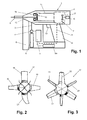
- the line 3 connects a metering device 4 with the combustion chamber 2, wherein the metering device 4 in turn is connected to the fuel tank 5 arranged in or on the housing 1.
- the fuel tank can be designed in particular as a replaceable cartridge.
- the tacker additionally comprises an electronic control 6 with an electric accumulator 6a as an energy store.
- a spark plug 7 is driven in the combustion chamber 2 by means of a line 7a.
- the metering device 4 is actuated, provided that it has electrical valves or other electrically controlled components.
- a magazine 8 for storing fasteners, such as nails is arranged in a front portion of the tacker.
- a pressing member 9 can be pressed against a workpiece to release a triggering of the tacker.
- An inventive tacker is characterized by a fan optimized in its shape.
- Fig. 2 shows a fan with four different, inventively shaped sheets 18, 19, 20, 21, each with the same shape of the hub. It should be understood that this serves to illustrate four different embodiments.
- the upper sheet 18 has a nearly rectangular shape. Almost over the entire blade length is a constant width in axial projection (axial plan view as in Fig. 2 ) in front.
- the right blade 19 has a trapezoidal shape in which the projected width tapers radially outward. The slope is constant, so that the leaf edges are straight.
- the left sheet 20 is similar in shape to sheet 19, but has concavely curved sheet edges. Alternatively or additionally, convexly curved leaf edges are also possible.
- the lower blade 21 runs relatively acute. In addition, it has a curved in the circumferential direction like a blade.
- Fig. 3 shown example of a fan according to the invention are two alternately arranged type of leaves 22, 23 with different shapes before. Both types of sheets 22, 23 meet in the present case in each case the criteria of a radially outwardly decreasing width.
- Fig. 4 illustrates an example of the invention in which the angle of attack of a blade 24 increases from the outside radially inward to a hub region 25.
- the drawn, radially inner angle of attack B is thus greater than the radially outer angle of attack A.
- leaves 26, 27, 28 is in a radially outer end portion of the sheet in each case an angled in the axial direction end portion 29 before. Through this End section is achieved effective turbulence generation in large space depth even at low speeds.
- the example according to Fig. 6 shows a fan according to the invention in axial plan view and in lateral plan view.
- the fan has an odd number of leaves 30, in this case five.
- Each of the leaves is equally shaped and has a local maximum 31 of its width, the maximum being roughly estimated at half of a maximum radius from the axis of rotation.
- the fan has an even number of sheets, for example 4, 6 or 8 sheets.
- the maximum is strongly limited locally so that, in an axial plan view, it is shaped similar to a nose protruding in front of the blade edge.
- the local maximum exists only on one side of the sheet, while the other sheet edge is substantially straight.
Landscapes
- Engineering & Computer Science (AREA)
- Chemical & Material Sciences (AREA)
- Combustion & Propulsion (AREA)
- Mechanical Engineering (AREA)
- Portable Nailing Machines And Staplers (AREA)
- Structures Of Non-Positive Displacement Pumps (AREA)
Abstract
Description
- Die Erfindung betrifft ein Eintreibgerät, insbesondere ein handgeführtes Eintreibgerät, nach dem Oberbegriff des Anspruchs 1.
-
EP 1 555 090 A1 beschreibt ein gasbetriebenes Eintreibgerät mit einer Brennkammer, einem in einem Zylinder geführten Kolben sowie einem elektrisch angetriebenen Ventilator zur Verwirbelung eines Gasgemisches in der Brennkammer. Es werden Maßnahmen zur Erzeugung von Turbulenzen vorgeschlagen, die in der Ausbildung von axial vorstehenden Strukturen im Bereich der Rotorblätter bestehen. - Es ist die Aufgabe der Erfindung, ein Eintreibgerät anzugeben, das eine schnelle Zündfähigkeit durch einen optimierten Ventilator bereitstellt.
- Diese Aufgabe wird für ein eingangs genanntes Eintreibgerät erfindungsgemäß mit den kennzeichnenden Merkmalen des Anspruchs 1 gelöst. Durch die vorgeschlagenen Maßnahmen des sich nicht nach außen hin verbreiternden Blattabschnitts wird ein Ventilator gewählt, der ein relativ geringes Trägheitsmoment hat bzw. bei gegebenen Leistung schnell auf eine Nutzdrehzahl gebracht werden kann. Durch die nach innen ansteigende Blattverwindung des Abschnitts wird alternativ oder ergänzend eine Geometrie gewählt, die eine besonders gute Verwirbelung mit einfachen Mitteln ermöglicht.
- Besonders bevorzugt werden beide Maßnahmen gleichzeitig realisiert, wobei die jeweiligen Abschnitte des Blattes identisch sein können, aber nicht müssen.
- In dem Übergangsbereich zur der Nabe des Ventilator kann die Blattanstellung dann bevorzugt wieder zurückgehen, zum Beispiel bis auf Null.
- Bei einer bevorzugten Weiterbildung der Erfindung nimmt die projizierte Breite über den Verlauf des Abschnitts radial nach außen ab, insbesondere um wenigstens ein Zehntel über die Länge des Abschnitts. Hierdurch wird ein Ventilator mit besonders geringem Trägheitsmoment gewählt.
- Bei einer weiteren, in bezüglich einer Turbulenzerzeugung optimierten Detailgestaltung beträgt die Zunahme des Anstellwinkels über den Abschnitt wenigstens ein Zehntel, insbesondere wenigstens ein Fünftel, eines maximalen Anstellwinkels des Abschnitts.
- Bei einem erfindungsgemäßen Ventilator kann bevorzugt wenigstens ein erstes Blatt mit einer ersten Formgebung und wenigstens ein zweites Blatt mit einer zweiten Formgebung, die von der ersten Formgebung verschieden ist, angeordnet sein. Die Kombination verschiedener Blattgeometrien begünstigt die Entstehung von Turbulenzen durch die Brechung von Symmetrien, wobei zugleich ein geringes Trägheitsmoment ermöglicht wird.
- Bei einer allgemein vorteilhaften Weiterbildung der Erfindung hat zumindest eines der Blätter einen radial äußeren Endabschnitt, wobei der Endabschnitt gegenüber dem übrigen Blatt in axialer Richtung abgewinkelt ist, bevorzugt um wenigstens zehn Grad. Ein solcher abgewinkelter Abschnitt erzeugt bereits bei geringen Drehzahlen hohe Turbulenzen in großer Raumtiefe. Dabei kann der Endabschnitt zur weiteren Verbesserung der Turbulenzen in sich gedreht sein.
- Bei einer weiteren bevorzugten Ausführungsform ist es zur Optimierung der Verwirbelung vorgesehen, dass zumindest eines der Blätter, bevorzugt sämtliche Blätter, einen in der Umfangsrichtung säbelartig gekrümmten Verlauf aufweist.
- Eine weitere erfindungsgemäße Formgebung eines Ventilators sieht vor, dass zumindest eines der Blätter ein lokales Maximum der projizierten Breite aufweist.
- Weitere Merkmale und Vorteile der Erfindung ergeben sich aus den Ausführungsbeispielen sowie aus den abhängigen Ansprüchen. Nachfolgend werden mehrere bevorzugte Ausführungsbeispiele der Erfindung beschrieben und anhand der anliegenden Zeichnungen näher erläutert.
- Fig. 1
- zeigt eine schematische Darstellung eines erfindungsgemäßen Eintreibgerätes.
- Fig. 2
- zeigt eine schematische Ansicht von vier verschiedenen, jeweils erfindungsgemäßen Blattformen eines Ventilators des Eintreibgerätes aus
Fig. 1 . - Fig. 3
- zeigt einen weiteren, erfindungsgemäßen Ventilator mit zwei verschiedenen Formgebungen der Blätter.
- Fig. 4
- zeigt ein Blatt eines weiteren, erfindungsgemäßen Ventilators.
- Fig. 5
- zeigt drei Abwandlungen von Blättern eines erfindungsgemäßen Ventilators mit abgewinkelten Endbereichen.
- Fig. 6
- zeigt einen weiteren, erfindungsgemäßen Ventilator, dessen Blätter ein lokales Maximum einer Blattbreite aufweisen.
- Das in
Fig. 1 schematisch gezeigte Eintreibgerät umfasst ein Gehäuse 1, in dem eine Brennkammer 2 angeordnet ist. Flüssiggas ist als Brennstoff in einem Brennstofftank 5 gespeichert und kann über eine Leitung 3 in die Brennkammer 2 eingespritzt werden. Die Leitung 3 verbindet eine Dosiervorrichtung 4 mit der Brennkammer 2, wobei die Dosiervorrichtung 4 ihrerseits mit dem in oder an dem Gehäuse 1 angeordneten Brennstofftank 5 verbunden ist. Der Brennstofftank kann insbesondere als auswechselbare Kartusche ausgebildet sein. - Das Eintreibgerät umfasst zudem eine elektronische Steuerung 6 mit einem elektrischen Akkumulator 6a als Energiespeicher. Über die elektronische Steuerung 6 wird eine Zündkerze 7 in der Brennkammer 2 mittels einer Leitung 7a angesteuert. Weiterhin wird gegebenenfalls die Dosiervorrichtung 4 angesteuert, sofern diese über elektrische Ventile oder andere elektrisch gesteuerte Komponenten verfügt. In einem vorderen Bereich des Eintreibgeräts ist ein Magazin 8 zur Speicherung von Befestigungsmitteln, wie zum Beispiel Nägeln, angeordnet. Ein Anpressglied 9 kann gegen ein Werkstück gedrückt werden, um ein Auslösen des Eintreibgeräts freizugeben.
- Das Eintreiben eines Befestigungsglieds aus dem Magazin 8 erfolgt über die Zündung eines Flüssiggas-Luft-Gemisches in der Brennkammer 2 mittels der Zündkerze 7, wonach ein Kolben 10 in einem Zylinder 11 laufend nach vorne getrieben wird und über einen Eintreibstößel 12 das Befestigungsglied bzw. den Nagel in das Werkstück eintreibt. Dieser Eintreibvorgang wird von einer Bedienperson über einen Schalter 13 ausgelöst, der vorliegend in einem Griffbereich 14 des Gehäuses 1 angeordnet ist. Der Weg des Kolbens 10 wird von einem elastischen Anschlag oder Puffer 15 begrenzt. Vor einer Zündung wird das Gemisch auf bekannte Weise mit Unterstützung eines über einen elektrischen Motor 16 angetriebenen Ventilators 17 in der Brennkammer verteilt. Der Ventilator 17 kann zudem nach der Verbrennung dazu beitragen, die Abgase aus der Brennkammer auszuspülen oder die Brennkammer beziehungsweise das Eintreibgerät zu kühlen.
- Ein erfindungsgemäßes Eintreibgerät zeichnet sich durch einen in seiner Formgebung optimierten Ventilator aus.
-
Fig. 2 zeigt einen Ventilator mit vier jeweils verschiedenen, erfindungsgemäß geformten Blättern 18, 19, 20, 21 bei jeweils gleicher Formgebung der Nabe. Es versteht sich, dass dies der Veranschaulichung von vier verschiedenen Ausführungsbeispielen dient. - Das Obere Blatt 18 hat eine nahezu rechteckige Form. Nahezu über der gesamten Blattlänge liegt eine konstante Breite in axialer Projektion (axiale Draufsicht wie in
Fig. 2 ) vor. - Das rechte Blatt 19 hat eine Trapezform, bei der sich die projizierte Breite radial nach außen verjüngt. Die Steigung ist dabei konstant, so dass die Blattkanten gerade verlaufen.
- Das linke Blatt 20 zeigt eine ähnliche Form wie Blatt 19, hat aber konkav gebogene Blattkanten. Alternativ oder ergänzend sind auch konvex gebogene Blattkanten möglich.
- Das untere Blatt 21 läuft relativ spitz zu. Zudem hat es einen in Umfangsrichtung säbelartig gekrümmten Verlauf.
- Bei dem in
Fig. 3 gezeigten Beispiel eines erfindungsgemäßen Ventilators liegen zwei im Wechsel angeordnete Art von Blättern 22, 23 mit unterschiedlichen Formgebungen vor. Beide Blattarten 22, 23 erfüllen im vorliegenden Fall jeweils die Kriterien einer radial nach außen abnehmenden Breite. -
Fig. 4 illustriert ein Beispiel der Erfindung, bei dem der Anstellwinkel eines Blattes 24 sich von außen radial nach innen bis zu einem Nabenbereich 25 vergrößert. Der eingezeichnete, radial innere Anstellwinkel B ist somit größer als der radial äußere Anstellwinkel A. - Bei den in
Fig. 5 gezeigten Blättern 26, 27, 28 liegt in einem radial äußeren Endbereich des Blattes jeweils ein in axialer Richtung abgewinkelter Endabschnitt 29 vor. Durch diesen Endabschnitt wird eine effektive Turbulenzerzeugung in großer Raumtiefe bereits bei niedrigen Drehzahlen erzielt. - Das Beispiel gemäß
Fig. 6 zeigt einen erfindungsgemäßen Ventilator in axialer Draufsicht sowie in seitlicher Draufsicht. Der Ventilator hat eine ungerade Anzahl von Blättern 30, vorliegend fünf. Jedes Der Blätter ist gleich geformt und hat ein lokales Maximum 31 seiner Breite, wobei das Maximum sich grob geschätzt auf der Hälfte eines maximalen Radius ausgehend von der Drehachse befindet. Bei einem nicht gezeigten Ausführungsbeispiel hat der Ventilator eine gerade Anzahl von Blättern, beispielsweise 4, 6 oder 8 Blätter. - Das Maximum ist vorliegend lokal stark begrenzt so dass es in axialer Draufsicht ähnlich einer vor die Blattkante vorspringenden Nase geformt ist. Das lokale Maximum liegt nur auf einer Seite des Blattes vor, während die andere Blattkante im Wesentlichen gerade verläuft.
- Es versteht sich, dass die einzelnen Merkmale der verschiedenen Ausführungsbeispiele je nach Anforderungen sinnvoll miteinander kombiniert werden können.
Claims (8)
- Eintreibgerät, umfassend
einen Tank (5) zur Speicherung eines Brennstoffs, insbesondere Flüssiggas,
eine mit dem Tank (5) verbundene Brennkammer (2),
einen beweglichen Kolben (10) zum Antrieb eines Eintreibstößels (12), und
einen auf die Brennkammer wirkenden, um eine Achse rotierbaren Ventilator mit mehreren radial zu der Achse erstreckten Blättern,
dadurch gekennzeichnet,
dass wenigstens eines der folgenden Merkmale erfüllt ist:- zumindest eines der Blätter (18, 19, 20, 21, 22, 23, 26, 28, 30) hat einen Abschnitt von zumindest einem Drittel, insbesondere zumindest der Hälfte, einer radialen Länge des Blatts, dessen in axialer Richtung projizierte Breite radial nach außen nicht zunimmt, und/oder- zumindest eines der Blätter (24, 28) hat einen Abschnitt von zumindest einem Drittel, insbesondere zumindest der Hälfte, einer radialen Länge des Blatts, dessen Anstellwinkel (A, B) um eine Blattachse sich von außen nach innen vergrößert, insbesondere bis zu einem Übergangsbereich zu einer Nabe des Ventilators. - Eintreibgerät nach Anspruch 1, dadurch gekennzeichnet, dass die projizierte Breite über den Verlauf des Abschnitts radial nach außen abnimmt, insbesondere um wenigstens ein Zehntel über die Länge des Abschnitts.
- Eintreibgerät nach einem der vorhergehenden Ansprüche, dadurch gekennzeichnet, dass die Zunahme des Anstellwinkels (A, B) über den Abschnitt wenigstens ein Zehntel, insbesondere wenigstens ein Fünftel, eines maximalen Anstellwinkels des Abschnitts beträgt.
- Eintreibgerät nach einem der vorhergehenden Ansprüche, dadurch gekennzeichnet, dass an dem Ventilator wenigstens ein erstes Blatt (22) mit einer ersten Formgebung und wenigstens ein zweites Blatt (23) mit einer zweiten Formgebung, die von der ersten Formgebung verschieden ist, angeordnet ist.
- Eintreibgerät nach einem der vorhergehenden Ansprüche, dadurch gekennzeichnet, dass zumindest eines der Blätter (26, 27, 28) einen radial äußeren Endabschnitt (29) aufweist, wobei der Endabschnitt (29) gegenüber dem übrigen Blatt in axialer Richtung abgewinkelt ist, insbesondere um wenigstens zehn Grad.
- Eintreibgerät nach Anspruch 5, dadurch gekennzeichnet, dass der Endabschnitt (29) in sich gedreht ist.
- Eintreibgerät nach einem der vorhergehenden Ansprüche, dadurch gekennzeichnet, dass zumindest eines der Blätter (21), insbesondere sämtliche Blätter, einen in der Umfangsrichtung säbelartig gekrümmten Verlauf aufweist.
- Eintreibgerät nach einem der vorhergehenden Ansprüche, dadurch gekennzeichnet, dass zumindest eines der Blätter (30) ein lokales Maximum (31) der projizierten Breite aufweist.
Applications Claiming Priority (1)
| Application Number | Priority Date | Filing Date | Title |
|---|---|---|---|
| DE201210206116 DE102012206116A1 (de) | 2012-04-13 | 2012-04-13 | Eintreibgerät |
Publications (3)
| Publication Number | Publication Date |
|---|---|
| EP2650086A2 true EP2650086A2 (de) | 2013-10-16 |
| EP2650086A3 EP2650086A3 (de) | 2015-04-01 |
| EP2650086B1 EP2650086B1 (de) | 2017-02-01 |
Family
ID=48049873
Family Applications (1)
| Application Number | Title | Priority Date | Filing Date |
|---|---|---|---|
| EP13162838.0A Active EP2650086B1 (de) | 2012-04-13 | 2013-04-09 | Eintreibgerät |
Country Status (3)
| Country | Link |
|---|---|
| US (1) | US20130270320A1 (de) |
| EP (1) | EP2650086B1 (de) |
| DE (1) | DE102012206116A1 (de) |
Citations (1)
| Publication number | Priority date | Publication date | Assignee | Title |
|---|---|---|---|---|
| EP1555090A1 (de) | 2004-01-16 | 2005-07-20 | Hitachi Koki Co., Ltd. | Kraftwerkzeug mit interner Verbrennung und Ventilator |
Family Cites Families (23)
| Publication number | Priority date | Publication date | Assignee | Title |
|---|---|---|---|---|
| US1463556A (en) * | 1920-05-26 | 1923-07-31 | Reed Sylvanus Albert | Aeronautical propeller |
| DE600534C (de) * | 1928-03-31 | 1934-07-25 | Guiseppe Massera | Schrauben- oder Fluegelventilator |
| DE679517C (de) * | 1932-07-08 | 1939-08-08 | Paul Havard | Fluegel fuer Schraubenradluefter oder -geblaese |
| US2127628A (en) * | 1938-01-22 | 1938-08-23 | Hauser Henry | Fuel mixer |
| US2238749A (en) * | 1939-01-30 | 1941-04-15 | Clarence B Swift | Fan blade |
| US2415668A (en) * | 1945-04-09 | 1947-02-11 | Barabino Alfred | Turbo gas saver |
| GB848278A (en) * | 1957-04-16 | 1960-09-14 | Enso Gutzeit Oy | Improvements in or relating to impellers |
| FI55784C (fi) * | 1976-07-30 | 1979-10-10 | Eero Mikael Kivimaa | Kutterhuvud |
| IN157475B (de) * | 1981-01-22 | 1986-04-05 | Signode Corp | |
| US4483474A (en) * | 1981-01-22 | 1984-11-20 | Signode Corporation | Combustion gas-powered fastener driving tool |
| KR890001581Y1 (ko) * | 1986-07-21 | 1989-04-06 | 삼성전자주식회사 | 전자렌지의 고주파분산팬 보조날개 취부장치 |
| US5215441A (en) * | 1991-11-07 | 1993-06-01 | Carrier Corporation | Air conditioner with condensate slinging fan |
| US5197646A (en) * | 1992-03-09 | 1993-03-30 | Illinois Tool Works Inc. | Combustion-powered tool assembly |
| US5730583A (en) * | 1994-09-29 | 1998-03-24 | Valeo Thermique Moteur | Axial flow fan blade structure |
| US7210910B1 (en) * | 1998-04-07 | 2007-05-01 | Research Foundation Of The University Of Central Florida, Inc. | Enhancements to high efficiency ceiling fan |
| US6659721B1 (en) * | 1998-04-07 | 2003-12-09 | University Of Central Florida | High efficiency ceiling fan blades |
| JP3047292B1 (ja) * | 1998-11-24 | 2000-05-29 | セイコー精機株式会社 | ターボ分子ポンプ及び真空装置 |
| US6619527B1 (en) * | 2000-10-10 | 2003-09-16 | Illinois Tool Works Inc. | Combustion powered tool suspension for iron core fan motor |
| JP4161015B2 (ja) * | 2002-02-15 | 2008-10-08 | 臼井国際産業株式会社 | 軸流ファン |
| US6863045B2 (en) * | 2003-05-23 | 2005-03-08 | Illinois Tool Works Inc. | Combustion apparatus having improved airflow |
| JP4650779B2 (ja) * | 2004-04-09 | 2011-03-16 | 日立工機株式会社 | 燃焼式動力工具 |
| TW201034808A (en) * | 2009-03-20 | 2010-10-01 | Basso Ind Corp | Motor vibration-absorbing device of gas gun |
| JP5626814B2 (ja) * | 2009-08-21 | 2014-11-19 | ダス・ヴェルク・ピーティーワイ・リミテッドDas Werk Pty Ltd | ローターカップリング |
-
2012
- 2012-04-13 DE DE201210206116 patent/DE102012206116A1/de not_active Withdrawn
-
2013
- 2013-04-09 EP EP13162838.0A patent/EP2650086B1/de active Active
- 2013-04-11 US US13/860,588 patent/US20130270320A1/en not_active Abandoned
Patent Citations (1)
| Publication number | Priority date | Publication date | Assignee | Title |
|---|---|---|---|---|
| EP1555090A1 (de) | 2004-01-16 | 2005-07-20 | Hitachi Koki Co., Ltd. | Kraftwerkzeug mit interner Verbrennung und Ventilator |
Also Published As
| Publication number | Publication date |
|---|---|
| EP2650086A3 (de) | 2015-04-01 |
| EP2650086B1 (de) | 2017-02-01 |
| US20130270320A1 (en) | 2013-10-17 |
| DE102012206116A1 (de) | 2013-10-17 |
Similar Documents
| Publication | Publication Date | Title |
|---|---|---|
| DE112013001960B4 (de) | Eintreibwerkzeug | |
| DE19833943C2 (de) | Schlagschrauber | |
| DE3012501C2 (de) | Vorrichtung zur vorübergehenden Verriegelung eines Trägheitsschwungrades | |
| DE102015212381B4 (de) | Abgasturbolader mit einer Wastegate-Einrichtung | |
| DE112009001141T5 (de) | Antriebsanordnung für ein Kraftwerkzeug | |
| DE112020006383T5 (de) | Drehendes Werkzeug | |
| DE112018003406T5 (de) | Ratschenschlüssel | |
| DE8031519U1 (de) | Schlagwerkzeug | |
| DE202017106955U1 (de) | Kraftwerkzeug | |
| DE202015007915U1 (de) | Schlagwerkzeug | |
| EP2650086B1 (de) | Eintreibgerät | |
| DE102015121463A1 (de) | Verdichteranordnung für einen Verbrennungsmotor sowie Verbrennungsmotor | |
| DE102017128856A1 (de) | Elektromotor | |
| DE202012100512U1 (de) | Aus wenigstens drei Teilen bestehendes Luftpumpensystem | |
| EP2406801B1 (de) | Elektrischer schalter | |
| DE102012007194A1 (de) | Verfahren zum Betreiben eines Nietsetzgeräts | |
| EP3541576A1 (de) | Schwungradangetriebenes setzgerät | |
| AT512369B1 (de) | Rotationskolbenmaschine | |
| DE486737C (de) | Brennkraftmaschinen-Anlage, besonders zur Erzeugung von elektrischem Strom, mit zum Aufladen oder Spuelen dienendem Abgas-Kreiselgeblaese | |
| EP4313492B1 (de) | Pyrotechnisches eintreibgerät | |
| EP3083153B1 (de) | Eintreibgerät | |
| EP4313491B1 (de) | Pyrotechnisches eintreibgerät | |
| DE102024118462A1 (de) | Antriebsbaugruppe für ein elektrowerkzeug | |
| DE2136205A1 (de) | Einspritzdüse für Verbrennungsmotoren | |
| DE202024103268U1 (de) | Robustes Heftgerät mit geringem Kraftaufwand |
Legal Events
| Date | Code | Title | Description |
|---|---|---|---|
| PUAI | Public reference made under article 153(3) epc to a published international application that has entered the european phase |
Free format text: ORIGINAL CODE: 0009012 |
|
| AK | Designated contracting states |
Kind code of ref document: A2 Designated state(s): AL AT BE BG CH CY CZ DE DK EE ES FI FR GB GR HR HU IE IS IT LI LT LU LV MC MK MT NL NO PL PT RO RS SE SI SK SM TR |
|
| AX | Request for extension of the european patent |
Extension state: BA ME |
|
| RIN1 | Information on inventor provided before grant (corrected) |
Inventor name: SPERRFECHTER, THOMAS Inventor name: BRUGGMUELLER, PETER |
|
| PUAL | Search report despatched |
Free format text: ORIGINAL CODE: 0009013 |
|
| AK | Designated contracting states |
Kind code of ref document: A3 Designated state(s): AL AT BE BG CH CY CZ DE DK EE ES FI FR GB GR HR HU IE IS IT LI LT LU LV MC MK MT NL NO PL PT RO RS SE SI SK SM TR |
|
| AX | Request for extension of the european patent |
Extension state: BA ME |
|
| RIC1 | Information provided on ipc code assigned before grant |
Ipc: B25C 1/08 20060101AFI20150226BHEP |
|
| 17P | Request for examination filed |
Effective date: 20151001 |
|
| RBV | Designated contracting states (corrected) |
Designated state(s): AL AT BE BG CH CY CZ DE DK EE ES FI FR GB GR HR HU IE IS IT LI LT LU LV MC MK MT NL NO PL PT RO RS SE SI SK SM TR |
|
| GRAP | Despatch of communication of intention to grant a patent |
Free format text: ORIGINAL CODE: EPIDOSNIGR1 |
|
| INTG | Intention to grant announced |
Effective date: 20161021 |
|
| GRAS | Grant fee paid |
Free format text: ORIGINAL CODE: EPIDOSNIGR3 |
|
| GRAA | (expected) grant |
Free format text: ORIGINAL CODE: 0009210 |
|
| AK | Designated contracting states |
Kind code of ref document: B1 Designated state(s): AL AT BE BG CH CY CZ DE DK EE ES FI FR GB GR HR HU IE IS IT LI LT LU LV MC MK MT NL NO PL PT RO RS SE SI SK SM TR |
|
| REG | Reference to a national code |
Ref country code: GB Ref legal event code: FG4D Free format text: NOT ENGLISH |
|
| REG | Reference to a national code |
Ref country code: CH Ref legal event code: EP Ref country code: AT Ref legal event code: REF Ref document number: 865150 Country of ref document: AT Kind code of ref document: T Effective date: 20170215 |
|
| REG | Reference to a national code |
Ref country code: IE Ref legal event code: FG4D Free format text: LANGUAGE OF EP DOCUMENT: GERMAN |
|
| REG | Reference to a national code |
Ref country code: DE Ref legal event code: R096 Ref document number: 502013006208 Country of ref document: DE |
|
| REG | Reference to a national code |
Ref country code: FR Ref legal event code: PLFP Year of fee payment: 5 |
|
| REG | Reference to a national code |
Ref country code: NL Ref legal event code: MP Effective date: 20170201 |
|
| REG | Reference to a national code |
Ref country code: LT Ref legal event code: MG4D |
|
| PG25 | Lapsed in a contracting state [announced via postgrant information from national office to epo] |
Ref country code: HR Free format text: LAPSE BECAUSE OF FAILURE TO SUBMIT A TRANSLATION OF THE DESCRIPTION OR TO PAY THE FEE WITHIN THE PRESCRIBED TIME-LIMIT Effective date: 20170201 Ref country code: LT Free format text: LAPSE BECAUSE OF FAILURE TO SUBMIT A TRANSLATION OF THE DESCRIPTION OR TO PAY THE FEE WITHIN THE PRESCRIBED TIME-LIMIT Effective date: 20170201 Ref country code: NO Free format text: LAPSE BECAUSE OF FAILURE TO SUBMIT A TRANSLATION OF THE DESCRIPTION OR TO PAY THE FEE WITHIN THE PRESCRIBED TIME-LIMIT Effective date: 20170501 Ref country code: FI Free format text: LAPSE BECAUSE OF FAILURE TO SUBMIT A TRANSLATION OF THE DESCRIPTION OR TO PAY THE FEE WITHIN THE PRESCRIBED TIME-LIMIT Effective date: 20170201 Ref country code: IS Free format text: LAPSE BECAUSE OF FAILURE TO SUBMIT A TRANSLATION OF THE DESCRIPTION OR TO PAY THE FEE WITHIN THE PRESCRIBED TIME-LIMIT Effective date: 20170601 Ref country code: GR Free format text: LAPSE BECAUSE OF FAILURE TO SUBMIT A TRANSLATION OF THE DESCRIPTION OR TO PAY THE FEE WITHIN THE PRESCRIBED TIME-LIMIT Effective date: 20170502 |
|
| PG25 | Lapsed in a contracting state [announced via postgrant information from national office to epo] |
Ref country code: RS Free format text: LAPSE BECAUSE OF FAILURE TO SUBMIT A TRANSLATION OF THE DESCRIPTION OR TO PAY THE FEE WITHIN THE PRESCRIBED TIME-LIMIT Effective date: 20170201 Ref country code: ES Free format text: LAPSE BECAUSE OF FAILURE TO SUBMIT A TRANSLATION OF THE DESCRIPTION OR TO PAY THE FEE WITHIN THE PRESCRIBED TIME-LIMIT Effective date: 20170201 Ref country code: BG Free format text: LAPSE BECAUSE OF FAILURE TO SUBMIT A TRANSLATION OF THE DESCRIPTION OR TO PAY THE FEE WITHIN THE PRESCRIBED TIME-LIMIT Effective date: 20170501 Ref country code: NL Free format text: LAPSE BECAUSE OF FAILURE TO SUBMIT A TRANSLATION OF THE DESCRIPTION OR TO PAY THE FEE WITHIN THE PRESCRIBED TIME-LIMIT Effective date: 20170201 Ref country code: SE Free format text: LAPSE BECAUSE OF FAILURE TO SUBMIT A TRANSLATION OF THE DESCRIPTION OR TO PAY THE FEE WITHIN THE PRESCRIBED TIME-LIMIT Effective date: 20170201 Ref country code: PT Free format text: LAPSE BECAUSE OF FAILURE TO SUBMIT A TRANSLATION OF THE DESCRIPTION OR TO PAY THE FEE WITHIN THE PRESCRIBED TIME-LIMIT Effective date: 20170601 Ref country code: LV Free format text: LAPSE BECAUSE OF FAILURE TO SUBMIT A TRANSLATION OF THE DESCRIPTION OR TO PAY THE FEE WITHIN THE PRESCRIBED TIME-LIMIT Effective date: 20170201 Ref country code: PL Free format text: LAPSE BECAUSE OF FAILURE TO SUBMIT A TRANSLATION OF THE DESCRIPTION OR TO PAY THE FEE WITHIN THE PRESCRIBED TIME-LIMIT Effective date: 20170201 |
|
| PG25 | Lapsed in a contracting state [announced via postgrant information from national office to epo] |
Ref country code: EE Free format text: LAPSE BECAUSE OF FAILURE TO SUBMIT A TRANSLATION OF THE DESCRIPTION OR TO PAY THE FEE WITHIN THE PRESCRIBED TIME-LIMIT Effective date: 20170201 Ref country code: IT Free format text: LAPSE BECAUSE OF FAILURE TO SUBMIT A TRANSLATION OF THE DESCRIPTION OR TO PAY THE FEE WITHIN THE PRESCRIBED TIME-LIMIT Effective date: 20170201 Ref country code: CZ Free format text: LAPSE BECAUSE OF FAILURE TO SUBMIT A TRANSLATION OF THE DESCRIPTION OR TO PAY THE FEE WITHIN THE PRESCRIBED TIME-LIMIT Effective date: 20170201 Ref country code: SK Free format text: LAPSE BECAUSE OF FAILURE TO SUBMIT A TRANSLATION OF THE DESCRIPTION OR TO PAY THE FEE WITHIN THE PRESCRIBED TIME-LIMIT Effective date: 20170201 Ref country code: RO Free format text: LAPSE BECAUSE OF FAILURE TO SUBMIT A TRANSLATION OF THE DESCRIPTION OR TO PAY THE FEE WITHIN THE PRESCRIBED TIME-LIMIT Effective date: 20170201 |
|
| REG | Reference to a national code |
Ref country code: DE Ref legal event code: R097 Ref document number: 502013006208 Country of ref document: DE |
|
| PG25 | Lapsed in a contracting state [announced via postgrant information from national office to epo] |
Ref country code: SM Free format text: LAPSE BECAUSE OF FAILURE TO SUBMIT A TRANSLATION OF THE DESCRIPTION OR TO PAY THE FEE WITHIN THE PRESCRIBED TIME-LIMIT Effective date: 20170201 Ref country code: DK Free format text: LAPSE BECAUSE OF FAILURE TO SUBMIT A TRANSLATION OF THE DESCRIPTION OR TO PAY THE FEE WITHIN THE PRESCRIBED TIME-LIMIT Effective date: 20170201 |
|
| REG | Reference to a national code |
Ref country code: CH Ref legal event code: PL |
|
| PLBE | No opposition filed within time limit |
Free format text: ORIGINAL CODE: 0009261 |
|
| STAA | Information on the status of an ep patent application or granted ep patent |
Free format text: STATUS: NO OPPOSITION FILED WITHIN TIME LIMIT |
|
| 26N | No opposition filed |
Effective date: 20171103 |
|
| REG | Reference to a national code |
Ref country code: IE Ref legal event code: MM4A |
|
| PG25 | Lapsed in a contracting state [announced via postgrant information from national office to epo] |
Ref country code: MC Free format text: LAPSE BECAUSE OF FAILURE TO SUBMIT A TRANSLATION OF THE DESCRIPTION OR TO PAY THE FEE WITHIN THE PRESCRIBED TIME-LIMIT Effective date: 20170201 |
|
| PG25 | Lapsed in a contracting state [announced via postgrant information from national office to epo] |
Ref country code: LI Free format text: LAPSE BECAUSE OF NON-PAYMENT OF DUE FEES Effective date: 20170430 Ref country code: LU Free format text: LAPSE BECAUSE OF NON-PAYMENT OF DUE FEES Effective date: 20170409 Ref country code: SI Free format text: LAPSE BECAUSE OF FAILURE TO SUBMIT A TRANSLATION OF THE DESCRIPTION OR TO PAY THE FEE WITHIN THE PRESCRIBED TIME-LIMIT Effective date: 20170201 Ref country code: CH Free format text: LAPSE BECAUSE OF NON-PAYMENT OF DUE FEES Effective date: 20170430 |
|
| REG | Reference to a national code |
Ref country code: BE Ref legal event code: MM Effective date: 20170430 |
|
| REG | Reference to a national code |
Ref country code: FR Ref legal event code: PLFP Year of fee payment: 6 |
|
| PG25 | Lapsed in a contracting state [announced via postgrant information from national office to epo] |
Ref country code: IE Free format text: LAPSE BECAUSE OF NON-PAYMENT OF DUE FEES Effective date: 20170409 |
|
| PG25 | Lapsed in a contracting state [announced via postgrant information from national office to epo] |
Ref country code: BE Free format text: LAPSE BECAUSE OF NON-PAYMENT OF DUE FEES Effective date: 20170430 |
|
| PG25 | Lapsed in a contracting state [announced via postgrant information from national office to epo] |
Ref country code: MT Free format text: LAPSE BECAUSE OF FAILURE TO SUBMIT A TRANSLATION OF THE DESCRIPTION OR TO PAY THE FEE WITHIN THE PRESCRIBED TIME-LIMIT Effective date: 20170201 |
|
| REG | Reference to a national code |
Ref country code: AT Ref legal event code: MM01 Ref document number: 865150 Country of ref document: AT Kind code of ref document: T Effective date: 20180409 |
|
| PG25 | Lapsed in a contracting state [announced via postgrant information from national office to epo] |
Ref country code: HU Free format text: LAPSE BECAUSE OF FAILURE TO SUBMIT A TRANSLATION OF THE DESCRIPTION OR TO PAY THE FEE WITHIN THE PRESCRIBED TIME-LIMIT; INVALID AB INITIO Effective date: 20130409 |
|
| PG25 | Lapsed in a contracting state [announced via postgrant information from national office to epo] |
Ref country code: AT Free format text: LAPSE BECAUSE OF NON-PAYMENT OF DUE FEES Effective date: 20180409 Ref country code: CY Free format text: LAPSE BECAUSE OF NON-PAYMENT OF DUE FEES Effective date: 20170201 |
|
| PG25 | Lapsed in a contracting state [announced via postgrant information from national office to epo] |
Ref country code: MK Free format text: LAPSE BECAUSE OF FAILURE TO SUBMIT A TRANSLATION OF THE DESCRIPTION OR TO PAY THE FEE WITHIN THE PRESCRIBED TIME-LIMIT Effective date: 20170201 |
|
| PG25 | Lapsed in a contracting state [announced via postgrant information from national office to epo] |
Ref country code: TR Free format text: LAPSE BECAUSE OF FAILURE TO SUBMIT A TRANSLATION OF THE DESCRIPTION OR TO PAY THE FEE WITHIN THE PRESCRIBED TIME-LIMIT Effective date: 20170201 |
|
| PG25 | Lapsed in a contracting state [announced via postgrant information from national office to epo] |
Ref country code: AL Free format text: LAPSE BECAUSE OF FAILURE TO SUBMIT A TRANSLATION OF THE DESCRIPTION OR TO PAY THE FEE WITHIN THE PRESCRIBED TIME-LIMIT Effective date: 20170201 |
|
| PGFP | Annual fee paid to national office [announced via postgrant information from national office to epo] |
Ref country code: DE Payment date: 20250422 Year of fee payment: 13 |
|
| PGFP | Annual fee paid to national office [announced via postgrant information from national office to epo] |
Ref country code: GB Payment date: 20250423 Year of fee payment: 13 |
|
| PGFP | Annual fee paid to national office [announced via postgrant information from national office to epo] |
Ref country code: FR Payment date: 20250425 Year of fee payment: 13 |