EP2649631B1 - Thermische abtrennvorrichtung - Google Patents
Thermische abtrennvorrichtung Download PDFInfo
- Publication number
- EP2649631B1 EP2649631B1 EP11807649.6A EP11807649A EP2649631B1 EP 2649631 B1 EP2649631 B1 EP 2649631B1 EP 11807649 A EP11807649 A EP 11807649A EP 2649631 B1 EP2649631 B1 EP 2649631B1
- Authority
- EP
- European Patent Office
- Prior art keywords
- conductor
- conductor portion
- insulating body
- section
- contact point
- Prior art date
- Legal status (The legal status is an assumption and is not a legal conclusion. Google has not performed a legal analysis and makes no representation as to the accuracy of the status listed.)
- Active
Links
Images

Classifications
-
- H—ELECTRICITY
- H01—ELECTRIC ELEMENTS
- H01C—RESISTORS
- H01C7/00—Non-adjustable resistors formed as one or more layers or coatings; Non-adjustable resistors made from powdered conducting material or powdered semi-conducting material with or without insulating material
- H01C7/10—Non-adjustable resistors formed as one or more layers or coatings; Non-adjustable resistors made from powdered conducting material or powdered semi-conducting material with or without insulating material voltage responsive, i.e. varistors
- H01C7/12—Overvoltage protection resistors; Arresters
-
- H—ELECTRICITY
- H01—ELECTRIC ELEMENTS
- H01R—ELECTRICALLY-CONDUCTIVE CONNECTIONS; STRUCTURAL ASSOCIATIONS OF A PLURALITY OF MUTUALLY-INSULATED ELECTRICAL CONNECTING ELEMENTS; COUPLING DEVICES; CURRENT COLLECTORS
- H01R13/00—Details of coupling devices of the kinds covered by groups H01R12/70 or H01R24/00 - H01R33/00
- H01R13/46—Bases; Cases
- H01R13/516—Means for holding or embracing insulating body, e.g. casing, hoods
-
- H—ELECTRICITY
- H01—ELECTRIC ELEMENTS
- H01H—ELECTRIC SWITCHES; RELAYS; SELECTORS; EMERGENCY PROTECTIVE DEVICES
- H01H33/00—High-tension or heavy-current switches with arc-extinguishing or arc-preventing means
- H01H33/02—Details
- H01H33/04—Means for extinguishing or preventing arc between current-carrying parts
- H01H33/06—Insulating body insertable between contacts
-
- H—ELECTRICITY
- H01—ELECTRIC ELEMENTS
- H01H—ELECTRIC SWITCHES; RELAYS; SELECTORS; EMERGENCY PROTECTIVE DEVICES
- H01H9/00—Details of switching devices, not covered by groups H01H1/00 - H01H7/00
- H01H9/30—Means for extinguishing or preventing arc between current-carrying parts
- H01H9/32—Insulating body insertable between contacts
-
- H—ELECTRICITY
- H02—GENERATION; CONVERSION OR DISTRIBUTION OF ELECTRIC POWER
- H02H—EMERGENCY PROTECTIVE CIRCUIT ARRANGEMENTS
- H02H9/00—Emergency protective circuit arrangements for limiting excess current or voltage without disconnection
-
- H—ELECTRICITY
- H01—ELECTRIC ELEMENTS
- H01H—ELECTRIC SWITCHES; RELAYS; SELECTORS; EMERGENCY PROTECTIVE DEVICES
- H01H37/00—Thermally-actuated switches
- H01H37/74—Switches in which only the opening movement or only the closing movement of a contact is effected by heating or cooling
- H01H37/76—Contact member actuated by melting of fusible material, actuated due to burning of combustible material or due to explosion of explosive material
- H01H37/761—Contact member actuated by melting of fusible material, actuated due to burning of combustible material or due to explosion of explosive material with a fusible element forming part of the switched circuit
Definitions
- the invention relates to a thermal separation device.
- a thermal separating device in which a first contact is connected to a thermally separable contact point with a second contact.
- the first contact is designed as a spring tongue and acted upon in this connected to the second contact position with a spring force.
- the spring tongue is released by its spring force from the second contact, and an insulating body is brought between the two contacts.
- the invention is based on the object to provide a thermal separation device which solves the known problems in an inventive manner.
- the object is achieved by a thermal separation device with a first conductor portion and a second conductor portion, wherein the first conductor portion at least partially in a surrounding insulating body, the first conductor portion and the second conductor portion are connected to each other at a thermally separable contact point, and the first conductor portion is acted upon by a force, so that when the contact point is separated, the first conductor portion is placed in the surrounding insulating body.
- the surrounding insulating body has a movable portion, the movable portion being such that, in a first position, when the contact point is not loosened, the conductor portion is partially covered, and in a second position, when the contact point is solved, the conductor portion is spent behind the movable portion in the insulating body, the movable portion fills the previously occupied by the conductor portion space.
- the movable portion is acted upon by a force such that when the conductor portion is pulled into the insulating body, the movable portion is movable from the first position to the second position by the force.
- the movable section consists at least in sections of an outgassing material in order to be able to blow out a possibly occurring arc.
- the surrounding insulating body has, at least in sections, an outgassing material in order to be able to blow out a possibly occurring arc.
- the contact point has a soldering point.
- the first conductor section has a substantially rectangular diameter.
- the first conductor portion is acted upon by a spring force, so that when the contact point is dissolved, the first conductor portion is drawn into the surrounding insulating body.
- the movable portion is acted upon by a spring force, so that the movable portion, when the conductor portion is pulled into the insulating body, can be brought by the force from the first position to the second position.
- the first conductor section is connected in operation to the neutral conductor or to ground or to the protective conductor.
- FIG. 1 is a schematic thermal separation device 1 seen in longitudinal section.
- This thermal separating device 1 has a first conductor section L1 and a second conductor section L2.
- the first conductor section L1 and the second conductor section L2 are connected by means of a thermally detachable contact 3 and are in electrical contact with each other.
- Conductor portion L1 is at least partially in a surrounding insulator, here represented by sections 4 and 5.
- Section 4 and section 5 are made of insulating material. The material for section 4 may differ from the material used for section 5.
- Section 4 and section 5 surround in a directed section the conductor section L1 and form a surrounding insulating body.
- the first conductor section L1 is subjected to a force F1, so that when the contact point is released, the first conductor section L1 is brought into the surrounding insulating body 4, 5.
- the contact point 3 can be solved by different mechanisms, e.g. thermally or by mechanical separation.
- FIG. 1 illustrated to provide a tensile force F1 which draws the first conductor portion L1 in the surrounding insulating body 4,5, or as in FIG. 3 illustrated to provide a thrust F1, the first conductor portion L1 hineinschiebt in the surrounding insulator 4.5.
- a magnetic force is conceivable.
- the surrounding insulating body 4, 5 may be able to be brought into relation relative to the first conductor section L1. Then, a pushing force or pulling force would push or pull the surrounding insulating body 4, 5 over the conductor section L1.
- the conductor section L2 is moved away from the conductor section L1. The movement in the conductor direction and / or normal to the conductor direction can follow. It essentially depends on increasing the distance between the conductor ends.
- the surrounding insulating body 4, 5 has a movable section 5.
- the movable section 5 is such that, in a first position as in FIG FIG. 1 and 3 shown when the Contact point 3 is not solved, the conductor portion L1 is covered.
- the thermal separating device may also be configured such that a force is applied to the movable section 5, so that the movable section 5, when the conductor section L1 is placed in the insulating body 4, is moved from the first position in FIG the second position can be moved.
- FIG. 1 and 3 shown it is possible, for example, as in FIG. 1 and 3 shown to provide a thrust F2, which spends the movable portion 5 in the insulating body 4.
- the force F2 can be applied for example by means of a spring.
- a repulsive magnetic force is conceivable.
- the insulating body 4 is moved relative to the section 5 with the conductor section L1.
- the movable section 5 consists, at least in sections, of an outgassing material in order to be able to blow out a possibly occurring arc.
- the surrounding insulating body 4 at least partially consists of an outgassing material in order to be able to blow out a possibly occurring arc.
- the detachable contact point 3 is a solder joint. Alternatively it can be provided that the contact point also has a thermally releasable adhesive. Furthermore, the contact point 3 provides an electrical connection of the conductor sections L1 and L2 in the operating state.
- this can be effected either by self-heating or by heating by other components, e.g. a varistor or the like, itself is heated.
- other components e.g. a varistor or the like
- heating e.g. by means of a heating element to provide.
- Fig. 6 is a cross section of a schematic detail of a thermal separation device according to the invention in the operating case, and in Fig. 7 a cross-section shown a schematic detail of a thermal separation device according to the invention in the tripped state.
- the insulating body 4 in the region of the movable portion 5 is designed as a channel in which the movable portion is placed like a cover.
- the channel can be closed.
- the contact point 3 may be suitably attached.
- the contact point 3 is mounted in such a way that the conductor sections L1 and L2 are jerky connected.
- the contact point 3 is mounted in such a way that the conductor sections L1 and L2 are partially overlappingly connected.
- the shape of the contact point 3 and its arrangement with respect to the conductor sections L1 and L2 may take other forms.
- the thermal separation device 1 may be connected so that the first conductor section (L1) in operation at the neutral conductor or ground or the protective conductor - that is connected to the so-called cold end - connected.
- this magnetic force may be both permanent, e.g. by incorporation of magnetic components or temporary nature, e.g. through the introduction of electromagnetic components.
Landscapes
- Engineering & Computer Science (AREA)
- Microelectronics & Electronic Packaging (AREA)
- Physics & Mathematics (AREA)
- Electromagnetism (AREA)
- Arc-Extinguishing Devices That Are Switches (AREA)
- Thermally Actuated Switches (AREA)
- Fuses (AREA)
Description
- Die Erfindung betrifft eine thermische Abtrennvorrichtung.
- Aus dem Stand der Technik ist die
US 6430019 bekannt. Bei der dort aufgefundenen Lösung wird ein schildartiger Körper in einen entstehenden Zwischenraum verfahren. Dennoch vermag die Lösung Lichtbogen nicht sicher zu unterdrücken, da konstruktionsbedingt große leitende Abschnitte vorhanden sind, die die Ausbildung von Lichtbogen im Schaltfall begünstigen. - Aus der
US 6 430 019 B1 ist eine thermische Abtrennvorrichtung bekannt, bei der ein erster Kontakt an einer thermisch trennbaren Kontaktstelle mit einem zweiten Kontakt verbunden ist. Der erste Kontakt ist als Federzunge ausgeführt und in dieser mit dem zweiten Kontakt verbundenen Position mit einer Federkraft beaufschlagt. Beim Auftrennen der Kontaktstelle wird die Federzunge durch ihre Federkraft von dem zweiten Kontakt gelöst, und ein Isolierkörper wird zwischen die beiden Kontakte gebracht. - Weiterhin sind aus der
EP 0 299 401 A1 und derDE 959 660 C jeweils Löschkammern bekannt, in die einzelne Kontakte zum Löschen eines Lichtbogens verbracht werden. - Der Erfindung liegt die Aufgabe zu Grunde, eine thermische Abtrennvorrichtung zur Verfügung zu stellen, die die bekannten Probleme in erfinderischer Weise löst.
- Die Lösung der Aufgabe erfolgt erfindungsgemäß durch eine thermische Abtrennvorrichtung mit einem ersten Leiterabschnitt und einem zweiten Leiterabschnitt, wobei der erste Leiterabschnitt zumindest abschnittsweise in einem umgebenden Isolierkörper geführt ist, der erste Leiterabschnitt und zweite Leiterabschnitt an einer thermisch trennbaren Kontaktstelle miteinander verbunden sind, und der erste Leiterabschnitt mit einer Kraft beaufschlagt ist, so dass, wenn die Kontaktstelle getrennt ist, der erste Leiterabschnitt in den umgebenden Isolierkörper verbracht wird.
- In einer weiteren Ausführungsform weist der umgebenden Isolierkörper einen bewegbaren Abschnitt auf, wobei der bewegbare Abschnitt dergestalt ist, dass er, in einer ersten Position, wenn die Kontaktstelle nicht gelöst ist, der Leiterabschnitt abschnittsweise überdeckt wird, und in einer zweiten Position, wenn die Kontaktstelle gelöst ist, der Leiterabschnitt hinter den bewegbaren Abschnitt in den Isolierkörper verbracht ist, der bewegbare Abschnitt den vom Leiterabschnitt zuvor eingenommenen Raum füllt.
- In noch einer weiteren Ausführungsform ist der bewegbare Abschnitt mit einer Kraft beaufschlagt ist, so dass der bewegbare Abschnitt, wenn der Leiterabschnitt in den Isolierkörper gezogen ist, von der Kraft aus der ersten Position in die zweite Position verbringbar ist.
- Gemäß einer weiteren Ausführungsform besteht der bewegbare Abschnitt zumindest abschnittsweise aus einem ausgasenden Material besteht, um einen eventuell auftretenden Lichtbogen ausblasen zu können.
- Gemäß noch einer weiteren Ausführungsform weist der umgebenden Isolierkörper zumindest abschnittsweise ein ausgasendes Material auf, um einen eventuell auftretenden Lichtbogen ausblasen zu können.
- In einer weiteren Ausführungsform weist die Kontaktstelle eine Lötstelle auf.
- In noch einer weiteren Ausführungsform weist der erste Leiterabschnitt im Wesentlichen einen rechteckigen Durchmesser auf.
- Gemäß noch einer weiteren Ausführungsform ist der erste Leiterabschnitt mit einer Federkraft beaufschlagt, so dass, wenn die Kontaktstelle gelöst ist, der erste Leiterabschnitt in dem umgebenden Isolierkörper hineingezogen wird.
- Gemäß einer weiteren Ausführungsform ist der der bewegbare Abschnitt mit einer Federkraft beaufschlagt, so dass der bewegbare Abschnitt, wenn der Leiterabschnitt in den Isolierkörper gezogen ist, von der Kraft aus der ersten Position in die zweite Position verbringbar ist.
- Gemäß noch einer weiteren Ausführungsform ist der erste Leiterabschnitt im Betrieb am Neutralleiter oder an Masse oder am Schutzleiter angeschlossen.
- Nachfolgend wird die Erfindung unter Bezugnahme auf die anliegende Zeichnung anhand bevorzugter Ausführungsformen näher erläutert.
- Es zeigen
-
Fig. 1 eine schematisierte erfindungsgemäße thermische Abtrennvorrichtung im Betriebsfall, -
Fig. 2 ein schematisiertes Detail einer erfindungsgemäßen thermischen Abtrennvorrichtung im Betriebsfall, -
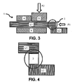
Fig. 3 eine andere Ausführungsform einer schematisierte erfindungsgemäße thermische Abtrennvorrichtung im Betriebsfall, -
Fig. 4 ein schematisiertes Detail einer andere Ausführungsform einer erfindungsgemäßen thermischen Abtrennvorrichtung im Betriebsfall, -
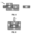
Fig. 5 eine schematisierte erfindungsgemäße thermische Abtrennvorrichtung im ausgelösten Zustand, -
Fig. 6 einen Querschnitt eine schematisiertes Detail einer erfindungsgemäßen thermischen Abtrennvorrichtung im Betriebsfall, und -
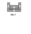
Fig. 7 einen Querschnitt eine schematisiertes Detail einer erfindungsgemäßen thermischen Abtrennvorrichtung im ausgelösten Zustand. - In
Figur 1 ist eine schematisierte thermische Abtrennvorrichtung 1 im Längsschnitt zu sehen. Diese thermische Abtrennvorrichtung 1 weist einen ersten Leiterabschnitt L1 und einen zweiten Leiterabschnitt L2 auf. Der erste Leiterabschnitt L1 und der zweite Leiterabschnitt L2 sind mittels eines thermisch lösbaren Kontaktes 3 verbunden und befinden sich in elektrischem Kontakt zueinander. - Leiterabschnitt L1 befindet sich zumindest abschnittsweise in einem umgebenden Isolierkörper, hier dargestellt durch Abschnitte 4 und 5. Abschnitt 4 als auch Abschnitt 5 sind aus isolierendem Material hergestellt. Dabei kann das Material für Abschnitt 4 sich von dem verwendeten Material für Abschnitt 5 unterscheiden. Abschnitt 4 und Abschnitt5 umgeben in einem gewiesen Abschnitt den Leiterabschnitt L1 und bilden einen umgebenden Isolierkörper.
- Der erste Leiterabschnitt L1 ist mit einer Kraft F1 beaufschlagt ist, so dass, wenn die Kontaktstelle gelöst ist, der ersten Leiterabschnitt L1 in dem umgebenden Isolierkörper 4,5 verbracht wird.
- Die Kontaktstelle 3 kann dabei durch unterschiedliche Mechanismen gelöst werden, z.B. thermisch oder durch mechanische Auftrennung.
- Weiterhin ist z.B. möglich wie in
Figur 1 dargestellt eine Zugkraft F1 vorzusehen, die den ersten Leiterabschnitt L1 in den umgebenden Isolierkörper 4,5 hineinzieht, oder aber wie inFigur 3 dargestellt eine Schubkraft F1 vorzusehen, den ersten Leiterabschnitt L1 in den umgebenden Isolierkörper 4,5 hineinschiebt. Alternativ ist auch eine magnetische Kraft denkbar. - Ohne dies näher zu beschreiben versteht es sich von selbst, dass in gleicher Weise natürlich auch der umgebende Isolierkörper 4,5 relativ zum ersten Leiterabschnitt L1 verbringbar sein kann. Dann würde eine Schubkraft oder Zugkraft den umgebenden Isolierkörper 4,5 über den Leiterabschnitt L1 schieben bzw. ziehen. In diesem Falle wird vorteilhafterweise auch der Leiterabschnitt L2 vom Leiterabschnitt L1 weg bewegt. Dabei kann die Bewegung in Leiterrichtung und/oder normal zur Leiterrichtung verfolgen. Es kommt dabei im Wesentlichen darauf an, den Abstand der Leiterenden zu vergrößern.
- Die Vergrößerung des Abstandes beim Auslösen führt insbesondere bei Wechselstromanwendungen zu einem Abreisen eines eventuell entstehenden Lichtbogens zwischen den nun getrennten Leiterabschnitt L1 und Leiterabschnitt L2. Dies ist möglich, da bei Wechselstromanwendungen innerhalb einer Periode immer ein Nulldurchgang auftritt, so dass der Lichtbogen abreist.
- Dieser Effekt wird durch das Verbringen in den umgebenden Isolierkörper 4,5 unterstützt.
- Für Gleichstromanwendungen kann dies unter Umständen nicht ausreichend sein.
- Um auch hier einen zuverlässigen Abschaltvorgang zu erreichen kann vorgesehen sein, dass der umgebenden Isolierkörper 4,5 einen bewegbaren Abschnitt 5 aufweist.
- Der bewegbare Abschnitt 5 ist dergestalt, dass er, in einer ersten Position wie in
Figur 1 und3 dargestellt, wenn die Kontaktstelle 3 nicht gelöst ist, der Leiterabschnitt L1 bedeckt wird. - In einer zweiten Position - wie in
Figur 5 dargestellt wenn die Kontaktstelle 3 gelöst ist und der Leiterabschnitt L1 hinter den bewegbaren Abschnitt 5 in den Isolierkörper 4 verbracht ist, füllt der bewegbare Abschnitt 5 den vom Leiterabschnitt L1 zuvor eingenommenen Raum. - Somit wird eine effektive Möglichkeit geschaffen, den Lichtbogen durch Ausfüllen des vom Leiterabschnitt L1 zuvor eingenommen Raumes durch den bewegbaren Abschnitt 5 zum Verlöschen zu bringen.
- Weiterhin kann der die thermische Abtrennvorrichtung auch so ausgeführt sein, dass der der bewegbare Abschnitt 5 mit einer Kraft beaufschlagt ist, so dass der bewegbare Abschnitt 5, wenn der Leiterabschnitt L1 in den Isolierkörper 4 verbracht ist, von der Kraft F2 aus der ersten Position in die zweite Position verbringbar ist.
- Weiterhin ist es z.B. möglich, wie in
Figur 1 und3 dargestellt, eine Schubkraft F2 vorzusehen, die den bewegbaren Abschnitt 5 in den Isolierkörper 4 verbringt. - Die Kraft F2 kann beispielsweise mittels einer Feder aufgebracht werden. Alternativ ist auch eine abstoßende magnetische Kraft denkbar.
- Alternativ kann natürlich auch vorgesehen sein, dass der Isolierkörper 4 mit dem Leiterabschnitt L1 relativ zum Abschnitt 5 bewegt wird.
- Weiterhin ist es natürlich auch denkbar, die Verbringung des beweglichen Abschnitts allein durch Schwerkraft herbeizuführen. Es ist jedoch dann auf entsprechende Montage zu achten.
- Alternativ oder zusätzlich kann in allen Ausführungsformen vorgesehen sein, dass der bewegbare Abschnitt 5 zumindest abschnittsweise aus einem ausgasenden Material besteht, um einen eventuell auftretenden Lichtbogen ausblasen zu können.
- Alternativ oder zusätzlich kann in allen Ausführungsformen vorgesehen sein, dass der umgebenden Isolierkörper 4 zumindest abschnittsweise aus einem ausgasenden Material besteht, um einen eventuell auftretenden Lichtbogen ausblasen zu können.
- Bevorzugt ist vorgesehen, dass die lösbare Kontaktstelle 3 eine Lötstelle ist. Alternativ kann vorgesehen sein, dass die Kontaktstelle auch einen thermisch lösbaren Kleber aufweist. Weiterhin stellt die Kontaktstelle 3 eine elektrische Verbindung der Leiterabschnitt L1 und L2 im Betriebszustand zur Verfügung.
- Um eine Auftrennung der lösbaren Kontaktstelle zu bewirken kann vorgesehen sein, dass diese entweder durch Eigenerwärmung oder aber durch Erwärmung seitens anderer Bauteile, z.B. eines Varistors oder dergleichen, selbst erwärmt wird. Alternativ kann natürlich auch vorgesehen sein um eine schnellere Schaltzeit zu gewährleisten eine Erwärmung z.B. mittels eines Heizelementes, vorzusehen.
- Ohne auf einen bestimmten Leiterquerschnitt beschränkt zu sein, erweist sich ein im Wesentlichen reckeckiger Querschnitt als Vorteilhaft, da hierdurch der frei werdende Raum am besten ausgefüllt werden kann. Dies ist für die Löschwirkung von besonderem Vorteil. Es versteht sich von selbst, dass damit auch einhergeht, dass der umgebenden Isolierkörper 4 als auch der bewegbare Abschnitt 5 entsprechend geformt sind.
- In
Fig. 6 ist einen Querschnitt eine schematisiertes Detail einer erfindungsgemäßen thermischen Abtrennvorrichtung im Betriebsfall, und inFig. 7 einen Querschnitt eine schematisiertes Detail einer erfindungsgemäßen thermischen Abtrennvorrichtung im ausgelösten Zustand gezeigt. - Klar zu erkenne ist der bevorzugt rechteckig ausgeführter Querschnitt des Leiterabschnittes L1. Diesem entsprechend ist der Isolierkörper 4 im Bereich des bewegbaren Abschnittes 5 als ein Kanal ausgeführt in dem der bewegbare Abschnitt deckelartig platziert ist.
- Wird der Leiterabschnittes L1 in den Isolierkörper 4 verbracht so kann wie in
Figur 7 dargestellt, der Kanal verschlossen werden. - Wie aus den
Figuren 1 und3 ersichtlich ist, kann die Kontaktstelle 3 geeignet angebracht sein. - In
Figur 1 ist die Kontaktstelle 3 in der Weise angebracht, dass die Leiterabschnitte L1 und L2 stoßartig verbunden sind. - In
Figur 3 ist die Kontaktstelle 3 in der Weise angebracht, dass die Leiterabschnitte L1 und L2 abschnittsweise überlappend verbunden sind. - Es versteht sich jedoch von selbst, dass die Form der Kontaktstelle 3 und ihre Anordnung bezüglich der Leiterabschnitte L1 und L2 auch andere Formen annehmen kann.
- Im Betrieb kann die thermische Abtrennvorrichtung so 1 angeschlossen sein, dass der erste Leiterabschnitt (L1) im Betrieb am Neutralleiter oder an Masse oder am Schutzleiter - also an dem sogenannten kalten Ende - angeschlossen ist.
- Soweit die Erfindung auf eine magnetische Kraft verweist kann diese magnetische Kraft sowohl permanent vorhanden sein, z.B. durch Einbringung magnetischer Bauteile oder aber temporärer Natur sein, z.B. durch Einbringung von elektromagnetischen Bauteilen.
- Weiterhin versteht sich von selbst, dass bei magnetischen Kräften sowohl eine abstoßende als auch anziehende Kräfte vorgesehen sein können.
-
- Thermische Abtrennvorrichtung
- 1
- Erster Leiterabschnitt
- L1
- Zweiter Leiterabschnitt
- L2
- Lösbare Kontaktstelle
- 3
- Umgebender Isolierkörper
- 4
- Beweglicher Abschnitt
- 5
- Kraft
- F1
- Kraft
- F2
Claims (10)
- Thermische Abtrennvorrichtung (1) mit einem ersten Leiterabschnitt (L1) und einem zweiten Leiterabschnitt (L2), wobei der erste Leiterabschnitt (L1) zumindest abschnittsweise in einem umgebenden Isolierkörper (4,5) geführt ist, wobei der erste Leiterabschnitt (L1) und zweite Leiterabschnitt (L2) an einer lösbaren Kontaktstelle (3) miteinander verbunden sind, wobei der erste Leiterabschnitt (L1) mit einer Kraft (F1) beaufschlagt ist, so dass, wenn die Kontaktstelle gelöst ist, der erste Leiterabschnitt in den umgebenden Isolierkörper (4,5) verbracht wird.
- Thermische Abtrennvorrichtung nach Anspruch 1, wobei umgebenden Isolierkörper (4,5) einen bewegbaren Abschnitt (5) aufweist, wobei der bewegbare Abschnitt (5) dergestalt ist, dass er, in einer ersten Position, wenn die Kontaktstelle (3) nicht gelöst ist, der Leiterabschnitt (L1) abschnittsweise überdeckt wird, und in einer zweiten Position, wenn die Kontaktstelle (3) gelöst ist, der Leiterabschnitt (L1) hinter den bewegbaren Abschnitt (5) in den Isolierkörper (4) gezogen ist, der bewegbare Abschnitt (5) den vom Leiterabschnitt (L1) zuvor eingenommenen Raum füllt.
- Thermische Abtrennvorrichtung nach Anspruch 2, wobei der bewegbare Abschnitt (5) mit einer Kraft (F2) beaufschlagt ist, so dass der bewegbare Abschnitt (5) wenn der Leiterabschnitt (L1) in den Isolierkörper (4) gezogen ist, von der Kraft (F2) aus der ersten Position in die zweite Position verbringbar ist.
- Thermische Abtrennvorrichtung nach Anspruch 2 oder 3, wobei der bewegbare Abschnitt (5) zumindest abschnittsweise aus einem ausgasenden Material besteht, um einen eventuell auftretenden Lichtbogen ausblasen zu können.
- Thermische Abtrennvorrichtung nach einem der vorhergehenden Ansprüche, wobei der umgebenden Isolierkörper (4) zumindest abschnittsweise aus einem ausgasenden Material besteht, um einen eventuell auftretenden Lichtbogen ausblasen zu können.
- Thermische Abtrennvorrichtung nach einem der vorhergehenden Ansprüche, wobei die Kontaktstelle eine Lötstelle aufweist.
- Thermische Abtrennvorrichtung nach einem der vorhergehenden Ansprüche, wobei der erste Leiterabschnitt im Wesentlichen einen rechteckigen Durchmesser aufweist.
- Thermische Abtrennvorrichtung nach einem der vorhergehenden Ansprüche, wobei der erste Leiterabschnitt (L1) mit einer Federkraft (F1) beaufschlagt ist, so dass, wenn die Kontaktstelle gelöst ist, der erste Leiterabschnitt in dem umgebenden Isolierkörper (4,5) hineingezogen wird.
- Thermische Abtrennvorrichtung nach einem der vorhergehenden Ansprüche 3 bis 8, wobei der bewegbare Abschnitt (5) mit einer Federkraft (F2) beaufschlagt ist, so dass der bewegbare Abschnitt (5) wenn der Leiterabschnitt (L1) in den Isolierkörper (4) gezogen ist, von der Kraft (F2) aus der ersten Position in die zweite Position verbringbar ist.
- Thermische Abtrennvorrichtung nach einem der vorhergehenden Ansprüche, wobei der erste Leiterabschnitt (L1) im Betrieb am Neutralleiter oder an Masse oder am Schutzleiter angeschlossen ist.
Applications Claiming Priority (2)
| Application Number | Priority Date | Filing Date | Title |
|---|---|---|---|
| DE102010061110A DE102010061110A1 (de) | 2010-12-08 | 2010-12-08 | Thermische Abtrennvorrichtung |
| PCT/EP2011/072114 WO2012076613A1 (de) | 2010-12-08 | 2011-12-07 | Thermische abtrennvorrichtung |
Publications (3)
| Publication Number | Publication Date |
|---|---|
| EP2649631A1 EP2649631A1 (de) | 2013-10-16 |
| EP2649631B1 true EP2649631B1 (de) | 2014-08-27 |
| EP2649631B2 EP2649631B2 (de) | 2018-01-24 |
Family
ID=45470512
Family Applications (1)
| Application Number | Title | Priority Date | Filing Date |
|---|---|---|---|
| EP11807649.6A Active EP2649631B2 (de) | 2010-12-08 | 2011-12-07 | Thermische abtrennvorrichtung |
Country Status (7)
| Country | Link |
|---|---|
| US (1) | US20130337691A1 (de) |
| EP (1) | EP2649631B2 (de) |
| CN (1) | CN103270570B (de) |
| BR (1) | BR112013014020A2 (de) |
| DE (1) | DE102010061110A1 (de) |
| ES (1) | ES2522867T3 (de) |
| WO (1) | WO2012076613A1 (de) |
Families Citing this family (3)
| Publication number | Priority date | Publication date | Assignee | Title |
|---|---|---|---|---|
| DE102014008366B3 (de) * | 2014-06-04 | 2015-10-22 | Dehn + Söhne Gmbh + Co. Kg | Vorrichtung zum thermischen Auslösen oder Abtrennen eines Überspannungsschutzgerätes |
| DE102015014163A1 (de) | 2015-09-08 | 2017-03-09 | DEHN + SÖHNE GmbH + Co. KG. | Vorrichtung zum thermischen Auslösen, Abtrennen und/oder Signalisieren des Zustandes eines Überspannungsschutzgerätes |
| DE102018131975B4 (de) * | 2018-12-12 | 2021-01-14 | Dehn Se + Co Kg | Thermisch auslösbare Anzeige- oder Schalteinrichtung sowie Überspannungsableiteranordnung mit einer thermisch auslösbaren Anzeige- oder Schalteinrichtung |
Family Cites Families (15)
| Publication number | Priority date | Publication date | Assignee | Title |
|---|---|---|---|---|
| DE7501349U (de) † | 1975-08-21 | Dehn + Soehne Gmbh + Co Kg | Überspannungsschutzgerät | |
| DE959660C (de) * | 1953-05-30 | 1957-03-07 | Felten & Guilleaume Carlswerk | Loeschkammer eines Hochspannungs-Leistungsschalters |
| FR2540665B1 (fr) * | 1983-02-04 | 1987-02-27 | Telemecanique Electrique | Dispositif interrupteur muni d'un ecran isolant s'interposant entre les contacts lors de la coupure et de moyen de cisaillement de l'arc entre cet ecran et une paroi isolante |
| FR2573913B1 (fr) * | 1984-11-26 | 1987-01-09 | Telemecanique Electrique | Interrupteur electrique a ecran |
| DD239488A1 (de) † | 1985-07-16 | 1986-09-24 | Elektrogeraete Ingbuero Veb | Thermosicherung |
| DE3723538A1 (de) * | 1987-07-16 | 1989-01-26 | Sachsenwerk Ag | Loeschkammer zur unterbrechung von laststromkreisen |
| US4801772A (en) * | 1988-03-02 | 1989-01-31 | Westinghouse Electric Corp | Current limiting circuit interrupter with insulating wedge |
| DE9217024U1 (de) * | 1992-12-15 | 1993-02-04 | Fritz Driescher KG Spezialfabrik für Elektrizitätswerksbedarf GmbH & Co, 41844 Wegberg | Lasttrennschalter für Mittelspannungsanlagen |
| DE29516057U1 (de) * | 1995-10-10 | 1995-12-07 | Klöckner-Moeller GmbH, 53115 Bonn | Lichtbogenlöscheinrichtung für einen kurzschlußstrombegrenzenden Niederspannungsschalter |
| DE19735521A1 (de) * | 1997-08-16 | 1999-02-18 | Kloeckner Moeller Gmbh | Lichtbogenlöscheinrichtung für einen kurzschlußstrombegrenzenden Niederspannungsschalter |
| US6430019B1 (en) | 1998-06-08 | 2002-08-06 | Ferraz S.A. | Circuit protection device |
| DE10044081A1 (de) * | 2000-09-07 | 2002-04-04 | Bosch Gmbh Robert | Überlastschutz |
| CN1452201A (zh) * | 2003-05-19 | 2003-10-29 | 华南理工大学 | 超温保护装置及其温度敏感材料 |
| DE102007004920B4 (de) † | 2007-01-26 | 2009-08-20 | Siemens Ag | Schutzschalter, insbesondere Leistungsschutzschalter, und thermischen Auslöser für einen Schutzschalter |
| CN201054292Y (zh) * | 2007-03-14 | 2008-04-30 | 何排枝 | 一种避雷器 |
-
2010
- 2010-12-08 DE DE102010061110A patent/DE102010061110A1/de not_active Ceased
-
2011
- 2011-12-07 BR BR112013014020A patent/BR112013014020A2/pt not_active IP Right Cessation
- 2011-12-07 ES ES11807649.6T patent/ES2522867T3/es active Active
- 2011-12-07 EP EP11807649.6A patent/EP2649631B2/de active Active
- 2011-12-07 WO PCT/EP2011/072114 patent/WO2012076613A1/de not_active Ceased
- 2011-12-07 US US13/992,438 patent/US20130337691A1/en not_active Abandoned
- 2011-12-07 CN CN201180058109.5A patent/CN103270570B/zh not_active Expired - Fee Related
Also Published As
| Publication number | Publication date |
|---|---|
| ES2522867T3 (es) | 2014-11-18 |
| BR112013014020A2 (pt) | 2019-09-24 |
| CN103270570B (zh) | 2016-08-10 |
| WO2012076613A1 (de) | 2012-06-14 |
| CN103270570A (zh) | 2013-08-28 |
| DE102010061110A1 (de) | 2012-06-14 |
| EP2649631B2 (de) | 2018-01-24 |
| EP2649631A1 (de) | 2013-10-16 |
| US20130337691A1 (en) | 2013-12-19 |
Similar Documents
| Publication | Publication Date | Title |
|---|---|---|
| DE69016111T2 (de) | Begrenzungsschalter mit einer elektromagnetischen Vorrichtung zur Verzögerung des Zurückfallens des Kontaktes. | |
| DE4104533A1 (de) | Elektrischer schalter | |
| DE102010031907B3 (de) | Unidirektional schaltendes DC-Schütz | |
| DE102006037551B4 (de) | Überspannungsableiter mit mindestens einem Ableitelement, beispielsweise einem Varistor | |
| DE102013019390B4 (de) | Überspannungsschutzeinrichtung, aufweisend mindestens einen Überspannungsableiter und eine, mit dem Überspannungsableiter in Reihe geschaltete, thermisch auslösbare Schalteinrichtung | |
| DE202009013505U1 (de) | Überspannungsschutzelement | |
| EP2649631B2 (de) | Thermische abtrennvorrichtung | |
| DE102016124639B4 (de) | Selbstrücksetzender Strombegrenzer | |
| DE102009036590B3 (de) | Gasisolierte Hochspannungsschaltanlage | |
| WO2016083350A1 (de) | Schaltgerät mit einem antrieb zum betriebsmässigen schalten und mit einem schnellauslöser zum trennen eines strompfads in dem schaltgerät | |
| EP2313905B1 (de) | Schaltgerät | |
| EP2830076B1 (de) | Schaltgerät | |
| DE102019106960B4 (de) | Elektronisches Bauteil | |
| DE102013208656B4 (de) | Schmelzsicherung zur Verwendung in einem Kraftfahrzeug | |
| DE102009035299B4 (de) | Kontaktsystem und Schaltgerät | |
| DE19702818C2 (de) | Schaltanordnung zum wahlweisen Verbinden und Trennen zweier Teilstrecken einer elektrischen Leitung | |
| DE102012207912A1 (de) | Schmelzsicherung, insbesondere Hochvoltschmelzsicherung für ein Kraftfahrzeug | |
| DE102010001648B4 (de) | Trennschalter | |
| DE102018118247B3 (de) | Thermische Sicherung | |
| DE102007034526B3 (de) | Elektrische Schutzeinrichtung | |
| DE102016102604B4 (de) | Elektrische Schaltvorrichtung | |
| EP3549150B1 (de) | Vorrichtung zum trennen eines bordnetzes von einer energiequelle | |
| DE102016110189B4 (de) | Verbindungsvorrichtung mit Steckklemme | |
| AT527218B1 (de) | Stromtrenner | |
| DE102017128054B4 (de) | Expansionskammer eines Fehlerstrom-Schutzschalters und mit dieser ausgestatteter Schutzschalter |
Legal Events
| Date | Code | Title | Description |
|---|---|---|---|
| PUAI | Public reference made under article 153(3) epc to a published international application that has entered the european phase |
Free format text: ORIGINAL CODE: 0009012 |
|
| 17P | Request for examination filed |
Effective date: 20130527 |
|
| AK | Designated contracting states |
Kind code of ref document: A1 Designated state(s): AL AT BE BG CH CY CZ DE DK EE ES FI FR GB GR HR HU IE IS IT LI LT LU LV MC MK MT NL NO PL PT RO RS SE SI SK SM TR |
|
| RIN1 | Information on inventor provided before grant (corrected) |
Inventor name: DEPPING, CHRISTIAN Inventor name: STRIEWE, MARTIN Inventor name: BEHNKE, SVEN |
|
| DAX | Request for extension of the european patent (deleted) | ||
| GRAP | Despatch of communication of intention to grant a patent |
Free format text: ORIGINAL CODE: EPIDOSNIGR1 |
|
| INTG | Intention to grant announced |
Effective date: 20140425 |
|
| GRAS | Grant fee paid |
Free format text: ORIGINAL CODE: EPIDOSNIGR3 |
|
| GRAA | (expected) grant |
Free format text: ORIGINAL CODE: 0009210 |
|
| AK | Designated contracting states |
Kind code of ref document: B1 Designated state(s): AL AT BE BG CH CY CZ DE DK EE ES FI FR GB GR HR HU IE IS IT LI LT LU LV MC MK MT NL NO PL PT RO RS SE SI SK SM TR |
|
| REG | Reference to a national code |
Ref country code: GB Ref legal event code: FG4D Free format text: NOT ENGLISH |
|
| REG | Reference to a national code |
Ref country code: CH Ref legal event code: EP |
|
| REG | Reference to a national code |
Ref country code: AT Ref legal event code: REF Ref document number: 684871 Country of ref document: AT Kind code of ref document: T Effective date: 20140915 |
|
| REG | Reference to a national code |
Ref country code: IE Ref legal event code: FG4D Free format text: LANGUAGE OF EP DOCUMENT: GERMAN |
|
| REG | Reference to a national code |
Ref country code: DE Ref legal event code: R096 Ref document number: 502011004225 Country of ref document: DE Effective date: 20141009 |
|
| REG | Reference to a national code |
Ref country code: ES Ref legal event code: FG2A Ref document number: 2522867 Country of ref document: ES Kind code of ref document: T3 Effective date: 20141118 |
|
| REG | Reference to a national code |
Ref country code: NO Ref legal event code: T2 Effective date: 20140827 |
|
| REG | Reference to a national code |
Ref country code: LT Ref legal event code: MG4D |
|
| REG | Reference to a national code |
Ref country code: NL Ref legal event code: VDEP Effective date: 20140827 |
|
| PG25 | Lapsed in a contracting state [announced via postgrant information from national office to epo] |
Ref country code: FI Free format text: LAPSE BECAUSE OF FAILURE TO SUBMIT A TRANSLATION OF THE DESCRIPTION OR TO PAY THE FEE WITHIN THE PRESCRIBED TIME-LIMIT Effective date: 20140827 Ref country code: SE Free format text: LAPSE BECAUSE OF FAILURE TO SUBMIT A TRANSLATION OF THE DESCRIPTION OR TO PAY THE FEE WITHIN THE PRESCRIBED TIME-LIMIT Effective date: 20140827 Ref country code: BG Free format text: LAPSE BECAUSE OF FAILURE TO SUBMIT A TRANSLATION OF THE DESCRIPTION OR TO PAY THE FEE WITHIN THE PRESCRIBED TIME-LIMIT Effective date: 20141127 Ref country code: LT Free format text: LAPSE BECAUSE OF FAILURE TO SUBMIT A TRANSLATION OF THE DESCRIPTION OR TO PAY THE FEE WITHIN THE PRESCRIBED TIME-LIMIT Effective date: 20140827 Ref country code: PT Free format text: LAPSE BECAUSE OF FAILURE TO SUBMIT A TRANSLATION OF THE DESCRIPTION OR TO PAY THE FEE WITHIN THE PRESCRIBED TIME-LIMIT Effective date: 20141229 Ref country code: GR Free format text: LAPSE BECAUSE OF FAILURE TO SUBMIT A TRANSLATION OF THE DESCRIPTION OR TO PAY THE FEE WITHIN THE PRESCRIBED TIME-LIMIT Effective date: 20141128 |
|
| PG25 | Lapsed in a contracting state [announced via postgrant information from national office to epo] |
Ref country code: IS Free format text: LAPSE BECAUSE OF FAILURE TO SUBMIT A TRANSLATION OF THE DESCRIPTION OR TO PAY THE FEE WITHIN THE PRESCRIBED TIME-LIMIT Effective date: 20141227 Ref country code: HR Free format text: LAPSE BECAUSE OF FAILURE TO SUBMIT A TRANSLATION OF THE DESCRIPTION OR TO PAY THE FEE WITHIN THE PRESCRIBED TIME-LIMIT Effective date: 20140827 Ref country code: LV Free format text: LAPSE BECAUSE OF FAILURE TO SUBMIT A TRANSLATION OF THE DESCRIPTION OR TO PAY THE FEE WITHIN THE PRESCRIBED TIME-LIMIT Effective date: 20140827 Ref country code: CY Free format text: LAPSE BECAUSE OF FAILURE TO SUBMIT A TRANSLATION OF THE DESCRIPTION OR TO PAY THE FEE WITHIN THE PRESCRIBED TIME-LIMIT Effective date: 20140827 Ref country code: RS Free format text: LAPSE BECAUSE OF FAILURE TO SUBMIT A TRANSLATION OF THE DESCRIPTION OR TO PAY THE FEE WITHIN THE PRESCRIBED TIME-LIMIT Effective date: 20140827 |
|
| PG25 | Lapsed in a contracting state [announced via postgrant information from national office to epo] |
Ref country code: NL Free format text: LAPSE BECAUSE OF FAILURE TO SUBMIT A TRANSLATION OF THE DESCRIPTION OR TO PAY THE FEE WITHIN THE PRESCRIBED TIME-LIMIT Effective date: 20140827 |
|
| REG | Reference to a national code |
Ref country code: DE Ref legal event code: R026 Ref document number: 502011004225 Country of ref document: DE |
|
| PG25 | Lapsed in a contracting state [announced via postgrant information from national office to epo] |
Ref country code: SK Free format text: LAPSE BECAUSE OF FAILURE TO SUBMIT A TRANSLATION OF THE DESCRIPTION OR TO PAY THE FEE WITHIN THE PRESCRIBED TIME-LIMIT Effective date: 20140827 Ref country code: CZ Free format text: LAPSE BECAUSE OF FAILURE TO SUBMIT A TRANSLATION OF THE DESCRIPTION OR TO PAY THE FEE WITHIN THE PRESCRIBED TIME-LIMIT Effective date: 20140827 Ref country code: EE Free format text: LAPSE BECAUSE OF FAILURE TO SUBMIT A TRANSLATION OF THE DESCRIPTION OR TO PAY THE FEE WITHIN THE PRESCRIBED TIME-LIMIT Effective date: 20140827 Ref country code: RO Free format text: LAPSE BECAUSE OF FAILURE TO SUBMIT A TRANSLATION OF THE DESCRIPTION OR TO PAY THE FEE WITHIN THE PRESCRIBED TIME-LIMIT Effective date: 20140827 Ref country code: DK Free format text: LAPSE BECAUSE OF FAILURE TO SUBMIT A TRANSLATION OF THE DESCRIPTION OR TO PAY THE FEE WITHIN THE PRESCRIBED TIME-LIMIT Effective date: 20140827 |
|
| PLBP | Opposition withdrawn |
Free format text: ORIGINAL CODE: 0009264 |
|
| PLBI | Opposition filed |
Free format text: ORIGINAL CODE: 0009260 |
|
| PG25 | Lapsed in a contracting state [announced via postgrant information from national office to epo] |
Ref country code: PL Free format text: LAPSE BECAUSE OF FAILURE TO SUBMIT A TRANSLATION OF THE DESCRIPTION OR TO PAY THE FEE WITHIN THE PRESCRIBED TIME-LIMIT Effective date: 20140827 |
|
| 26 | Opposition filed |
Opponent name: DEHN + SOEHNE GMBH + CO.KG Effective date: 20150513 |
|
| PG25 | Lapsed in a contracting state [announced via postgrant information from national office to epo] |
Ref country code: BE Free format text: LAPSE BECAUSE OF NON-PAYMENT OF DUE FEES Effective date: 20141231 |
|
| PLAX | Notice of opposition and request to file observation + time limit sent |
Free format text: ORIGINAL CODE: EPIDOSNOBS2 |
|
| PG25 | Lapsed in a contracting state [announced via postgrant information from national office to epo] |
Ref country code: LU Free format text: LAPSE BECAUSE OF FAILURE TO SUBMIT A TRANSLATION OF THE DESCRIPTION OR TO PAY THE FEE WITHIN THE PRESCRIBED TIME-LIMIT Effective date: 20141207 |
|
| REG | Reference to a national code |
Ref country code: CH Ref legal event code: PL |
|
| REG | Reference to a national code |
Ref country code: IE Ref legal event code: MM4A |
|
| PG25 | Lapsed in a contracting state [announced via postgrant information from national office to epo] |
Ref country code: IE Free format text: LAPSE BECAUSE OF NON-PAYMENT OF DUE FEES Effective date: 20141207 Ref country code: CH Free format text: LAPSE BECAUSE OF NON-PAYMENT OF DUE FEES Effective date: 20141231 Ref country code: LI Free format text: LAPSE BECAUSE OF NON-PAYMENT OF DUE FEES Effective date: 20141231 |
|
| PLBB | Reply of patent proprietor to notice(s) of opposition received |
Free format text: ORIGINAL CODE: EPIDOSNOBS3 |
|
| PG25 | Lapsed in a contracting state [announced via postgrant information from national office to epo] |
Ref country code: SI Free format text: LAPSE BECAUSE OF FAILURE TO SUBMIT A TRANSLATION OF THE DESCRIPTION OR TO PAY THE FEE WITHIN THE PRESCRIBED TIME-LIMIT Effective date: 20140827 |
|
| REG | Reference to a national code |
Ref country code: FR Ref legal event code: PLFP Year of fee payment: 5 |
|
| PGFP | Annual fee paid to national office [announced via postgrant information from national office to epo] |
Ref country code: NO Payment date: 20151222 Year of fee payment: 5 |
|
| PGFP | Annual fee paid to national office [announced via postgrant information from national office to epo] |
Ref country code: ES Payment date: 20151209 Year of fee payment: 5 |
|
| PG25 | Lapsed in a contracting state [announced via postgrant information from national office to epo] |
Ref country code: SM Free format text: LAPSE BECAUSE OF FAILURE TO SUBMIT A TRANSLATION OF THE DESCRIPTION OR TO PAY THE FEE WITHIN THE PRESCRIBED TIME-LIMIT Effective date: 20140827 |
|
| PGFP | Annual fee paid to national office [announced via postgrant information from national office to epo] |
Ref country code: IT Payment date: 20151230 Year of fee payment: 5 |
|
| PG25 | Lapsed in a contracting state [announced via postgrant information from national office to epo] |
Ref country code: MC Free format text: LAPSE BECAUSE OF FAILURE TO SUBMIT A TRANSLATION OF THE DESCRIPTION OR TO PAY THE FEE WITHIN THE PRESCRIBED TIME-LIMIT Effective date: 20140827 |
|
| PG25 | Lapsed in a contracting state [announced via postgrant information from national office to epo] |
Ref country code: TR Free format text: LAPSE BECAUSE OF FAILURE TO SUBMIT A TRANSLATION OF THE DESCRIPTION OR TO PAY THE FEE WITHIN THE PRESCRIBED TIME-LIMIT Effective date: 20140827 Ref country code: MT Free format text: LAPSE BECAUSE OF FAILURE TO SUBMIT A TRANSLATION OF THE DESCRIPTION OR TO PAY THE FEE WITHIN THE PRESCRIBED TIME-LIMIT Effective date: 20140827 Ref country code: HU Free format text: LAPSE BECAUSE OF FAILURE TO SUBMIT A TRANSLATION OF THE DESCRIPTION OR TO PAY THE FEE WITHIN THE PRESCRIBED TIME-LIMIT; INVALID AB INITIO Effective date: 20111207 |
|
| GBPC | Gb: european patent ceased through non-payment of renewal fee |
Effective date: 20151207 |
|
| PG25 | Lapsed in a contracting state [announced via postgrant information from national office to epo] |
Ref country code: GB Free format text: LAPSE BECAUSE OF NON-PAYMENT OF DUE FEES Effective date: 20151207 |
|
| REG | Reference to a national code |
Ref country code: FR Ref legal event code: PLFP Year of fee payment: 6 |
|
| RIC2 | Information provided on ipc code assigned after grant |
Ipc: H02H 9/00 20060101ALI20170410BHEP Ipc: H01C 7/12 20060101ALI20170410BHEP Ipc: H01R 13/516 20060101ALI20170410BHEP Ipc: H01H 33/06 20060101ALI20170410BHEP Ipc: H01H 9/32 20060101AFI20170410BHEP Ipc: H01H 37/76 20060101ALI20170410BHEP |
|
| REG | Reference to a national code |
Ref country code: NO Ref legal event code: MMEP |
|
| PG25 | Lapsed in a contracting state [announced via postgrant information from national office to epo] |
Ref country code: IT Free format text: LAPSE BECAUSE OF NON-PAYMENT OF DUE FEES Effective date: 20161207 Ref country code: NO Free format text: LAPSE BECAUSE OF NON-PAYMENT OF DUE FEES Effective date: 20161231 |
|
| PUAH | Patent maintained in amended form |
Free format text: ORIGINAL CODE: 0009272 |
|
| STAA | Information on the status of an ep patent application or granted ep patent |
Free format text: STATUS: PATENT MAINTAINED AS AMENDED |
|
| REG | Reference to a national code |
Ref country code: FR Ref legal event code: PLFP Year of fee payment: 7 |
|
| 27A | Patent maintained in amended form |
Effective date: 20180124 |
|
| AK | Designated contracting states |
Kind code of ref document: B2 Designated state(s): AL AT BE BG CH CY CZ DE DK EE ES FI FR GB GR HR HU IE IS IT LI LT LU LV MC MK MT NL NO PL PT RO RS SE SI SK SM TR |
|
| REG | Reference to a national code |
Ref country code: DE Ref legal event code: R102 Ref document number: 502011004225 Country of ref document: DE |
|
| REG | Reference to a national code |
Ref country code: AT Ref legal event code: MM01 Ref document number: 684871 Country of ref document: AT Kind code of ref document: T Effective date: 20161207 |
|
| PG25 | Lapsed in a contracting state [announced via postgrant information from national office to epo] |
Ref country code: ES Free format text: LAPSE BECAUSE OF NON-PAYMENT OF DUE FEES Effective date: 20161208 Ref country code: AT Free format text: LAPSE BECAUSE OF NON-PAYMENT OF DUE FEES Effective date: 20161207 |
|
| PG25 | Lapsed in a contracting state [announced via postgrant information from national office to epo] |
Ref country code: MK Free format text: LAPSE BECAUSE OF FAILURE TO SUBMIT A TRANSLATION OF THE DESCRIPTION OR TO PAY THE FEE WITHIN THE PRESCRIBED TIME-LIMIT Effective date: 20140827 |
|
| PG25 | Lapsed in a contracting state [announced via postgrant information from national office to epo] |
Ref country code: ES Free format text: LAPSE BECAUSE OF FAILURE TO SUBMIT A TRANSLATION OF THE DESCRIPTION OR TO PAY THE FEE WITHIN THE PRESCRIBED TIME-LIMIT Effective date: 20180124 |
|
| PG25 | Lapsed in a contracting state [announced via postgrant information from national office to epo] |
Ref country code: AL Free format text: LAPSE BECAUSE OF FAILURE TO SUBMIT A TRANSLATION OF THE DESCRIPTION OR TO PAY THE FEE WITHIN THE PRESCRIBED TIME-LIMIT Effective date: 20140827 |
|
| PGFP | Annual fee paid to national office [announced via postgrant information from national office to epo] |
Ref country code: FR Payment date: 20191223 Year of fee payment: 9 |
|
| REG | Reference to a national code |
Ref country code: ES Ref legal event code: FD2A Effective date: 20200420 |
|
| PG25 | Lapsed in a contracting state [announced via postgrant information from national office to epo] |
Ref country code: ES Free format text: LAPSE BECAUSE OF FAILURE TO SUBMIT A TRANSLATION OF THE DESCRIPTION OR TO PAY THE FEE WITHIN THE PRESCRIBED TIME-LIMIT Effective date: 20161208 |
|
| PG25 | Lapsed in a contracting state [announced via postgrant information from national office to epo] |
Ref country code: FR Free format text: LAPSE BECAUSE OF NON-PAYMENT OF DUE FEES Effective date: 20201231 |
|
| P01 | Opt-out of the competence of the unified patent court (upc) registered |
Effective date: 20230424 |
|
| PGFP | Annual fee paid to national office [announced via postgrant information from national office to epo] |
Ref country code: DE Payment date: 20241230 Year of fee payment: 14 |